EP0260355A1 - Apparatus for detecting inner surface flaw of each pipe constituting pipeline - Google Patents
Apparatus for detecting inner surface flaw of each pipe constituting pipeline Download PDFInfo
- Publication number
- EP0260355A1 EP0260355A1 EP86307148A EP86307148A EP0260355A1 EP 0260355 A1 EP0260355 A1 EP 0260355A1 EP 86307148 A EP86307148 A EP 86307148A EP 86307148 A EP86307148 A EP 86307148A EP 0260355 A1 EP0260355 A1 EP 0260355A1
- Authority
- EP
- European Patent Office
- Prior art keywords
- pipe
- secondary coils
- flaw
- primary coil
- voltage signal
- Prior art date
- Legal status (The legal status is an assumption and is not a legal conclusion. Google has not performed a legal analysis and makes no representation as to the accuracy of the status listed.)
- Granted
Links
Images


Classifications
-
- G—PHYSICS
- G01—MEASURING; TESTING
- G01N—INVESTIGATING OR ANALYSING MATERIALS BY DETERMINING THEIR CHEMICAL OR PHYSICAL PROPERTIES
- G01N27/00—Investigating or analysing materials by the use of electric, electrochemical, or magnetic means
- G01N27/72—Investigating or analysing materials by the use of electric, electrochemical, or magnetic means by investigating magnetic variables
- G01N27/82—Investigating or analysing materials by the use of electric, electrochemical, or magnetic means by investigating magnetic variables for investigating the presence of flaws
- G01N27/90—Investigating or analysing materials by the use of electric, electrochemical, or magnetic means by investigating magnetic variables for investigating the presence of flaws using eddy currents
- G01N27/904—Investigating or analysing materials by the use of electric, electrochemical, or magnetic means by investigating magnetic variables for investigating the presence of flaws using eddy currents with two or more sensors
-
- G—PHYSICS
- G01—MEASURING; TESTING
- G01N—INVESTIGATING OR ANALYSING MATERIALS BY DETERMINING THEIR CHEMICAL OR PHYSICAL PROPERTIES
- G01N27/00—Investigating or analysing materials by the use of electric, electrochemical, or magnetic means
- G01N27/72—Investigating or analysing materials by the use of electric, electrochemical, or magnetic means by investigating magnetic variables
- G01N27/82—Investigating or analysing materials by the use of electric, electrochemical, or magnetic means by investigating magnetic variables for investigating the presence of flaws
- G01N27/90—Investigating or analysing materials by the use of electric, electrochemical, or magnetic means by investigating magnetic variables for investigating the presence of flaws using eddy currents
- G01N27/9046—Investigating or analysing materials by the use of electric, electrochemical, or magnetic means by investigating magnetic variables for investigating the presence of flaws using eddy currents by analysing electrical signals
Definitions
- the present invention relates to an apparatus for detecting an inner surface flaw of each pipe constituting a pipeline.
- An apparatus for detecting a flaw of a pipe with the use of electromagnetic induction is publicly known.
- an apparatus for detecting an outer surface flaw of a pipe with the use of electromagnetic induction is disclosed in Japanese Patent Provisional Publication No.60-11,157 dated January 21, 1985, which comprises: at least one cylindrical primary coil, a high frequency electrical current generator, a plurality of probe coils, i.e., a plurality of cylindrical secondary coils, a multiplexer and a signal processing circuit (hereinafter referred to as the "prior art").
- the at least one primary coil surrounds a pipe to be inspected, and is coaxial with the pipe.
- the pipe is coaxially inserted into the at least one primary coil.
- the inner peripheral surface of the at least one primary coil is spaced apart from the outer peripheral surface of the pipe by a prescribed distance.
- the high frequency electric current generator supplies high frequency electric current to the at least one primary coil to cuase the at least one primary coil to produce an AC magnetic field, and the magnetic flux density of the AC magnetic field varies in response to an outer surface flaw of the pipe.
- the plurality of secondary coils are arranged along the outer surface of the pipe at prescribed intervals in the circumferential direction of the pipe in the close vicinity of the at least one primary coil.
- the axis of each of the plurality of secondary coils is arranged at right angles to the axis of the at least one primary coil.
- Each of the plurality of secondary coils produces an AC voltage proportional to the density of a component parallel to the axial direction of each of the plurality of secondary coils, of the magnetic flux interlinking with each of the plurality of secondary coils, of the AC magnetic field of the at least one primary coil.
- the plurality of secondary coils constitute, together with the at least one primary coil, a detecting probe, and the detecting probe is moved relative to the pipe in the axial direction of the coil.
- the multiplexer repeatedly takes out the AC voltage signals from the plurality of secondary coils sequentially in the order of arrangement of the plurality of secondary coils at a prescribed sampling cycle period T.
- the signal processing circuit comprises a synchronous detector, a delay circuit and an adder.
- the synchronous detector sequentially and synchronously detects the AC voltage signals from the plurality of secondary coils, taken out by the multiplexer, with the high frequency electric current from the high frequency electric current generator as the reference signal, thereby eliminating noise signals from the AC voltage signals from the plurality of secondary coils, and at the same time, converting the AC voltage signals into DC voltage signals.
- Each value of the thus converted DC voltage signals is proportional to the depth of an outer surface flaw of the pipe.
- the delay circuit causes delay of the DC voltage signals from the synchronous detector by a period of time equal to the above-mentioned sampling cycle period T.
- the adder adds the thus delayed DC voltage signal from the delay circuit to a DC voltage signal from the synchronous detector in the next sampling cycle period for each of the plurality of secondary coils, thereby obtaining a DC voltage signal with a minimized detection error in the pipe axial direction of the outer surface flaw of the pipe for each of the plurality of secondary coils.
- the detecting probe comprising the at least one primary coil and the plurality of secondary coils at a high speed in the axial direction of the pipe.
- the above-mentioned prior art which relates to the detection of an outer surface flaw of a pipe, is also applicable to the detection of an inner surface flaw of each pipe constituting a pipeline, by causing the detecting probe comprising the at least one primary coil and the plurality of secondary coils to travel through the pipeline.
- the prior art when detecting any of the outer surface flaw or the inner surface flaw of the pipe, the prior art has the following drawbacks.
- the magnetic flux of the AC magnetic field of the at least one primary coil which is distributed in the axial direction of the pipe in the space near the outer surface or the inner surface of the pipe, comes into an outer or inner surface flaw of the pipe, if any, and as a result, the magnetic flux density in the space near the pipe portion containing the outer or inner surface flaw shows a normal distribution having a peak of the lowest density at the position of the flaw center.
- the magnetic flux has the lowest density at the position of the flaw center, and consists only of a component parallel to the axial direction of the at least one primary coil.
- the magnetic flux has the highest density at the position distant from the flaw center, and consists only of a component parallel to the axial direction of the at least one primary coil.
- the magnetic flux density becomes higher according as the distance from the position of the flaw center increases.
- the magnetic flux is analyzed into a component paralle to the axial direction of the at least one primary coil and a component at right angles to the axial direction of the at least one primary coil, and the latter component increases according as the distance from the position of the flaw center increases to reach the maximum, and then decreases.
- the highest density of the component of the magnetic flux which component is at right angles to the axial direction of the at least one primary coil, exists in the middle between the position of the flaw center and the position distant from the flaw center.
- the difference in the magnetic flux density between the lowest density at the position of the flaw center and the highest density at the position distant from the flaw center corresponds to the depth of the flaw.
- the highest density of the component of the magnetic flux, which component is at right angles to the axial direction of the at least one primary coil, at a position between the position of the flaw center and the position distant from the flaw center also corresponds to the depth of the flaw.
- each of the plurality of secondary coils senses a component at right angles to the axial d irection of the at least one primary coil, i.e., a component parallel to the axial direction of each of the plurality of secondary coils, of the magnetic flux of the AC magnetic field of the at least one primary coil, which magnetic flux interlinks with each of the plurality of secondary coils, and produces an AC voltage proportional to the density of the above-mentioned component. Therefore, it is possible to detect the depth of the outer surface flaw or the inner surface flaw of the pipe, by processing the AC voltage signal produced by each of the plurality of secondary coils.
- the density of the magnetic flux in the axial direction of the pipe, of the AC magnetic field of the at least one primary coil, in the space near the pipe portion containing these flaws shows a distribution in which three normal distributions of the magnetic flux density corresponding respectively to these three flaws partly overlap in the axial direction of the pipe.
- a distribution of the magnetic flux density at a position between the center position of the first flaw and a position opposite to the second flaw relative to the first flaw, and a distribution of the magnetic flux density at a position between the center position of the third flaw and a position opposite to the second flaw relative to the third flaw are not affected by the distribution of the magnetic flux density corresponding to the second flaw. Therefore, the highest densities of the components at right angles to the axial direction of the at least one primary coil of the magnetic flux in these two intermediate positions correspond respectively to the depth of the first flaw and the depth of the third flaw.
- a distribution of the magnetic flux density at a position between the center position of the first flaw and the center position of the second flaw, and a distribution of the magnetic flux density at a position between the center position of the second flaw and the center position of the third flaw, are affected by the distributions of the magnetic flux density corresponding respectively to the first flaw and the third flaw. Therefore, the highest densities of the components at right angles to the axial direction of the at least one primary coil of the magnetic flux in these two intermediate positions do not accurately correspond to the depth of the second flaw. Thus, the depth of the second flaw cannot be accurately detected by the prior art.
- An object of the present invention is therefore to provide an apparatus for detecting, with the use of electromagnetic induction, an inner surface flaw of each pipe constituing a pipeline, which, when detecting an inner surface flaw of each pipe constituting the pipeline, permits accurate detection of the depth of each of three or more inner surface flaws of the pipe even when these inner surface flaws exist on the inner surface of the pipe at close inte rvals.
- an apparatus for detecting an inner surface flaw of each pipe constituting a pipeline which comprises: a pig capable of travelling through a pipeline in the axial direction of each pipe constituting said pipeline; at least one cylindrical primary coil mounted on said pig, said at least one primary coil being coaxial with said pipe, and the outer peripheral surface of said at least one primary coil being spaced apart from the inner peripheral surface of said pipe by a prescribed distance; a high frequency electric current generator mounted on said pig, said high frequency electric current generator supplying high frequency electric current to said at least one primary coil to cause said at least one primary coil to produce an AC magnetic field, and the magnetic flux density of said AC magnetic field varying in response to an inner surface flaw of said pipe; a plurality of cylindrical secondary coils mounted on said pig, each of said plurality of secondary coils producing an AC voltage proportional to the density of a component parallel parallel to the axial direction of each of said plurality of secondary coils, of said magnetic flux interlinking with each of said pluralit
- the magnetic flux densities at the center positions of the first, the second and the third inner surface flaws present the lowest values corresponding to the respective flaws, and each magnetic flux consists only of a component parallel to the axial direction of the at least one primary coil.
- each of the plurality of secondary coils senses a component parallel to the axial direction of each of the plurality of secondary coils, of the magnetic flux of the AC magnetic field of the at least one primary coil, which magnetic flux interlinks with each of the plurality of secondary coils, and produces an AC voltage proportional to the density of the above-mentioned component.
- the present invention was made on the basis of the above-mentioned findings. Now, an embodiment of the apparatus of the present invention for detecting an inner surface flaw of each pipe constituting a pipeline is described with reference to the drawings.
- Fig. 1 is a block diagram illustrating the basic stru cture of an embodiment of the apparatus of the present invention for detecting an inner surface flaw of each pipe constituting a pipeline.
- the apparatus of the present invention basically comprises a pig not shown, a pair of cylindrical primary coils P c , which may be only one primary coil, mounted on the pig, a high frequency electric current generator 2 mounted on the pig, a plurality of cylindrical secondary coils S1, ..., S N mounted on the pig, a multiplexer 3 mounted on the pig, and a signal processing circuit 4 mounted on the pig.
- the pair of primary coils P c and the plurality of secondary coils S1, ... , S N form a detecting probe 1.
- the pig is capable of travelling through a pipeline in the axial direction of each pipe constituting the pipeline.
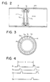
- the pair of primary coils P c forming part of the detecting probe 1 are arranged at a prescribed interval in the axial direction of the pipe 14 as shown in Fig. 2.
- the pair of primary coils P c are coaxial with the pipe 14, and the outer peripheral surfaces of the pair of primary coils P c are spaced apart from the inner peripheral surface of the pipe 14 by a prescribed distance.
- the primary coils P c are arranged in a pair at a prescribed interval in the axial direction of the pipe 14 for the purpose of causing the magnetic flux of the AC magnetic field produced by the pair of primary coils P c to be distributed in the axial direction of the pipe 14 in the space between the outer peripheral surfaces of the pair of primary coils P c and the inner peripheral surface of the pipe 14.
- the high frequency electric current generator 2 supplies high frequency electric current to the pair of primary coils P c to cause the pair of primary coils P c to produce an AC magnetic field.
- the magnetic flux density of the AC magnetic field of the pair of primary coils P c varies in response to an inner surface flaw 14a of the pipe 14.
- the high frequency electric current generator 2 it suffices therefore to cause the high frequency electric current generator 2 to generate a high frequency electric current having a proper frequency in response to the material of the pipe 14 so that the magnetic flux of the AC magnetic field of the pair of primary coils P c penetrates only into the inner surface portion of the pipe 14 .
- the plurality of secondary coils S1, ... , S N are arranged at prescribed intervals in the circumferential direction of the pipe 14 between the outer peripheral surfaces of the pair of primary coils P c and the inner peripheral surface of the pipe 14.
- the axis of each of the plurality of secondary coils S1, ... , S N is parallel to the axis of each of the pair of primary coils P c so as to permit an accurate detection by the plurality of the secondary coils S1, ... , S N , even when three or more inner surface flaws 14a each having a respective depth are present on the inner surface of the pipe 14 at close intervals in the axial direction of the pipe 14, of the depth of each of these inner surface flaws 14a.
- the lowest density of the magnetic flux of the AC magnetic field of the pair of primary coils P c at the center position of each of these inner surface flaws 14a in the space near the portion of the pipe 14 containing these inner surface flaws 14a corresponds only to each of these inner surface flaws 14a, and the magnetic flux consists only of a component parallel to the axial direction of the pair of primary coils P c .
- each of the plurality of secondary coils S1, ..., S N senses a component parallel to the axial direction of each of the plurality of secondary coils S1, ...
- a secondary coil S1 closest to the i nner surface flaw 14a for example, among the plurality of secondary coils S1, ..., S N produces an AC voltage corresponding not only to the depth of the inner surface flaw 14a, but also to the distance between the outer peripheral surfaces of the pair of primary coils P c and the inner peripheral surface of the pipe 14, i.e., between the secondary coil S1 and the inner peripheral surface of the pipe 14.
- the multiplexer 3 repeatedly takes out the AC voltage signals from the plurality of secondary coils S1, ..., S N sequentially in the order of arrangement thereof at a prescribed sampling cycle period ⁇ as shown in Fig. 4. Operations of the multiplexer 3 are controlled by control signals from a multiplexer controller 6.
- the control signal is created, as shown in Fig. 1, in the multiplexer controller 6 on the basis of the high frequency electric current from the high frequency electric current generator 2, which has been divided by a frequency divider 5 into a frequency having a prescribed value.
- the sampling cycle period ⁇ of the AC voltage signals from the plurality of secondary coils S1, ..., S N is set in accordance with conditions for the detection of the inner surface flaw 14a, and usually ranges from 1/104 to 1/10 seconds.
- the signal processing circuit 4 basically comprises, as shown in Fig. 1, a synchronous detector 9, a moving average circuit 11, a flaw detecting circuit 10 and a detection error correcting circuit 13, and has, in addition, am amplifier 7, a noise filter 8 and a moving average circuit controller 12.
- the AC voltage signals from the plurality of secondary coils S1, ..., S N , taken out by the multiplexer 3 are amplified by the amplifier 7, then entered into the synchronous detector 9 after the preliminary elimination of noise signals by the noise filter 8.
- the synchronous detector 9 sequentially and synchronously detects the AC voltage signals from the plurality of secondary coils S1, ..., S N , which have passed through the amplifier 7 and the noise filter 8, with the high frequency electric current from the high frequency electric current generator 2 as the reference signal, thereby eliminating noise signals from the AC voltage signals from the plurality of secondary coils S1, ..., S N , and at the same time, converting the AC voltage signals into DC voltage signals.
- each of the plurality of secondary coils S1, ..., S N produces an AC voltage corresponding to the distance between the outer peripheral surfaces of the pair of primary coils P c and the inner peripheral surface of the pipe 14, i.e., between each of the plurality of secondary coils S1, ..., S N and the inner peripheral surface of the pipe 14.
- the secondary coil S1 closest to the inner surface flaw 14a for example, among the plurality of secondary coils S1, ..., S N produces an AC voltage corresponding not only to the depth of the inner surface flaw 14a, but also to the distance between the secondary coil S1 and the inner peripheral surface of the pipe 14. Therefore, the distance between the secondary coil S1 and the inner peripheral surface of the pipe 14 appears as a bias voltage signal of the DC voltage signal converted by the synchronous detector 9 from the AC voltage signal from the secondary coil S1.
- the above-mentioned bias voltage signal for the secondary coil S1 is equal to the DC voltage signal from the secondary coil S1.
- the depth of the inner surface flaw 14a appears as a differential voltage signal between the DC voltage signal from the synchronous detector 9 corresponding to the AC voltage signal from the secondary coil S1 closest to the inner surface flaw 14a and the bias voltage signal therefor.
- Fig. 5 is a graph illustrating the relationship between the output voltage from the synchronous detector, on the one hand, and the distance (l) between the outer peripheral surfaces of the primary coils and the inner peripheral surface of the pipe, i.e., between the secondary coil and the inner peripheral surface of the pipe 14, on the other hand.
- the ordinate represents the value of the DC voltage signal from the synchronous detector 9, i.e., the value of the bias voltage signal, corresponding to the value of the AC voltage signal from the secondary coil S1, for example, of the plurality of secondary coils S1, .., S N in the case where there is no inner surface flaw 14a on the inner surface of the pipe 14.
- the abscissa represents the distance (l) between that secondary coil S1 and the inner peripheral surface of the pipe 14.
- the output voltage from the synchronous detector 9 represented on the ordinate shows values with the output voltage at a distance (l) of 30 mm as zero V.
- the high frequency electric current supplied to the pair of primary coils P c has a frequency of 100 kHz.
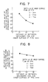
- Fig. 6 is a graph illustrating the relationship between the output voltage from the synchronous detector and the depth (d) of an inner surface flaw of the pipe.
- the ordinate represents the value of the DC voltage signal from the synchronous detector 9, corresponding to the value of the AC voltage signal from the secondary coil S1 closest to the inner surface flaw 14a of the pipe 14, for example, of the plurality of secondary coils S1, ..., S N , in the case where the pair of primary coils P c reach the inner surface flaw 14a.
- the abscissa represents the depth (d) of the inner surface flaw 14a.
- the output voltage from the synchronous detector 9 represented on the ordinate shows values with the output voltage in the case where the pair of primary coils P c do not reach the inner surface flaw 14a as zero V.
- the inner surface flaw 14a was artificially made by a drill.
- the inner surface flaw 14a has a diameter of 30 mm.
- the distance (l) between the secondary coil S1 and the inner peripheral surface of the pipe 14 is 30 mm, and the high frequency electric current supplied to the pair of primary coils P c has a frequency of 100 kHz.
- the output voltage from the synchronous detector 9 decreases according as the depth (d) of the inner surface flaw 14a increases. Therefore, the depth (d) of the inner surface flaw 14a can be detected from the value of the DC voltage signal from the synchronous detector 9.
- the variation in the output voltage from the synchronous detector 9 corresponding to the variation in the depth (d) of the inner surface flaw 14a is maller than the variation in the output voltage from the synchronous detector 9 corresponding to the variation in the distance (l) between the secondary coil S1 and the inner surface of the pipe 14. Therefore, detection of the differential voltage signal between the DC voltage signal and the bias voltage signal by detecting the variation in voltage of the DC voltage signal from the synchronous detector 9 n ot only gives a low detection sensitivity of the depth (d) of the inner surface flaw 14a, but also causes the risk of taking the variation in the distance (l) for the depth (d) of the inner surface flaw 14a.
- the moving average circuit 11 moving-averages the DC voltage signals in a prescribed number from the synchronous detector 9 for each of the plurality of secondary coils S1, ..., S N , thereby sequentially taking out bias voltage signals from the DC voltage signals for each of the plurality of secondary coils S1, ..., S N .
- the number of DC voltage signals from the synchronous detector 9 to be moving-averaged is usually 3 to 10. Operation of the moving average circuit 11 is controlled by control signals from the moving average circuit controller 12.
- the control signal is created, as shown in Fig. 1, in the moving average circuit controller 12 on the basis of the high frequency electric current from the high frequency electric current generator 2, which has been divided by the frequency divider 5 into a frequency having a prescribed value.
- the above-mentioned takeout of the bias voltage signals by the moving average circuit 11 it is possible to obtain the bias voltage signals from which the noise signals caused, for example, by the inclination of each of the plurality of secondary coils S1, ..., S N have been eliminated.
- the flaw detecting circuit 10 sequentially detects a differential voltage signal proportional to the depth (d) of the inner surface flaw 14a of the pipe 14, between the bias voltage signal from the moving average circuit 11 for each of the plurality of secondary coils S1, ..., S N , on the one hand, and a DC voltage signal, which immediately follows the moving-averaging by the moving average circuit 11, from the synchronous detector 9 for each of the plurality of secondary coils S1, ..., S N , on the other hand.
- the value of the bias voltage signal of the DC voltage signal from the synchronous detector 9 varies in proportion to the distance (l). Therefore, the value of the DC voltage signal from the synchronous detector 9 and the value of the dif ferential voltage signal from the flow detection circuit 10 also vary in proportion to the distance (l). Therefore, if the changes in these signal values caused by the change in the distance (l) are not affected by the difference in the depth (d) of the inner surface flaw 14a, it would be possible to correct a detection error of the differential voltage signal resulting from the change in the distance (l) by amplifying the differential voltage signal from the flaw detecting circuit 10 at an amplification degree inversely proportional to the value of the bias voltage signal from the moving average circuit 11.
- Fig. 7 is a graph illustrating the relationship between the relative value of the output voltage from the synchronous detector of the signal processing circuit, on the one hand, and the distance (l) between the secondary coil and the inner surface of the pipe, on the other hand.
- the ordinate represents the relative value of the output voltage from the synchronous detector 9, corresponding to the value of the AC voltage signal from the secondary coil S1 closest to the inner surface flaw 14a of the pipe 14, for example, of the plurality of secondary coils S1, ..., S N , in the case where the pair of primary coils P c reach the inner surface flaw 14a.
- the abscissa represents the distance (l) between that secondary coil S1 and the inner surface of the pipe 14.
- the above-mentioned relative value of the output voltage from the synchronous detector 9 represented on the ordinate was obtained by dividing the value of the DC voltage signal from the synchronous detector 9 by the value of the DC voltage signal from the synchronous detector 9 for a distance (l) of 25 mm between the secondary coil S1 and the inner surface of the pipe 14.
- the inner surface flaw 14a was artificially made by a drill.
- the change in the output voltage from the synchronous detector 9 caused by the change in the distance (l) remains the same irrespective of the depth (d) of the inner surface flaw 14a.
- the detection error correcting circuit 13 amplifies the differential voltage signal from the flaw detecting circuit 10 for each of the plurality of secondary coils S1, ..., S N at an amplification degree inversely proportional to the value of the bias voltage signal from the moving average circuit 11 for each of the plurality of secondary coils S1, ..., S N , thereby correcting a detection error of the differential voltage signal caused by a fluctuation in the distance (l) between each of the plurality of secondary coils S1, ..., S N and the inner surface of the pipe 14.
- Fig. 8 is a graph illustrating the relationship between the relative value of the output voltage from the detection error correcting circuit of the signal processing circuit, on the one hand, and the distance (l) between the secondary coil and the inner surface of the pipe, on the other hand.
- the ordinate represents the relative value of the output voltage from the detection error correcting circuit 13 corresponding to the value of the differential voltage signal of the secondary coil S1 closest to the inner surface flaw 14a of the pipe 14, for example, of the plurality of secondary coils S1, ..., S N , in the case where the pair of primary coils P c reach the inner surface flaw 14a.
- the abscissa represents the distance (l) between that secondary coil S1 and the inner surface of the pipe 14.
- the above-mentioned relative value of the output voltage from the detection error correcting circuit 13 represented on the ordinate was obtained by dividing the value of the DC voltage signal from the detection error correcting circuit 13 by the value of the DC voltage signal from the detection error correcting circuit 13 for a distance (l) of 25 mm between the secondary coil S1 and the inner surface of the pipe.
- the inner surface flaw 14a was artificially made by a drill.
- the relative value of the output voltage from the detection error correcting circuit 13 shows the same value if the distance (l) between the secondary coil S1 and the inner surface of the pipe 14 remains the same, irrespective of the depth (d) of the inner surface flaw 14a, and the ratio of the decrease in the above-mentioned relative value to the distance (l) is very small.
- the DC voltage signal from the detection error correcting circuit 13 shows a value corresponding to the depth (d) of the inner surface flaw 14a even when the distance (l) varies, and in the DC voltage signal from the detection error correcting circuit 13, the detection error of the differential voltage signal from the flaw detecting circuit 10 caused by the change in the distance (l) has been corrected. Therefore, it is possible to accurately detect the depth (d) of the inner surface flaw 14a by using the above-mentioned DC voltage signal from the detection error correcting circuit 13.
- the plurality of secondary coils forming part of the detecting probe are arranged at prescribed intervals in the circumferential direction of a pipe to be inspected between the outer peripheral surface of the at least one primary coil forming part of the detecting probe and the inner peripheral surface of the pipe so that the axis of each of the plurality of secondary coils is parallel to the axis of the at least one primary coil, it is possible to accurately detect the presence and the depth of each of three or more inner surface flaws of each pipe constituting a pipeline even when these inner surface flaws are present at close intervals in the axial direction of the pipe, thus providing industrially useful effects.
Landscapes
- Chemical & Material Sciences (AREA)
- Chemical Kinetics & Catalysis (AREA)
- Electrochemistry (AREA)
- Physics & Mathematics (AREA)
- Health & Medical Sciences (AREA)
- Life Sciences & Earth Sciences (AREA)
- Analytical Chemistry (AREA)
- Biochemistry (AREA)
- General Health & Medical Sciences (AREA)
- General Physics & Mathematics (AREA)
- Immunology (AREA)
- Pathology (AREA)
- Investigating Or Analyzing Materials By The Use Of Magnetic Means (AREA)
Abstract
Description
- The present invention relates to an apparatus for detecting an inner surface flaw of each pipe constituting a pipeline.
- An apparatus for detecting a flaw of a pipe with the use of electromagnetic induction is publicly known. For example, an apparatus for detecting an outer surface flaw of a pipe with the use of electromagnetic induction is disclosed in Japanese Patent Provisional Publication No.60-11,157 dated January 21, 1985, which comprises: at least one cylindrical primary coil, a high frequency electrical current generator, a plurality of probe coils, i.e., a plurality of cylindrical secondary coils, a multiplexer and a signal processing circuit (hereinafter referred to as the "prior art").
- The at least one primary coil surrounds a pipe to be inspected, and is coaxial with the pipe. In other words, the pipe is coaxially inserted into the at least one primary coil. The inner peripheral surface of the at least one primary coil is spaced apart from the outer peripheral surface of the pipe by a prescribed distance.
- The high frequency electric current generator supplies high frequency electric current to the at least one primary coil to cuase the at least one primary coil to produce an AC magnetic field, and the magnetic flux density of the AC magnetic field varies in response to an outer surface flaw of the pipe.
- The plurality of secondary coils are arranged along the outer surface of the pipe at prescribed intervals in the circumferential direction of the pipe in the close vicinity of the at least one primary coil. The axis of each of the plurality of secondary coils is arranged at right angles to the axis of the at least one primary coil. Each of the plurality of secondary coils produces an AC voltage proportional to the density of a component parallel to the axial direction of each of the plurality of secondary coils, of the magnetic flux interlinking with each of the plurality of secondary coils, of the AC magnetic field of the at least one primary coil. The plurality of secondary coils constitute, together with the at least one primary coil, a detecting probe, and the detecting probe is moved relative to the pipe in the axial direction of the coil.
- The multiplexer repeatedly takes out the AC voltage signals from the plurality of secondary coils sequentially in the order of arrangement of the plurality of secondary coils at a prescribed sampling cycle period T.
- The signal processing circuit comprises a synchronous detector, a delay circuit and an adder.
- The synchronous detector sequentially and synchronously detects the AC voltage signals from the plurality of secondary coils, taken out by the multiplexer, with the high frequency electric current from the high frequency electric current generator as the reference signal, thereby eliminating noise signals from the AC voltage signals from the plurality of secondary coils, and at the same time, converting the AC voltage signals into DC voltage signals. Each value of the thus converted DC voltage signals is proportional to the depth of an outer surface flaw of the pipe.
- The delay circuit causes delay of the DC voltage signals from the synchronous detector by a period of time equal to the above-mentioned sampling cycle period T.
- The adder adds the thus delayed DC voltage signal from the delay circuit to a DC voltage signal from the synchronous detector in the next sampling cycle period for each of the plurality of secondary coils, thereby obtaining a DC voltage signal with a minimized detection error in the pipe axial direction of the outer surface flaw of the pipe for each of the plurality of secondary coils.
- In the above-mentioned prior art, it is possible to detect the presence and the d epth of the outer surface flaw of the pipe with a minimized detection error in the axial direction of the pipe, by sequentially detecting a differential voltage signal proportional to the depth of the outer surface flaw of the pipe, between the DC voltage signal from the adder for each of the plurality of secondary coils, on the one hand, and the bias voltage signal thereof resulting from the inclination or other cause of each of the plurality of secondary coils, on the other hand.
- According to the prior art, it is possible to detect an outer surface flaw of the pipe without omission of detection in the pipe axial direction, even when carrying out detecting operation of the outer surface flaw of the pipe while moving, relative to the pipe, the detecting probe comprising the at least one primary coil and the plurality of secondary coils at a high speed in the axial direction of the pipe.
- The above-mentioned prior art, which relates to the detection of an outer surface flaw of a pipe, is also applicable to the detection of an inner surface flaw of each pipe constituting a pipeline, by causing the detecting probe comprising the at least one primary coil and the plurality of secondary coils to travel through the pipeline. However, when detecting any of the outer surface flaw or the inner surface flaw of the pipe, the prior art has the following drawbacks.
- More specifically, the magnetic flux of the AC magnetic field of the at least one primary coil, which is distributed in the axial direction of the pipe in the space near the outer surface or the inner surface of the pipe, comes into an outer or inner surface flaw of the pipe, if any, and as a result, the magnetic flux density in the space near the pipe portion containing the outer or inner surface flaw shows a normal distribution having a peak of the lowest density at the position of the flaw center. This means that, the magnetic flux has the lowest density at the position of the flaw center, and consists only of a component parallel to the axial direction of the at least one primary coil. On the other hand, the magnetic flux has the highest density at the position distant from the flaw center, and consists only of a component parallel to the axial direction of the at least one primary coil. In the middle between the position of the flaw center and the position distant from the flaw center, the magnetic flux density becomes higher according as the distance from the position of the flaw center increases. The magnetic flux is analyzed into a component paralle to the axial direction of the at least one primary coil and a component at right angles to the axial direction of the at least one primary coil, and the latter component increases according as the distance from the position of the flaw center increases to reach the maximum, and then decreases. Therefore, in a space near the pipe portion containing an outer or inner surface flaw, the highest density of the component of the magnetic flux, which component is at right angles to the axial direction of the at least one primary coil, exists in the middle between the position of the flaw center and the position distant from the flaw center.
- The difference in the magnetic flux density between the lowest density at the position of the flaw center and the highest density at the position distant from the flaw center corresponds to the depth of the flaw. The highest density of the component of the magnetic flux, which component is at right angles to the axial direction of the at least one primary coil, at a position between the position of the flaw center and the position distant from the flaw center also corresponds to the depth of the flaw. Since, in the above-mentioned prior art, the plurality of secondary coils are arranged so that the axis of each of the plurality of secondary coils is at right angles to the axis of the at least one primary coil, each of the plurality of secondary coils senses a component at right angles to the axial d irection of the at least one primary coil, i.e., a component parallel to the axial direction of each of the plurality of secondary coils, of the magnetic flux of the AC magnetic field of the at least one primary coil, which magnetic flux interlinks with each of the plurality of secondary coils, and produces an AC voltage proportional to the density of the above-mentioned component. Therefore, it is possible to detect the depth of the outer surface flaw or the inner surface flaw of the pipe, by processing the AC voltage signal produced by each of the plurality of secondary coils.
- However, when a first flaw, a second flaw and a third flaw each having a respective depth are present in this order on the outer or inner surface of the pipe at close intervals in the axial direction of the pipe, the density of the magnetic flux in the axial direction of the pipe, of the AC magnetic field of the at least one primary coil, in the space near the pipe portion containing these flaws, shows a distribution in which three normal distributions of the magnetic flux density corresponding respectively to these three flaws partly overlap in the axial direction of the pipe. In such a distribution of the magnetic flux density, a distribution of the magnetic flux density at a position between the center position of the first flaw and a position opposite to the second flaw relative to the first flaw, and a distribution of the magnetic flux density at a position between the center position of the third flaw and a position opposite to the second flaw relative to the third flaw, are not affected by the distribution of the magnetic flux density corresponding to the second flaw. Therefore, the highest densities of the components at right angles to the axial direction of the at least one primary coil of the magnetic flux in these two intermediate positions correspond respectively to the depth of the first flaw and the depth of the third flaw. On the contrary, a distribution of the magnetic flux density at a position between the center position of the first flaw and the center position of the second flaw, and a distribution of the magnetic flux density at a position between the center position of the second flaw and the center position of the third flaw, are affected by the distributions of the magnetic flux density corresponding respectively to the first flaw and the third flaw. Therefore, the highest densities of the components at right angles to the axial direction of the at least one primary coil of the magnetic flux in these two intermediate positions do not accurately correspond to the depth of the second flaw. Thus, the depth of the second flaw cannot be accurately detected by the prior art.
- Also when four or more flaws are present on the outer or inner surface of the pipe at close intervals in the axial direction of the pipe, the same problem as described above is posed for the flaws other than those at the both ends.
- Under such circumstances, there is a strong demand for the development of an apparatus for detecting, with the use of electromagnetic induction, an inner surface flaw of each pipe constituting a pipeline, which, when detecting an inner surface flaw of each pipe constituting the pipeline, permits accurate detection of the depth of each of three or more inner surface flaws of the pipe even when these inner surface flaws exist on the inner surface of the pipe at close intervals in the axial direction of the pipe, but an apparatus provided with such properties has not as yet been proposed.
- An object of the present invention is therefore to provide an apparatus for detecting, with the use of electromagnetic induction, an inner surface flaw of each pipe constituing a pipeline, which, when detecting an inner surface flaw of each pipe constituting the pipeline, permits accurate detection of the depth of each of three or more inner surface flaws of the pipe even when these inner surface flaws exist on the inner surface of the pipe at close inte rvals.
- In accordance with one of the features of the present invention, there is provided an apparatus for detecting an inner surface flaw of each pipe constituting a pipeline, which comprises:
a pig capable of travelling through a pipeline in the axial direction of each pipe constituting said pipeline;
at least one cylindrical primary coil mounted on said pig, said at least one primary coil being coaxial with said pipe, and the outer peripheral surface of said at least one primary coil being spaced apart from the inner peripheral surface of said pipe by a prescribed distance;
a high frequency electric current generator mounted on said pig, said high frequency electric current generator supplying high frequency electric current to said at least one primary coil to cause said at least one primary coil to produce an AC magnetic field, and the magnetic flux density of said AC magnetic field varying in response to an inner surface flaw of said pipe;
a plurality of cylindrical secondary coils mounted on said pig, each of said plurality of secondary coils producing an AC voltage proportional to the density of a component parallel parallel to the axial direction of each of said plurality of secondary coils, of said magnetic flux interlinking with each of said plurality of secondary coils, of said AC magnetic field of said at least one primary coil;
a multiplexer mounted on said pig, said multiplexer repeatedly taking out said AC voltage signals from said plurality of secondary coils sequentially in the order of arrangement of said plurality of secondary coils; and
a signal processing circuit mounted on said pig, said signal processing circuit processing said AC voltage signals of said plurality of secondary coils from said multiplexer to detect an inner surface flaw of said pipe;
characterized in that:
said plurality of secondary coils (S₁, ..., S N) are arranged at prescribed intervals in the circumferential direction of said pipe (14) between the outer peripheral surface of said at least one primary coil (P c) and the inner peripheral surface of said pipe (14), and the axis of each of said plurality of secondary coils (S₁, ..., S N) is parallel to the axis of said at least one primary coil (P c). - In the accompanying drawings:
- Fig. 1 is a block diagram illustrating the basic structure of an embodiment of the apparatus of the present invention for detecting an inner surface flaw of each pipe constituting a pipeline;
- Fig. 2 is a longitudinal sectional view illustrating the positional relationship between the detecting probe which is one of the components of the apparatus of the present invention shown in Fig. 1 and a pipe to be inspected;
- Fig. 3 is a transverse sectional view illustrating the arrangement of the pair of primary coils and the plurality of secondary coils, which constitute the detecting probe shown in Fig. 2;
- Fig. 4 is a timing chart illustrating the timing for taking out an AC voltage from the plurality of secondary coils by the multiplexer which is one of the components of the apparatus of the present invention shown in Fig. 1;
- Fig. 5 is a graph illustrating the relationship between the output voltage from the synchronous detector of the signal processing circuit, which is one of the components of the apparatus of the present invention shown in Fig. 1, on the one hand, and the distance (ℓ) between the secondary coil and the inner surface of a pipe to be inspected, on the other hand;
- Fig. 6 is a graph illustrating the relationship between the output voltage from the synchronous detector of the signal processing circuit, which is one of the components of the apparatus of the present invention shown in Fig. 1, on the one hand, and the depth (d) of an inner surface flaw of a pipe to be inspected, on the other hand;
- Fig. 7 is a gra ph illustrating the relationship between the relative value of the output voltage from the synchronous detector of the signal processing circuit, which is one of the components of the apparatus of the present invention shown in Fig. 1, on the one hand, and the distance (ℓ) between the secondary coil and the inner surface of a pipe to be inspected, on the other hand; and
- Fig. 8 is a graph illustrating the relationship between the relative value of the output voltage from the detection error correcting circuit of the signal processing circuit, which is one of the components of the apparatus of the present invention shown in Fig. 1, on the one hand, and the distance (ℓ) between the secondary coil and the inner surface of a pipe to be inspected, on the other hand.
- From the the above-mentioned point of view, extensive studies were carried out to develop an apparatus for detecting, with the use of electromagnetic induction, an inner surface flaw of each pipe constituting a pipeline, which, when detecting an inner surface flaw of each pipe constituting the pipeline, permits accurate detection of the depth of each of three or more inner surface flaws of the pipe even when these inner surface flaws exist on the inner surface of the pipe at close intervals in the axial direction of the pipe.
- As a result, the following findings were obtained: When a first flaw, a second flaw and a third flaw each having a respective depth are present in this order on the inner surface of the pipe at close intervals in the axial direction of the pipe, the density of the magnetic flux in the axial direction of the pipe, of the AC magnetic field of the at least one primary coil, in the space near the pipe portion containing these inner surface flaws, shows a distribution in which three normal distributions of the magnetic flux density corresponding respectively to these three inner surface flaws partly overlap in the axial direction of the pipe. Even in such a distribution of the magnetic flux density, the magnetic flux densities at the center positions of the first, the second and the third inner surface flaws correspond respectively to these respective flaws. Therefore, the magnetic flux densities at the center positions of the first, the second and the third inner surface flaws present the lowest values corresponding to the respective flaws, and each magnetic flux consists only of a component parallel to the axial direction of the at least one primary coil. The difference in the magnetic flux density between the lowest density of the magnetic flux at the center position of each of the first, the second and the third inner surface flaws, on the one hand, and the highest density of the magnetic flux at a position distant from each of these flaws, on the other hand, corresponds to the depth of each of the first, the second and the third inner surface flaws. Therefore, by arranging a plurality of secondary coils so that the axis of each of the plurality of secondary coils is parallel to the axis of the at least one primary coil, each of the plurality of secondary coils senses a component parallel to the axial direction of each of the plurality of secondary coils, of the magnetic flux of the AC magnetic field of the at least one primary coil, which magnetic flux interlinks with each of the plurality of secondary coils, and produces an AC voltage proportional to the density of the above-mentioned component. Thus, it is possible to accurately detect the depth of each of the first, the second and the third inner surface flaws of the pipe, by processing the AC voltage signal produced by each of the plurality of secondary coils.
- The present invention was made on the basis of the above-mentioned findings. Now, an embodiment of the apparatus of the present invention for detecting an inner surface flaw of each pipe constituting a pipeline is described with reference to the drawings.
- Fig. 1 is a block diagram illustrating the basic stru cture of an embodiment of the apparatus of the present invention for detecting an inner surface flaw of each pipe constituting a pipeline. As shown in Fig. 1, the apparatus of the present invention basically comprises a pig not shown, a pair of cylindrical primary coils P c, which may be only one primary coil, mounted on the pig, a high frequency electric current generator 2 mounted on the pig, a plurality of cylindrical secondary coils S₁, ..., S N mounted on the pig, a
multiplexer 3 mounted on the pig, and a signal processing circuit 4 mounted on the pig. The pair of primary coils P c and the plurality of secondary coils S₁, ... , S N form a detectingprobe 1. - The pig is capable of travelling through a pipeline in the axial direction of each pipe constituting the pipeline.
- The pair of primary coils P c forming part of the detecting
probe 1 are arranged at a prescribed interval in the axial direction of thepipe 14 as shown in Fig. 2. The pair of primary coils P c are coaxial with thepipe 14, and the outer peripheral surfaces of the pair of primary coils P c are spaced apart from the inner peripheral surface of thepipe 14 by a prescribed distance. The primary coils P c are arranged in a pair at a prescribed interval in the axial direction of thepipe 14 for the purpose of causing the magnetic flux of the AC magnetic field produced by the pair of primary coils P c to be distributed in the axial direction of thepipe 14 in the space between the outer peripheral surfaces of the pair of primary coils P c and the inner peripheral surface of thepipe 14. This allows the magnetic flux to effectively interlink with the plurality of secondary coils S₁, ... , S N, each of which senses a component parallel to the axial direction of each of the plurality of secondary coils S₁, ..., S N, of the magnetic flux of the AC magnetic field of the pair of primary coils P c, and produces an AC voltage proportional to the density of the above-mentioned component. Therefore, by increasing the coil width of the primary coil P c, it suffices to provide only one primary coil P c. - The high frequency electric current generator 2 supplies high frequency electric current to the pair of primary coils P c to cause the pair of primary coils P c to produce an AC magnetic field. The magnetic flux density of the AC magnetic field of the pair of primary coils P cvaries in response to an
inner surface flaw 14a of thepipe 14. With a view to increasing the detection sensitivity of the inner surface flaw of thepipe 14 by the plurality of secondary coils S₁, ... , S N, it is desirable to concentrate the magnetic flux of the AC magnetic field of the pair of primary coils P c into the space between the outer peripheral surfaces of the pair of primary coils P cand the inner peripheral surface of thepipe 14 so that the magnetic flux penetrates only into the inner surface portion of thepipe 14, thereby increasing the density of the magnetic flux in that space. In general, the penetration depth δ of the magnetic flux of the magnetic field of the primary coil into the material is determined from the frequency ƒ of high frequency electric current supplied to the primary coil, electric conductivity σ of the material and the magnetic permeability µ of the material, and is expressed by the formula: δ = 1/√ƒσµ. It suffices therefore to cause the high frequency electric current generator 2 to generate a high frequency electric current having a proper frequency in response to the material of thepipe 14 so that the magnetic flux of the AC magnetic field of the pair of primary coils P c penetrates only into the inner surface portion of thepipe 14 . - As shown in Fig. 3, the plurality of secondary coils S₁, ... , S N are arranged at prescribed intervals in the circumferential direction of the
pipe 14 between the outer peripheral surfaces of the pair of primary coils P c and the inner peripheral surface of thepipe 14. The axis of each of the plurality of secondary coils S₁, ... , S N is parallel to the axis of each of the pair of primary coils P c so as to permit an accurate detection by the plurality of the secondary coils S₁, ... , S N, even when three or moreinner surface flaws 14a each having a respective depth are present on the inner surface of thepipe 14 at close intervals in the axial direction of thepipe 14, of the depth of each of theseinner surface flaws 14a. Even when three or moreinner surface flaws 14a each having a respective depth are present on the inner surface of thepipe 14 at close intervals in the axial direction of thepipe 14, the lowest density of the magnetic flux of the AC magnetic field of the pair of primary coils P c at the center position of each of theseinner surface flaws 14a in the space near the portion of thepipe 14 containing theseinner surface flaws 14a corresponds only to each of theseinner surface flaws 14a, and the magnetic flux consists only of a component parallel to the axial direction of the pair of primary coils P c. The difference in the magnetic flux density between the lowest density of the magnetic flux at the center position of each of theseinner surface flaws 14a, on the one hand, and the highest density of the magnetic flux at a position distant from each of theseinner surface flaws 14a, on the other hand, corresponds to the depth of each of theseinner surface flaws 14a. Therefore, by arranging the plurality of secondary coils S₁, ... , S N as described above, each of the plurality of secondary coils S₁, ..., S N senses a component parallel to the axial direction of each of the plurality of secondary coils S₁, ... , S N, of the magnetic flux of the AC magnetic field of the pair of primary coils P c, which magnetic flux interlinks with each of the plurality of secondary coils S₁, ..., S N, and produces an AC voltage porportional to the density of the above-mentioned component, thus, permitting an accurate detection of the presece and the depth of each of theseinner surface flaws 14a. - When there is no
inner surface flaw 14a on the inner surface of thepipe 14, there is no change in the density of the component parallel to the axial direction of each of the plurality of secondary coils S₁, ..., S N, of the magnetic flux of the AC magnetic field of the pair of primary coils P c, which magnetic flux interlinks with each of the plurality of secondary coils S₁, ..., S N. Therefore, each of the plurality of secondary coils S₁, ..., S Nproduces a constant AC voltage. On the other hand, when a distance between the outer peripheral surfaces of the pair of primary coils P c and the inner peripheral surface of thepipe 14 is changed, the density of the above-mentioned component parallel to the axial direction of each of the plurality of secondary coils S₁, ... S N, of the magnetic flux of the AC magnetic field of the pair of primary coils P c is changed in response to the thus changed distance. Therefore, each of the plurality of secondary coils S₁, ... S N produces an AC voltage corresponding to the thus changed distance. - As is clear from the foregoing, when the detecting
probe 1 travels through thepipe 14 in the arrow direction in Fig. 2 along with the travel of the pig until the pair of primary coils P c reach theinner surface flaw 14a of thepipe 14, a secondary coil S₁ closest to the i nnersurface flaw 14a, for example, among the plurality of secondary coils S₁, ..., S N produces an AC voltage corresponding not only to the depth of theinner surface flaw 14a, but also to the distance between the outer peripheral surfaces of the pair of primary coils P c and the inner peripheral surface of thepipe 14, i.e., between the secondary coil S₁ and the inner peripheral surface of thepipe 14. - The
multiplexer 3 repeatedly takes out the AC voltage signals from the plurality of secondary coils S₁, ..., S N sequentially in the order of arrangement thereof at a prescribed sampling cycle period τ as shown in Fig. 4. Operations of themultiplexer 3 are controlled by control signals from a multiplexer controller 6. The control signal is created, as shown in Fig. 1, in the multiplexer controller 6 on the basis of the high frequency electric current from the high frequency electric current generator 2, which has been divided by afrequency divider 5 into a frequency having a prescribed value. - The sampling cycle period τ of the AC voltage signals from the plurality of secondary coils S₁, ..., S Nis set in accordance with conditions for the detection of the
inner surface flaw 14a, and usually ranges from 1/10⁴ to 1/10 seconds. - The signal processing circuit 4 basically comprises, as shown in Fig. 1, a synchronous detector 9, a moving
average circuit 11, aflaw detecting circuit 10 and a detectionerror correcting circuit 13, and has, in addition,am amplifier 7, a noise filter 8 and a moving average circuit controller 12. - The AC voltage signals from the plurality of secondary coils S₁, ..., S N, taken out by the
multiplexer 3 are amplified by theamplifier 7, then entered into the synchronous detector 9 after the preliminary elimination of noise signals by the noise filter 8. - The synchronous detector 9 sequentially and synchronously detects the AC voltage signals from the plurality of secondary coils S₁, ..., S N, which have passed through the
amplifier 7 and the noise filter 8, with the high frequency electric current from the high frequency electric current generator 2 as the reference signal, thereby eliminating noise signals from the AC voltage signals from the plurality of secondary coils S₁, ..., S N, and at the same time, converting the AC voltage signals into DC voltage signals. - As described above, when the pair of primary coils P c do not reach the
inner surface flaw 14a of thepipe 14, each of the plurality of secondary coils S₁, ..., S N produces an AC voltage corresponding to the distance between the outer peripheral surfaces of the pair of primary coils P c and the inner peripheral surface of thepipe 14, i.e., between each of the plurality of secondary coils S₁, ..., S N and the inner peripheral surface of thepipe 14. When the pair of primary coils P c reach theinner surface flaw 14a along with the travel of the detectingprobe 1, the secondary coil S₁ closest to theinner surface flaw 14a, for example, among the plurality of secondary coils S₁, ..., S N produces an AC voltage corresponding not only to the depth of theinner surface flaw 14a, but also to the distance between the secondary coil S₁ and the inner peripheral surface of thepipe 14. Therefore, the distance between the secondary coil S₁ and the inner peripheral surface of thepipe 14 appears as a bias voltage signal of the DC voltage signal converted by the synchronous detector 9 from the AC voltage signal from the secondary coil S₁. More specifically, when the pair of primary coils P c do not reach theinner surface flaw 14a, the above-mentioned bias voltage signal for the secondary coil S₁ is equal to the DC voltage signal from the secondary coil S₁. The depth of theinner surface flaw 14a appears as a differential voltage signal between the DC voltage signal from the synchronous detector 9 corresponding to the AC voltage signal from the secondary coil S₁ closest to theinner surface flaw 14a and the bias voltage signal therefor. - Fig. 5 is a graph illustrating the relationship between the output voltage from the synchronous detector, on the one hand, and the distance (ℓ) between the outer peripheral surfaces of the primary coils and the inner peripheral surface of the pipe, i.e., between the secondary coil and the inner peripheral surface of the
pipe 14, on the other hand. In Fig. 5, the ordinate represents the value of the DC voltage signal from the synchronous detector 9, i.e., the value of the bias voltage signal, corresponding to the value of the AC voltage signal from the secondary coil S₁, for example, of the plurality of secondary coils S₁, .., S N in the case where there is noinner surface flaw 14a on the inner surface of thepipe 14. The abscissa represents the distance (ℓ) between that secondary coil S₁ and the inner peripheral surface of thepipe 14. The output voltage from the synchronous detector 9 represented on the ordinate shows values with the output voltage at a distance (ℓ) of 30 mm as zero V. The high frequency electric current supplied to the pair of primary coils P chas a frequency of 100 kHz. - As is clear from Fig. 5, the output voltage from the synchronous detector 9 in the case where there is no
inner surface flaw 14a decreases almost linearly according as the distance (ℓ) between the secondary coil S₁ and the inner peripheral surface of thepipe 14 increases. This demonstrates that the value of the bias voltage signal from the synchronous detector 9 varies in proportion to the distance (ℓ). - Fig. 6 is a graph illustrating the relationship between the output voltage from the synchronous detector and the depth (d) of an inner surface flaw of the pipe. In Fig. 6, the ordinate represents the value of the DC voltage signal from the synchronous detector 9, corresponding to the value of the AC voltage signal from the secondary coil S₁ closest to the
inner surface flaw 14a of thepipe 14, for example, of the plurality of secondary coils S₁, ..., S N, in the case where the pair of primary coils P c reach theinner surface flaw 14a. The abscissa represents the depth (d) of theinner surface flaw 14a. The output voltage from the synchronous detector 9 represented on the ordinate shows values with the output voltage in the case where the pair of primary coils P c do not reach theinner surface flaw 14a as zero V. Theinner surface flaw 14a was artificially made by a drill. Theinner surface flaw 14a has a diameter of 30 mm. The distance (ℓ) between the secondary coil S₁ and the inner peripheral surface of thepipe 14 is 30 mm, and the high frequency electric current supplied to the pair of primary coils P c has a frequency of 100 kHz. - As is clear from Fig. 6, the output voltage from the synchronous detector 9 decreases according as the depth (d) of the
inner surface flaw 14a increases. Therefore, the depth (d) of theinner surface flaw 14a can be detected from the value of the DC voltage signal from the synchronous detector 9. - However, as is clear from Figs, 5 and 6, the variation in the output voltage from the synchronous detector 9 corresponding to the variation in the depth (d) of the
inner surface flaw 14a is maller than the variation in the output voltage from the synchronous detector 9 corresponding to the variation in the distance (ℓ) between the secondary coil S₁ and the inner surface of thepipe 14. Therefore, detection of the differential voltage signal between the DC voltage signal and the bias voltage signal by detecting the variation in voltage of the DC voltage signal from the synchronous detector 9 n ot only gives a low detection sensitivity of the depth (d) of theinner surface flaw 14a, but also causes the risk of taking the variation in the distance (ℓ) for the depth (d) of theinner surface flaw 14a. Therefore, it is necessary to obtain the differential voltage signal proportional to the depth (d) of theinner surface flaw 14a, between the DC voltage signal which is entered from the synchronous detector 9 directly into theflaw detecting circuit 10, on the one hand, and the DC voltage signal which has been entered from the synchronous detector 9 into the movingaverage circuit 11 and has been moving-averaged there and is then entered from the movingaverage circuit 11 into theflaw detecting circuit 10, on the other hand. - More specifically, the moving
average circuit 11 moving-averages the DC voltage signals in a prescribed number from the synchronous detector 9 for each of the plurality of secondary coils S₁, ..., S N, thereby sequentially taking out bias voltage signals from the DC voltage signals for each of the plurality of secondary coils S₁, ..., S N. - The number of DC voltage signals from the synchronous detector 9 to be moving-averaged is usually 3 to 10. Operation of the moving
average circuit 11 is controlled by control signals from the moving average circuit controller 12. The control signal is created, as shown in Fig. 1, in the moving average circuit controller 12 on the basis of the high frequency electric current from the high frequency electric current generator 2, which has been divided by thefrequency divider 5 into a frequency having a prescribed value. According to the above-mentioned takeout of the bias voltage signals by the movingaverage circuit 11, it is possible to obtain the bias voltage signals from which the noise signals caused, for example, by the inclination of each of the plurality of secondary coils S₁, ..., S N have been eliminated. - The
flaw detecting circuit 10 sequentially detects a differential voltage signal proportional to the depth (d) of theinner surface flaw 14a of thepipe 14, between the bias voltage signal from the movingaverage circuit 11 for each of the plurality of secondary coils S₁, ..., S N, on the one hand, and a DC voltage signal, which immediately follows the moving-averaging by the movingaverage circuit 11, from the synchronous detector 9 for each of the plurality of secondary coils S₁, ..., S N, on the other hand. By detecting the above-mentioned differential voltage signal, it is possible to detect the depth (d) of theinner surface flaw 14a at a high detection sensitivity and without confusing with the change in the distance (ℓ) between each of the plurality of secondary coils S₁, ..., S N and the inner peripheral surface of thepipe 14. - However, along with the change in the distance (ℓ) between each of the plurality of secondary coils S₁, ..., S N and the inner surface of the
pipe 14, there occurs a change in the portion of the AC voltage from each of the secondary coils S₁, ..., S N, corresponding to the depth (d) of theinner surface flaw 14a. More particularly, not only the bias voltage signal of the DC voltage signal from the synchronous detector 9, but also the differential voltage signal between the DC voltage signal and the bias voltage signal are affected by the change in the distance (ℓ). As a result, the above-mentioned differential voltage signal detected by theflaw detecting circuit 10 does not accurately correspond to the depth (d) of theinner surface flaw 14a, but originally contains an error signal. As described above with reference to Fig. 5, the value of the bias voltage signal of the DC voltage signal from the synchronous detector 9 varies in proportion to the distance (ℓ). Therefore, the value of the DC voltage signal from the synchronous detector 9 and the value of the dif ferential voltage signal from theflow detection circuit 10 also vary in proportion to the distance (ℓ). Therefore, if the changes in these signal values caused by the change in the distance (ℓ) are not affected by the difference in the depth (d) of theinner surface flaw 14a, it would be possible to correct a detection error of the differential voltage signal resulting from the change in the distance (ℓ) by amplifying the differential voltage signal from theflaw detecting circuit 10 at an amplification degree inversely proportional to the value of the bias voltage signal from the movingaverage circuit 11. - Fig. 7 is a graph illustrating the relationship between the relative value of the output voltage from the synchronous detector of the signal processing circuit, on the one hand, and the distance (ℓ) between the secondary coil and the inner surface of the pipe, on the other hand. In Fig. 7, the ordinate represents the relative value of the output voltage from the synchronous detector 9, corresponding to the value of the AC voltage signal from the secondary coil S₁ closest to the
inner surface flaw 14a of thepipe 14, for example, of the plurality of secondary coils S₁, ..., S N, in the case where the pair of primary coils P c reach theinner surface flaw 14a. The abscissa represents the distance (ℓ) between that secondary coil S₁ and the inner surface of thepipe 14. The above-mentioned relative value of the output voltage from the synchronous detector 9 represented on the ordinate was obtained by dividing the value of the DC voltage signal from the synchronous detector 9 by the value of the DC voltage signal from the synchronous detector 9 for a distance (ℓ) of 25 mm between the secondary coil S₁ and the inner surface of thepipe 14. Theinner surface flaw 14a was artificially made by a drill. - As is clear from Fig. 7, according as the distance (ℓ) between the secondary coil S₁ and the inner surface of the
pipe 14 varies from 25 mm to 30 mm, and from 30 mm to 35 mm, the relative value of the output voltage from the synchronous detector 9 decreases fro all the depths (d) of theinner surface flaw 14a of 3 mm, 5 mm and 7 mm, whereas the extent of this decrease is the same for the same distance (ℓ), and the ratio of the decrease in the above-mentioned relative value to the distance (ℓ) remains the same without difference dependent on the depth (d) of theinner surface flaw 14a. More particularly, while the value of the DC voltage signal itself from the synchronous detector 9 contains a difference dependent on the depth (d) of theinner surface flaw 14a, the change in the output voltage from the synchronous detector 9 caused by the change in the distance (ℓ) remains the same irrespective of the depth (d) of theinner surface flaw 14a. As described above, therefore, it is possible to correct a detection error of the differential voltage signal resulting from the change in the distance (ℓ) by amplifying the differential voltage signal from theflaw detecting circuit 10 at an amplification degree inversely proportional to the value of the bias voltage signal from the movingaverage circuit 10. - More specifically, the detection
error correcting circuit 13 amplifies the differential voltage signal from theflaw detecting circuit 10 for each of the plurality of secondary coils S₁, ..., S N at an amplification degree inversely proportional to the value of the bias voltage signal from the movingaverage circuit 11 for each of the plurality of secondary coils S₁, ..., S N, thereby correcting a detection error of the differential voltage signal caused by a fluctuation in the distance (ℓ) between each of the plurality of secondary coils S₁, ..., S N and the inner surface of thepipe 14. - Fig. 8 is a graph illustrating the relationship between the relative value of the output voltage from the detection error correcting circuit of the signal processing circuit, on the one hand, and the distance (ℓ) between the secondary coil and the inner surface of the pipe, on the other hand. In Fig. 8, the ordinate represents the relative value of the output voltage from the detection
error correcting circuit 13 corresponding to the value of the differential voltage signal of the secondary coil S₁ closest to theinner surface flaw 14a of thepipe 14, for example, of the plurality of secondary coils S₁, ..., S N, in the case where the pair of primary coils P c reach theinner surface flaw 14a. The abscissa represents the distance (ℓ) between that secondary coil S₁ and the inner surface of thepipe 14. The above-mentioned relative value of the output voltage from the detectionerror correcting circuit 13 represented on the ordinate was obtained by dividing the value of the DC voltage signal from the detectionerror correcting circuit 13 by the value of the DC voltage signal from the detectionerror correcting circuit 13 for a distance (ℓ) of 25 mm between the secondary coil S₁ and the inner surface of the pipe. Theinner surface flaw 14a was artificially made by a drill. - As is clear from Fig. 8, the relative value of the output voltage from the detection
error correcting circuit 13 shows the same value if the distance (ℓ) between the secondary coil S₁ and the inner surface of thepipe 14 remains the same, irrespective of the depth (d) of theinner surface flaw 14a, and the ratio of the decrease in the above-mentioned relative value to the distance (ℓ) is very small. More specifically, the DC voltage signal from the detectionerror correcting circuit 13 shows a value corresponding to the depth (d) of theinner surface flaw 14a even when the distance (ℓ) varies, and in the DC voltage signal from the detectionerror correcting circuit 13, the detection error of the differential voltage signal from theflaw detecting circuit 10 caused by the change in the distance (ℓ) has been corrected. Therefore, it is possible to accurately detect the depth (d) of theinner surface flaw 14a by using the above-mentioned DC voltage signal from the detectionerror correcting circuit 13. - According to the apparatus of the present invention, as described above in detail, in which the plurality of secondary coils forming part of the detecting probe are arranged at prescribed intervals in the circumferential direction of a pipe to be inspected between the outer peripheral surface of the at least one primary coil forming part of the detecting probe and the inner peripheral surface of the pipe so that the axis of each of the plurality of secondary coils is parallel to the axis of the at least one primary coil, it is possible to accurately detect the presence and the depth of each of three or more inner surface flaws of each pipe constituting a pipeline even when these inner surface flaws are present at close intervals in the axial direction of the pipe, thus providing industrially useful effects.
Claims (3)
a pig capable of travelling through a pipeline in the axial direction of each pipe constituting said pipeline;
at least one cylindrical primary coil mounted on said pig, said at least one primary coil being coaxial with said pipe, and the outer peripheral surface of said at least one primary coil being spaced apart from the inner peripheral surface of said pipe by a prescribed distance;
a high frequency electric current generator mounted on said pig, said high frequency electric current generator supplying high frequency electric current to said at least one primary coil to cause said at least one primary coil to produce and AC magnetic field, and the magnetic flux density of said AC magnetic field varying in response to an inner surface flaw of sai d pipe;
a plurality of cylindrical secondary coils mounted on said pig, each of said plurality of secondary coils producing an AC voltage proportional to the density of a component parallel to the axial direction of each of said plurality of secondary coils, of said magnetic flux interlinking with each of said plurality of secondary coils, of said AC magnetic field of said at least one primary coil;
a multiplexer mounted on said pig, said multiplexer repeatedly taking out said AC voltage signals from said plurality of secondary coils sequentially in the order of arrangement of said plurality of secondary coils; and
a signal processing circuit mounted on said pig, said signal processing circuit processing said AC voltage signals of said plurality of secondary coils from said multiplexer to detect an inner surface flaw of said pipe;
characterized in that:
said plurality of secondary coils (S₁, ..., S N) are arranged at prescribed intervals in the circumferential direction of said pipe (14) between the outer peripheral surface of said at least one primary coil (P c) and the inner peripheral surface of said pipe (14), and the axis of each of said plurality of secondary coils (S₁, ..., S N) is parallel to the axis of said at least one primary coil (P c).
said signal processing circuit (4) comprises a synchronous detector (9), a moving average circuit (11) and a flaw detecting circuit (10);
said synchronous detector (9) sequentially and synchronously detects said AC voltage signals from said plurality of secondary coils (S₁, ..., S N), taken out by said multiplexer (3), with said high frequency electric current from said high frequency electric current generator (2) as the reference signal, thereby eliminating noise signals from said AC voltage signals from said plurality of secondary coils (S₁, ..., S N) and at the same time, convering said AC voltage signals into DC voltage signals;
said moving average circuit (11) moving-averages said DC voltage signals in a prescribed number from said synchronous detector (9) for each of said plurality of secondary coils (S₁, ..., S N), thereby sequentially taking out bias voltage signals from said DC voltage signals for each of said plurality of secondary coils (S₁, ..., S N); and
said flaw detecting circuit (10) sequentially detects a differential voltage signal proportional to the depth of said inner surface flaw 14a of said pipe (14), between said bias voltage signal from said moving average circuit (11) for each of said plurality of secondary coils (S₁, ..., S N), on the one hand, and a DC voltage signal, which immediately follows said moving-averaging by said moving average circuit (11), from said synchronous detector (9) for each of said plurality of secondary coils (S₁, ..., S N), on the other hand.
said signal processing circuit (4) further includes a detection error correcting circuit (13), said detection error correcting circuit (13) amplifies said differential voltage signal from said flaw detecting circuit (10) for each of said plurality of secondary coils (S₁, ..., S N) at an amplification degree inversely proportional to the value of said bias voltage signal from said moving average circuit (11) for each of said plurality of secondary coils (S₁, ..., S N), thereby correcting a detection error of said differential voltage signal caused by a fluctuation in distance between each of said plurality of secondary coils (S₁, ..., S N) and the inner peripheral surface of said pipe (14).
Priority Applications (1)
| Application Number | Priority Date | Filing Date | Title |
|---|---|---|---|
| DE8686307148T DE3671969D1 (en) | 1986-09-17 | 1986-09-17 | DEVICE FOR DETECTING INTERNAL SURFACE ERRORS OF EVERY TUBE THAT MAKES A PIPELINE. |
Applications Claiming Priority (1)
| Application Number | Priority Date | Filing Date | Title |
|---|---|---|---|
| JP60063368A JPH073408B2 (en) | 1985-03-29 | 1985-03-29 | Pipeline pitting detector |
Publications (2)
| Publication Number | Publication Date |
|---|---|
| EP0260355A1 true EP0260355A1 (en) | 1988-03-23 |
| EP0260355B1 EP0260355B1 (en) | 1990-06-13 |
Family
ID=13227263
Family Applications (1)
| Application Number | Title | Priority Date | Filing Date |
|---|---|---|---|
| EP86307148A Expired EP0260355B1 (en) | 1985-03-29 | 1986-09-17 | Apparatus for detecting inner surface flaw of each pipe constituting pipeline |
Country Status (3)
| Country | Link |
|---|---|
| US (1) | US4742298A (en) |
| EP (1) | EP0260355B1 (en) |
| JP (1) | JPH073408B2 (en) |
Cited By (9)
| Publication number | Priority date | Publication date | Assignee | Title |
|---|---|---|---|---|
| GB2225115A (en) * | 1988-11-07 | 1990-05-23 | Atomic Energy Authority Uk | Eddy current defect testing system |
| GB2225117A (en) * | 1988-11-16 | 1990-05-23 | Nnc Ltd | Eddy current non-destructive examination |
| FR2693797A1 (en) * | 1992-07-20 | 1994-01-21 | Geophysique Cie Gle | Control system for pipes, especially bare or coated steel pipes. |
| DE29606519U1 (en) * | 1996-04-10 | 1997-08-14 | Debnar Beinssen Angelika Dipl | Material test probe |
| US5864229A (en) * | 1991-06-11 | 1999-01-26 | Millstrong Limited | Eddy current probe system and method for determining the midpoint and depth of a discontinuity |
| FR2819313A1 (en) * | 2000-12-26 | 2002-07-12 | Zao Neftegazcomplektservice | Defect inspection magnetometer, used in e.g. high pressure gas pipelines, comprises magnetic sensor rings, multiplexer, amplifier and signal processing instrumentation |
| WO2004088301A1 (en) * | 2003-04-01 | 2004-10-14 | Varco I/P, Inc. | A method and apparatus for inspecting a tubular |
| CN102621503A (en) * | 2012-03-15 | 2012-08-01 | 西南石油大学 | Air coupled magnetic field testing device of magnetic flux leakage detector for oil and gas pipelines and testing method |
| US8336406B2 (en) * | 2007-03-12 | 2012-12-25 | Baker Hughes Incorporated | Protection elements for pipeline investigation devices |
Families Citing this family (37)
| Publication number | Priority date | Publication date | Assignee | Title |
|---|---|---|---|---|
| JPS63138259A (en) * | 1986-12-01 | 1988-06-10 | Nkk Corp | Magnetism probing method |
| US4785243A (en) * | 1987-01-29 | 1988-11-15 | Ltv Steel Company | Electronically scanned eddy current flaw inspection |
| US4808927A (en) * | 1987-02-19 | 1989-02-28 | Atomic Energy Of Canada Limited | Circumferentially compensating eddy current probe with alternately polarized receiver coil |
| JP2651177B2 (en) * | 1988-02-12 | 1997-09-10 | 大阪瓦斯株式会社 | Metal tube defect inspection method |
| US5130653A (en) * | 1990-08-17 | 1992-07-14 | Coors Brewing Company | Apparatus for detecting surface flaws in cylindrical articles |
| US5237270A (en) * | 1990-10-11 | 1993-08-17 | Atomic Energy Of Canada Limited | Ferromagnetic eddy current probe having eccentric magnetization for detecting anomalies in a tube |
| US5256966A (en) * | 1991-04-19 | 1993-10-26 | Combustion Engineering, Inc. | Method for detecting flaws in a steam generator tube using a flexible eddy current probe having coil bank switching |
| GB2255184B (en) * | 1991-04-22 | 1995-08-16 | Tokyo Gas Co Ltd | Flaw detector for metal material |
| US5570017A (en) * | 1992-09-30 | 1996-10-29 | Canada Conveyor Belt Co., Inc. | Apparatus and method of damage detection for magnetically permeable members using an alternating magnetic field and hall effect sensors |
| US5426362A (en) * | 1992-09-30 | 1995-06-20 | Ninnis; Ronald M. | Damage detection apparatus and method for a conveyor belt having magnetically permeable members |
| US5565633A (en) * | 1993-07-30 | 1996-10-15 | Wernicke; Timothy K. | Spiral tractor apparatus and method |
| US5454276A (en) * | 1993-07-30 | 1995-10-03 | Wernicke; Timothy K. | Multi-directional magnetic flux pipe inspection apparatus and method |
| US5479100A (en) * | 1994-05-10 | 1995-12-26 | Gas Research Institute | Method for detecting anomalies in pipes |
| US5537035A (en) * | 1994-05-10 | 1996-07-16 | Gas Research Institute | Apparatus and method for detecting anomalies in ferrous pipe structures |
| AU5312296A (en) | 1995-03-14 | 1996-10-02 | Profile Technologies, Inc. | Reflectometry methods for insulated pipes |
| EP0885396A4 (en) | 1996-02-27 | 2007-09-26 | Profile Technologies Inc | Pipe testing apparatus and method |
| DE29608664U1 (en) * | 1996-05-13 | 1997-09-18 | Debnar Beinssen Angelika Dipl | Device for testing the material of a metallic wall |
| US7196529B2 (en) * | 2003-05-06 | 2007-03-27 | Profile Technologies, Inc. | Systems and methods for testing conductive members employing electromagnetic back scattering |
| EP1629228B1 (en) * | 2003-05-06 | 2017-08-16 | WaveTrue, Inc. | Method for non-destructively testing conductive members employing electromagnetic back scattering |
| US7642790B2 (en) * | 2003-05-06 | 2010-01-05 | Profile Technologies, Inc. | Systems and methods for testing conductive members employing electromagnetic back scattering |
| US7104147B2 (en) * | 2004-01-30 | 2006-09-12 | Shell Oil Company | System and method for measuring electric current in a pipeline |
| JP2005315864A (en) * | 2004-03-30 | 2005-11-10 | Osaka Gas Co Ltd | Impedance measuring method and diagnostic method for piping corroded condition |
| US7821247B2 (en) * | 2005-01-27 | 2010-10-26 | Shell Oil Company | System and method for measuring electric current in a pipeline |
| US7317308B2 (en) * | 2005-01-27 | 2008-01-08 | Shell Oil Company | System and method for measuring electric current in a pipeline |
| JP4701389B2 (en) * | 2005-05-23 | 2011-06-15 | 学校法人金沢工業大学 | Defect inspection system for electrode surface of fuel cell |
| US7295004B2 (en) * | 2006-03-03 | 2007-11-13 | Gary Kroner | Eddy current probe and method of manufacture thereof |
| US20070230536A1 (en) * | 2006-03-28 | 2007-10-04 | Mtu Aero Engines Gmbh | Method and apparatus for detection of flaws in a metal component |
| DE102007054969B4 (en) * | 2007-11-17 | 2015-07-16 | Eisenmann Ag | Device and method for contactless determination of a state variable, in particular the position, at least one pig |
| US20090160437A1 (en) * | 2007-12-21 | 2009-06-25 | Carbon Steel Inspection, Inc. | Eddy Current Probe And Method Of Manufacture Thereof |
| US9964520B2 (en) * | 2014-01-20 | 2018-05-08 | Sintokogio, Ltd. | Surface property inspection device and method |
| US9562955B2 (en) * | 2014-01-20 | 2017-02-07 | Qualcomm Incorporated | Methods and apparatus for magnetic field strength measurement |
| JP6472334B2 (en) * | 2015-06-03 | 2019-02-20 | 日立Geニュークリア・エナジー株式会社 | Eddy current inspection device |
| CN107941904B (en) * | 2017-12-21 | 2018-12-18 | 西安交通大学 | Inspection probe and detection method in aerial metal path defective tube |
| CN108362770B (en) * | 2018-01-17 | 2019-01-18 | 西安交通大学 | Inspection probe and detection method in carbon fibre reinforced composite fitting structure defect |
| DE102018209318A1 (en) * | 2018-06-12 | 2019-12-12 | Bayerische Motoren Werke Aktiengesellschaft | Sensor device and method for testing and / or characterizing a measurement object |
| CN109521084A (en) * | 2018-11-22 | 2019-03-26 | 大唐东北电力试验研究院有限公司 | A kind of buried pipeline weak magnetic method of determination and evaluation |
| CN113983921A (en) * | 2021-11-02 | 2022-01-28 | 西南石油大学 | Buried depth detection method and device for buried pipeline |
Citations (5)
| Publication number | Priority date | Publication date | Assignee | Title |
|---|---|---|---|---|
| FR2018637A1 (en) * | 1968-09-23 | 1970-06-26 | American Mach & Foundry | Control apparatus for bore pipes and similar bodies |
| US4105972A (en) * | 1976-04-09 | 1978-08-08 | British Gas Corporation | Pipeline inspection vehicle for detecting defects in pipeline walls |
| EP0019091A1 (en) * | 1979-05-09 | 1980-11-26 | Schlumberger Limited | Method and apparatus for pipe inspection |
| GB1586581A (en) * | 1977-01-26 | 1981-03-18 | British Gas Corp | Pipeline inspection equipment |
| EP0065325A2 (en) * | 1981-05-11 | 1982-11-24 | Shell Internationale Researchmaatschappij B.V. | Method and apparatus for detecting flaws in tubular metallic members |
Family Cites Families (11)
| Publication number | Priority date | Publication date | Assignee | Title |
|---|---|---|---|---|
| DE4337555A1 (en) * | 1993-11-04 | 1995-05-11 | Schloemann Siemag Ag | Method for rolling finished profiles from a preliminary profile by means of a roll stand arrangement working in reversing operation |
| US2124579A (en) * | 1937-01-30 | 1938-07-26 | Steel And Tubes Inc | Method of and apparatus for testing metallic articles |
| US2555853A (en) * | 1945-04-16 | 1951-06-05 | Emmett M Irwin | Magnetic testing apparatus and method |
| US3597678A (en) * | 1968-12-24 | 1971-08-03 | Williams Brothers Co | Apparatus for sensing thickness variations, discontinuities, and the like in elongated steel structures by measuring variations in magnetic properties utilizing a flux gate |
| US3593122A (en) * | 1969-03-27 | 1971-07-13 | Amf Inc | Method and apparatus for identifying hardspots in magnetizable material |
| JPS55101044A (en) * | 1979-01-29 | 1980-08-01 | Denshi Jiki Kogyo Kk | Flaw detector |
| JPS57113362A (en) * | 1981-01-06 | 1982-07-14 | Nippon Kokan Kk <Nkk> | Probe coil type eddy current flaw detecting method |
| JPS57182643A (en) * | 1981-05-08 | 1982-11-10 | Tokushu Toryo Kk | Tester for eddy current |
| JPS6011157A (en) * | 1983-07-01 | 1985-01-21 | Nippon Kokan Kk <Nkk> | Eddy current flaw detection of probe coil type |
| US4649343A (en) * | 1983-12-27 | 1987-03-10 | The Babcock & Wilcox Company | Electromagnetic flux leakage inspection system for ferromagnetic tubes |
| DE10047158C1 (en) * | 2000-09-22 | 2002-05-16 | Alcan Gmbh | Process for the manufacture of circuit boards for motor vehicle license plates and film for use in such a process |
-
1985
- 1985-03-29 JP JP60063368A patent/JPH073408B2/en not_active Expired - Fee Related
-
1986
- 1986-09-16 US US06/907,840 patent/US4742298A/en not_active Expired - Fee Related
- 1986-09-17 EP EP86307148A patent/EP0260355B1/en not_active Expired
Patent Citations (5)
| Publication number | Priority date | Publication date | Assignee | Title |
|---|---|---|---|---|
| FR2018637A1 (en) * | 1968-09-23 | 1970-06-26 | American Mach & Foundry | Control apparatus for bore pipes and similar bodies |
| US4105972A (en) * | 1976-04-09 | 1978-08-08 | British Gas Corporation | Pipeline inspection vehicle for detecting defects in pipeline walls |
| GB1586581A (en) * | 1977-01-26 | 1981-03-18 | British Gas Corp | Pipeline inspection equipment |
| EP0019091A1 (en) * | 1979-05-09 | 1980-11-26 | Schlumberger Limited | Method and apparatus for pipe inspection |
| EP0065325A2 (en) * | 1981-05-11 | 1982-11-24 | Shell Internationale Researchmaatschappij B.V. | Method and apparatus for detecting flaws in tubular metallic members |
Non-Patent Citations (1)
| Title |
|---|
| PATENT ABSTRACTS OF JAPAN, vol. 9, no. 127 (P-360)[1850], 31st May 1985; & JP - A - 60 11157 (NIPPON KOKAN K.K.) 21-01-1985 * |
Cited By (18)
| Publication number | Priority date | Publication date | Assignee | Title |
|---|---|---|---|---|
| GB2225115A (en) * | 1988-11-07 | 1990-05-23 | Atomic Energy Authority Uk | Eddy current defect testing system |
| US5483160A (en) * | 1988-11-07 | 1996-01-09 | United Kingdom Atomic Energy Authority | Eddy current testing system with scanning probe head having parallel and normal sensing coils |
| GB2225115B (en) * | 1988-11-07 | 1993-07-21 | Atomic Energy Authority Uk | Eddy current testing system |
| US5019777A (en) * | 1988-11-07 | 1991-05-28 | United Kingdom Atomic Energy Authority | Eddy current testing program with scanning probe head having parallel and normal sensing coils |
| GB2225117B (en) * | 1988-11-16 | 1993-02-10 | Nnc Ltd | Eddy current non-destructive examination |
| EP0370691A1 (en) * | 1988-11-16 | 1990-05-30 | Nnc Limited | Non-destructive examination using eddy current |
| GB2225117A (en) * | 1988-11-16 | 1990-05-23 | Nnc Ltd | Eddy current non-destructive examination |
| US5864229A (en) * | 1991-06-11 | 1999-01-26 | Millstrong Limited | Eddy current probe system and method for determining the midpoint and depth of a discontinuity |
| FR2693797A1 (en) * | 1992-07-20 | 1994-01-21 | Geophysique Cie Gle | Control system for pipes, especially bare or coated steel pipes. |
| EP0580485A1 (en) * | 1992-07-20 | 1994-01-26 | Compagnie Generale De Geophysique | System for the inspection of canalisation, especially of steel, jacketed or not |
| DE29606519U1 (en) * | 1996-04-10 | 1997-08-14 | Debnar Beinssen Angelika Dipl | Material test probe |
| FR2819313A1 (en) * | 2000-12-26 | 2002-07-12 | Zao Neftegazcomplektservice | Defect inspection magnetometer, used in e.g. high pressure gas pipelines, comprises magnetic sensor rings, multiplexer, amplifier and signal processing instrumentation |
| GB2376077A (en) * | 2000-12-26 | 2002-12-04 | Ngks Internat Corp | Pipeline inspection apparatus |
| GB2376077B (en) * | 2000-12-26 | 2003-07-09 | Ngks Internat Corp | Pipeline inspection apparatus |
| US6931748B2 (en) * | 2002-04-05 | 2005-08-23 | Varco I/P, Inc. | Riser and tubular inspection systems |
| WO2004088301A1 (en) * | 2003-04-01 | 2004-10-14 | Varco I/P, Inc. | A method and apparatus for inspecting a tubular |
| US8336406B2 (en) * | 2007-03-12 | 2012-12-25 | Baker Hughes Incorporated | Protection elements for pipeline investigation devices |
| CN102621503A (en) * | 2012-03-15 | 2012-08-01 | 西南石油大学 | Air coupled magnetic field testing device of magnetic flux leakage detector for oil and gas pipelines and testing method |
Also Published As
| Publication number | Publication date |
|---|---|
| JPH073408B2 (en) | 1995-01-18 |
| US4742298A (en) | 1988-05-03 |
| EP0260355B1 (en) | 1990-06-13 |
| JPS61223549A (en) | 1986-10-04 |
Similar Documents
| Publication | Publication Date | Title |
|---|---|---|
| EP0260355A1 (en) | Apparatus for detecting inner surface flaw of each pipe constituting pipeline | |
| EP0122899B1 (en) | Apparatus and method employing extraneous field compensation for locating current-carrying objects | |
| US3875502A (en) | Coil arrangement and circuit for eddy current testing | |
| JP4563633B2 (en) | Inductive measurement method for objects | |
| EP1660842B1 (en) | Position sensors | |
| EP0556114B1 (en) | Logging method and apparatus for investigating geometrical characteristics of a borehole | |
| EP0332048A3 (en) | Multiple coil eddy current probe and method of flaw detection | |
| US5260662A (en) | Conductivity method and apparatus for measuring strata resistivity adjacent a borehole | |
| US5461312A (en) | Remote field eddy current sensor for detecting flaws in metal material | |
| US4771238A (en) | Device for measuring, without contact, the thickness of metallic materials at temperatures above the Curie temperature | |
| GB1585580A (en) | Metal detectors | |
| AU2002216205B2 (en) | Measurement of stress in a ferromagnetic material | |
| US4567435A (en) | Method and apparatus for continuously measuring distance utilizing eddy current and having temperature difference influence elimination | |
| EP0065325A3 (en) | Method and apparatus for detecting flaws in tubular metallic members | |
| EP0886756B1 (en) | Method and device of inductive measurement of physical parameters of an object of metallic material together with use of the method and the device | |
| JPH0989843A (en) | Method and apparatus for eddy current flaw detection | |
| US5548212A (en) | Thickness and hardness measurement apparatus utilizing a rotating induction vector | |
| JP2002257789A (en) | Leakage flux detecting device | |
| US4750134A (en) | Device for the non-destructive testing of ferromagnetic bodies and a process for producing values for adjusting the device into an initial state for testing determined by the respective test samples | |
| CA1265595A (en) | Apparatus for detecting surface flaw of pipeline by electromagnetic induction | |
| JP3035724B2 (en) | Metal detection method | |
| JPS6340850A (en) | Eddy current inspecting device | |
| JPS62294987A (en) | Method and apparatus for measuring magnetic property | |
| SU947407A1 (en) | Apparatus for investigating casing strings in well | |
| JPS6345555A (en) | Inspection method for pitting corrosion of steel tube |
Legal Events
| Date | Code | Title | Description |
|---|---|---|---|
| PUAI | Public reference made under article 153(3) epc to a published international application that has entered the european phase |
Free format text: ORIGINAL CODE: 0009012 |
|
| 17P | Request for examination filed |
Effective date: 19870730 |
|
| AK | Designated contracting states |
Kind code of ref document: A1 Designated state(s): DE FR GB NL |
|
| 17Q | First examination report despatched |
Effective date: 19880623 |
|
| GRAA | (expected) grant |
Free format text: ORIGINAL CODE: 0009210 |
|
| AK | Designated contracting states |
Kind code of ref document: B1 Designated state(s): DE FR GB NL |
|
| ET | Fr: translation filed | ||
| REF | Corresponds to: |
Ref document number: 3671969 Country of ref document: DE Date of ref document: 19900719 |
|
| PLBE | No opposition filed within time limit |
Free format text: ORIGINAL CODE: 0009261 |
|
| STAA | Information on the status of an ep patent application or granted ep patent |
Free format text: STATUS: NO OPPOSITION FILED WITHIN TIME LIMIT |
|
| 26N | No opposition filed | ||
| PGFP | Annual fee paid to national office [announced via postgrant information from national office to epo] |
Ref country code: GB Payment date: 19920907 Year of fee payment: 7 |
|
| PGFP | Annual fee paid to national office [announced via postgrant information from national office to epo] |
Ref country code: FR Payment date: 19920909 Year of fee payment: 7 |
|
| PGFP | Annual fee paid to national office [announced via postgrant information from national office to epo] |
Ref country code: NL Payment date: 19920930 Year of fee payment: 7 |
|
| PGFP | Annual fee paid to national office [announced via postgrant information from national office to epo] |
Ref country code: DE Payment date: 19921005 Year of fee payment: 7 |
|
| PG25 | Lapsed in a contracting state [announced via postgrant information from national office to epo] |
Ref country code: GB Effective date: 19930917 |
|
| PG25 | Lapsed in a contracting state [announced via postgrant information from national office to epo] |
Ref country code: NL Effective date: 19940401 |
|
| GBPC | Gb: european patent ceased through non-payment of renewal fee |
Effective date: 19930917 |
|
| NLV4 | Nl: lapsed or anulled due to non-payment of the annual fee | ||
| PG25 | Lapsed in a contracting state [announced via postgrant information from national office to epo] |
Ref country code: FR Free format text: LAPSE BECAUSE OF NON-PAYMENT OF DUE FEES Effective date: 19940531 |
|
| PG25 | Lapsed in a contracting state [announced via postgrant information from national office to epo] |
Ref country code: DE Effective date: 19940601 |
|
| REG | Reference to a national code |
Ref country code: FR Ref legal event code: ST |