EP0259109A2 - Permeable membranes having high flux-density and low fouling propensity and processes including their use - Google Patents
Permeable membranes having high flux-density and low fouling propensity and processes including their use Download PDFInfo
- Publication number
- EP0259109A2 EP0259109A2 EP87307630A EP87307630A EP0259109A2 EP 0259109 A2 EP0259109 A2 EP 0259109A2 EP 87307630 A EP87307630 A EP 87307630A EP 87307630 A EP87307630 A EP 87307630A EP 0259109 A2 EP0259109 A2 EP 0259109A2
- Authority
- EP
- European Patent Office
- Prior art keywords
- grooves
- permeable membrane
- membrane
- sheets
- sheet
- Prior art date
- Legal status (The legal status is an assumption and is not a legal conclusion. Google has not performed a legal analysis and makes no representation as to the accuracy of the status listed.)
- Withdrawn
Links
- 239000012528 membrane Substances 0.000 title claims abstract description 367
- 238000000034 method Methods 0.000 title claims description 53
- 230000008569 process Effects 0.000 title claims description 40
- 230000004907 flux Effects 0.000 title claims description 37
- 239000012466 permeate Substances 0.000 claims abstract description 84
- 238000000926 separation method Methods 0.000 claims abstract description 59
- 230000004888 barrier function Effects 0.000 claims description 39
- 239000007788 liquid Substances 0.000 claims description 31
- 238000001223 reverse osmosis Methods 0.000 claims description 31
- 239000007789 gas Substances 0.000 claims description 26
- 239000000203 mixture Substances 0.000 claims description 23
- 239000012530 fluid Substances 0.000 claims description 21
- 239000000047 product Substances 0.000 claims description 21
- 239000002904 solvent Substances 0.000 claims description 19
- 239000004744 fabric Substances 0.000 claims description 14
- 238000000108 ultra-filtration Methods 0.000 claims description 13
- -1 poly(methylmethacrylate) Polymers 0.000 claims description 11
- 239000011248 coating agent Substances 0.000 claims description 8
- 238000000576 coating method Methods 0.000 claims description 8
- 239000000376 reactant Substances 0.000 claims description 8
- 239000004695 Polyether sulfone Substances 0.000 claims description 6
- 230000003204 osmotic effect Effects 0.000 claims description 6
- 229920006393 polyether sulfone Polymers 0.000 claims description 6
- 239000003054 catalyst Substances 0.000 claims description 4
- 239000002245 particle Substances 0.000 claims description 4
- 239000004926 polymethyl methacrylate Substances 0.000 claims description 4
- 229920003229 poly(methyl methacrylate) Polymers 0.000 claims description 3
- 229920002492 poly(sulfone) Polymers 0.000 claims description 3
- 239000004801 Chlorinated PVC Substances 0.000 claims description 2
- 239000002033 PVDF binder Substances 0.000 claims description 2
- 239000004793 Polystyrene Substances 0.000 claims description 2
- 229920002396 Polyurea Polymers 0.000 claims description 2
- 239000004760 aramid Substances 0.000 claims description 2
- 229920003235 aromatic polyamide Polymers 0.000 claims description 2
- IISBACLAFKSPIT-UHFFFAOYSA-N bisphenol A Chemical compound C=1C=C(O)C=CC=1C(C)(C)C1=CC=C(O)C=C1 IISBACLAFKSPIT-UHFFFAOYSA-N 0.000 claims description 2
- 229920002678 cellulose Polymers 0.000 claims description 2
- 229920000457 chlorinated polyvinyl chloride Polymers 0.000 claims description 2
- 238000010924 continuous production Methods 0.000 claims description 2
- 229920000889 poly(m-phenylene isophthalamide) Polymers 0.000 claims description 2
- 229920002037 poly(vinyl butyral) polymer Polymers 0.000 claims description 2
- 239000004417 polycarbonate Substances 0.000 claims description 2
- 229920000515 polycarbonate Polymers 0.000 claims description 2
- 229920002223 polystyrene Polymers 0.000 claims description 2
- 229920002981 polyvinylidene fluoride Polymers 0.000 claims description 2
- 238000009740 moulding (composite fabrication) Methods 0.000 abstract description 13
- 210000004379 membrane Anatomy 0.000 description 307
- 108091006146 Channels Proteins 0.000 description 109
- 239000012510 hollow fiber Substances 0.000 description 46
- 239000010410 layer Substances 0.000 description 42
- XLYOFNOQVPJJNP-UHFFFAOYSA-N water Substances O XLYOFNOQVPJJNP-UHFFFAOYSA-N 0.000 description 22
- 238000005266 casting Methods 0.000 description 17
- 239000000243 solution Substances 0.000 description 17
- 238000013461 design Methods 0.000 description 16
- 238000011045 prefiltration Methods 0.000 description 16
- 230000008901 benefit Effects 0.000 description 14
- 238000006243 chemical reaction Methods 0.000 description 13
- 230000010287 polarization Effects 0.000 description 13
- 239000000306 component Substances 0.000 description 11
- 239000000463 material Substances 0.000 description 10
- 238000012856 packing Methods 0.000 description 10
- VLKZOEOYAKHREP-UHFFFAOYSA-N n-Hexane Chemical compound CCCCCC VLKZOEOYAKHREP-UHFFFAOYSA-N 0.000 description 9
- 229920000642 polymer Polymers 0.000 description 9
- 125000006850 spacer group Chemical group 0.000 description 9
- FAPWRFPIFSIZLT-UHFFFAOYSA-M Sodium chloride Chemical compound [Na+].[Cl-] FAPWRFPIFSIZLT-UHFFFAOYSA-M 0.000 description 8
- 238000010612 desalination reaction Methods 0.000 description 8
- 238000004519 manufacturing process Methods 0.000 description 8
- 238000011160 research Methods 0.000 description 8
- 239000010409 thin film Substances 0.000 description 8
- 230000015572 biosynthetic process Effects 0.000 description 7
- 238000005516 engineering process Methods 0.000 description 7
- 235000013305 food Nutrition 0.000 description 7
- 238000005755 formation reaction Methods 0.000 description 7
- 230000035699 permeability Effects 0.000 description 7
- IJGRMHOSHXDMSA-UHFFFAOYSA-N Atomic nitrogen Chemical compound N#N IJGRMHOSHXDMSA-UHFFFAOYSA-N 0.000 description 6
- 239000002131 composite material Substances 0.000 description 6
- 239000000835 fiber Substances 0.000 description 6
- 239000010408 film Substances 0.000 description 6
- 229920003266 Leaf® Polymers 0.000 description 5
- FXHOOIRPVKKKFG-UHFFFAOYSA-N N,N-Dimethylacetamide Chemical compound CN(C)C(C)=O FXHOOIRPVKKKFG-UHFFFAOYSA-N 0.000 description 5
- 239000007864 aqueous solution Substances 0.000 description 5
- QVGXLLKOCUKJST-UHFFFAOYSA-N atomic oxygen Chemical compound [O] QVGXLLKOCUKJST-UHFFFAOYSA-N 0.000 description 5
- 208000037516 chromosome inversion disease Diseases 0.000 description 5
- LYCAIKOWRPUZTN-UHFFFAOYSA-N ethylene glycol Substances OCCO LYCAIKOWRPUZTN-UHFFFAOYSA-N 0.000 description 5
- 239000012982 microporous membrane Substances 0.000 description 5
- 239000001301 oxygen Substances 0.000 description 5
- 229910052760 oxygen Inorganic materials 0.000 description 5
- 238000012545 processing Methods 0.000 description 5
- 239000000853 adhesive Substances 0.000 description 4
- 230000001070 adhesive effect Effects 0.000 description 4
- 239000000178 monomer Substances 0.000 description 4
- 239000011148 porous material Substances 0.000 description 4
- 230000002829 reductive effect Effects 0.000 description 4
- 239000011780 sodium chloride Substances 0.000 description 4
- 241000894007 species Species 0.000 description 4
- 238000012360 testing method Methods 0.000 description 4
- 230000001112 coagulating effect Effects 0.000 description 3
- 238000011161 development Methods 0.000 description 3
- 239000012527 feed solution Substances 0.000 description 3
- 238000001914 filtration Methods 0.000 description 3
- 230000006870 function Effects 0.000 description 3
- 229910052751 metal Inorganic materials 0.000 description 3
- 239000002184 metal Substances 0.000 description 3
- 229910052757 nitrogen Inorganic materials 0.000 description 3
- 229920003023 plastic Polymers 0.000 description 3
- 239000004033 plastic Substances 0.000 description 3
- 238000002360 preparation method Methods 0.000 description 3
- 238000000746 purification Methods 0.000 description 3
- 238000011084 recovery Methods 0.000 description 3
- 239000007787 solid Substances 0.000 description 3
- 239000000758 substrate Substances 0.000 description 3
- 238000011144 upstream manufacturing Methods 0.000 description 3
- 239000002699 waste material Substances 0.000 description 3
- KBPLFHHGFOOTCA-UHFFFAOYSA-N 1-Octanol Chemical compound CCCCCCCCO KBPLFHHGFOOTCA-UHFFFAOYSA-N 0.000 description 2
- XNWFRZJHXBZDAG-UHFFFAOYSA-N 2-METHOXYETHANOL Chemical compound COCCO XNWFRZJHXBZDAG-UHFFFAOYSA-N 0.000 description 2
- QGZKDVFQNNGYKY-UHFFFAOYSA-N Ammonia Chemical compound N QGZKDVFQNNGYKY-UHFFFAOYSA-N 0.000 description 2
- CURLTUGMZLYLDI-UHFFFAOYSA-N Carbon dioxide Chemical compound O=C=O CURLTUGMZLYLDI-UHFFFAOYSA-N 0.000 description 2
- 229920003171 Poly (ethylene oxide) Polymers 0.000 description 2
- 239000004743 Polypropylene Substances 0.000 description 2
- 229920004695 VICTREX™ PEEK Polymers 0.000 description 2
- 239000008280 blood Substances 0.000 description 2
- 210000004369 blood Anatomy 0.000 description 2
- WERYXYBDKMZEQL-UHFFFAOYSA-N butane-1,4-diol Chemical compound OCCCCO WERYXYBDKMZEQL-UHFFFAOYSA-N 0.000 description 2
- 230000008859 change Effects 0.000 description 2
- 229910052729 chemical element Inorganic materials 0.000 description 2
- 238000003889 chemical engineering Methods 0.000 description 2
- 238000004140 cleaning Methods 0.000 description 2
- 230000002860 competitive effect Effects 0.000 description 2
- 238000010276 construction Methods 0.000 description 2
- 238000001723 curing Methods 0.000 description 2
- 230000001419 dependent effect Effects 0.000 description 2
- 125000000118 dimethyl group Chemical group [H]C([H])([H])* 0.000 description 2
- 238000001035 drying Methods 0.000 description 2
- 238000000605 extraction Methods 0.000 description 2
- 229930195733 hydrocarbon Natural products 0.000 description 2
- 150000002430 hydrocarbons Chemical class 0.000 description 2
- WGCNASOHLSPBMP-UHFFFAOYSA-N hydroxyacetaldehyde Natural products OCC=O WGCNASOHLSPBMP-UHFFFAOYSA-N 0.000 description 2
- 230000000670 limiting effect Effects 0.000 description 2
- 238000001471 micro-filtration Methods 0.000 description 2
- 230000003071 parasitic effect Effects 0.000 description 2
- 229920005597 polymer membrane Polymers 0.000 description 2
- 238000006116 polymerization reaction Methods 0.000 description 2
- 229920001155 polypropylene Polymers 0.000 description 2
- 229920001296 polysiloxane Polymers 0.000 description 2
- 239000004800 polyvinyl chloride Substances 0.000 description 2
- 229920000915 polyvinyl chloride Polymers 0.000 description 2
- 238000012827 research and development Methods 0.000 description 2
- 230000002441 reversible effect Effects 0.000 description 2
- 239000013535 sea water Substances 0.000 description 2
- 239000000126 substance Substances 0.000 description 2
- DVKJHBMWWAPEIU-UHFFFAOYSA-N toluene 2,4-diisocyanate Chemical compound CC1=CC=C(N=C=O)C=C1N=C=O DVKJHBMWWAPEIU-UHFFFAOYSA-N 0.000 description 2
- WNXJIVFYUVYPPR-UHFFFAOYSA-N 1,3-dioxolane Chemical compound C1COCO1 WNXJIVFYUVYPPR-UHFFFAOYSA-N 0.000 description 1
- WZCQRUWWHSTZEM-UHFFFAOYSA-N 1,3-phenylenediamine Chemical compound NC1=CC=CC(N)=C1 WZCQRUWWHSTZEM-UHFFFAOYSA-N 0.000 description 1
- GZVHEAJQGPRDLQ-UHFFFAOYSA-N 6-phenyl-1,3,5-triazine-2,4-diamine Chemical compound NC1=NC(N)=NC(C=2C=CC=CC=2)=N1 GZVHEAJQGPRDLQ-UHFFFAOYSA-N 0.000 description 1
- 239000005995 Aluminium silicate Substances 0.000 description 1
- 239000004215 Carbon black (E152) Substances 0.000 description 1
- VYZAMTAEIAYCRO-UHFFFAOYSA-N Chromium Chemical compound [Cr] VYZAMTAEIAYCRO-UHFFFAOYSA-N 0.000 description 1
- UFHFLCQGNIYNRP-UHFFFAOYSA-N Hydrogen Chemical compound [H][H] UFHFLCQGNIYNRP-UHFFFAOYSA-N 0.000 description 1
- 238000012696 Interfacial polycondensation Methods 0.000 description 1
- 238000006957 Michael reaction Methods 0.000 description 1
- 239000008118 PEG 6000 Substances 0.000 description 1
- 229920002584 Polyethylene Glycol 6000 Polymers 0.000 description 1
- 229920002873 Polyethylenimine Polymers 0.000 description 1
- 208000036366 Sensation of pressure Diseases 0.000 description 1
- 229910052770 Uranium Inorganic materials 0.000 description 1
- UKLDJPRMSDWDSL-UHFFFAOYSA-L [dibutyl(dodecanoyloxy)stannyl] dodecanoate Chemical compound CCCCCCCCCCCC(=O)O[Sn](CCCC)(CCCC)OC(=O)CCCCCCCCCCC UKLDJPRMSDWDSL-UHFFFAOYSA-L 0.000 description 1
- 239000002250 absorbent Substances 0.000 description 1
- 230000002745 absorbent Effects 0.000 description 1
- 230000009471 action Effects 0.000 description 1
- 150000001298 alcohols Chemical class 0.000 description 1
- 235000012211 aluminium silicate Nutrition 0.000 description 1
- 229910021529 ammonia Inorganic materials 0.000 description 1
- 230000003373 anti-fouling effect Effects 0.000 description 1
- 238000013459 approach Methods 0.000 description 1
- UWCPYKQBIPYOLX-UHFFFAOYSA-N benzene-1,3,5-tricarbonyl chloride Chemical compound ClC(=O)C1=CC(C(Cl)=O)=CC(C(Cl)=O)=C1 UWCPYKQBIPYOLX-UHFFFAOYSA-N 0.000 description 1
- WIRUZQNBHNAMAB-UHFFFAOYSA-N benzene;cyclohexane Chemical compound C1CCCCC1.C1=CC=CC=C1 WIRUZQNBHNAMAB-UHFFFAOYSA-N 0.000 description 1
- 229960000074 biopharmaceutical Drugs 0.000 description 1
- 235000010633 broth Nutrition 0.000 description 1
- 239000008364 bulk solution Substances 0.000 description 1
- 229910002092 carbon dioxide Inorganic materials 0.000 description 1
- 239000001569 carbon dioxide Substances 0.000 description 1
- 238000001311 chemical methods and process Methods 0.000 description 1
- 238000012993 chemical processing Methods 0.000 description 1
- 239000003795 chemical substances by application Substances 0.000 description 1
- 229910052804 chromium Inorganic materials 0.000 description 1
- 239000011651 chromium Substances 0.000 description 1
- 239000004927 clay Substances 0.000 description 1
- 150000001875 compounds Chemical class 0.000 description 1
- 239000012141 concentrate Substances 0.000 description 1
- 239000012050 conventional carrier Substances 0.000 description 1
- 239000003431 cross linking reagent Substances 0.000 description 1
- 230000003247 decreasing effect Effects 0.000 description 1
- 230000007812 deficiency Effects 0.000 description 1
- 230000008021 deposition Effects 0.000 description 1
- 238000011033 desalting Methods 0.000 description 1
- 238000009792 diffusion process Methods 0.000 description 1
- 239000003814 drug Substances 0.000 description 1
- 238000009713 electroplating Methods 0.000 description 1
- 238000004049 embossing Methods 0.000 description 1
- 239000000839 emulsion Substances 0.000 description 1
- 238000001704 evaporation Methods 0.000 description 1
- 230000008020 evaporation Effects 0.000 description 1
- 238000001125 extrusion Methods 0.000 description 1
- 238000000855 fermentation Methods 0.000 description 1
- 230000004151 fermentation Effects 0.000 description 1
- 235000003599 food sweetener Nutrition 0.000 description 1
- 239000000295 fuel oil Substances 0.000 description 1
- 239000000499 gel Substances 0.000 description 1
- 230000036541 health Effects 0.000 description 1
- 239000001257 hydrogen Substances 0.000 description 1
- 229910052739 hydrogen Inorganic materials 0.000 description 1
- 238000007654 immersion Methods 0.000 description 1
- NLYAJNPCOHFWQQ-UHFFFAOYSA-N kaolin Chemical compound O.O.O=[Al]O[Si](=O)O[Si](=O)O[Al]=O NLYAJNPCOHFWQQ-UHFFFAOYSA-N 0.000 description 1
- 238000003475 lamination Methods 0.000 description 1
- 238000002386 leaching Methods 0.000 description 1
- 239000010985 leather Substances 0.000 description 1
- 229920001684 low density polyethylene Polymers 0.000 description 1
- 239000004702 low-density polyethylene Substances 0.000 description 1
- 229940018564 m-phenylenediamine Drugs 0.000 description 1
- 238000005259 measurement Methods 0.000 description 1
- 239000002207 metabolite Substances 0.000 description 1
- 238000005065 mining Methods 0.000 description 1
- 238000002156 mixing Methods 0.000 description 1
- 230000004048 modification Effects 0.000 description 1
- 238000012986 modification Methods 0.000 description 1
- 239000003973 paint Substances 0.000 description 1
- 238000007591 painting process Methods 0.000 description 1
- 239000013618 particulate matter Substances 0.000 description 1
- 238000005373 pervaporation Methods 0.000 description 1
- 238000000614 phase inversion technique Methods 0.000 description 1
- 238000000053 physical method Methods 0.000 description 1
- 229920000728 polyester Polymers 0.000 description 1
- 229920001223 polyethylene glycol Polymers 0.000 description 1
- 230000000379 polymerizing effect Effects 0.000 description 1
- 229920000098 polyolefin Polymers 0.000 description 1
- 229920000136 polysorbate Polymers 0.000 description 1
- 229920002635 polyurethane Polymers 0.000 description 1
- 239000004814 polyurethane Substances 0.000 description 1
- 238000001556 precipitation Methods 0.000 description 1
- 239000002243 precursor Substances 0.000 description 1
- 230000009467 reduction Effects 0.000 description 1
- 238000007670 refining Methods 0.000 description 1
- 229920005989 resin Polymers 0.000 description 1
- 239000011347 resin Substances 0.000 description 1
- 230000000717 retained effect Effects 0.000 description 1
- 238000005096 rolling process Methods 0.000 description 1
- 150000003839 salts Chemical class 0.000 description 1
- 238000013341 scale-up Methods 0.000 description 1
- 239000003765 sweetening agent Substances 0.000 description 1
- 239000004753 textile Substances 0.000 description 1
- 238000001029 thermal curing Methods 0.000 description 1
- JFALSRSLKYAFGM-UHFFFAOYSA-N uranium(0) Chemical compound [U] JFALSRSLKYAFGM-UHFFFAOYSA-N 0.000 description 1
- 238000005406 washing Methods 0.000 description 1
- 238000004065 wastewater treatment Methods 0.000 description 1
- 239000003643 water by type Substances 0.000 description 1
- 239000008096 xylene Substances 0.000 description 1
- 150000003738 xylenes Chemical class 0.000 description 1
Images


Classifications
-
- B—PERFORMING OPERATIONS; TRANSPORTING
- B01—PHYSICAL OR CHEMICAL PROCESSES OR APPARATUS IN GENERAL
- B01D—SEPARATION
- B01D63/00—Apparatus in general for separation processes using semi-permeable membranes
- B01D63/08—Flat membrane modules
- B01D63/082—Flat membrane modules comprising a stack of flat membranes
- B01D63/0822—Plate-and-frame devices
-
- B—PERFORMING OPERATIONS; TRANSPORTING
- B01—PHYSICAL OR CHEMICAL PROCESSES OR APPARATUS IN GENERAL
- B01D—SEPARATION
- B01D63/00—Apparatus in general for separation processes using semi-permeable membranes
- B01D63/08—Flat membrane modules
- B01D63/082—Flat membrane modules comprising a stack of flat membranes
-
- B—PERFORMING OPERATIONS; TRANSPORTING
- B01—PHYSICAL OR CHEMICAL PROCESSES OR APPARATUS IN GENERAL
- B01D—SEPARATION
- B01D53/00—Separation of gases or vapours; Recovering vapours of volatile solvents from gases; Chemical or biological purification of waste gases, e.g. engine exhaust gases, smoke, fumes, flue gases, aerosols
- B01D53/22—Separation of gases or vapours; Recovering vapours of volatile solvents from gases; Chemical or biological purification of waste gases, e.g. engine exhaust gases, smoke, fumes, flue gases, aerosols by diffusion
-
- B—PERFORMING OPERATIONS; TRANSPORTING
- B01—PHYSICAL OR CHEMICAL PROCESSES OR APPARATUS IN GENERAL
- B01D—SEPARATION
- B01D63/00—Apparatus in general for separation processes using semi-permeable membranes
- B01D63/10—Spiral-wound membrane modules
-
- B—PERFORMING OPERATIONS; TRANSPORTING
- B01—PHYSICAL OR CHEMICAL PROCESSES OR APPARATUS IN GENERAL
- B01D—SEPARATION
- B01D63/00—Apparatus in general for separation processes using semi-permeable membranes
- B01D63/10—Spiral-wound membrane modules
- B01D63/101—Spiral winding
-
- B—PERFORMING OPERATIONS; TRANSPORTING
- B01—PHYSICAL OR CHEMICAL PROCESSES OR APPARATUS IN GENERAL
- B01D—SEPARATION
- B01D65/00—Accessories or auxiliary operations, in general, for separation processes or apparatus using semi-permeable membranes
- B01D65/08—Prevention of membrane fouling or of concentration polarisation
-
- B—PERFORMING OPERATIONS; TRANSPORTING
- B01—PHYSICAL OR CHEMICAL PROCESSES OR APPARATUS IN GENERAL
- B01D—SEPARATION
- B01D69/00—Semi-permeable membranes for separation processes or apparatus characterised by their form, structure or properties; Manufacturing processes specially adapted therefor
- B01D69/02—Semi-permeable membranes for separation processes or apparatus characterised by their form, structure or properties; Manufacturing processes specially adapted therefor characterised by their properties
-
- B—PERFORMING OPERATIONS; TRANSPORTING
- B01—PHYSICAL OR CHEMICAL PROCESSES OR APPARATUS IN GENERAL
- B01J—CHEMICAL OR PHYSICAL PROCESSES, e.g. CATALYSIS OR COLLOID CHEMISTRY; THEIR RELEVANT APPARATUS
- B01J19/00—Chemical, physical or physico-chemical processes in general; Their relevant apparatus
- B01J19/24—Stationary reactors without moving elements inside
- B01J19/2475—Membrane reactors
-
- B—PERFORMING OPERATIONS; TRANSPORTING
- B01—PHYSICAL OR CHEMICAL PROCESSES OR APPARATUS IN GENERAL
- B01D—SEPARATION
- B01D2321/00—Details relating to membrane cleaning, regeneration, sterilization or to the prevention of fouling
- B01D2321/20—By influencing the flow
- B01D2321/2008—By influencing the flow statically
- B01D2321/2016—Static mixers; Turbulence generators
-
- B—PERFORMING OPERATIONS; TRANSPORTING
- B01—PHYSICAL OR CHEMICAL PROCESSES OR APPARATUS IN GENERAL
- B01D—SEPARATION
- B01D2325/00—Details relating to properties of membranes
- B01D2325/08—Patterned membranes
-
- B—PERFORMING OPERATIONS; TRANSPORTING
- B01—PHYSICAL OR CHEMICAL PROCESSES OR APPARATUS IN GENERAL
- B01D—SEPARATION
- B01D2325/00—Details relating to properties of membranes
- B01D2325/10—Catalysts being present on the surface of the membrane or in the pores
Definitions
- This invention is concerned with a novel permeable membrane system, which is useful for reverse osmosis, ultrafiltration, gas separations and other separation and filtration processes as well as membrane reactor systems.
- the membranes may be made from conventional materials in the novel configuration.
- Permeable membranes may be used in a number of separation or filtration processes when the membranes are properly configured.
- Properly configured membrane modules may be used for reverse osmosis, ultrafiltration, gas separation, liquid-liquid separation, and supported liquid membrane systems.
- Reverse osmosis is a pressure-driven process used for separating solvent from solute and particulate matter.
- a membrane with a thin dense skin, or barrier layer, over a porous substrate is normally used.
- Sufficient pressure to overcome the osmotic pressure of the stream being purified or concentrated is used.
- the principal uses for reverse osmosis membranes are for the purification of water and the concentration of aqueous solutions.
- Ultrafiltration is a size-exclusion separation process for both soluble and insoluble matter.
- Membranes for this process contain pores of a desired diameter, which depending on size, pass molecules or particles in the rnage of 10 to 200 ⁇ diameter while retaining larger molecules or particles.
- Membranes, or filters, which retain larger species, in the range of 0.02 to 10 mu are generally referred to as microfilters for microfiltration.
- microfilters for microfiltration.
- this distinction between ultrafiltration and microfiltration is arbitrary and is not so sharply defined.
- ultrafiltration Some of the important uses for ultrafiltration include: (1) the recovery of paint from the rinse tank in the electrophoretic painting process (2) the breaking of oil-water emulsions common to machinery and metal finishing operations; and (3) the separa tion and concentration of foods, pharmaceuticals and biologicals.
- the pressures used in ultrafiltration (about 10-100 psi) are lower than in reverse osmosis because there is no significant osmotic pressure generated across the membrane.
- the hollow-fiber (tube-fed) systems are preferred although limited to about 25 psi in operation. This is the result of the hoop strength limit of the fibers and integrity of the end seals which contain the fibers.
- Tubular and plate-and-frame systems have the distinct disadvantages of high hold-up volumes and high space requirements.
- the concepts of this invention will have the attributes of the hollow-fiber system and higher flux rates will be achieved because higher pressures can be tolerated.
- Gas Separation by membranes is a pressure-driven process used to concentrate one or more components in, or from, a multicomponent gas stream.
- the membranes used for the various processes have a tight dense skin (over a microporous support) which has a higher permeability for one gas over another.
- the commercial use of membranes for gas separations has been growing rapid strictlyly in recent years. Major uses include: the separation of hydrogen in ammonia plants; separation of carbon dioxide in natural and landfill gas; and air separation to produce concentrated nitrogen and to produce oxygen enriched air.
- Both hollow-fiber and spiral-wound systems compete, but the former system has the advantage of about three times the surface area of the spiral-wound units.
- spiral-wound units can be mounted in any position and that operating personnel can more easily change elements.
- hollow-fiber units are usually installed vertically to prevent the fibers from packing together and are not so readily changed.
- Liquid separations which are reverse osmosis processes
- a process is currently being commercialized by Allied-Signal for the separation of light hydrocarbons from heavy oils.
- a number of studies have also been reported for the separation of various liquids such as alcohols from water.
- a variation called pervaporation maintains a gas phase on the outlet side of the membrane by the application of a vacuum to the permeate side. Later the permeate is condensed to a liquid.
- Most bulk liquid separations have been effected with this process. Examples include the separation of azeotropic mixtures such as the benzene-cyclohexane azeotrope and the separation of very similar compound such as the isomeric xylenes.
- Supported liquid membrane systems contain a liquid impregnated in the micropores of a solid membrane.
- the liquid is held in place by capillary action.
- the solid membrane can be a flat sheet, spiral-wound or hollow-fiber type.
- the liquid selectively permits the passage of a particular component from a mixture.
- Liquid membranes generally separate by their selective solubility for a given substance.
- the immobilized liquid generally contains an agent that complexes with the species to be separated, transfers the species through the membrane, then releases the species and returns to repeat the process.
- Bend Research, Inc. has reportedly developed a process for recovering chromium from electroplating solutions and a process for concentrating a uranium leach water. [Chemical Engineering, April 18, 1983, pp. 9-10.]
- Membrane reactor systems are an emerging technology, particularly in biotechnology. As is described in "Membranes In Biotechnology, State of the Art” [A.S. Michaels and S. L. Matson, Desalination , 53 , (1985) 231-258] and references cited therein, such systems with appropriate membranes can bring about both biocatalysis and product separation.
- Areas reviewed in the referenced assessment include: (1) food processing, (2) mining, primary metal recovery, and fabricating metal products; (3) manufacturing textile and leather products; (4) producing pulp and paper products; (5) hydrocarbon extraction and refining; (6) chemical process industries, (7) medical and health care; and (8) domestic, municipal and commercial water treatment.
- permeable membranes having barrier layers there are basically two types of permeable membranes having barrier layers, both of which are asymmetric, - dense-skinned, and -thin-film composite. These are used in the following five basic configurations: - plate-and-frame, - tubular, - spiral-wound, - hollow-fiber, shell-fed, - hollow-fiber, tube-fed.
- Table 1 lists a comparison of the properties of the different commercial configurations.
- the tube-fed hollow-fiber system was to be produced by Consep, Inc., Bend River, Ore., but attempts to commercialize the system have been suspended. Although a range of numbers might be used for the first two entries of properties, the numbers used are representative of state-of-the-art technology for brackish water separations.
- the plate-and-frame and tubular data were taken from the assessment by Leeper et.al. (p. 35).
- the spiral-wound data is for a Hydranautics unit [A.M.
- the plate-and-frame and tubular systems suffer from expense of the module, high holdup and low productivity per module. Nonetheless, there are some applications where their operability in terms of low fouling and low prefiltration requirements make them the only suitable systems in spite of the cost.
- the spiral-wound and hollow-fiber shell-fed systems are very competitive with each other in operability and cost.
- the cost of their modules when compared on the basis of the cost per gallon of water produced is almost an order of magnitude less expensive than the plate-and-frame and tubular systems.
- the prefiltration needs are much more extensive and for desalination can account for 20 to 40% of the water cost, but they are still the lower cost systems by far.
- the tube-fed hollow-fiber system is a recent entry and is comparable to the spiral-wound in packing density. However, the density shown is perhaps a practical maximum.
- the lumen diameter of 10 mils is at a maximum to minimize fouling and pressure drop, but is limited by the requirements for fiber-hoop strength.
- a large fiber thickness (30 mils) is also dictated by the required hoop strength.
- Permeate Flux - Permeate flux is dependent on rejection, pressure and osmotic pressure of the feed solution.
- the fluxes given are typical for brackish water feeds at 400 psi with 90-95% rejection. Hollow-fiber systems have never had the flux that has been observed in flat sheets, which offsets the higher packing density. Flux is also reduced by concentration polarization and fouling as discussed below.
- Conversion/Lineal Foot The shell-fed hollow-fiber system is the best and a four foot long module can give a conversion of 75%.
- Parasitic Pressure Loss This is the loss which occurs to the feed as a result of going through small channels -- the smaller the channel and the longer it is, the more pressure loss. The number is least important for the shell-fed hollow fiber system due to the radial flow design involving very short distances (inches).
- f is proportional to viscosity and the reciprocals of flow diameter and density. It then follows that pressure drop is linearly related to flow, viscosity ( ⁇ ) and to the reciprocal of tube diameter squared as follows ( ⁇ P ⁇ V ⁇ /D2).
- ⁇ P ⁇ V ⁇ /D2 The tube-fed hollow-fiber system operates above 1.5 ft/sec. to minimize concentration polarization and would clearly benefit if larger tubes could be used.
- Concentration Polarization (Cw/Cb) - This is defined as a gradient of solute concentration at the membrane surface and is the result of a much higher flux of solvent than back diffusion of solute to the bulk solution. Polarization is most severe in shell-fed hollow-fiber systems due to the many small channels and dead spots. Although feed channels in spiral-wound systems are large, the spacer creates many dead spots. Only the plate-and-frame, tubular and tube-fed hollow-fiber systems have good positive flow without dead spots.
- the j factor is about f/2, where f is the Fanning friction factor.
- Fouling - Fouling is the term applied to losses in membrane permeability due to deposition of gels and fine particulate debris that may enter with the feed, as well as precipitation of the supersaturated solute. As may be seen, the severity of the fouling problem closely parallels the concentration polarization problem. Extensive prefiltration of feed is required for spiral-wound and shell-fed hollow-fiber systems, and these systems are not readily applicable to "dirty separations" such as found in food processing. This is part of the reason for the continued market presence of plate-and-frame and tubular systems in spite of their higher cost.
- the unobstructed positive flow channels of the plate-and-frame, tubular, and tube-fed hollow-fiber systems can handle "dirty" separations and have minimal requirements for prefiltration in most applications to minimize fouling problems.
- the spiral-wound and hollow-fiber systems are comparable in cost and much less expensive than the plate-and-frame and tubular systems. However, this does not represent the total costs for product water. It has been reported that prefiltration requirements of the spiral-wound and hollow-fiber shell-fed system may represent 25-40% of the total cost in water desalination. Therefore, the tube-fed hollow-fiber system could be the cheapest because of minimal pretreatment costs associated with it.
- U.S. Patent No. 2,960,462 describes the manufacture of a laminated membrane which consists of a thin layer of film of a selective membrane material mounted upon a thicker film of a membrane material having a higher permeation rate. The use of the membrane for separation processes is also described.
- U.S. Patent No. 3,580,841 discloses composite membranes having an ultrathin film barrier layer atop a microporous support, which may be used for reverse osmosis.
- U.S. Patent No. 3,401,798 describes membranes having spaces used as feed conduits which are formed by nonplanar membrane surfaces in contact with each other or in contact with a planar surface.
- the nonplanarity is not inherent in the membranes themselves, but is the result of forming laminates on a corrugated porous support.
- the laminates shown in Figures 2, 3, 5 and 7 of that patent have a corrugated shape which forms spaces 28 and 30 as feed conduits (col. 2, lines 46-52; col. 4, lines 1-17; and col. 5, lines 16-47).
- the conduits thus formed do not have the preferred shapes of the present invention, are necessarily larger than the preferred groove sizes of the present invention due to the need to conform to the support, and are more complex to manufacture.
- U.S. Patent No. 4,206,050 discloses the use of nonplanar or profiled membrane surfaces in contact with one another where the spaces so formed between the membrane surfaces form the feed conduits.
- the patent relates to a membrane unit and apparatus comprising at least one permselective membrane and a fluid-absorbing and/or fluid-draining carrier containing at least one absorbent for removing metabolites from blood (Abstract of the Disclosure).
- the spirally wound membrane unit shown in Figure 1 comprises a profiled fluid-absorbing carrier 2 covered on both sides by a permselective membrane 1. When the fluid-absorbing carrier and thus the membrane are profiled, the spacers may be omitted (col 5., lines 47-49).
- a spacer for example, in the form of a mesh net, must be provided in order to maintain a cavity through which the blood may pass (col. 5, lines 28-32).
- the fluid-absorbing carrier may have a profile formed by regularly distributed burls or corrugations, onto which a permselective membrane is applied on one or both sides, so that the membrane itself is profiled (col. 4, lines 27-31).
- the permselective membrane of U.S. Patent No. 4,206,050 is not inherently grooved as in the present invention and suffers from the same deficiencies as the membranes in U.S. Patent No. 3,401,798.
- U.S. Patent No. 3,578,173 discloses a membrane containing ridges or grooves on the rear surface of a membrane formed by casting upon a grooved or ridged surface of a casting plate.
- the barrier layer is on the opposite surface of the membrane, i.e., the planar, non-grooved, surface.
- the membrane can then be supported by a nonporous backing plate, the grooves in the membrane defining channels for the liquid flow to or from the rear surface of the membrane and the membrane being held on the backing plate by a positive differential liquid pressure of the feed applied to its front planar surface (col. 1, lines 22-30).
- the membrane can be folded back upon itself at an angle to the grooves so that no backing plate is required and providing free passage for the (permeate) liquid.
- the ridges are never placed in contact at crossed angles which would limit the pressure which could be applied.
- the grooves were deformed when used at 500 psi.
- U.S. Patent No. 4,451,370 describes the preparation of a semipermeable membrane with regular corrugations or parallel linear ribs by casting the membrane onto a corrugated backing or by embossing a flat membrane with a corrugated pattern by applying heat and pressure thereto.
- the difficulties in accomplishing the former in a well controlled manner would be daunting, and generally the latter would be most difficult without significantly altering the permeability of the membrane.
- the patent describes a membrane separation element comprising a pair of the corrugated semipermeable membranes. The two membranes are disposed one against the other in such a manner that the parallel fluid passages defined by one of the membranes cross those defined by the other membrane (col. 1, lines 50-53).
- the passages for the fluid to be treated on one membrane and those on the other membrane may cross each other at an angle of about 30 to 90°, or more preferably 45 to 90° (col. 2, lines 41-44).
- This construction ensures that the fluid to be treated is repeatedly divided and joined as it flows along the mutually crossing passages between the two membranes (col. 2, lines 7-9). It states that without the mutually crossing fluid passages, as disclosed, for example, in U.S. Patent No. 3,401,798, that the fluid entering one of the passages is confined therein until it leaves the device and as a result, the shape, dimension and the accuracy of the fluid passages have a critical bearing on the flow of the fluid (col. 4, lines 3-10).
- the present invention does not have any form of crossing passages because this leads to eddies and stagnant areas of dead spots. Such areas, as is common in spiral-wound units using web spacers, have increased concentration polarization and fouling. Further, the cross mixing will lead to increased back pressure for the size of channels used. In the present invention, the shape, dimension and the accuracy of the fluid passages are well controlled.
- the invention comprises a permeable membrane system comprised of at least two sheets, at least one of the two sheets being a permeable membrane and at least one of the two sheets having regularly spaced grooves on at least one surface, the sheets being positioned in a configuration with the grooves on the surface of one sheet forming feed channels with a surface of the covering sheet.
- both sheets are permeable membranes.
- each pair may be separated with a conventional carrier cloth to transport the permeate away from the membrane surface.
- the grooves in the sheets are preferably about 0.5 to about 100 mils wide and deep, more preferably about 5 to about 35 mils wide and deep for reverse osmosis membranes, about 15 to about 75 mils wide and deep for ultrafiltration membranes, and about 0.5 to about 20 mils wide and deep for gas separation membranes.
- the grooved sheets may be positioned so that the grooves in one sheet are aligned with the grooves in the adjacent sheet, whereby the grooves in one sheet form parts of the feed channels and the corresponding grooves of the other sheet form the other parts of the feed channels.
- the grooved sheets may be alternated with planar sheets so that the grooves of the grooved sheets form the channels with the adjacent surface of a planar sheet.
- the sheet may instead be arranged with grooves for feed channels covered by the planar surface of a sheet with grooves on its other surface for a permeate channel which are parallel or perpendicular to the grooves of the sheet for the feed channels.
- at least one of the sheets contains grooves for feed channels on one surface of the membrane and parallel or perpendicular grooves for a permeate channel on the other surface of the membrane.
- the carrier cloth for permeate may be omitted.
- Conventional membrane materials may be used to form the grooved membrane sheets.
- the sheets may be cast from solutions onto substrates having ridges corresponding to the grooves desired in the sheet or may be extruded from appropriately configured dies.
- the casting may be conducted to result in an integral barrier layer on the surfaces having grooves for feed channels.
- the permeable membrane sheets may have a separately applied coating of a barrier layer on the surfaces having grooves for feed channels.
- the part of the surface on the adjacent membrane sheet which will complete the feed channel also has an integral or coated barrier layer.
- the permeable membrane system is preferably made in the plate-and-frame or spiral-wound configuration.
- the novel membrane systems of the present invention combine the advantages of conventional tubular and spiral-wound configurations without the disadvantages of either. Flux densities will be equivalent to or higher than the best conventional systems; pretreatment requirements will be minimal; fouling propensity will be low; and in the reverse osmosis process, the module costs per volume of water processed should be less than conventional spiral-wound or hollow-fibre units.
- the covering sheet if there is a barrier layer on the grooved sheet, then there is also a barrier layer on the surface of the covering sheet that faces the grooved surface that has the barrier layer, if that covering sheet is permeable.
- novel systems of this invention have unexpected properties and benefits and are useful under severe application conditions.
- the membranes of the invention can be used for all the different separation and filtration processes mentioned above under the Background of the Invention, the preferred application is as a reverse osmosis membrane.
- the main objective is to construct a moderately high surface area membrane system which is inherently superior in controlling concentration polarization and fouling. This is done by providing for positive flow of feed solution in sufficiently large channels and by avoiding dead spots. In a positive flow system, cleaning by chemical or physical methods can also be more readily achieved.
- the module design objectives are: - feed channels with positive flow and no obstructions, - feed channels sufficiently large to minimize fouling, - maximization of membrane surface area and minimization of membrane material, and - more viable configuration for manufacture and use than the tube-fed hollow-fiber system.
- modules based on microporous membrane sheets containing regularly spaced grooves preferably about 0.5 to about 100 mils wide and deep, and more preferably about 5 to about 35 mils wide and deep for reverse osmosis separations, about 15 to about 75 mils wide and deep for ultrafiltration and about 0.5 to about 20 mils wide and deep for gas separations.
- the modules are preferably of either a plate-and-frame or spiral-wound design.
- the grooves when covered with another membrane sheet will serve as the feed channel and will obviate the need for a feed channel spacer normally used in spiral-wound and flat-plate modules.
- the invention comprises a novel permeable membrane system comprised of at least two sheets, at least one of the two sheets being a permeable membrane and at least one of the two sheets having regularly spaced grooves on at least one surface, the sheets being positioned in a configuration with the grooves on the surface of one sheet forming feed channels with a surface of the covering sheet.
- both sheets are permeable membranes.
- the grooved sheets preferably range from about 1 mil to about 10 mils thicker than the depth of the grooves, more preferably from about 2 to about 5 mils thicker.
- the planar sheets preferably range from about 1 mil to about 10 mils in thickness and more preferably from about 2 to about 5 mils in thickness.
- the sheets may contain a supporting fabric layer such as woven polyester sailcloth or non-woven polypropylene fabric. Said fabric layers are used in many conventional membrane sheets for increased structural integrity.
- the grooved sheets may be positioned so that the grooves in one sheet are aligned with the grooves in the adjacent sheet, whereby the grooves in one sheet form parts of the feed channels and the corresponding grooves of the other sheet form the other parts of the feed channels.
- Fig.1 illustrates a cross-section of that configuration 10 of the invention, in which membranes 11 each have regularly spaced grooves 12 on one surface and barrier layers 13 on that surface of the membrane, which is intended to be in contact with the feed.
- the feed passes through the feed channel, which are formed by the alignment and proximity of the two adjacent sets of grooves 12 on membranes 11.
- Separating the other non-grooved surfaces 14 of the stack of membranes is a permeate carrier cloth 15, which allows the permeate to flow out of the stack of membranes 11 in the design.
- one of the membranes 11 in each pair can be replaced with a non-permeable grooved sheet.
- This assembly is conventional in the sense that two membrane sheets are placed face-to-face, but the feed channel spacer is not needed and is eliminated.
- This assembly can be made into a plate-and-frame filter by incorporating the appropriate manifolds or into a spiral-wound module by applying the appropriate sealer at the edges of the permeate channel.
- the feed channel grooves can be contained in one sheet and the feed channel can result from placing a planar (non-grooved) sheet in contact with it.
- This has the obvious advantage of not requiring the matching of the grooves between facing sheets during module assembly.
- the thin film barrier layer would be applied to only one side of the planar membrane and the front or grooved side of the other membrane.
- the feed channels could be coated after module assembly.
- FIG. 2 illustrates a cross section of that configuration 20 of the invention, in which membranes 21 each have regularly spaced grooves 22 on one surface and barrier layers 23 on that surface of the membrane which is intended to be in contact with the feed. Covering the grooved side of each membrane 21 is a planar membrane sheet 24, having a barrier layer 25 on its side adjacent to membrane 21. When the system is in use, the feed passes through the feed channel, which results when the grooves 22 in membranes 21 are formed into “tunnels" by covering with planar membrane sheets 24. Separating the other surfaces 26 and 28 of the stack of membranes is a permeate carrier cloth 27, which allows the permeate to flow out of the stack of membranes in the design. In a less preferred variation of configuration 20, either membrane 21 or membrane 24 could be replaced with a non-permeable sheet of the same geometry. Flux density would be significantly reduced, but the other advantages would still be realized.
- the sheets may instead be arranged with grooves for feed channels covered by the planar surface of a sheet with grooves on its other surface for a permeate channel which are parallel or perpendicular to the grooves of the sheet for the feed channels.
- Figures 3a and 3b illustrate cross sections of those configurations 30 and 30 ⁇ of the invention.
- membranes 31 have regularly spaced grooves 32 on one surface and barrier layers 33 on that surface of the membrane, which is intended to be in contact with the feed.
- Covering the grooved side of each membrane 31 is another membrane sheet 34, having a barrier layer 35 on its planar side adjacent to membrane 31.
- the feed passes through the feed channel, which results when the grooves 32 in membranes 31 are formed into “tunnels” by covering with the planar side of membrane sheets 34.
- grooves 36 intended for permeate, which allow the permeate to flow out of the stack of membranes in the design. Grooves 36 are aligned parallel to grooves 32.
- Figure 3b shows a cross sectional cube in which membranes 31 have regularly spaced grooves 32 on one surface and barrier layers 33 on that surface of the membrane, which is intended to be in contact with the feed.
- Covering the grooved side of each membrane 31 is a another membrane sheet 34 ⁇ , having a barrier layer 35 ⁇ on its planar side adjacent to membrane 31.
- the feed passes through the feed channels, which result when the grooves 32 in membranes 31 are formed into "tunnels" by covering with planar membrane sheets 34 ⁇ .
- grooves 36 ⁇ intended for permeate, which allow the permeate to flow out of the stack of membranes in the design.
- Grooves 36 ⁇ are aligned perpendicular to grooves 32. When the system is in use, the permeate passes through the permeate channels, which result when the grooves 36 ⁇ in membranes 34 ⁇ are formed into "tunnels" by covering with membrane sheets 31.
- the sheets contain grooves for feed channels on one surface and parallel or perpendicular grooves for a permeate channel on the other surface.
- FIG. 4 illustrates a cross section of the parallel configuration 40 of the invention mentioned in the preceding paragraph, in which membranes 41 have regularly spaced grooves 42 on one surface and parallel grooves 46 on the other surface. Barrier layers 43 are applied to those surfaces of the membranes containing grooves 42 which are intended to be in contact with the feed. Two membrane sheets are placed face-to-face to form a sandwich.
- the feed passes through the feed channel, which is formed by the alignment and proximity of the two adjacent sets of grooves 42 on membranes 41.
- grooves 46 intended for permeate, which allow the permeate to flow out of the stack of membranes in the design.
- Sets of the membrane sandwich are then stacked so that grooves 46 are aligned.
- the permeate passes through the permeate channels, which are formed by the alignment and proximity of the two adjacent sets of grooves 46 on membranes 41.
- the parallel permeate channels depicted in Figure 4 could be perpendicular to the feed channels; and this would probably be preferred. There would be added complexity in manufacturing a membrane with grooves on both sides. Again, only the sides of the membranes intended to form the feed channel would be coated with the solute-rejecting barrier layer. As with the other configurations, a less preferred variation of configuration 40 would have nonpermeable sheets in place of one of the permeable membrane sheets.
- Figure 5 illustrates a cross section 50 of a conventional spiral-wound design, wherein membrane 51 has a barrier layer 53 on the side of the membrane intended to be in contact with the feed, which passes between the barrier layers 53 of two facing membranes 51.
- the feed channel is formed by feed channel spacer 52, which holds the two membranes apart a uniform distance. Separating the other surfaces 54 of the stack of membranes is a permeate carrier cloth 55, which allows the permeate to flow out of the stack of membranes in the design.
- Membrane systems of the types illustrated in Figures 1 to 4 may easily be converted to spiral-wound designs.
- the 3b version would be preferred for the perpendicular placement of the permeate and feed channel grooves.
- the version previously described having perpendicular placement of the permeate and feed channel grooves would be preferred.
- Figure 6 illustrates a spiral-wound module 60 prepared from a configuration having a cross section shown in Figure 3b, in which membranes 31 have regularly spaced grooves 32 on one surface and barrier layers 33 on that surface of the membrane, which is intended to be in contact with the feed. Covering the grooved side of each membrane 31 is another membrane sheet 34 ⁇ , having a barrier layer 35 ⁇ on its planar side adjacent to membrane 31.
- the feed passes through the feed channel, which is formed by the grooves 32 in membranes 31 being formed into “tunnels" by covering with planar membrane sheets 34 ⁇ .
- grooves 36 ⁇ intended for permeate, which allow the permeate to flow out of the stack of membranes in the design.
- Grooves 36 ⁇ are aligned perpendicular to grooves 32.
- Membrane leafs are constructed by placing membrane 34 ⁇ on top of membrane 31, thereby covering the feed channels 32 and leaving the grooves 36 ⁇ exposed until they are covered by being wound in the direction of the arrow under the planar bottom surface of membrane 31.
- An adhesive is placed between membranes 31 and 34 ⁇ on the leading and trailing surfaces (although not shown these are relatively narrow surfaces on the ends parallel to permeate tube 61) and along the top perimeter 62 of membrane 34 ⁇ (all four sides -- only two of which are illustrated; the other two are parallel to the permeate tube 61) so that when the leaf is rolled onto the permeate tube 61 a seal is formed along the leading edge of membrane 34 ⁇ to the permeate tube and on the outer edges between the grooved side of membrane 34 ⁇ and the planar side of membrane 31.
- Spiral-wound modules having cross sections as shown in Figures 1 or 2 would be assembled as described in U.S. Patent 3,417,870 (D.T. Bray, December 24, 1968) except that no feed spacer would be required or used between the membrane surfaces which form the feed channels.
- the spiral-wound element is placed in a tubular pressure vessel provided with seals (between the element and vessel) and end caps with connections for feed and product streams.
- the feed stream enters one end of the tubular vessel under pressure, flows through the feed channels of the element parallel to the permeate tube and across the active membrane surface, and is prevented from bypassing the membrane element by seals.
- the concentrated stream exits the feed channels and the end cap on the other end of the vessel.
- the permeate which passes through the membrane flows in a perpendicular direction through the permeate channels (or permeate carrier cloth) from the outer circumference of the element to the perforated permeate tube. The permeate then exits the tube which extends through at least one of the endcaps.
- the membrane sheets may be formed by casting, extruding or polymerizing onto a surface containing ridges corresponding to the shape and dimensions of the desired grooves in the membrane sheets.
- the casting may be conducted to result in an integral barrier layer on the surfaces having grooves for feed channels.
- the permeable membrane sheets may have a separately applied coating of a barrier layer on the surfaces having grooves for feed channels.
- the latter are called composite membranes.
- pore forming materials in order to form pores in the membranes is well known from, e.g., E.K.L. Lee, W.C. Babcock, R.P. Barss, P.A. Bresnahan and M.S. Chidlaw, "Novel Composite Membranes", OWRT Contract # DI-14-34-0001-1449 to Bend Research, Inc., available from NTIS, Report # PB83-243170; L.T. Rozelle, J.E. Cadotte, R.D. Corneliussen and E.E.
- polysulfone Udel® polysulfone from Union Carbide or Victrex® polyether sulfone from ICI America are suitable examples and have been used by many others for this purpose.
- suitable polymers include cellulose esters, polystyrene, polyvinyl butyral, chlorinated polyvinyl chloride, polyvinylidene fluoride, diphenylolpropane polycarbonate, polymethyl methacrylate, or poly(m-phenylene isophthalamide) and the like.
- a fabric support may also be included.
- This technique would be preferable for making membrane sheets with an integral barrier layer because a dense skin can form on the casting, i.e., grooved surface. (This is not the case for the wet casting method, where the dense skin, if formed, is on the opposite surface, i.e., the side away from the casting plate.)
- the thermal phase-inversion process utilizes a latent solvent, which is a solvent at a higher temperature and becomes a nonsolvent at a lower temperature.
- the process is applicable to many polymers and is particularly suited to those polymers which, because of their low solubility, are not suitable for the wet casting approach. Examples of these are the polyolefins. Ex amples of suitable polymers and appropriate solvents are given in U.S. Patent No.
- Another method to form the membrane sheets of this invention would be to thermally form the grooves in sheets containing extractable salts.
- Melt extrusion of a mixture of polyvinyl chloride and micronized sodium chloride may be used for this purpose [B. Baum, R.A. White and J. Labis, "Development of Porous Polyvinyl Chloride Coated Tubulets for Seawater Desalination", OWRT Contract # DI-14-30-3250 to DeBell and Richardson, Inc., available from NTIS, Report # PB-243 278/9].
- Another optional process for preparing the membranes of the invention would be to polymerize and crosslink a solution of monomers in the presence of a nonreactive solvent to produce a microporous structure.
- An example of this technique may be found in a recent patent assigned to Gelman Sciences Technology Ltd. [G.B. Tanny, "Method for Manufacturing Microporous Membrane", U.S. Patent 4,466,931, August 5, 1982.]
- a barrier layer will normally have to be applied to those surfaces making up the feed channel.
- Most of the known methods can be used and as described on page 277 in the referenced text by Kesting include: application of a preformed polymer or prepolymer solution directly onto the porous support followed by drying or curing; interfacial polycondensation of reactive monomers on the surface of the membrane; lamination of a separately cast ultra thin film; and plasma polymerization of suitable monomers onto the membrane surface. Only the first two methods however, have achieved any practical significance.
- An example of the first method is the application of a polyethyleneimine prepolymer as a dilute aqueous solution to the surface of the membrane followed by a subsequent reaction with toluene diisocyanate in a hexane solution to form a crosslinked polyurea and finally thermal curing to result in what is known as the NS-100 membrane [J.E. Cadotte, "Reverse Osmosis Membrane", U.S. Pat . 4,039,440, August 2, 1977, and L.T. Rozelle, J.E. Cardotte, K.E. Cobian and C.V. Kopp, "Nonpolysaccharide Membranes for Reverse Osmosis: NS-100 Membranes", S. Sourirajan, Ed., National Research Council Canada, Ottawa, Ontario, Canada, (1977), 249-261].
- An example of the second method is the formation of an interfacial polymer by the application of a dilute aqueous solution of m-phenylene diamine to the membrane surface followed by contact with a hexane solution of trimesoyl chloride.
- a lightly crosslinked aromatic polyamide coating results, yielding what is known as the FT-30 membrane, which has been described in U.S. Pat. 4,277,344, J. Cadotte, 1981.
- the barrier layer can be applied in one of several ways. First, it can be applied to the suitable membrane surfaces prior to the assembly of the membrane element. Secondly, the coating can be applied to the feed channels after assembly of the element in a manner similar to that employed by workers at Bend Research, Inc. to coat the inside of hollow-fibers after module assembly. A useful modification might be to apply the prepolymer or one of the reactive monomers prior to module assembly and to perform the polymerization or curing after module assembly. Another method described on page 281 of the Kesting reference, as the reverse sequence, would be to form the thin film prior to formation of the microporous support.
- Two methods are described: first, where the thin film is formed on the casting substrate prior to casting of the membrane support, and second, where the thin film is formed on a microporous membrane precursor which is ultimately formed (after coating with the thin film) by extraction or leaching of certain components present during the casting of the membrane support.
- the shape of the cross section of the channel will in part be dictated by the type of assembly. Thus a circular cross section is possible with the type depicted in Figure 1, but would be very difficult with the other types. It is assumed that a circular cross section would be ideal and that as close to circular as possible would be the best.
- the size of the feed channel cross section will depend only on the thickness of the membrane and what is optimum for the flow requirements, i.e., flow velocity and minimal pressure loss.
- the actual surface area of a membrane as seen by the feed channel, for a given membrane sheet will be independent of cross section size provided that the spacing of the channels is a function of the cross section width or diameter.
- the determining factors in establishing the feed channel surface area in a module will thus be the combined thicknesses of membranes, and permeate cloth if used, to form 1 layer of feed and permeate channels, and the spacing between the feed channels.
- a further feature of the design of the invention not easily attained with the prior art systems would be to use tapered grooves. Decreased velocity of flow in the upstream end of modules leads to increased fouling and concentration polarization. This is easily understood in the practical situation where conversion of feed to permeate is high (30 to 75%).
- Writing about ultrafiltration, A. Michaels has stated: "Probably the most serious limitation is the inescapable problem of permeation flux depression by solute polarization at the upstream membrane surfaces. This phenomenon causes a 10-fold or greater reduction in membrane hydraulic permeability relative to the measured pure-water permeation rate, along with a marked negative dependence of permeability on the concentration of retained solutes in the upstream field.” [A.
- the membrane systems of the invention may be used for the separations mentioned herein.
- the invention also comprises a process for the separation of one component from a mixture comprised of at least two components which comprises applying sufficient pressure to the mixture to cause one component to pass through a permeable membrane system comprised of at least two permeable membrane sheets, at least one of the two sheets having regularly spaced grooves on at least one surface, the sheets being positioned in a configuration with the grooves on the surface of one sheet forming feed channels with a surface of the covering sheet, thereby resulting in a solvent-rich permeate stream enriched in one component and a residual stream enriched in the remaining components of the original mixture.
- the process utilizes the preferred embodiments of the membrane system mentioned herein.
- the invention comprises a process for reverse osmosis separation of solvent from a solution comprised of a solvent and a solute which comprises applying sufficient pressure to the solution to overcome the osmotic pressure of the solution and thereby cause the solvent to pass through a permeable membrane system comprised of at least two permeable membrane sheets, at least one of the two sheets having regularly spaced grooves on at least one surface, the sheets being positioned in a configuration with the grooves on the surface of one sheet forming feed channels with a surface of the covering sheet, thereby resulting in a solvent-rich permeate stream and a solute-rich residual stream.
- Module properties for the invention in reverse osmosis which show these advantages, are listed in Table 3 along with the properties of the high flux-density modules previously listed in Table 1.
- the packing density of the invention will be primarily a function of the feed channel membrane thickness and groove spacing. However, it is expected that the density will easily exceed that of the conventional spiral-wound and the tube-fed hollow-fiber modules, but never achieve that of the shell-fed hollow-fiber module. For instance, using a feed channel membrane 25 mil thick, a permeate channel membrane 15 mil thick, 20 mil wide grooves, and a spacing factor of 2, the packing density will be 600. Changing the spacing factor to 3/2 will result in a density of 800. These numbers will be reduced slightly by the volume of the permeate tube (ca. 7%).
- Flux should approximate the maximum attainable, should easily be equivalent to that achieved in flat membrane sheets, and could exceed that observed in spiral-wound modules.
- a number of 20 gfd is used, which is easily achieved with composite membranes at 400 psi, and is consistent with the numbers used in Table 1. Using tapered channels, the flux at high conversions could exceed that observed for any other system.
- Flux density should exceed that of all other systems.
- the parasitic pressure loss should be low compared to either of the hollow-fiber types, and probably equivalent to other spiral-wound configurations.
- Concentration polarization should be less than for the other high density systems. This is a result of two factors -- the absence of dead spots caused by protrusions in the feed channel and the relatively large size channels.
- Fouling is also expected to be less than for any of the other high density systems for the same reasons stated above.
- Evidence that this should be true lies in the work carried out at Bend Research for reverse osmosis with tube-fed hollow-fiber modules.
- Their modules contain lumens of about 10 mil in diameter, and were shown to behave in a superior manner to a conventional spiral wound module.
- the lumen size of their modules is limited by the requirements for hoop strength --a requirement not present in this invention. It is expected that grooves about 20 mil in width will be superior in non-fouling properties to their tube-fed hollow-fiber system.
- the performance of the systems of the invention should approximate that of the plate-and-frame and tubular systems, and should permit the handling of "dirty" separations.
- the positive flow of feed should also permit easy and effective cleaning.
- Cost on a square foot basis of active membrane of the invention is expected to be less than that for the spiral-wound membrane. It is roughly estimated that per square foot of membrane material the costs may be 50% higher. However, because there will be at least twice as much surface area per square foot of material, the costs on an active membrane area basis will be at least 25% less.
- the invention also comprises a process for ultrafiltration of liquid from a mixture comprised of a liquid and either a large molecular weight solute or suspended particles or both which comprises applying sufficient pressure to the mixture to cause the liquid to pass through a permeable membrane system comprised of at least two permeable membrane sheets, at least one of the two sheets having regularly spaced grooves on at least one surface, the sheets being positioned in a configuration with the grooves on the surface of one sheet forming feed channels with a surface of the covering sheet, thereby resulting in a liquid-rich permeate stream and a residual stream enriched in the remaining components of the mixture.
- the invention further comprises a process for the separation of one gas from a mixture comprised of at least two gases which comprises applying sufficient pressure to the mixture to cause a measurable flux of at least one gas through a permeable membrane system comprised of at least two permeable membrane sheets, at least one of the two sheets having regularly spaced grooves on at least one surface, the sheets being positioned in a configuration with the grooves on the surface of one sheet forming feed channels with a surface of the covering sheet, thereby resulting in a permeate stream enriched in one gas and a residual stream enriched in the remaining gases of the original mixture.
- the invention still further comprises a process for liquid-fluid separation of the fluid from a mixture of (a) a liquid and (b) a fluid which is either a liquid or a gas, which process comprises applying sufficient pressure to the solution to overcome the osmotic pressure of the solution and thereby cause the fluid to pass through a permeable membrane system comprised of at least two permeable membrane sheets, at least one of the two sheets having regularly spaced grooves on at least one surface, the sheets being positioned in a configuration with the grooves on the surface of one sheet forming feed channels with a surface of the covering sheet, thereby resulting in a permeate stream rich in fluid (b) and a residual stream enriched in liquid (a).
- the invention still further comprises a continuous process for separating product from fluid reactants and catalyst in a reactor system wherein the catalyst is attached or immobilized onto a permeable membrane or an adjacent surface or is recirculated with reactants across the surface of the permeable membrane and the separation is effected by the ability of the product to selectively pass through a permeable membrane system comprised of at least two permeable membrane sheets, at least one of the two sheets having regularly spaced grooves on at least one surface, the sheets being positioned in a configuration with the grooves on the surface of one sheet forming feed channels with a surface of the covering sheet, thereby resulting in a product-rich permeate stream and a reactant-rich residual stream, which is recirculated through the reactor with additional reactants.
- a casting solution comprising 20% (wt./wt.) of Victrex® polyethersulfone (ICI Americas - Grade 4800P), 16% (wt./wt.) 2-methoxyethanol, commonly known as methylcellosolve (Aldrich Chemical Co.), and 1% (wt./wt.) 2,4-diamino-6-phenyl-S-triazine (Eastman Kodak Co.) is mixed with 63% (wt./wt.) N,N-dimethylacetamide (DMAc) (J.T. Baker Chemical Co.) with agitatioin and mild heat until dissolved. The resulting solution is filtered and deaerated of entrained bubbles by allowing it to stand in a closed container overnight at room temperature.
- Victrex® polyethersulfone ICI Americas - Grade 4800P
- 2-methoxyethanol commonly known as methylcellosolve
- DMAc N,N-di
- a continuous grooved membrane sheet is prepared by casting the polyethersulfone solution onto a grooved roll using a doctor knife set at a 10 mils clearance between knife edge and roll surface.
- the grooved roll is 12 inches in diameter and 48 inches in length and has circumferential grooves 20 mil wide and 20 mils deep cut into the roll surface and spaced 20 mils apart.
- the grooved roll is partially immersed (1/2 the roll) in a coagulating bath for the polyethersulfone consisting of 50/50 (wt./wt.) DMAc/H2O at room temperature.
- the grooved roll rotates at a circumferential speed of approximately 4 inches/min, thus providing for an immersion or coagulating time of about 5 minutes.
- the wet, coagulated, grooved film is continuously withdrawn from the roll and coagulating bath and passes through a series of additional baths of 25/75 and 10/90 DMAc/H2O, and 100% water for final washing to remove residual DMAc solvent and then dried continuously in a drying chamber to remove water.
- a planar membrane sheet is prepared using a smooth roll in place of the grooved roll. The total membrane thicknesses of the grooved sheet and of the planar sheet are approximately 25 and 5 mils respectively.
- the grooved side of the dried membrane from the previous example is coated with an 0.3% aqueous solution of polyethyleneimine (Epomin® P1000) (Aceto Chemical Co.) and 10% of polyoxyethylene glycol (Carbowax® PEG - 6000). It is subsequently coated with an 0.15% solution of toluene-2,4-diisocyanate (Aldrich Chemical Co.) in hexane. The interfacially polymerized coating is cured for 15 min at 115° C. Although ideally this process can be carried out continuously, in this example it is done batchwise with appropriately sized sheets. Sheets 20 inches in width and 48 inches long are cut from the coated continuous membrane sheet so that the grooves run perpendicular to the length of the resulting sheet. In a similar manner, the planar membrane prepared in Example I is also coated.
- Sheets of the thin film coated membranes from Example II are fabricated into a reverse osmosis element as follows.
- a porous resin impregnated tricot product channel material commonly known as permeate carrier cloth (Resource Technology, Inc.) is first attached to a perforated hollow mandrel tube with an adhesive.
- the membrane sandwich consisting in this instance of a 42 inch by 20 inch sheet of the grooved membrane and a similar size sheet of smooth membrane with the coating or active membrane surfaces of the two sheets facing one another is placed on the tricot so that the grooves are parallel to the mandrel.
- Polyurethane adhesive UR2166 - H.B.
- Fuller Co. is applied between the leading edges of the membranes and to the back (non-active) side of both membranes along the long edges and the edge of the trailing short sides of the membranes.
- the element is then rolled up by rotating the mandrel to form the spiral wound element with alternating layers of tricot and membrane sandwich.
- the exterior of the element is then wound with a layer of plastic tape over the membrane surface.
- the adhesive After the adhesive has cured (overnight at room temperature), it is then ready for test and use in reverse osmosis.
- the ends of the spiral wound element are trimmed to the mandrel surface to expose the feed channel edges and sealed edges of the product channel.
- the sealed envelope of the membrane sandwich thus allows for product flow to the mandrel tube without communicating with the feed flow from the exposed ends of the grooved channels.
- the device has a total of about 10 square feet of membrane.
- a similar 10 square foot spiral-wound element is fabricated in a like manner from two planar membrane sheets except that a plastic netting (Vexar®) is placed between the membrane sandwich so that the netting is between the active layers of the two membrane sheets.
- the netting thus functions to provide for feed channel flow across the membrane's active surfaces.
- the two spiral-wound elements of the previous example are placed in separate tubular pressure vessels provided with mandrel seals and end caps and with connections for feed and product streams.
- the grooved and the planar spiral-wound elements are tested simultaneously for fouling resistance by arranging the two pressure vessels containing the respective spiral-wound elements in a parallel flow configuration in a pressure flow test apparatus.
- the units are tested with a 0.5% (wt./wt.) solution of sodium chloride in water containing 3000 ppm of suspended kaolin clay.
- the feed rates are adjusted to give a linear flow rate of 0.5 meters/sec. (1.5 ft/sec) to each module based on the dimension of the feed channel spacings.
- a spiral-wound element is made in the same manner as in Example III except that the uncoated microporous membrane sheets from Example I are used.
- the element is placed in a tubular pressure vessel provided with mandrel seals and end caps and with connections for feed and product streams.
- the unit is tested at 50 psi with an aqueous solution containing 1000 ppm of sodium chloride and 200 ppm polyoxyethylene glycol of 6000 molecular weight. At a feed rate of about 75 gal/hr., the initial flux will be about 600 gal/day (60 gal/ft2/day). The rejection of sodium chloride will be about 0% and the rejection of polyoxyethylene glycol will be about 80%.
- a continuous grooved polyethersulfone membrane sheet and a planar membrane sheet are made as described in Example I except that the grooved roll contains circumferential grooves 5 mils wide and 5 mils deep and spaced 5 mils apart, and the doctor knife is set at a clearance of 5 mils between the knife edge and roll surface.
- One surface of the dried planar membrane and the grooved surface of the dried grooved membrane sheet, which surfaces together comprise the feed channels, are passed through a trifluorotrichloroethane solvent containing 1.5 wt.% of dimethyl silicone and 0.15 wt.% of a crosslinking agent comprising dibutyl tin dilaurate.
- the process is described in U.S. Patent No. 4,243,701.
- the membranes are passed through said solution at ambient temperature and atmospheric pressure and are withdrawn at a rate of 4 cm/sec. Thereafter the dimethyl silicone is cross-linked by treatment at a temperature of 120°C for a period of 0.25 hour to form a thin polymeric film integrally bonded to the supporting membrane, said thin polymeric film having a thickness of about 5000 Angstroms.
- a spiral-wound module is made using the membrane sheets from Example VI by the same procedure used in Example III.
- the element is then used in a single-stage gas-separation process.
- a feed stream comprising air is passed over the surface of this membrane at a pressure of 150 psi at 25°C.
- the membrane exhibits a higher permeability to oxygen than to nitrogen, and the permeate stream, which passes through the membrane, is enriched in oxygen, while the residue stream, which consists of the remainder of the unpermeated stream, is enriched in nitrogen. It is possible to attain oxygen enrichments of the permeate stream to as high as 35%.
Abstract
Description
- This invention is concerned with a novel permeable membrane system, which is useful for reverse osmosis, ultrafiltration, gas separations and other separation and filtration processes as well as membrane reactor systems. The membranes may be made from conventional materials in the novel configuration.
- Permeable membranes may be used in a number of separation or filtration processes when the membranes are properly configured. Properly configured membrane modules may be used for reverse osmosis, ultrafiltration, gas separation, liquid-liquid separation, and supported liquid membrane systems.
- Reverse osmosis is a pressure-driven process used for separating solvent from solute and particulate matter. A membrane with a thin dense skin, or barrier layer, over a porous substrate is normally used. Sufficient pressure to overcome the osmotic pressure of the stream being purified or concentrated is used. The principal uses for reverse osmosis membranes are for the purification of water and the concentration of aqueous solutions.
- Ultrafiltration is a size-exclusion separation process for both soluble and insoluble matter. Membranes for this process contain pores of a desired diameter, which depending on size, pass molecules or particles in the rnage of 10 to 200Å diameter while retaining larger molecules or particles. Membranes, or filters, which retain larger species, in the range of 0.02 to 10 mu are generally referred to as microfilters for microfiltration. However, in practice this distinction between ultrafiltration and microfiltration is arbitrary and is not so sharply defined.
- Some of the important uses for ultrafiltration include: (1) the recovery of paint from the rinse tank in the electrophoretic painting process (2) the breaking of oil-water emulsions common to machinery and metal finishing operations; and (3) the separa tion and concentration of foods, pharmaceuticals and biologicals. The pressures used in ultrafiltration (about 10-100 psi) are lower than in reverse osmosis because there is no significant osmotic pressure generated across the membrane. The hollow-fiber (tube-fed) systems are preferred although limited to about 25 psi in operation. This is the result of the hoop strength limit of the fibers and integrity of the end seals which contain the fibers. Spiral-wound systems can operate at higher pressures (100 psi), but higher flux rates are not achieved because higher pressure drops are necessary to achieve a given flow velocity due to the restricted flow caused by the feed channel spacer screens [R.S. Tutunjian, "Scale-up Considerations for Membrane Processes", Biotechnology, Vol. 3, July 1985, pp. 615-626].
- Tubular and plate-and-frame systems have the distinct disadvantages of high hold-up volumes and high space requirements. The concepts of this invention will have the attributes of the hollow-fiber system and higher flux rates will be achieved because higher pressures can be tolerated.
- Gas Separation by membranes is a pressure-driven process used to concentrate one or more components in, or from, a multicomponent gas stream. The membranes used for the various processes have a tight dense skin (over a microporous support) which has a higher permeability for one gas over another. The commercial use of membranes for gas separations has been growing rapidly in recent years. Major uses include: the separation of hydrogen in ammonia plants; separation of carbon dioxide in natural and landfill gas; and air separation to produce concentrated nitrogen and to produce oxygen enriched air. Both hollow-fiber and spiral-wound systems compete, but the former system has the advantage of about three times the surface area of the spiral-wound units. However, it has been reported that the spiral-wound units can be mounted in any position and that operating personnel can more easily change elements. In contrast, hollow-fiber units are usually installed vertically to prevent the fibers from packing together and are not so readily changed. [G. Parkinson, S. Ushio, and R. Lewald, "Membranes Widen Holes in Gas Separations", Chemical Engineering, April 16, 1984, pp. 14-19.]
- Liquid separations (which are reverse osmosis processes), like gas separations, are pressure-driven processes and are based on the selective permeability of one or more components in a multicomponent stream. A process is currently being commercialized by Allied-Signal for the separation of light hydrocarbons from heavy oils. A number of studies have also been reported for the separation of various liquids such as alcohols from water. A variation called pervaporation maintains a gas phase on the outlet side of the membrane by the application of a vacuum to the permeate side. Later the permeate is condensed to a liquid. Most bulk liquid separations have been effected with this process. Examples include the separation of azeotropic mixtures such as the benzene-cyclohexane azeotrope and the separation of very similar compound such as the isomeric xylenes.
- Supported liquid membrane systems contain a liquid impregnated in the micropores of a solid membrane. The liquid is held in place by capillary action. The solid membrane can be a flat sheet, spiral-wound or hollow-fiber type. The liquid selectively permits the passage of a particular component from a mixture. Liquid membranes generally separate by their selective solubility for a given substance. The immobilized liquid generally contains an agent that complexes with the species to be separated, transfers the species through the membrane, then releases the species and returns to repeat the process. For example, Bend Research, Inc. has reportedly developed a process for recovering chromium from electroplating solutions and a process for concentrating a uranium leach water. [Chemical Engineering, April 18, 1983, pp. 9-10.]
- Membrane reactor systems are an emerging technology, particularly in biotechnology. As is described in "Membranes In Biotechnology, State of the Art" [A.S. Michaels and S. L. Matson, Desalination, 53, (1985) 231-258] and references cited therein, such systems with appropriate membranes can bring about both biocatalysis and product separation.
- A recent assessment of membrane technology and its applications was performed for the United States Department of Energy [S.A. Leeper, D.H. Stevenson, P.Y.-C. Chiu, S.J. Priebe, H.F. Sanchez and P.M. Wikoff, "Membrane Technology and Applications: An Assessment," DOE Contract #AC07-761D01570, NTIS #DE84009000, Feb. 1984]. A number of areas were reviewed in that report, which cited numerous opportunities for significant energy savings through the use of membranes. The applications included waste water treatment and recycle, concentration by reverse osmosis rather than evaporation, recovery of valuable materials from waste wash waters, processing of hot waste streams to allow recycle of water and sensible heat, and concentration of heat-sensitive products.
- Areas reviewed in the referenced assessment include: (1) food processing, (2) mining, primary metal recovery, and fabricating metal products; (3) manufacturing textile and leather products; (4) producing pulp and paper products; (5) hydrocarbon extraction and refining; (6) chemical process industries, (7) medical and health care; and (8) domestic, municipal and commercial water treatment.
- The most severe limitation of reverse osmosis systems for many applications is their fouling problem. For example, concentration of food products and purification of food process water streams require exposure of the membrane systems to "dirty" streams compared to those normally encountered in cleaner applications such as desalination or water purification, where substantial prefiltration is acceptable.
- Prefiltration requirements and fouling of the existing high flux-density membrane systems limit their applicability as well as add significantly to the cost of separations. A primary objective of this invention is the design of a high flux-density membrane separation system with minimal prefiltration requirements and a low propensity to foul. Other advantages will become obvious in the following description.
- There are basically two types of permeable membranes having barrier layers, both of which are asymmetric,
- dense-skinned, and
-thin-film composite.
These are used in the following five basic configurations:
- plate-and-frame,
- tubular,
- spiral-wound,
- hollow-fiber, shell-fed,
- hollow-fiber, tube-fed. - These membranes and configurations are reviewed in depth in a number of places (e.g., Leeper et al. cited above), and will not be repeated here. However, the features of the various configurations for reverse osmosis separations will be reviewed.
- Table 1 lists a comparison of the properties of the different commercial configurations. The tube-fed hollow-fiber system was to be produced by Consep, Inc., Bend River, Ore., but attempts to commercialize the system have been suspended. Although a range of numbers might be used for the first two entries of properties, the numbers used are representative of state-of-the-art technology for brackish water separations. The plate-and-frame and tubular data were taken from the assessment by Leeper et.al. (p. 35). The spiral-wound data is for a Hydranautics unit [A.M. Desai, "Performance of Hydranautics Reverse Osmosis (RO) Test Units at Yuma Desalting Facility," Desalination, 23, (1977), 367-381], and the hollow-fiber shell-fed data is for DuPont's Permasep® B-9 separator ["8" Diameter B-9 Permasep® Permeator Model No. 0840 Product Specifications," Dupont Product Bulletin #225 (1983); and "Chemical Processing Applications in Separations/Membranes," Report No. 82-3, Chem Systems, Inc., Tarrytown, N.Y., August 1983]. The data for the tube-fed hollow fiber system represents that reported by Bend Research, Inc. [W.C. Babcock, R.W. Baker, R.P. Barss, B.A. Kruse-Smith and H.K. Lons dale, "Development of Composite Hollow Fibers - Phase III", OWRT Contract # 14-34-0001-0508 to Bend Research, Inc., available from NTIS, Report # PB83-108068; and W.C. Babcock, E.K.L. Lee, R.J. Ray and C.A. Speckman, "Energy-Efficient Membrane Separations in the Sweetener Industry", DOE Contract # DE-AC07-82ID12425, available from NTIS, Report #DE85006586].
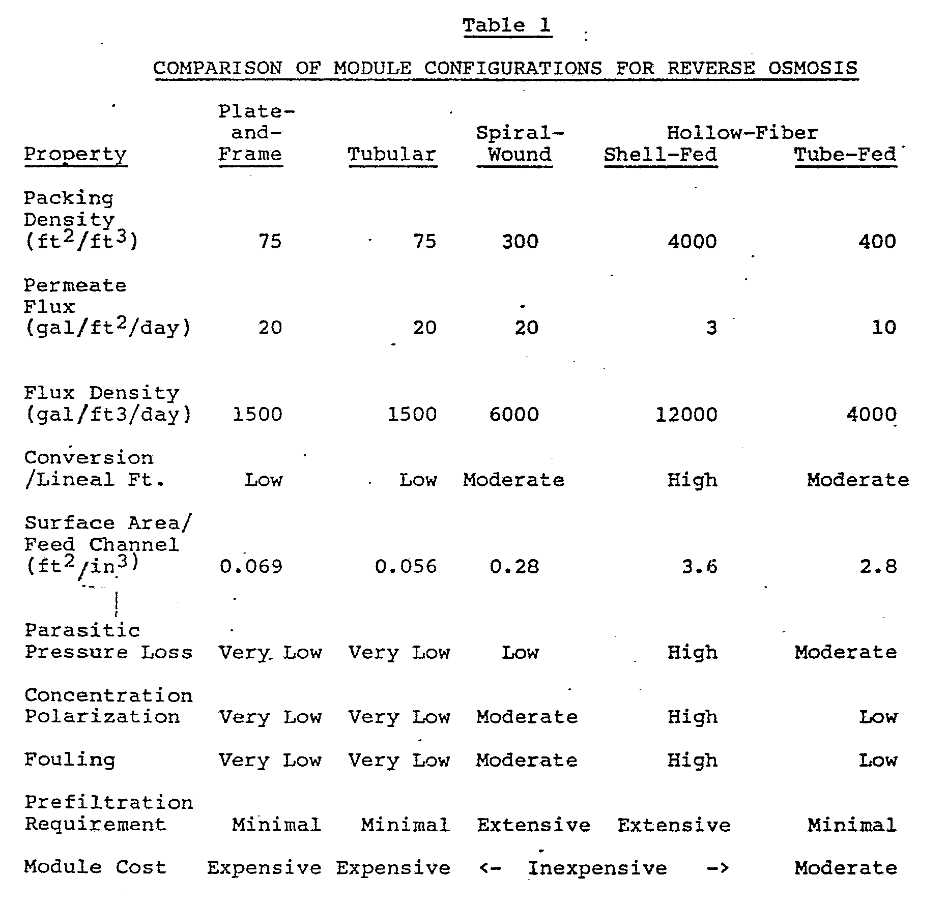
- Packing Density - The plate-and-frame and tubular modules have the least amount of membrane surface per sq. ft. and the shell-fed hollow-fiber, the most. Although increased packing density has led to other problems discussed below, the much larger surface area of the spiral-wound and hollow-fiber systems has led to their much lower cost per gallon of permeate and their overwhelming market share.
- The tube-fed hollow-fiber system is a recent entry and is comparable to the spiral-wound in packing density. However, the density shown is perhaps a practical maximum. The lumen diameter of 10 mils is at a maximum to minimize fouling and pressure drop, but is limited by the requirements for fiber-hoop strength. A large fiber thickness (30 mils) is also dictated by the required hoop strength.
- Permeate Flux - Permeate flux is dependent on rejection, pressure and osmotic pressure of the feed solution. The fluxes given are typical for brackish water feeds at 400 psi with 90-95% rejection. Hollow-fiber systems have never had the flux that has been observed in flat sheets, which offsets the higher packing density. Flux is also reduced by concentration polarization and fouling as discussed below.
- Flux Density - The spiral-wound and hollow-fiber systems have comparable flux densities whereas the plate-and-frame and tubular systems are much lower.
- Conversion/Lineal Foot - The shell-fed hollow-fiber system is the best and a four foot long module can give a conversion of 75%. A number not normally quoted but shown in Table 1 is the Surface Area/Feed Channel Volume. Combined with flux and flow rate, it gives an indication of the conversion of feed which can be expected per lineal foot. This then gives an indication of the amount of recycle or number of modules that need to be used to give adequate conversion of feed. The higher the number, the greater the conversion will be for a given flux and feed rate. It can be shown that for a given feed channel the following relationship holds true.
Conversion = K(FL/V)
where: K = a numerical constant, F = flux rate, L = module length, and V = feed rate. K increases as the Surface Area/Feed Channel Volume value increases. - Thus a higher flux rate as observed for the spiral-wound unit can offset the higher number shown for the hollow-fiber tube-fed system.
- Parasitic Pressure Loss - This is the loss which occurs to the feed as a result of going through small channels -- the smaller the channel and the longer it is, the more pressure loss. The number is least important for the shell-fed hollow fiber system due to the radial flow design involving very short distances (inches).
- However, for the other configurations it is important; and for the tube-fed hollow-fiber system, it amounts to almost 10 psi/ft. with pure water. For spiral-wound units this number is normally only 1-2 psi/ft. Pressure drop will also increase with viscosity of the feed stream. If many modules are required to achieve the requisite conversion, then repressurization will be required. The relationship of pressure loss per lineal foot to size of channel is:
Δ P = V²ρf/D
where Δ P = pressure loss/lineal ft, V.= feed rate, ρ = density, D = feed channel diameter, f = Fanning factor (dependent on Reynolds's number). - At the feed rates normally used in spiral-wound and hollow-fiber systems, f is proportional to viscosity and the reciprocals of flow diameter and density. It then follows that pressure drop is linearly related to flow, viscosity (η) and to the reciprocal of tube diameter squared as follows (Δ Pα Vη /D²). The tube-fed hollow-fiber system operates above 1.5 ft/sec. to minimize concentration polarization and would clearly benefit if larger tubes could be used.
- Concentration Polarization (Cw/Cb) - This is defined as a gradient of solute concentration at the membrane surface and is the result of a much higher flux of solvent than back diffusion of solute to the bulk solution. Polarization is most severe in shell-fed hollow-fiber systems due to the many small channels and dead spots. Although feed channels in spiral-wound systems are large, the spacer creates many dead spots. Only the plate-and-frame, tubular and tube-fed hollow-fiber systems have good positive flow without dead spots.
- Sherwood et.al [T.K. Sherwood, P.L.T. Brian, R.E. Fisher and L. Dresner, I.&E.C. Fund., 4, (1965), 2] have derived the following relationship:
Cw/Cb = exp (V(Sc)2/3/jDUb)
where: V = flux rate of solvent, Sc = Schmidt number = u/D, u = kinematic viscosity, Ub = bulk velocity, and jD = Chilton-Colburn j factor. - For turbulent flow in round tubes (not generally the case), the j factor is about f/2, where f is the Fanning friction factor. These equations suggest that conditions which exacerbate concentration polarization are high flux and low bulk velocity. Small channel diameters and large molecular weight solutes (such as found in food processing) will also increase polarization.
- Fouling - Fouling is the term applied to losses in membrane permeability due to deposition of gels and fine particulate debris that may enter with the feed, as well as precipitation of the supersaturated solute. As may be seen, the severity of the fouling problem closely parallels the concentration polarization problem. Extensive prefiltration of feed is required for spiral-wound and shell-fed hollow-fiber systems, and these systems are not readily applicable to "dirty separations" such as found in food processing. This is part of the reason for the continued market presence of plate-and-frame and tubular systems in spite of their higher cost.
- One of the main advantages claimed for the tube-fed hollow-fiber system is its anti-fouling properties achieved through the presence of unobstructed positive flow channels. Less fouling than a spiral-wound unit has been demonstrated in several tests.
- Prefiltration - As noted in the discussion of fouling, the unobstructed positive flow channels of the plate-and-frame, tubular, and tube-fed hollow-fiber systems can handle "dirty" separations and have minimal requirements for prefiltration in most applications to minimize fouling problems.
- Module Cost - When flux is compensated for, the spiral-wound and hollow-fiber systems are comparable in cost and much less expensive than the plate-and-frame and tubular systems. However, this does not represent the total costs for product water. It has been reported that prefiltration requirements of the spiral-wound and hollow-fiber shell-fed system may represent 25-40% of the total cost in water desalination. Therefore, the tube-fed hollow-fiber system could be the cheapest because of minimal pretreatment costs associated with it.
- U.S. Patent No. 2,960,462 describes the manufacture of a laminated membrane which consists of a thin layer of film of a selective membrane material mounted upon a thicker film of a membrane material having a higher permeation rate. The use of the membrane for separation processes is also described.
- U.S. Patent No. 3,580,841 discloses composite membranes having an ultrathin film barrier layer atop a microporous support, which may be used for reverse osmosis.
- U.S. Patent No. 3,401,798 describes membranes having spaces used as feed conduits which are formed by nonplanar membrane surfaces in contact with each other or in contact with a planar surface. However, the nonplanarity is not inherent in the membranes themselves, but is the result of forming laminates on a corrugated porous support. The laminates shown in Figures 2, 3, 5 and 7 of that patent have a corrugated shape which forms
spaces - U.S. Patent No. 4,206,050 discloses the use of nonplanar or profiled membrane surfaces in contact with one another where the spaces so formed between the membrane surfaces form the feed conduits. The patent relates to a membrane unit and apparatus comprising at least one permselective membrane and a fluid-absorbing and/or fluid-draining carrier containing at least one absorbent for removing metabolites from blood (Abstract of the Disclosure). The spirally wound membrane unit shown in Figure 1 comprises a profiled fluid-absorbing carrier 2 covered on both sides by a permselective membrane 1. When the fluid-absorbing carrier and thus the membrane are profiled, the spacers may be omitted (col 5., lines 47-49). When the permselective membrane 1 has no profile, a spacer, for example, in the form of a mesh net, must be provided in order to maintain a cavity through which the blood may pass (col. 5, lines 28-32). The fluid-absorbing carrier may have a profile formed by regularly distributed burls or corrugations, onto which a permselective membrane is applied on one or both sides, so that the membrane itself is profiled (col. 4, lines 27-31). Thus, as in U. S. Patent No. 3,401, 798, the permselective membrane of U.S. Patent No. 4,206,050 is not inherently grooved as in the present invention and suffers from the same deficiencies as the membranes in U.S. Patent No. 3,401,798.
- U.S. Patent No. 3,578,173 discloses a membrane containing ridges or grooves on the rear surface of a membrane formed by casting upon a grooved or ridged surface of a casting plate. The barrier layer is on the opposite surface of the membrane, i.e., the planar, non-grooved, surface. The membrane can then be supported by a nonporous backing plate, the grooves in the membrane defining channels for the liquid flow to or from the rear surface of the membrane and the membrane being held on the backing plate by a positive differential liquid pressure of the feed applied to its front planar surface (col. 1, lines 22-30). It is also disclosed that the membrane can be folded back upon itself at an angle to the grooves so that no backing plate is required and providing free passage for the (permeate) liquid. However, in the present invention, the ridges are never placed in contact at crossed angles which would limit the pressure which could be applied. In the example of the patent, the grooves were deformed when used at 500 psi.
- U.S. Patent No. 4,451,370 describes the preparation of a semipermeable membrane with regular corrugations or parallel linear ribs by casting the membrane onto a corrugated backing or by embossing a flat membrane with a corrugated pattern by applying heat and pressure thereto. The difficulties in accomplishing the former in a well controlled manner would be formidable, and generally the latter would be most difficult without significantly altering the permeability of the membrane. The patent describes a membrane separation element comprising a pair of the corrugated semipermeable membranes. The two membranes are disposed one against the other in such a manner that the parallel fluid passages defined by one of the membranes cross those defined by the other membrane (col. 1, lines 50-53). The passages for the fluid to be treated on one membrane and those on the other membrane may cross each other at an angle of about 30 to 90°, or more preferably 45 to 90° (col. 2, lines 41-44). The primary advantage claimed is that this construction ensures that the fluid to be treated is repeatedly divided and joined as it flows along the mutually crossing passages between the two membranes (col. 2, lines 7-9). It states that without the mutually crossing fluid passages, as disclosed, for example, in U.S. Patent No. 3,401,798, that the fluid entering one of the passages is confined therein until it leaves the device and as a result, the shape, dimension and the accuracy of the fluid passages have a critical bearing on the flow of the fluid (col. 4, lines 3-10).
- In direct contrast, the present invention does not have any form of crossing passages because this leads to eddies and stagnant areas of dead spots. Such areas, as is common in spiral-wound units using web spacers, have increased concentration polarization and fouling. Further, the cross mixing will lead to increased back pressure for the size of channels used. In the present invention, the shape, dimension and the accuracy of the fluid passages are well controlled.
- Briefly, the invention comprises a permeable membrane system comprised of at least two sheets, at least one of the two sheets being a permeable membrane and at least one of the two sheets having regularly spaced grooves on at least one surface, the sheets being positioned in a configuration with the grooves on the surface of one sheet forming feed channels with a surface of the covering sheet. In the preferred configurations both sheets are permeable membranes. In stacks containing several pairs of sheets, each pair may be separated with a conventional carrier cloth to transport the permeate away from the membrane surface. The grooves in the sheets are preferably about 0.5 to about 100 mils wide and deep, more preferably about 5 to about 35 mils wide and deep for reverse osmosis membranes, about 15 to about 75 mils wide and deep for ultrafiltration membranes, and about 0.5 to about 20 mils wide and deep for gas separation membranes. In one configuration of the system, the grooved sheets may be positioned so that the grooves in one sheet are aligned with the grooves in the adjacent sheet, whereby the grooves in one sheet form parts of the feed channels and the corresponding grooves of the other sheet form the other parts of the feed channels. Or, the grooved sheets may be alternated with planar sheets so that the grooves of the grooved sheets form the channels with the adjacent surface of a planar sheet. The sheet may instead be arranged with grooves for feed channels covered by the planar surface of a sheet with grooves on its other surface for a permeate channel which are parallel or perpendicular to the grooves of the sheet for the feed channels. In still another configuration, at least one of the sheets contains grooves for feed channels on one surface of the membrane and parallel or perpendicular grooves for a permeate channel on the other surface of the membrane. In the latter two cases, the carrier cloth for permeate may be omitted. Conventional membrane materials may be used to form the grooved membrane sheets. The sheets may be cast from solutions onto substrates having ridges corresponding to the grooves desired in the sheet or may be extruded from appropriately configured dies. If the membrane systems require a barrier layer, the casting may be conducted to result in an integral barrier layer on the surfaces having grooves for feed channels. Alternatively, the permeable membrane sheets may have a separately applied coating of a barrier layer on the surfaces having grooves for feed channels. In systems requiring a barrier layer, the part of the surface on the adjacent membrane sheet which will complete the feed channel also has an integral or coated barrier layer.
- The permeable membrane system is preferably made in the plate-and-frame or spiral-wound configuration. For reverse osmosis and liquid-liquid separations, the novel membrane systems of the present invention combine the advantages of conventional tubular and spiral-wound configurations without the disadvantages of either. Flux densities will be equivalent to or higher than the best conventional systems; pretreatment requirements will be minimal; fouling propensity will be low; and in the reverse osmosis process, the module costs per volume of water processed should be less than conventional spiral-wound or hollow-fibre units.
- Preferably, if there is a barrier layer on the grooved sheet, then there is also a barrier layer on the surface of the covering sheet that faces the grooved surface that has the barrier layer, if that covering sheet is permeable.
- The novel systems of this invention have unexpected properties and benefits and are useful under severe application conditions.
- It is a further object of this invention to provide novel membrane systems which do not have the distinct disadvantages of high hold-up volumes and high space requirements of the tubular and plate-and-frame systems. It is a still further object of this invention to provide a membrane system which will have the attributes of the hollow-fibre tube-fed system, but will achieve higher flux densities. These and other objects and advantages of the invention will be apparent from the specification.
- Although the membranes of the invention can be used for all the different separation and filtration processes mentioned above under the Background of the Invention, the preferred application is as a reverse osmosis membrane. For that application, the main objective is to construct a moderately high surface area membrane system which is inherently superior in controlling concentration polarization and fouling. This is done by providing for positive flow of feed solution in sufficiently large channels and by avoiding dead spots. In a positive flow system, cleaning by chemical or physical methods can also be more readily achieved.
- The module design objectives are:
- feed channels with positive flow and no obstructions,
- feed channels sufficiently large to minimize fouling,
- maximization of membrane surface area and minimization of membrane material, and
- more viable configuration for manufacture and use than the tube-fed hollow-fiber system. - The invention achieves these objectives by constructing modules based on microporous membrane sheets containing regularly spaced grooves preferably about 0.5 to about 100 mils wide and deep, and more preferably about 5 to about 35 mils wide and deep for reverse osmosis separations, about 15 to about 75 mils wide and deep for ultrafiltration and about 0.5 to about 20 mils wide and deep for gas separations. The modules are preferably of either a plate-and-frame or spiral-wound design. The grooves when covered with another membrane sheet will serve as the feed channel and will obviate the need for a feed channel spacer normally used in spiral-wound and flat-plate modules.
- Briefly, the invention comprises a novel permeable membrane system comprised of at least two sheets, at least one of the two sheets being a permeable membrane and at least one of the two sheets having regularly spaced grooves on at least one surface, the sheets being positioned in a configuration with the grooves on the surface of one sheet forming feed channels with a surface of the covering sheet. In the preferred configurations, both sheets are permeable membranes.
- The grooved sheets preferably range from about 1 mil to about 10 mils thicker than the depth of the grooves, more preferably from about 2 to about 5 mils thicker. The planar sheets preferably range from about 1 mil to about 10 mils in thickness and more preferably from about 2 to about 5 mils in thickness. The sheets may contain a supporting fabric layer such as woven polyester sailcloth or non-woven polypropylene fabric. Said fabric layers are used in many conventional membrane sheets for increased structural integrity.
- In one embodiment of the novel permeable membrane system, the grooved sheets may be positioned so that the grooves in one sheet are aligned with the grooves in the adjacent sheet, whereby the grooves in one sheet form parts of the feed channels and the corresponding grooves of the other sheet form the other parts of the feed channels.
- The invention will be further illustrated by reference to the accompanying drawings, in which:
- Fig.1 illustrates a cross-section of one configuration of the invention;
- Fig.2 illustrates a cross-section of another configuration of the invention;
- Figs.3a and 3b illustrate cross-sections of two versions of another configuration of the invention;
- Fig.4 illustrates a cross-section of yet another configuration of the invention;
- Fig.5 illustrates the cross-section of a conventional spiral-wound design for a reverse osmosis module; and
- Fig.6 illustrates a spiral-wound module prepared from a configuration having a cross-section shown in Fig.3b.
- Referring to the drawings, Fig.1 illustrates a cross-section of that
configuration 10 of the invention, in which membranes 11 each have regularly spacedgrooves 12 on one surface and barrier layers 13 on that surface of the membrane, which is intended to be in contact with the feed. When the system is in use, the feed passes through the feed channel, which are formed by the alignment and proximity of the two adjacent sets ofgrooves 12 onmembranes 11. Separating the other non-grooved surfaces 14 of the stack of membranes is a permeate carrier cloth 15, which allows the permeate to flow out of the stack ofmembranes 11 in the design. In a less preferred variation ofconfiguration 10, one of themembranes 11 in each pair can be replaced with a non-permeable grooved sheet. - The configuration is conventional in the sense that two membrane sheets are placed face-to-face, but the feed channel spacer is not needed and is eliminated. This assembly can be made into a plate-and-frame filter by incorporating the appropriate manifolds or into a spiral-wound module by applying the appropriate sealer at the edges of the permeate channel.
- In another embodiment, the feed channel grooves can be contained in one sheet and the feed channel can result from placing a planar (non-grooved) sheet in contact with it. This has the obvious advantage of not requiring the matching of the grooves between facing sheets during module assembly. For separations requiring a barrier layer on the membranes, the thin film barrier layer would be applied to only one side of the planar membrane and the front or grooved side of the other membrane. Alternatively, the feed channels could be coated after module assembly.
- Figure 2 illustrates a cross section of that
configuration 20 of the invention, in which membranes 21 each have regularly spacedgrooves 22 on one surface and barrier layers 23 on that surface of the membrane which is intended to be in contact with the feed. Covering the grooved side of eachmembrane 21 is aplanar membrane sheet 24, having abarrier layer 25 on its side adjacent tomembrane 21. When the system is in use, the feed passes through the feed channel, which results when thegrooves 22 inmembranes 21 are formed into "tunnels" by covering withplanar membrane sheets 24. Separating theother surfaces permeate carrier cloth 27, which allows the permeate to flow out of the stack of membranes in the design. In a less preferred variation ofconfiguration 20, eithermembrane 21 ormembrane 24 could be replaced with a non-permeable sheet of the same geometry. Flux density would be significantly reduced, but the other advantages would still be realized. - The order of
elements membrane 21 always facemembrane 24 surfaces forming the feed channels. - In a further embodiment, the sheets may instead be arranged with grooves for feed channels covered by the planar surface of a sheet with grooves on its other surface for a permeate channel which are parallel or perpendicular to the grooves of the sheet for the feed channels.
- Figures 3a and 3b illustrate cross sections of those
configurations 30 and 30ʹ of the invention. - In
Figure 3a membranes 31 have regularly spacedgrooves 32 on one surface and barrier layers 33 on that surface of the membrane, which is intended to be in contact with the feed. Covering the grooved side of eachmembrane 31 is anothermembrane sheet 34, having abarrier layer 35 on its planar side adjacent tomembrane 31. When the system is in use, the feed passes through the feed channel, which results when thegrooves 32 inmembranes 31 are formed into "tunnels" by covering with the planar side ofmembrane sheets 34. On the other, nonplanar, side ofmembrane sheet 34 aregrooves 36 intended for permeate, which allow the permeate to flow out of the stack of membranes in the design.Grooves 36 are aligned parallel togrooves 32. When the system is in use, the permeate passes through the permeate channels, which result when thegrooves 36 inmembranes 34 are formed into "tunnels" by covering withmembrane sheets 31. - Figure 3b shows a cross sectional cube in which membranes 31 have regularly spaced
grooves 32 on one surface and barrier layers 33 on that surface of the membrane, which is intended to be in contact with the feed. Covering the grooved side of eachmembrane 31 is a another membrane sheet 34ʹ, having a barrier layer 35ʹ on its planar side adjacent tomembrane 31. When the system is in use, the feed passes through the feed channels, which result when thegrooves 32 inmembranes 31 are formed into "tunnels" by covering with planar membrane sheets 34ʹ. On the other, nonplanar, side of membrane sheet 34ʹ are grooves 36ʹ intended for permeate, which allow the permeate to flow out of the stack of membranes in the design. Grooves 36ʹ are aligned perpendicular togrooves 32. When the system is in use, the permeate passes through the permeate channels, which result when the grooves 36ʹ in membranes 34ʹ are formed into "tunnels" by covering withmembrane sheets 31. - The designs of Figure 3a and 3b require the use of two different grooved membranes. One,
membrane 34, contains the grooves intended to be the permeate channels, and the other,membrane 31, contains the grooves intended to be the feed channel grooves. The solute rejecting barrier layer would only be coated on the planar backsides ofmembrane 34 and 34ʹ and on the front grooved side ofmembrane 31. - The configuration depicted in Figure 3b, in which the permeate channel grooves run perpendicular to the feed channel grooves, is preferred. In less preferred variations of
configurations 30 and 30ʹ, eithermembrane membrane 31 or 34ʹ respectively could be replaced with a nonpermeable membrane sheet. Although flux density would be reduced, the non-fouling attribute of the membrane systems would persist. - In still another embodiment, the sheets contain grooves for feed channels on one surface and parallel or perpendicular grooves for a permeate channel on the other surface.
- Figure 4 illustrates a cross section of the
parallel configuration 40 of the invention mentioned in the preceding paragraph, in which membranes 41 have regularly spacedgrooves 42 on one surface andparallel grooves 46 on the other surface. Barrier layers 43 are applied to those surfaces of themembranes containing grooves 42 which are intended to be in contact with the feed. Two membrane sheets are placed face-to-face to form a sandwich. When the system is in use, the feed passes through the feed channel, which is formed by the alignment and proximity of the two adjacent sets ofgrooves 42 onmembranes 41. On the other side ofmembrane sheets 41 aregrooves 46 intended for permeate, which allow the permeate to flow out of the stack of membranes in the design. Sets of the membrane sandwich are then stacked so thatgrooves 46 are aligned. When the system is in use, the permeate passes through the permeate channels, which are formed by the alignment and proximity of the two adjacent sets ofgrooves 46 onmembranes 41. - As in Figure 3b, the parallel permeate channels depicted in Figure 4 could be perpendicular to the feed channels; and this would probably be preferred. There would be added complexity in manufacturing a membrane with grooves on both sides. Again, only the sides of the membranes intended to form the feed channel would be coated with the solute-rejecting barrier layer. As with the other configurations, a less preferred variation of
configuration 40 would have nonpermeable sheets in place of one of the permeable membrane sheets. - For comparison with Figure 6, which illustrates a spiral-wound module of the invention, Figure 5 illustrates a
cross section 50 of a conventional spiral-wound design, whereinmembrane 51 has a barrier layer 53 on the side of the membrane intended to be in contact with the feed, which passes between the barrier layers 53 of two facingmembranes 51. The feed channel is formed byfeed channel spacer 52, which holds the two membranes apart a uniform distance. Separating theother surfaces 54 of the stack of membranes is apermeate carrier cloth 55, which allows the permeate to flow out of the stack of membranes in the design. - Membrane systems of the types illustrated in Figures 1 to 4 may easily be converted to spiral-wound designs. However, for the Figure 3 configuration, the 3b version would be preferred for the perpendicular placement of the permeate and feed channel grooves. Similarly, for the Figure 4 configuration, the version previously described having perpendicular placement of the permeate and feed channel grooves would be preferred.
- Figure 6 illustrates a spiral-
wound module 60 prepared from a configuration having a cross section shown in Figure 3b, in which membranes 31 have regularly spacedgrooves 32 on one surface and barrier layers 33 on that surface of the membrane, which is intended to be in contact with the feed. Covering the grooved side of eachmembrane 31 is another membrane sheet 34ʹ, having a barrier layer 35ʹ on its planar side adjacent tomembrane 31. When the system is in use, the feed passes through the feed channel, which is formed by thegrooves 32 inmembranes 31 being formed into "tunnels" by covering with planar membrane sheets 34ʹ. On the other, nonplanar, side of membrane sheet 34ʹ are grooves 36ʹ intended for permeate, which allow the permeate to flow out of the stack of membranes in the design. Grooves 36ʹ are aligned perpendicular togrooves 32. When the system is in use, the permeate passes through the permeate channels, which result when the grooves 36ʹ in membranes 34ʹ are formed into "tunnels" by covering withmembrane sheets 31. - Membrane leafs are constructed by placing membrane 34ʹ on top of
membrane 31, thereby covering thefeed channels 32 and leaving the grooves 36ʹ exposed until they are covered by being wound in the direction of the arrow under the planar bottom surface ofmembrane 31. An adhesive is placed betweenmembranes 31 and 34ʹ on the leading and trailing surfaces (although not shown these are relatively narrow surfaces on the ends parallel to permeate tube 61) and along thetop perimeter 62 of membrane 34ʹ (all four sides -- only two of which are illustrated; the other two are parallel to the permeate tube 61) so that when the leaf is rolled onto the permeate tube 61 a seal is formed along the leading edge of membrane 34ʹ to the permeate tube and on the outer edges between the grooved side of membrane 34ʹ and the planar side ofmembrane 31. These seals prevent any direct contact of feed solution with the permeate channel. The only access is permeate passing through the barrier layers and the membranes. Rolling the membrane leaf(s) onto the permeate tube is performed so that the open grooves 36ʹ of membrane 34ʹ of the first wrap are in contact with the permeate tube. Perforations or slits (not visible in the view shown) in the permeate tube form an outlet for all of these grooves at some point during the first wrap. As in conventional constructions, more than one leaf may be used with the advantage of limiting the length of permeate channels. After the leaf(s) have been bonded and wound about the permeate tube, the module structure is completed by wrapping a plastic tape around its exterior. - Spiral-wound modules having cross sections as shown in Figures 1 or 2 would be assembled as described in U.S. Patent 3,417,870 (D.T. Bray, December 24, 1968) except that no feed spacer would be required or used between the membrane surfaces which form the feed channels.
- In practice the spiral-wound element is placed in a tubular pressure vessel provided with seals (between the element and vessel) and end caps with connections for feed and product streams. The feed stream enters one end of the tubular vessel under pressure, flows through the feed channels of the element parallel to the permeate tube and across the active membrane surface, and is prevented from bypassing the membrane element by seals. The concentrated stream exits the feed channels and the end cap on the other end of the vessel. The permeate which passes through the membrane flows in a perpendicular direction through the permeate channels (or permeate carrier cloth) from the outer circumference of the element to the perforated permeate tube. The permeate then exits the tube which extends through at least one of the endcaps.
- The membrane sheets may be formed by casting, extruding or polymerizing onto a surface containing ridges corresponding to the shape and dimensions of the desired grooves in the membrane sheets.
- The casting may be conducted to result in an integral barrier layer on the surfaces having grooves for feed channels. Alternatively, the permeable membrane sheets may have a separately applied coating of a barrier layer on the surfaces having grooves for feed channels. The latter are called composite membranes.
- One method of casting the membranes is by wet casting using the phase inversion process as is generally described by Kesting [Robert E. Kesting, "Synthetic Polymeric Membranes", John Wiley & Sons, New York, (1985), pp. 251-260].
- The inclusion of pore forming materials in order to form pores in the membranes is well known from, e.g., E.K.L. Lee, W.C. Babcock, R.P. Barss, P.A. Bresnahan and M.S. Chidlaw, "Novel Composite Membranes", OWRT Contract # DI-14-34-0001-1449 to Bend Research, Inc., available from NTIS, Report # PB83-243170; L.T. Rozelle, J.E. Cadotte, R.D. Corneliussen and E.E. Erickson, "Development of New Reverse Osmosis Membranes for Desalination", OWRT Contact # DI-14-01-0001-1143 to North Star Research and Development Inst., available from NTIS, Report # PB-203-329; and R.L. Riley, G.R. Hightower, C.R. Lyons, C.E. Milstead and M.W. Milroy, "Research and Development on a Spiral-Wound Membrane System for Single-Stage Seawater Desalination", OWRT Contract # DI-14-30-3191 to UOP, Inc., Fluid Systems Dividion, available from NTIS as Report # PB81-151953. However, care should be taken to avoid conditions which result in larage formations of macrovoids especially those which protrude to the lower surface of the membrane.
- The addition of certain polymers also accomplishes the pore forming in what has been called a polymer-assisted phase-inversion process by Kesting in the aforementioned reference (p.264). A preferred polymer is polysulfone. Udel® polysulfone from Union Carbide or Victrex® polyether sulfone from ICI America are suitable examples and have been used by many others for this purpose. Other suitable polymers include cellulose esters, polystyrene, polyvinyl butyral, chlorinated polyvinyl chloride, polyvinylidene fluoride, diphenylolpropane polycarbonate, polymethyl methacrylate, or poly(m-phenylene isophthalamide) and the like. A fabric support may also be included.
- An alternative process is to use a thermal phase inversion technique recently described by Anthony J. Castro in U.S. Patent No. 4,247,498, Jan. 27, 1981.
- This technique would be preferable for making membrane sheets with an integral barrier layer because a dense skin can form on the casting, i.e., grooved surface. (This is not the case for the wet casting method, where the dense skin, if formed, is on the opposite surface, i.e., the side away from the casting plate.) The thermal phase-inversion process utilizes a latent solvent, which is a solvent at a higher temperature and becomes a nonsolvent at a lower temperature. The process is applicable to many polymers and is particularly suited to those polymers which, because of their low solubility, are not suitable for the wet casting approach. Examples of these are the polyolefins. Ex amples of suitable polymers and appropriate solvents are given in U.S. Patent No. 4,247,498 and include polypropylene with N,N-bis(2-hydroxyethyl)tallowamine, low density polyethylene with 1-octanol, polymethyl methacrylate with 1,4-butanediol, and the like. This process has also recently been described by Caneba and Soong using polymethyl methacrylate and dioxolane solvent [G.T. Caneba and D.S. Soong, "Polymer Membrane Formation - Thermal-Inversion Process. I. Experimental Study of Membrane Structure Formation", Macromol., 18, (1985), 2538; and G.T. Caneba and D.S. Soong, "Polymer Membrane Formation - Thermal-Inversion Process. II. Mathematical Modeling of Membrane Structure Formation", ibid., 2545].
- Another method to form the membrane sheets of this invention would be to thermally form the grooves in sheets containing extractable salts. Melt extrusion of a mixture of polyvinyl chloride and micronized sodium chloride may be used for this purpose [B. Baum, R.A. White and J. Labis, "Development of Porous Polyvinyl Chloride Coated Tubulets for Seawater Desalination", OWRT Contract # DI-14-30-3250 to DeBell and Richardson, Inc., available from NTIS, Report # PB-243 278/9].
- Another optional process for preparing the membranes of the invention would be to polymerize and crosslink a solution of monomers in the presence of a nonreactive solvent to produce a microporous structure. An example of this technique may be found in a recent patent assigned to Gelman Sciences Technology Ltd. [G.B. Tanny, "Method for Manufacturing Microporous Membrane", U.S. Patent 4,466,931, August 5, 1982.]
- For applications of reverse osmosis, gas separation, and liquid-liquid separations, a barrier layer will normally have to be applied to those surfaces making up the feed channel. Most of the known methods can be used and as described on page 277 in the referenced text by Kesting include: application of a preformed polymer or prepolymer solution directly onto the porous support followed by drying or curing; interfacial polycondensation of reactive monomers on the surface of the membrane; lamination of a separately cast ultra thin film; and plasma polymerization of suitable monomers onto the membrane surface. Only the first two methods however, have achieved any practical significance.
- An example of the first method is the application of a polyethyleneimine prepolymer as a dilute aqueous solution to the surface of the membrane followed by a subsequent reaction with toluene diisocyanate in a hexane solution to form a crosslinked polyurea and finally thermal curing to result in what is known as the NS-100 membrane [J.E. Cadotte, "Reverse Osmosis Membrane", U.S. Pat. 4,039,440, August 2, 1977, and L.T. Rozelle, J.E. Cardotte, K.E. Cobian and C.V. Kopp, "Nonpolysaccharide Membranes for Reverse Osmosis: NS-100 Membranes", S. Sourirajan, Ed., National Research Council Canada, Ottawa, Ontario, Canada, (1977), 249-261].
- An example of the second method is the formation of an interfacial polymer by the application of a dilute aqueous solution of m-phenylene diamine to the membrane surface followed by contact with a hexane solution of trimesoyl chloride. A lightly crosslinked aromatic polyamide coating results, yielding what is known as the FT-30 membrane, which has been described in U.S. Pat. 4,277,344, J. Cadotte, 1981.
- The barrier layer can be applied in one of several ways. First, it can be applied to the suitable membrane surfaces prior to the assembly of the membrane element. Secondly, the coating can be applied to the feed channels after assembly of the element in a manner similar to that employed by workers at Bend Research, Inc. to coat the inside of hollow-fibers after module assembly. A useful modification might be to apply the prepolymer or one of the reactive monomers prior to module assembly and to perform the polymerization or curing after module assembly. Another method described on page 281 of the Kesting reference, as the reverse sequence, would be to form the thin film prior to formation of the microporous support. Two methods are described: first, where the thin film is formed on the casting substrate prior to casting of the membrane support, and second, where the thin film is formed on a microporous membrane precursor which is ultimately formed (after coating with the thin film) by extraction or leaching of certain components present during the casting of the membrane support.
- There are many variations possible regarding the spacing of the grooves, their size and their shape. The trade-offs will be to maximize the membrane surface area, minimize concentration polarization and fouling, minimize pressure drops, maintain structural integrity and simplify manufacturing.
- The shape of the cross section of the channel will in part be dictated by the type of assembly. Thus a circular cross section is possible with the type depicted in Figure 1, but would be very difficult with the other types. It is assumed that a circular cross section would be ideal and that as close to circular as possible would be the best.
- The size of the feed channel cross section will depend only on the thickness of the membrane and what is optimum for the flow requirements, i.e., flow velocity and minimal pressure loss. The actual surface area of a membrane as seen by the feed channel, for a given membrane sheet will be independent of cross section size provided that the spacing of the channels is a function of the cross section width or diameter. Thus, for square cross sections, the area of membrane surface in the feed channels is given by the following expression:
Surface Area = 4WL/F
where: W = width of area with grooves, L = length of membrane, and F = spacing factor (F = 2 where spacing is twice the width of the cross sections and F = 3/2 where spacing is 3/2 the width of the cross sections) - For circular cross sections, the formula is:
Area = ΠWL/F
where W, L, F have the same meanings as above. Similar formulas can be derived for other shapes of cross sections. - The determining factors in establishing the feed channel surface area in a module will thus be the combined thicknesses of membranes, and permeate cloth if used, to form 1 layer of feed and permeate channels, and the spacing between the feed channels. The surface area of membrane in the feed channel per cubic foot of module (packing density) is then given by:
Area per cu.ft. = (S/F)(12,000/T)
where: S = shape factor (circle = Π, square = 4), F = spacing factor; T = thickness in mils of membranes (and cloth) in 1 layer of feed and permeate channels. - The greatest interest for reverse osmosis will be using about 20 mil grooves at spacing factors between 1.5 and 2. This results in packing densities between 500 and 1000 ft²/ft³. Smaller channels such as might be appropriate in gas separations can obviously lead to much larger packing densities.
- A further feature of the design of the invention not easily attained with the prior art systems would be to use tapered grooves. Decreased velocity of flow in the upstream end of modules leads to increased fouling and concentration polarization. This is easily understood in the practical situation where conversion of feed to permeate is high (30 to 75%). Writing about ultrafiltration, A. Michaels has stated: "Probably the most serious limitation is the inescapable problem of permeation flux depression by solute polarization at the upstream membrane surfaces. This phenomenon causes a 10-fold or greater reduction in membrane hydraulic permeability relative to the measured pure-water permeation rate, along with a marked negative dependence of permeability on the concentration of retained solutes in the upstream field." [A. Michaels, "Ultrafiltration: An Adolescent Technology," Chemtech, January 1981, 36-43.] Grooves tapered down to the exit side could be tailored to have flow velocity constant for a given conversion. For example, with square cut grooves, the changes indicated in Table 2 would provide for constant flow velocity at the stated conversions.

- The membrane systems of the invention may be used for the separations mentioned herein.
- Generally, the invention also comprises a process for the separation of one component from a mixture comprised of at least two components which comprises applying sufficient pressure to the mixture to cause one component to pass through a permeable membrane system comprised of at least two permeable membrane sheets, at least one of the two sheets having regularly spaced grooves on at least one surface, the sheets being positioned in a configuration with the grooves on the surface of one sheet forming feed channels with a surface of the covering sheet, thereby resulting in a solvent-rich permeate stream enriched in one component and a residual stream enriched in the remaining components of the original mixture.
- Preferably, the process utilizes the preferred embodiments of the membrane system mentioned herein.
- More particularly, the invention comprises a process for reverse osmosis separation of solvent from a solution comprised of a solvent and a solute which comprises applying sufficient pressure to the solution to overcome the osmotic pressure of the solution and thereby cause the solvent to pass through a permeable membrane system comprised of at least two permeable membrane sheets, at least one of the two sheets having regularly spaced grooves on at least one surface, the sheets being positioned in a configuration with the grooves on the surface of one sheet forming feed channels with a surface of the covering sheet, thereby resulting in a solvent-rich permeate stream and a solute-rich residual stream.
- There are several advantages to the invention. Module properties for the invention in reverse osmosis, which show these advantages, are listed in Table 3 along with the properties of the high flux-density modules previously listed in Table 1.

- The following combination of properties should make the invention the configuration of choice for most separations and especially for feed streams with significant concentrations of suspended matter.
- Flux density equivalent to or higher than shell-fed hollow-fiber modules.
- Low fouling compared to the readily fouled conventional spiral-wound and hollow-fiber modules and probably better than the tube-fed hollow-fiber module as well.
- Minimal prefiltration requirement.
- A module cost per volume of water processed less than any of the other modules. - A more detailed discussion of the properties in reverse osmosis applications follows:
- The packing density of the invention will be primarily a function of the feed channel membrane thickness and groove spacing. However, it is expected that the density will easily exceed that of the conventional spiral-wound and the tube-fed hollow-fiber modules, but never achieve that of the shell-fed hollow-fiber module. For instance, using a
feed channel membrane 25 mil thick, a permeate channel membrane 15 mil thick, 20 mil wide grooves, and a spacing factor of 2, the packing density will be 600. Changing the spacing factor to 3/2 will result in a density of 800. These numbers will be reduced slightly by the volume of the permeate tube (ca. 7%). - Flux should approximate the maximum attainable, should easily be equivalent to that achieved in flat membrane sheets, and could exceed that observed in spiral-wound modules. A number of 20 gfd is used, which is easily achieved with composite membranes at 400 psi, and is consistent with the numbers used in Table 1. Using tapered channels, the flux at high conversions could exceed that observed for any other system.
- Flux density should exceed that of all other systems.
- Surface Area/Feed Channel Volume for the 20 mil grooves is clearly better than the spiral-wound system and not quite as good as the tube-fed hollow-fiber system. However, the higher flux will result in comparable conversions per lineal foot.
- The parasitic pressure loss should be low compared to either of the hollow-fiber types, and probably equivalent to other spiral-wound configurations.
- Concentration polarization should be less than for the other high density systems. This is a result of two factors -- the absence of dead spots caused by protrusions in the feed channel and the relatively large size channels.
- Fouling is also expected to be less than for any of the other high density systems for the same reasons stated above. Evidence that this should be true lies in the work carried out at Bend Research for reverse osmosis with tube-fed hollow-fiber modules. Their modules contain lumens of about 10 mil in diameter, and were shown to behave in a superior manner to a conventional spiral wound module. However, the lumen size of their modules is limited by the requirements for hoop strength --a requirement not present in this invention. It is expected that grooves about 20 mil in width will be superior in non-fouling properties to their tube-fed hollow-fiber system. The performance of the systems of the invention should approximate that of the plate-and-frame and tubular systems, and should permit the handling of "dirty" separations. The positive flow of feed should also permit easy and effective cleaning.
- Prefiltration requirements for the tubular modules are minimal, which has been a deciding factor in their application to "dirty" separations. The spiral-wound units require extensive prefiltration to prevent rapid fouling, and the shell-fed hollow-fiber modules are the worst in terms of fouling. As noted above, the large lumen tube-fed hollow-fiber modules being developed by Bend Research appear to require minimal prefiltration and the same should be true for the present invention.
- Cost on a square foot basis of active membrane of the invention is expected to be less than that for the spiral-wound membrane. It is roughly estimated that per square foot of membrane material the costs may be 50% higher. However, because there will be at least twice as much surface area per square foot of material, the costs on an active membrane area basis will be at least 25% less.
- The additional savings on pretreatment costs over the other "low cost" systems should give the invention a clear advantage.
- The invention also comprises a process for ultrafiltration of liquid from a mixture comprised of a liquid and either a large molecular weight solute or suspended particles or both which comprises applying sufficient pressure to the mixture to cause the liquid to pass through a permeable membrane system comprised of at least two permeable membrane sheets, at least one of the two sheets having regularly spaced grooves on at least one surface, the sheets being positioned in a configuration with the grooves on the surface of one sheet forming feed channels with a surface of the covering sheet, thereby resulting in a liquid-rich permeate stream and a residual stream enriched in the remaining components of the mixture.
- The invention further comprises a process for the separation of one gas from a mixture comprised of at least two gases which comprises applying sufficient pressure to the mixture to cause a measurable flux of at least one gas through a permeable membrane system comprised of at least two permeable membrane sheets, at least one of the two sheets having regularly spaced grooves on at least one surface, the sheets being positioned in a configuration with the grooves on the surface of one sheet forming feed channels with a surface of the covering sheet, thereby resulting in a permeate stream enriched in one gas and a residual stream enriched in the remaining gases of the original mixture.
- The invention still further comprises a process for liquid-fluid separation of the fluid from a mixture of (a) a liquid and (b) a fluid which is either a liquid or a gas, which process comprises applying sufficient pressure to the solution to overcome the osmotic pressure of the solution and thereby cause the fluid to pass through a permeable membrane system comprised of at least two permeable membrane sheets, at least one of the two sheets having regularly spaced grooves on at least one surface, the sheets being positioned in a configuration with the grooves on the surface of one sheet forming feed channels with a surface of the covering sheet, thereby resulting in a permeate stream rich in fluid (b) and a residual stream enriched in liquid (a).
- The invention still further comprises a continuous process for separating product from fluid reactants and catalyst in a reactor system wherein the catalyst is attached or immobilized onto a permeable membrane or an adjacent surface or is recirculated with reactants across the surface of the permeable membrane and the separation is effected by the ability of the product to selectively pass through a permeable membrane system comprised of at least two permeable membrane sheets, at least one of the two sheets having regularly spaced grooves on at least one surface, the sheets being positioned in a configuration with the grooves on the surface of one sheet forming feed channels with a surface of the covering sheet, thereby resulting in a product-rich permeate stream and a reactant-rich residual stream, which is recirculated through the reactor with additional reactants.
- The following examples describe the manner and process of making and using the invention and set forth the best mode contemplated for carrying out the invention, but are not to be construed as limiting.
- A casting solution comprising 20% (wt./wt.) of Victrex® polyethersulfone (ICI Americas - Grade 4800P), 16% (wt./wt.) 2-methoxyethanol, commonly known as methylcellosolve (Aldrich Chemical Co.), and 1% (wt./wt.) 2,4-diamino-6-phenyl-S-triazine (Eastman Kodak Co.) is mixed with 63% (wt./wt.) N,N-dimethylacetamide (DMAc) (J.T. Baker Chemical Co.) with agitatioin and mild heat until dissolved. The resulting solution is filtered and deaerated of entrained bubbles by allowing it to stand in a closed container overnight at room temperature.
- A continuous grooved membrane sheet is prepared by casting the polyethersulfone solution onto a grooved roll using a doctor knife set at a 10 mils clearance between knife edge and roll surface. The grooved roll is 12 inches in diameter and 48 inches in length and has
circumferential grooves 20 mil wide and 20 mils deep cut into the roll surface and spaced 20 mils apart. The grooved roll is partially immersed (1/2 the roll) in a coagulating bath for the polyethersulfone consisting of 50/50 (wt./wt.) DMAc/H₂O at room temperature. The grooved roll rotates at a circumferential speed of approximately 4 inches/min, thus providing for an immersion or coagulating time of about 5 minutes. The wet, coagulated, grooved film is continuously withdrawn from the roll and coagulating bath and passes through a series of additional baths of 25/75 and 10/90 DMAc/H₂O, and 100% water for final washing to remove residual DMAc solvent and then dried continuously in a drying chamber to remove water. In a similar manner, a planar membrane sheet is prepared using a smooth roll in place of the grooved roll. The total membrane thicknesses of the grooved sheet and of the planar sheet are approximately 25 and 5 mils respectively. - The grooved side of the dried membrane from the previous example is coated with an 0.3% aqueous solution of polyethyleneimine (Epomin® P1000) (Aceto Chemical Co.) and 10% of polyoxyethylene glycol (Carbowax® PEG - 6000). It is subsequently coated with an 0.15% solution of toluene-2,4-diisocyanate (Aldrich Chemical Co.) in hexane. The interfacially polymerized coating is cured for 15 min at 115° C. Although ideally this process can be carried out continuously, in this example it is done batchwise with appropriately sized sheets.
Sheets 20 inches in width and 48 inches long are cut from the coated continuous membrane sheet so that the grooves run perpendicular to the length of the resulting sheet. In a similar manner, the planar membrane prepared in Example I is also coated. - Sheets of the thin film coated membranes from Example II are fabricated into a reverse osmosis element as follows. A porous resin impregnated tricot product channel material, commonly known as permeate carrier cloth (Resource Technology, Inc.) is first attached to a perforated hollow mandrel tube with an adhesive. The membrane sandwich consisting in this instance of a 42 inch by 20 inch sheet of the grooved membrane and a similar size sheet of smooth membrane with the coating or active membrane surfaces of the two sheets facing one another is placed on the tricot so that the grooves are parallel to the mandrel. Polyurethane adhesive (UR2166 - H.B. Fuller Co.) is applied between the leading edges of the membranes and to the back (non-active) side of both membranes along the long edges and the edge of the trailing short sides of the membranes. The element is then rolled up by rotating the mandrel to form the spiral wound element with alternating layers of tricot and membrane sandwich. The exterior of the element is then wound with a layer of plastic tape over the membrane surface. After the adhesive has cured (overnight at room temperature), it is then ready for test and use in reverse osmosis. The ends of the spiral wound element are trimmed to the mandrel surface to expose the feed channel edges and sealed edges of the product channel. The sealed envelope of the membrane sandwich thus allows for product flow to the mandrel tube without communicating with the feed flow from the exposed ends of the grooved channels. The device has a total of about 10 square feet of membrane.
- To form a prior art membrane system, a similar 10 square foot spiral-wound element is fabricated in a like manner from two planar membrane sheets except that a plastic netting (Vexar®) is placed between the membrane sandwich so that the netting is between the active layers of the two membrane sheets. The netting thus functions to provide for feed channel flow across the membrane's active surfaces.
- The two spiral-wound elements of the previous example are placed in separate tubular pressure vessels provided with mandrel seals and end caps and with connections for feed and product streams.
- The grooved and the planar spiral-wound elements are tested simultaneously for fouling resistance by arranging the two pressure vessels containing the respective spiral-wound elements in a parallel flow configuration in a pressure flow test apparatus. The units are tested with a 0.5% (wt./wt.) solution of sodium chloride in water containing 3000 ppm of suspended kaolin clay. The feed rates are adjusted to give a linear flow rate of 0.5 meters/sec. (1.5 ft/sec) to each module based on the dimension of the feed channel spacings.
- Initial measurements at 400 psi indicate a flux or product flow of about 15 gfd and 95% rejection for both modules. However, over a 24 hour period, the spiral-wound planar membrane module tends to foul as shown by a large drop in flux and rejection. By contrast, the grooved membrane module exhibits essentially no change in performance. Thus the efficiency of grooved membranes to fouling is demonstrated.
- A spiral-wound element is made in the same manner as in Example III except that the uncoated microporous membrane sheets from Example I are used. The element is placed in a tubular pressure vessel provided with mandrel seals and end caps and with connections for feed and product streams.
- The unit is tested at 50 psi with an aqueous solution containing 1000 ppm of sodium chloride and 200 ppm polyoxyethylene glycol of 6000 molecular weight. At a feed rate of about 75 gal/hr., the initial flux will be about 600 gal/day (60 gal/ft²/day). The rejection of sodium chloride will be about 0% and the rejection of polyoxyethylene glycol will be about 80%.
- A continuous grooved polyethersulfone membrane sheet and a planar membrane sheet are made as described in Example I except that the grooved roll contains circumferential grooves 5 mils wide and 5 mils deep and spaced 5 mils apart, and the doctor knife is set at a clearance of 5 mils between the knife edge and roll surface.
- One surface of the dried planar membrane and the grooved surface of the dried grooved membrane sheet, which surfaces together comprise the feed channels, are passed through a trifluorotrichloroethane solvent containing 1.5 wt.% of dimethyl silicone and 0.15 wt.% of a crosslinking agent comprising dibutyl tin dilaurate. The process is described in U.S. Patent No. 4,243,701. The membranes are passed through said solution at ambient temperature and atmospheric pressure and are withdrawn at a rate of 4 cm/sec. Thereafter the dimethyl silicone is cross-linked by treatment at a temperature of 120°C for a period of 0.25 hour to form a thin polymeric film integrally bonded to the supporting membrane, said thin polymeric film having a thickness of about 5000 Angstroms.
- A spiral-wound module is made using the membrane sheets from Example VI by the same procedure used in Example III. The element is then used in a single-stage gas-separation process. A feed stream comprising air is passed over the surface of this membrane at a pressure of 150 psi at 25°C. The membrane exhibits a higher permeability to oxygen than to nitrogen, and the permeate stream, which passes through the membrane, is enriched in oxygen, while the residue stream, which consists of the remainder of the unpermeated stream, is enriched in nitrogen. It is possible to attain oxygen enrichments of the permeate stream to as high as 35%.
Claims (22)
Applications Claiming Priority (2)
| Application Number | Priority Date | Filing Date | Title |
|---|---|---|---|
| US06/901,827 US4756835A (en) | 1986-08-29 | 1986-08-29 | Permeable membranes having high flux-density and low fouling-propensity |
| US901827 | 1986-08-29 |
Publications (2)
| Publication Number | Publication Date |
|---|---|
| EP0259109A2 true EP0259109A2 (en) | 1988-03-09 |
| EP0259109A3 EP0259109A3 (en) | 1988-08-17 |
Family
ID=25414880
Family Applications (1)
| Application Number | Title | Priority Date | Filing Date |
|---|---|---|---|
| EP87307630A Withdrawn EP0259109A3 (en) | 1986-08-29 | 1987-08-28 | Permeable membranes having high flux-density and low fouling propensity and processes including their use |
Country Status (3)
| Country | Link |
|---|---|
| US (1) | US4756835A (en) |
| EP (1) | EP0259109A3 (en) |
| JP (1) | JPS6369503A (en) |
Cited By (16)
| Publication number | Priority date | Publication date | Assignee | Title |
|---|---|---|---|---|
| WO1989004865A1 (en) * | 1987-11-16 | 1989-06-01 | Horst Chmiel | Device for culturing cells immobilized in a bioreactor |
| EP0411658A2 (en) * | 1989-08-04 | 1991-02-06 | Mitsubishi Rayon Co., Ltd | Method for culturing cells |
| GB2236693A (en) * | 1989-08-16 | 1991-04-17 | Foseco Int | Filtration |
| FR2696653A1 (en) * | 1992-10-09 | 1994-04-15 | Lescoche Philippe | Inorganic filtration unit comprising at least one integrated circulation network of a liquid medium to be treated and / or of the recovered filtrate. |
| EP0599791A2 (en) * | 1992-11-27 | 1994-06-01 | Aktiebolaget Electrolux | A method of manufacturing a membrane filter |
| US5378369A (en) * | 1993-02-11 | 1995-01-03 | Sasol Chemical Industries (Proprietary) Limited | Solvent extraction |
| GB2275626B (en) * | 1993-02-11 | 1996-10-23 | Pall Corp | An affinity separation device and its use for immunoglobulin separation |
| WO1997043633A1 (en) * | 1996-05-17 | 1997-11-20 | Encelle, Inc. | Electrochemical biosensors |
| US5922339A (en) * | 1998-01-27 | 1999-07-13 | Usala; Anton-Lewis | Compositions and methods for biocompatible implants |
| DE102005042457A1 (en) * | 2005-09-06 | 2007-03-22 | Oase Gmbh | Water purification equipment for ponds or similar water bodies, comprises housing, fine filter arranged downstream to coarse strainer and also within the housing, pump for transporting the water towards discharge port of the housing |
| WO2011005657A1 (en) * | 2009-07-09 | 2011-01-13 | Dow Global Technologies Inc. | Spiral wound module including membrane sheet with capillary channels |
| NL2004510C2 (en) * | 2010-04-06 | 2011-10-10 | Redstack B V | Membrane stack for a membrane based process and a device and method therefor. |
| EP2551010A1 (en) * | 2010-03-23 | 2013-01-30 | Toray Industries, Inc. | Separation membrane and method for producing same |
| EP2659952A1 (en) * | 2010-12-28 | 2013-11-06 | Toray Industries, Inc. | Separation membrane element |
| WO2014135295A1 (en) * | 2013-03-04 | 2014-09-12 | Robert Bosch Gmbh | Component for oxygen enrichment, component stack, device for obtaining a fluid enriched with oxygen, metal-oxygen battery and motor vehicle |
| EP2889076A1 (en) * | 2013-12-04 | 2015-07-01 | Pall Corporation | Membrane with surface channels |
Families Citing this family (79)
| Publication number | Priority date | Publication date | Assignee | Title |
|---|---|---|---|---|
| NL8702149A (en) * | 1987-09-09 | 1989-04-03 | Tno | MEMBRANE MODULE FOR HYPERFILTRATION OR ULTRAFILTRATION OF POLLUTION LIQUID FLOWS. |
| US5232589A (en) * | 1987-10-02 | 1993-08-03 | Kopf Henry B | Filter element and support |
| JP2830080B2 (en) * | 1988-07-08 | 1998-12-02 | 株式会社デンソー | Filter element and manufacturing method thereof |
| US4842736A (en) * | 1988-09-06 | 1989-06-27 | Desalination Systems, Inc. | Spiral wound membrane |
| JP3033109B2 (en) * | 1990-01-25 | 2000-04-17 | 株式会社デンソー | Filter element and manufacturing method thereof |
| US5096586A (en) * | 1990-08-28 | 1992-03-17 | Regents Of The University Of California | Membranes having selective permeability |
| US5271843A (en) * | 1991-09-09 | 1993-12-21 | Allied-Signal Inc. | Chlorine-tolerant, thin-film composite membrane |
| US5282968A (en) * | 1992-08-03 | 1994-02-01 | E. I. Du Pont De Nemours And Company | Process for separating and recovering halocarbons from mixtures thereof |
| US5456841A (en) * | 1992-08-03 | 1995-10-10 | E. I. Du Pont De Nemours And Company | Process for separating and recovering halocarbons from mixtures thereof |
| US5739005A (en) * | 1995-03-17 | 1998-04-14 | Auburn University A Public University Of The State Of Alabama | Use of polymeric films for delivery of nematode eggs and ecological evaluations |
| US6514412B1 (en) * | 1998-06-18 | 2003-02-04 | 3M Innovative Properties Company | Microstructured separation device |
| US7316780B1 (en) | 1999-01-29 | 2008-01-08 | Pall Corporation | Range separation devices and processes |
| AU3583900A (en) * | 1999-01-29 | 2000-08-29 | Pall Corporation | Separation devices and processes |
| CO5241319A1 (en) * | 1999-03-29 | 2003-01-31 | Garfield Int Invest Ltd | INVERTED OSMOSIS CARTRIDGES AND INVERTED OSMOSIS MEMBRANES |
| WO2002020142A1 (en) | 2000-09-05 | 2002-03-14 | Miox Corporation | Reverse osmosis membrane and process for making same |
| US6632357B1 (en) | 1999-11-18 | 2003-10-14 | University Of South Florida | Reverse osmosis (“RO”) membrane system incorporating function of flow channel spacer |
| US6361588B1 (en) * | 1999-12-22 | 2002-03-26 | Jose Moratalla | Selective permeability energy recovery device |
| JP4712181B2 (en) * | 2000-11-21 | 2011-06-29 | 株式会社アイラー千野 | Rotary evaporator |
| DE10138319A1 (en) * | 2001-08-10 | 2003-04-24 | Geesthacht Gkss Forschung | Membrane body and method for producing the same |
| DE10139830A1 (en) * | 2001-08-14 | 2003-02-27 | Roche Diagnostics Gmbh | Flat sheet membrane, for filtration, has channel apertures five times larger than membrane nominal pore size |
| US20050092175A1 (en) * | 2003-10-29 | 2005-05-05 | Meacham G.B. K. | Noble metal gas barriers |
| US7074255B2 (en) * | 2003-10-29 | 2006-07-11 | Meacham G B Kirby | Noble metal gas barriers |
| AU2005294236A1 (en) | 2004-10-06 | 2006-04-20 | Home Dialysis Plus, Ltd. | Mecs dialyzer |
| US7955504B1 (en) | 2004-10-06 | 2011-06-07 | State Of Oregon Acting By And Through The State Board Of Higher Education On Behalf Of Oregon State University | Microfluidic devices, particularly filtration devices comprising polymeric membranes, and method for their manufacture and use |
| US7341663B2 (en) * | 2004-12-16 | 2008-03-11 | The United States Of America As Represented By The Secretary Of Agriculture | Spiral-wound liquid membrane module for separation of fluids and gases |
| SE530221C2 (en) * | 2005-02-28 | 2008-04-01 | Alfa Laval Corp Ab | Spiral wound membrane module with spacer element for permeate |
| US20060219635A1 (en) * | 2005-03-30 | 2006-10-05 | Special Membrane Technologies, Inc. | High-density filtration module |
| JP2007105644A (en) * | 2005-10-14 | 2007-04-26 | Hitachi Ltd | Operation controller and operation support device of membrane filtration apparatus |
| US20070095756A1 (en) * | 2005-10-31 | 2007-05-03 | General Electric Company | System and method for removal of contaminants from feed solution |
| US20090139650A1 (en) * | 2005-10-31 | 2009-06-04 | General Electric Company | Reverse osmosis membrane and membrane stack assembly |
| US8083936B1 (en) | 2008-03-03 | 2011-12-27 | Robert Walker | Reducing waste water in reverse osmosis residential drinking water systems |
| US8043512B2 (en) * | 2008-04-11 | 2011-10-25 | Pall Corporation | Fluid treatment arrangements and methods |
| DE102008030447A1 (en) * | 2008-06-26 | 2009-12-31 | Dimension-Polyant Gmbh | sail membrane |
| DE102008030446A1 (en) * | 2008-06-26 | 2009-12-31 | Dimension-Polyant Gmbh | sail membrane |
| US8048315B2 (en) * | 2008-07-28 | 2011-11-01 | Pall Corporation | Fluid treatment arrangements and methods |
| JP2010099590A (en) * | 2008-10-23 | 2010-05-06 | Nitto Denko Corp | Sheet-like composite semi-permeable membrane and manufacturing method therefor |
| WO2011004786A1 (en) * | 2009-07-06 | 2011-01-13 | 積水化学工業株式会社 | Polymer membrane for water treatment |
| US8241495B2 (en) * | 2009-08-28 | 2012-08-14 | Dow Global Technologies Llc | Filtration module including membrane sheet with capillary channels |
| US8753515B2 (en) | 2009-12-05 | 2014-06-17 | Home Dialysis Plus, Ltd. | Dialysis system with ultrafiltration control |
| CA2786008C (en) * | 2009-12-31 | 2018-02-06 | Joseph L. Charest | Microfluidic device facilitating gas exchange, and methods of use and manufacture thereof |
| US9492792B2 (en) * | 2010-04-20 | 2016-11-15 | Fibracast Ltd. | Formed sheet membrane element and filtration system |
| US8580161B2 (en) | 2010-05-04 | 2013-11-12 | State Of Oregon Acting By And Through The State Board Of Higher Education On Behalf Of Oregon State University | Fluidic devices comprising photocontrollable units |
| JP2013534461A (en) | 2010-05-26 | 2013-09-05 | ザ チャールズ スターク ドレイパー ラボラトリー インク | Micromachined artificial lung assist device and methods of use and manufacture thereof |
| US8501009B2 (en) | 2010-06-07 | 2013-08-06 | State Of Oregon Acting By And Through The State Board Of Higher Education On Behalf Of Oregon State University | Fluid purification system |
| DE102010027689A1 (en) * | 2010-07-20 | 2012-01-26 | Siemens Aktiengesellschaft | Module for separating mixtures of substances and corresponding method |
| JP5817330B2 (en) * | 2010-08-24 | 2015-11-18 | 東レ株式会社 | Separation membrane and separation membrane element |
| US20140090450A1 (en) * | 2011-03-28 | 2014-04-03 | Imperial Innovations Limited | Test Rig And Method For Simulating And Analyzing Petrochemical Fouling |
| CN103648621B (en) * | 2011-07-07 | 2017-09-15 | 东丽株式会社 | The manufacture method of seperation film, separating film element and seperation film |
| WO2013052680A2 (en) | 2011-10-07 | 2013-04-11 | Home Dialysis Plus, Ltd. | Heat exchange fluid purification for dialysis system |
| EP2768604A4 (en) | 2011-10-20 | 2015-09-02 | Fibracast Ltd | Coating device and process for coating formed sheet membrane element |
| JP6395608B2 (en) | 2011-12-05 | 2018-09-26 | ザ チャールズ スターク ドレイパー ラボラトリー インク | Method for reducing blood injection volume and membrane surface area in a microfluidic lung assist device |
| DE102012008197B4 (en) * | 2012-04-26 | 2018-06-14 | Al-Ko Therm Gmbh | Exchange system for the exchange of substances between two fluids |
| KR102162325B1 (en) | 2012-12-21 | 2020-10-06 | 포리페라 인코포레이티드 | Separation systems, elements, and methods for separation utilizing stacked membranes and spacers |
| WO2018057474A1 (en) | 2016-09-20 | 2018-03-29 | Aqua Membranes Llc | Permeate flow patterns |
| CN105188889B (en) | 2013-03-15 | 2018-01-19 | 波里费拉公司 | The development of osmotic drive membrane system comprising low voltage control |
| JP5946220B2 (en) * | 2013-03-26 | 2016-07-05 | 富士フイルム株式会社 | Complex for acid gas separation, module for acid gas separation, and method for producing module for acid gas separation |
| US9717835B2 (en) | 2014-04-23 | 2017-08-01 | The Charles Stark Draper Laboratory, Inc. | Blood oxygenator |
| WO2015168280A1 (en) | 2014-04-29 | 2015-11-05 | Outset Medical, Inc. | Dialysis system and methods |
| WO2015183103A2 (en) * | 2014-05-29 | 2015-12-03 | Blackwood Andrew Peter | Filter apparatus |
| US10550148B2 (en) | 2014-06-16 | 2020-02-04 | Emd Millipore Corporation | Methods for increasing the capacity of flow-through processes |
| WO2015195452A2 (en) | 2014-06-16 | 2015-12-23 | Emd Millipore Corporation | Single-pass filtration systems and processes |
| KR101938948B1 (en) | 2014-06-25 | 2019-01-15 | 이엠디 밀리포어 코포레이션 | Compact spiral-wound filter elements, modules and systems |
| CN108325391B (en) | 2014-08-29 | 2021-05-18 | Emd 密理博公司 | Method for filtering a liquid feed |
| KR102188947B1 (en) | 2014-08-29 | 2020-12-09 | 이엠디 밀리포어 코포레이션 | Single pass tangential flow filtration systems and tangential flow filtration systems with recirculation of retentate |
| PL3313786T3 (en) | 2015-06-24 | 2020-11-02 | Porifera, Inc. | Methods of dewatering of alcoholic solutions via forward osmosis and related systems |
| CN107949737B (en) | 2015-07-31 | 2020-05-26 | 依科沃特系统有限公司 | Variable leakage limiter |
| EP3500317B1 (en) | 2016-08-19 | 2022-02-23 | Outset Medical, Inc. | Peritoneal dialysis system and methods |
| JP6719667B2 (en) * | 2016-11-19 | 2020-07-08 | アクア メンブレインズ,インコーポレイテッド | Interference pattern for spirally wound elements |
| IT201600130256A1 (en) * | 2016-12-22 | 2018-06-22 | Wamgroup Spa | DUST REMOVER FOR GASEOUS FLUIDS AND METHOD OF REALIZING IT |
| CN110290854A (en) | 2016-12-23 | 2019-09-27 | 波里费拉公司 | The component and related system of alcoholic solution are removed by forward osmosis |
| EP3609607A4 (en) | 2017-04-12 | 2021-01-27 | Aqua Membranes, Inc. | Graded spacers for filtration wound elements |
| US11083997B2 (en) | 2017-04-20 | 2021-08-10 | Aqua Membranes Inc. | Non-nesting, non-deforming patterns for spiral-wound elements |
| US11745143B2 (en) | 2017-04-20 | 2023-09-05 | Aqua Membranes, Inc. | Mixing-promoting spacer patterns for spiral-wound elements |
| CN111344053A (en) | 2017-10-13 | 2020-06-26 | 阿夸曼布拉尼斯公司 | Bridge support for spiral wound elements and reduced feed spacer |
| CN108079796B (en) * | 2017-12-26 | 2021-07-23 | 北京碧水源膜科技有限公司 | Corrugated film and manufacturing method and application thereof |
| US11633700B2 (en) | 2020-04-07 | 2023-04-25 | Aqua Membranes Inc. | Independent spacers and methods |
| CN113230902B (en) * | 2020-05-02 | 2022-04-26 | 武汉纺织大学 | Nanofiltration membrane material with multi-scale surface structure and preparation method and application thereof |
| CN113144913B (en) * | 2020-05-08 | 2022-08-02 | 武汉纺织大学 | High-permeability anti-fouling nanofiber separation membrane material and preparation method and application thereof |
| CN113694585B (en) * | 2021-08-26 | 2023-01-03 | 杭州科百特过滤器材有限公司 | Tangential flow filter assembly, tangential flow filter device and perfusion system |
Citations (11)
| Publication number | Priority date | Publication date | Assignee | Title |
|---|---|---|---|---|
| US2960462A (en) * | 1957-09-30 | 1960-11-15 | American Oil Co | Dual film combinations for membrane permeation |
| US2982416A (en) * | 1957-04-25 | 1961-05-02 | Marvaland Inc | Dialysis apparatus |
| DE1792318A1 (en) * | 1968-08-20 | 1971-04-29 | Josef Dr Med Heoltzenbein | Dialyzer made of membranes |
| US3578173A (en) * | 1967-11-24 | 1971-05-11 | Atomic Energy Authority Uk | Folded semipermeable membrane |
| US3580841A (en) * | 1969-07-31 | 1971-05-25 | Us Interior | Ultrathin semipermeable membrane |
| US4206050A (en) * | 1977-05-16 | 1980-06-03 | Hoechst Aktiengesellschaft | Membrane unit and apparatus for removing metabolite contaminants from blood |
| US4451370A (en) * | 1981-06-19 | 1984-05-29 | Daicel Chemical Industries Ltd. | Membrane separation element |
| EP0111423A1 (en) * | 1982-12-07 | 1984-06-20 | Brian John Bellhouse | Transfer membrane apparatus |
| EP0130963A1 (en) * | 1983-06-30 | 1985-01-09 | Monsanto Company | Cross-linked polyarylene oxide membranes |
| EP0179474A2 (en) * | 1984-10-24 | 1986-04-30 | E.I. Du Pont De Nemours And Company | Gas separation membrane and process for preparing it |
| EP0180200A2 (en) * | 1984-10-30 | 1986-05-07 | Hiroshi Suzuki | Composite having a zeolite, a layered compound or a crystalline-lattice material in the pores of a porous support and processes for production thereof |
Family Cites Families (7)
| Publication number | Priority date | Publication date | Assignee | Title |
|---|---|---|---|---|
| US3401798A (en) * | 1965-01-04 | 1968-09-17 | Dorr Oliver Inc | Cylindrically stacked and spirally configured semi-permeable membrane laminate apparatus |
| US3695445A (en) * | 1969-04-24 | 1972-10-03 | Becton Dickinson Co | Pleated membrane transfer device |
| US4028250A (en) * | 1975-05-30 | 1977-06-07 | Amerace Corporation | Filtration apparatus |
| US4212742A (en) * | 1978-05-25 | 1980-07-15 | United States Of America | Filtration apparatus for separating blood cell-containing liquid suspensions |
| ZA796243B (en) * | 1978-11-22 | 1980-11-26 | B Bellhouse | Transfer membrane apparatus |
| JPH0218858B2 (en) * | 1979-06-11 | 1990-04-26 | Gambro Lundia Ab | |
| US4369112A (en) * | 1981-03-18 | 1983-01-18 | Gelman Sciences Inc. | Filter device |
-
1986
- 1986-08-29 US US06/901,827 patent/US4756835A/en not_active Expired - Fee Related
-
1987
- 1987-08-28 JP JP62214951A patent/JPS6369503A/en active Pending
- 1987-08-28 EP EP87307630A patent/EP0259109A3/en not_active Withdrawn
Patent Citations (11)
| Publication number | Priority date | Publication date | Assignee | Title |
|---|---|---|---|---|
| US2982416A (en) * | 1957-04-25 | 1961-05-02 | Marvaland Inc | Dialysis apparatus |
| US2960462A (en) * | 1957-09-30 | 1960-11-15 | American Oil Co | Dual film combinations for membrane permeation |
| US3578173A (en) * | 1967-11-24 | 1971-05-11 | Atomic Energy Authority Uk | Folded semipermeable membrane |
| DE1792318A1 (en) * | 1968-08-20 | 1971-04-29 | Josef Dr Med Heoltzenbein | Dialyzer made of membranes |
| US3580841A (en) * | 1969-07-31 | 1971-05-25 | Us Interior | Ultrathin semipermeable membrane |
| US4206050A (en) * | 1977-05-16 | 1980-06-03 | Hoechst Aktiengesellschaft | Membrane unit and apparatus for removing metabolite contaminants from blood |
| US4451370A (en) * | 1981-06-19 | 1984-05-29 | Daicel Chemical Industries Ltd. | Membrane separation element |
| EP0111423A1 (en) * | 1982-12-07 | 1984-06-20 | Brian John Bellhouse | Transfer membrane apparatus |
| EP0130963A1 (en) * | 1983-06-30 | 1985-01-09 | Monsanto Company | Cross-linked polyarylene oxide membranes |
| EP0179474A2 (en) * | 1984-10-24 | 1986-04-30 | E.I. Du Pont De Nemours And Company | Gas separation membrane and process for preparing it |
| EP0180200A2 (en) * | 1984-10-30 | 1986-05-07 | Hiroshi Suzuki | Composite having a zeolite, a layered compound or a crystalline-lattice material in the pores of a porous support and processes for production thereof |
Cited By (33)
| Publication number | Priority date | Publication date | Assignee | Title |
|---|---|---|---|---|
| WO1989004865A1 (en) * | 1987-11-16 | 1989-06-01 | Horst Chmiel | Device for culturing cells immobilized in a bioreactor |
| EP0411658A2 (en) * | 1989-08-04 | 1991-02-06 | Mitsubishi Rayon Co., Ltd | Method for culturing cells |
| EP0411658A3 (en) * | 1989-08-04 | 1991-06-12 | Mitsubishi Rayon Co., Ltd | Method for culturing cells |
| US5149649A (en) * | 1989-08-04 | 1992-09-22 | Mitsubishi Rayon Co., Ltd. | Multi-layered porous hollow fiber membrane for use in cell culture |
| GB2236693A (en) * | 1989-08-16 | 1991-04-17 | Foseco Int | Filtration |
| GB2236693B (en) * | 1989-08-16 | 1993-10-20 | Foseco Int | Filtration |
| US5554282A (en) * | 1992-10-09 | 1996-09-10 | T.A.M.I. Industries (Societe Anonyme) | Inorganic membrane filtration unit |
| FR2696653A1 (en) * | 1992-10-09 | 1994-04-15 | Lescoche Philippe | Inorganic filtration unit comprising at least one integrated circulation network of a liquid medium to be treated and / or of the recovered filtrate. |
| WO1994008705A1 (en) * | 1992-10-09 | 1994-04-28 | T.A.M.I. Industries | Inorganic filtering unit comprising at least one integrated network for the flow of a liquid medium to be treated and/or of the recovered filtrate |
| EP0599791A2 (en) * | 1992-11-27 | 1994-06-01 | Aktiebolaget Electrolux | A method of manufacturing a membrane filter |
| EP0599791A3 (en) * | 1992-11-27 | 1994-06-29 | Electrolux Ab | A membrane filter for a fluid purifier and a method for its manufacture. |
| US5378369A (en) * | 1993-02-11 | 1995-01-03 | Sasol Chemical Industries (Proprietary) Limited | Solvent extraction |
| GB2275626B (en) * | 1993-02-11 | 1996-10-23 | Pall Corp | An affinity separation device and its use for immunoglobulin separation |
| WO1997043633A1 (en) * | 1996-05-17 | 1997-11-20 | Encelle, Inc. | Electrochemical biosensors |
| AU715241B2 (en) * | 1996-05-17 | 2000-01-20 | Encelle, Inc. | Electrochemical biosensors |
| US5922339A (en) * | 1998-01-27 | 1999-07-13 | Usala; Anton-Lewis | Compositions and methods for biocompatible implants |
| DE102005042457A1 (en) * | 2005-09-06 | 2007-03-22 | Oase Gmbh | Water purification equipment for ponds or similar water bodies, comprises housing, fine filter arranged downstream to coarse strainer and also within the housing, pump for transporting the water towards discharge port of the housing |
| DE102005042457B4 (en) * | 2005-09-06 | 2007-08-02 | Oase Gmbh | Water purifier for ponds or similar waters |
| WO2011005657A1 (en) * | 2009-07-09 | 2011-01-13 | Dow Global Technologies Inc. | Spiral wound module including membrane sheet with capillary channels |
| US8911625B2 (en) | 2009-07-09 | 2014-12-16 | Dow Global Technologies Llc | Spiral wound module including membrane sheet with capillary channels |
| EP2551010A1 (en) * | 2010-03-23 | 2013-01-30 | Toray Industries, Inc. | Separation membrane and method for producing same |
| EP2551010A4 (en) * | 2010-03-23 | 2014-01-01 | Toray Industries | Separation membrane and method for producing same |
| NL2004510C2 (en) * | 2010-04-06 | 2011-10-10 | Redstack B V | Membrane stack for a membrane based process and a device and method therefor. |
| WO2011126363A1 (en) * | 2010-04-06 | 2011-10-13 | Redstack B.V. | Membrane stack for a membrane based process and method for producing a membrane therefor |
| US9308500B2 (en) | 2010-04-06 | 2016-04-12 | Redstack B.V. | Membrane stack for a membrane based process and method for producing a membrane therefor |
| EP2659952A4 (en) * | 2010-12-28 | 2014-09-17 | Toray Industries | Separation membrane element |
| EP2659952A1 (en) * | 2010-12-28 | 2013-11-06 | Toray Industries, Inc. | Separation membrane element |
| WO2014135295A1 (en) * | 2013-03-04 | 2014-09-12 | Robert Bosch Gmbh | Component for oxygen enrichment, component stack, device for obtaining a fluid enriched with oxygen, metal-oxygen battery and motor vehicle |
| CN105120988A (en) * | 2013-03-04 | 2015-12-02 | 罗伯特·博世有限公司 | Component for oxygen enrichment, component stack, device for obtaining a fluid enriched with oxygen, metal-oxygen battery and motor vehicle |
| US9899713B2 (en) | 2013-03-04 | 2018-02-20 | Robert Bosch Gmbh | Component for oxygen enrichment, component stack, device for obtaining a fluid enriched with oxygen, metal-oxygen battery and motor vehicle |
| EP2889076A1 (en) * | 2013-12-04 | 2015-07-01 | Pall Corporation | Membrane with surface channels |
| AU2014218456B2 (en) * | 2013-12-04 | 2015-12-24 | Cytiva Us Llc | Membrane with surface channels |
| US10294267B2 (en) | 2013-12-04 | 2019-05-21 | Pall Corporation | Membrane with surface channels |
Also Published As
| Publication number | Publication date |
|---|---|
| EP0259109A3 (en) | 1988-08-17 |
| JPS6369503A (en) | 1988-03-29 |
| US4756835A (en) | 1988-07-12 |
Similar Documents
| Publication | Publication Date | Title |
|---|---|---|
| US4756835A (en) | Permeable membranes having high flux-density and low fouling-propensity | |
| US4855058A (en) | High recovery spiral wound membrane element | |
| Matson et al. | Separation of gases with synthetic membranes | |
| Baker et al. | Membrane separation systems---A research and development needs assessment | |
| US9616390B2 (en) | Separation membrane, separation membrane element, and method for producing separation membrane | |
| US5275725A (en) | Flat separation membrane leaf and rotary separation apparatus containing flat membranes | |
| US10717050B2 (en) | Spiral wound membrane module adapted for high recovery | |
| EP0251620B1 (en) | Spiral wound membrane filtration device and filtration method using such device | |
| US11724230B2 (en) | Multilayer aromatic polyamide thin-film composite membranes for separation of gas mixtures | |
| Tewari | Nanocomposite membrane technology: fundamentals and applications | |
| US20070095756A1 (en) | System and method for removal of contaminants from feed solution | |
| KR20150035772A (en) | Separation membrane element | |
| Lonsdale | The evolution of ultrathin synthetic membranes | |
| US20190388839A1 (en) | Spiral wound membrane rolls and modules | |
| US4415608A (en) | Continuous production of polymethylpentene membranes | |
| Wang | Fundamentals of membrane separation technology | |
| EP0464945A1 (en) | Counter-current flow membrane module for liquid separations | |
| de Pinho et al. | Introduction in membrane technologies | |
| Strathman et al. | Development of synthetic membranes for gas and vapor separation | |
| Strathmann | Economic assessment of membrane processes | |
| Jons et al. | Membrane Chemistry and Engineering | |
| Rautenbach et al. | Membranes, an important polymer product for industrial process technology—new developments concerning their manufacture and uses | |
| Piskin | Synthetic polymeric membranes: separation via membranes | |
| JP2022014436A (en) | Separation film module, and method for producing hydrogen | |
| Meares | Separating substances with synthetic membranes |
Legal Events
| Date | Code | Title | Description |
|---|---|---|---|
| PUAI | Public reference made under article 153(3) epc to a published international application that has entered the european phase |
Free format text: ORIGINAL CODE: 0009012 |
|
| AK | Designated contracting states |
Kind code of ref document: A2 Designated state(s): AT BE CH DE ES FR GB IT LI NL SE |
|
| PUAL | Search report despatched |
Free format text: ORIGINAL CODE: 0009013 |
|
| AK | Designated contracting states |
Kind code of ref document: A3 Designated state(s): AT BE CH DE ES FR GB IT LI NL SE |
|
| 17P | Request for examination filed |
Effective date: 19890121 |
|
| 17Q | First examination report despatched |
Effective date: 19890615 |
|
| STAA | Information on the status of an ep patent application or granted ep patent |
Free format text: STATUS: THE APPLICATION IS DEEMED TO BE WITHDRAWN |
|
| 18D | Application deemed to be withdrawn |
Effective date: 19891026 |
|
| RIN1 | Information on inventor provided before grant (corrected) |
Inventor name: WILSON, DONALD RICHARD |