EP0256520A2 - NMR local coil network - Google Patents
NMR local coil network Download PDFInfo
- Publication number
- EP0256520A2 EP0256520A2 EP87111711A EP87111711A EP0256520A2 EP 0256520 A2 EP0256520 A2 EP 0256520A2 EP 87111711 A EP87111711 A EP 87111711A EP 87111711 A EP87111711 A EP 87111711A EP 0256520 A2 EP0256520 A2 EP 0256520A2
- Authority
- EP
- European Patent Office
- Prior art keywords
- local
- nmr
- coils
- loop
- pair
- Prior art date
- Legal status (The legal status is an assumption and is not a legal conclusion. Google has not performed a legal analysis and makes no representation as to the accuracy of the status listed.)
- Granted
Links
Images


Classifications
-
- G—PHYSICS
- G01—MEASURING; TESTING
- G01R—MEASURING ELECTRIC VARIABLES; MEASURING MAGNETIC VARIABLES
- G01R33/00—Arrangements or instruments for measuring magnetic variables
- G01R33/20—Arrangements or instruments for measuring magnetic variables involving magnetic resonance
- G01R33/28—Details of apparatus provided for in groups G01R33/44 - G01R33/64
- G01R33/32—Excitation or detection systems, e.g. using radio frequency signals
- G01R33/34—Constructional details, e.g. resonators, specially adapted to MR
- G01R33/343—Constructional details, e.g. resonators, specially adapted to MR of slotted-tube or loop-gap type
-
- G—PHYSICS
- G01—MEASURING; TESTING
- G01R—MEASURING ELECTRIC VARIABLES; MEASURING MAGNETIC VARIABLES
- G01R33/00—Arrangements or instruments for measuring magnetic variables
- G01R33/20—Arrangements or instruments for measuring magnetic variables involving magnetic resonance
- G01R33/28—Details of apparatus provided for in groups G01R33/44 - G01R33/64
- G01R33/32—Excitation or detection systems, e.g. using radio frequency signals
- G01R33/34—Constructional details, e.g. resonators, specially adapted to MR
- G01R33/34007—Manufacture of RF coils, e.g. using printed circuit board technology; additional hardware for providing mechanical support to the RF coil assembly or to part thereof, e.g. a support for moving the coil assembly relative to the remainder of the MR system
-
- G—PHYSICS
- G01—MEASURING; TESTING
- G01R—MEASURING ELECTRIC VARIABLES; MEASURING MAGNETIC VARIABLES
- G01R33/00—Arrangements or instruments for measuring magnetic variables
- G01R33/20—Arrangements or instruments for measuring magnetic variables involving magnetic resonance
- G01R33/28—Details of apparatus provided for in groups G01R33/44 - G01R33/64
- G01R33/32—Excitation or detection systems, e.g. using radio frequency signals
- G01R33/34—Constructional details, e.g. resonators, specially adapted to MR
- G01R33/34046—Volume type coils, e.g. bird-cage coils; Quadrature bird-cage coils; Circularly polarised coils
- G01R33/34061—Helmholtz coils
-
- G—PHYSICS
- G01—MEASURING; TESTING
- G01R—MEASURING ELECTRIC VARIABLES; MEASURING MAGNETIC VARIABLES
- G01R33/00—Arrangements or instruments for measuring magnetic variables
- G01R33/20—Arrangements or instruments for measuring magnetic variables involving magnetic resonance
- G01R33/28—Details of apparatus provided for in groups G01R33/44 - G01R33/64
- G01R33/32—Excitation or detection systems, e.g. using radio frequency signals
- G01R33/36—Electrical details, e.g. matching or coupling of the coil to the receiver
- G01R33/3642—Mutual coupling or decoupling of multiple coils, e.g. decoupling of a receive coil from a transmission coil, or intentional coupling of RF coils, e.g. for RF magnetic field amplification
- G01R33/365—Decoupling of multiple RF coils wherein the multiple RF coils have the same function in MR, e.g. decoupling of a receive coil from another receive coil in a receive coil array, decoupling of a transmission coil from another transmission coil in a transmission coil array
-
- G—PHYSICS
- G01—MEASURING; TESTING
- G01R—MEASURING ELECTRIC VARIABLES; MEASURING MAGNETIC VARIABLES
- G01R33/00—Arrangements or instruments for measuring magnetic variables
- G01R33/20—Arrangements or instruments for measuring magnetic variables involving magnetic resonance
- G01R33/28—Details of apparatus provided for in groups G01R33/44 - G01R33/64
- G01R33/32—Excitation or detection systems, e.g. using radio frequency signals
- G01R33/36—Electrical details, e.g. matching or coupling of the coil to the receiver
- G01R33/3642—Mutual coupling or decoupling of multiple coils, e.g. decoupling of a receive coil from a transmission coil, or intentional coupling of RF coils, e.g. for RF magnetic field amplification
- G01R33/3657—Decoupling of multiple RF coils wherein the multiple RF coils do not have the same function in MR, e.g. decoupling of a transmission coil from a receive coil
-
- G—PHYSICS
- G01—MEASURING; TESTING
- G01R—MEASURING ELECTRIC VARIABLES; MEASURING MAGNETIC VARIABLES
- G01R33/00—Arrangements or instruments for measuring magnetic variables
- G01R33/20—Arrangements or instruments for measuring magnetic variables involving magnetic resonance
- G01R33/28—Details of apparatus provided for in groups G01R33/44 - G01R33/64
- G01R33/32—Excitation or detection systems, e.g. using radio frequency signals
- G01R33/36—Electrical details, e.g. matching or coupling of the coil to the receiver
- G01R33/3678—Electrical details, e.g. matching or coupling of the coil to the receiver involving quadrature drive or detection, e.g. a circularly polarized RF magnetic field
Definitions
- the field of the invention is gyromagnetic resonance spectroscopy, and particularly, local coils which are used to receive the signals produced by gyromagnetic resonance systems.
- Gyromagnetic resonance spectroscopy is conducted to study nuclei that have magnetic moments and electrons which are in a paramagnetic state.
- the former is referred to in the art as Nuclear Magnetic Resonance (NMR), and the latter is referred to as Paramagnetic Resonance (EPR) or Electron Spin Resonance (ESR).
- NMR Nuclear Magnetic Resonance
- EPR Paramagnetic Resonance
- ESR Electron Spin Resonance
- any nucleus which possesses a magnetic moment attempts to align itself with the direction of the magnetic field in which it is located. In doing so, however, the nucleus processes around this direction at a characteristic angular frequency (Larmor frequency) which is dependent on the strength of the magnetic field and on the properties of the specific nuclear species (the magnetogyric constant of the nucleus).
- Larmor frequency characteristic angular frequency
- polarizing field B z When a substance such as human tissue is subjected to a uniform magnetic field (polarizing field B z ), the individual magnetic moments of the paramagnetic nuclei in the tissue attempt to align with this field but precess about it in random order at their characteristic Larmor frequency. A net magnetic moment M z is produced in the direction of the polarizing field, but the randomly oriented components in the perpendicular plane (x-y plane) cancel one another.
- the net aligned moment, M z can be rotated into the x-y plane to produce a net transverse magnetic moment M1 which is rotating in the x-y plane at the Larmor frequency.
- the NMR systems which implement these techniques are constructed in a variety of sizes. Small, specially designed machines are employed to examine laboratory animals or to examine specific parts of the human body. On the other hand, "whole body" NMR scanners are suffi strictlyciently large to receive an entire human body and produce an image of any portion thereof. Whole body scanners may employ an excitation coil for producing the excitation field and a separate receiver coil for receiving the NMR signal.
- the excitation coil produces a highly uniform, or homogeneous, excitation field throughout the entire area of interest, whereas the receiver coil is placed near the immediate area of interest to receive the NMR signal.
- the receiver coil is sharply tuned to the Larmor frequency of the nuclei of interest.
- loop-gap novel resonator structure referred to in the art as a "loop-gap" resonator
- the loop-gap resonator may take a wide variety of shapes.
- a lumped circuit resonator is formed in which a conductive loop is the inductive element and one or more gaps are formed in this loop to form a capacitive element.
- loop-gap resonator While the loop-gap resonator has many desirable characteristics normally associated with lumped circuit resonators, it also has some characteristics normally associated with cavity resonators. Most notable of these is the much higher quality factor, or "Q", of the loop-gap resonator over the traditional lumped circuit resonators. When applied to NMR scanners, this higher Q provides a higher signal to noise ratio which translates into higher resolution images and shorter scan times.
- Q quality factor
- receiver coils To enhance the signal to noise ratio (SNR) of the receiver coil, it is common practice to reduce its physical size and place it adjacent the immediate region of interest.
- Such receiver coils are referred to as “surface coils", or “local coils”, because their reception field is limited in size to the local area.
- surface coils or “local coils”
- local coils specifically designed for producing images of the head and neck regions of a human subject are described. In general, the more nearly the reception field of the local coil matches the field of interest, the better the resulting NMR signal.
- the present invention relates to a network of local coils which are combined to shape the reception field of the resulting NMR probe and to increase the quality of the received NMR signals. More specifically, the present invention is an NMR probe comprised of a plurality of local coils which are physically shaped and positioned to provide the desired reception field, and in which the mutual inductance between the respective local coils is minimized by aligning them along a plane of symmetry and at least one of the local coils is intrinsically isolated.
- the NMR signals produced by the respective coils are separately processed and added together to provide a view of the entire field of interest.
- a general object of the invention is to provide an NMR probe which provides an NMR signal of improved quality.
- a plurality of local coils they can be sized, shaped and positioned to provide a reception field which comforms to the field of interest.
- the field of interest is the spinal column of a human subject
- a series of local coils disposed in a line along the spine will provide the desired, localized reception field.
- the resulting NMR probe receives a signal only from the region of interest.
- the mutual inductance between respective local probes is minimized, the quality of the resulting signal from the NMR probe is enhanced further.
- Another general object of the invention is to reduce the time required to conduct an NMR scan of a region of interest. This is accomplished in two ways. First. because the quality of the signal produced by the present invention is a substantial improvement, that quality may be traded off in favor of a corresponding reduction in the NMR measurement cycle time. And second, the time needed to prepare a subject for scanning may be reduced by employing a plurality of local coils in a single session rather than using a single local coil at various positions in a succession of separate sessions.
- this scanner employs a polarizing magnet 20 which is comprised of four circular cylindrical segments 2l-24 of sufficient size to receive a table 25. A patient may be placed on the table 25 and any portion of his body may be scanned by suitably positioning him with respect to a set of excitation coils 26.
- the polarizing magnet 20 produces a strong magnetic field B z which is constant and homogeneous within the space defined by the excitation coils 26.
- the excitation coils 26 produce an excitation field B1 which is in the transverse plane, perpendicular to the polarizing field B z .
- the control system for the NMR scanner includes a set of four static power converters 30-33 which connect to an a.c. power source 34.
- the static converters 30-33 produce d.c. currents for the respective coils 20 and 27-29 at levels determined by commands received from a processor 35. Both the magnitude and the direction of the gradient fields in the x, y and z directions are controlled by the processor 35 to "scan" a region between the excitation coils 26 and to thereby collect spacially encoded NMR data which can be reconstructed into an image.
- the processor 35 also controls the operation of an excitation field oscillator 36 which is connected to the excitation coils 26 and which is turned on and off during each measurement cycle of the scanning process.
- the oscillator 36 also provides a reference signal to a receiver and phase detector circuit 37, which in turn is connected to receive the NMR signals from a local NMR probe 38.
- the NMR signals are amplified and detected by the circuit 37 and are then applied to the input of an analog-to-digital converter 39.
- the digitized NMR signals are processed using well-known NMR imaging techniques, and image data is produced by the processor 35 for display on a CRT 40.
- the present invention concerns the construction of the local NMR probe 38, and as suggested in Fig. lB, this probe includes a plurality of local coils which are indicated at 4l and 42.
- Each coil 4l and 42 produces a separate NMR signal which is processed by the receiver/detector 37, analog to digital converter 39 and the data processor 35.
- This processing can be performed by providing separate channels for each NMR signal, or the separate NMR signals may be multiplexed through a single channel. By providing separate channels, the signals are processed in parallel and combined in the data processor 35 to produce the desired image. While separate NMR signals may be combined and applied to a single channel, it has been found that best results are achieved if at least a separate pre-amplifier is provided for each NMR local coil in the probe 38.
- the NMR probes described herein employ local NMR coils which have some very unique characteristics. Two such structures are shown in Figs. 2 and 3 and will now be described briefly. For a more complete description of the construction and theory of operation of these local NMR coils, reference is made to prior EP Patent Application No. 86 l06 l99.2, filed on May 6, l986.
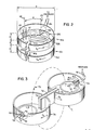
- one type of NMR local coil suitable for use in the present invention includes a pair of loop-gap resonators 50 and 5l.
- Each resonator 50 and 5l is comprised of a loop of conductive material 52 which serves as an inductive element and a gap 53 formed by parallel plates of conductive material which serves as a capacitive element.
- Details of loop-gap resonator geometry are generally known in the art and also described in U.S. Patent No. 4,446,429, the contents of which are herein incorporated by reference.
- the two loop-gap resonators 50 and 5l are aligned axially and separated by a distance d.
- the resulting local coil is characterized by Counter Rotating Currents (CRC), namely I3 and I4, in the loops 52 of the respective loop-gap resonators.
- CRC Counter Rotating Currents
- Such a configuration is designated herein as a CRC pair.
- the width of the conductive loops 52 is Z and the diameter of the loops 52 is D.
- the values D, d, and Z can vary significantly to produce local coils of different diameters, D, ranging from about 5 cm to about l5 cm by changing d and Z proportionately.
- the conductive loops 52 are formed on the inside surface of a section of polyvinylchloride (PVC) tubing (not shown) having an appropriate inside diameter using adhesive backed copper foil type no. ll5l manufactured by 3M company.
- the gaps 53 are formed from double-sided printed circuit board material, which is commercially available.
- the printed circuit board material is bonded edgewise on the inside of the PVC tubing to form the capacitive element of each loop-gap resonator 50 and 5l.
- the copper foil on each side of the circuit board serves as a plate of the capacitive element and is bonded to one end of the respective conductive loops 52.
- the printed circuit board material is trimmed in size to tune the CRC mode of the local coil to the resonant frequency of the gyromagnetic material of interest (near 64 MHz in the scanner of Fig. lA).
- a pair of crossed wires 54 are used to connect opposite plates of the capacitive elements of the resonators 50 and 5l.
- a coupling structure 55 is employed to couple the NMR signal from the loop-gap resonators 50 and 5l to a transmission line 56.
- the coupling structure 55 is formed from a folded loop of solid copper wire.
- the folded loop structure consists of an upper portion and a lower portion which are parallel to each other. Like the CRC pair, the folded loop structure itself possesses the property of intrinsic isolation. A uniform field of arbitrary polarization does not interact with the coupling structure 55.
- the currents in the upper and lower portions of the coupling structure 55 are opposite in direction, thus permitting coupling to the CRC mode of the resonators 50 and 5l when the coupler lies midway between the loops 52.
- Other types of coupling structures may also be used with this invention.
- the NMR signal may be taken directly from one of the gaps 53 by connecting a pair of lead wires.
- the coupling structure 55 is mounted between the loops 52 at a position indicated by dashed line 57 which is directly across from the gaps 53. Because it lies midway between the plates of the capacitor, the line 57 represents the position of zero voltage between the loops 52. By mounting the coupling structure 55 at the zero potential line 57, voltage insulation problems are reduced.
- the coupling structure 55 is bonded to a standard BNC connector 58, well-known in the art, for connection through the transmission line 56 to a receiver (not shown). The receiver amplifies, detects, and processes the NMR signals in well-known fashion.
- a pair of diodes 60 and 6l are connected across the loops 52 to provide passive decoupling during excitation.
- the diodes 60 and 6l are of the fast recovery type, suitable for use at VHF frequencies.
- the diodes 60 and 6l are connected back-to-back with the cathode of diode 60 and the anode of diode 6l being connected to resonator 50, while the anode of diode 60 and the cathode of diode 6l are connected to resonator 5l.
- the diodes 60 and 6l are connected to the loops 52 next to each other at a position indicated by dashed line 62.
- the angle ⁇ between the respective axes 57 and 62 is chosen such that the voltage between the loops 52 at this point causes the diodes 60 and 6l to conduct and thereby de-tune the NMR coil when large, nonhomogeneous electromagnetic fields are applied.
- the angle ⁇ is forty-five degrees.
- the CRC NMR coil of Fig. 2 is said to be "intrinsically isolated" in that a signal will not be produced in the cable 56 as a result of a homogeneous magnetic field which passes through both loop-gap resonators 50 and 5l.
- a magnetic field produced by gyromagnetic material located near the top or bottom of the CRC NMR coil is not homogeneous, and it will produce an NMR signal in the cable 56.
- the planar pair includes two loop-gap resonators 70 and 7l arranged side-by-side in what is termed herein as a planar pair configuration.
- a gap 72 common to both resonators 70 and 7l is formed by plates 73 and 74 which function as the capacitive elements and also connect the resonators 70 and 7l together.
- the planar pair is constructed in a manner similar to that described above for the CRC pair, using adhesive-backed copper foil inside PVC tubing for the loops and double-sided printed circuit board material for the capacitive elements.
- the loop-gap resonators 70 and 7l may be constructed with a wide variety of dimensions with the main diameter of each loop-gap resonator 70 and 7l typically from 5 to l5 cm. Because the plates 73 and 74 are common to both resonators, the currents I5 and I6 are forced to be in opposite directions. As a result, the paths for magnetic flux through the resonators 70 and 7l as indicated by dashed line 75 is also in opposite directions through the resonators 70 and 7l. Therefore, the planar pair also possesses the property of intrinsic isolation as it does not couple to a uniform magnetic field.
- passive decoupling for the planar pair is accomplished using conductive loops 76 and 77 in the interior of each resonator 70 and 7l.
- Each conductive loop is approximately one-half of the main diameter of the loop-gap resonators 70 and 7l.
- One of the conductive loops 76 functions as a pick-up loop to couple the received NMR signal through a coaxial connector 80 to a coaxial cable 8l.
- the other end of the coaxial cable 8l connects to a receiver (not shown), where the NMR signal is detected and processed in well-known fashion.
- One end 82 of the pick-up loop 76 is attached onto the outer rim 83 of the coaxial connector 80, while the other end 84 of the pick-up loop 76 is attached to the center terminal (not shown) of the coaxial connector 80.
- the connection of the two ends 82 and 84 of the pick-up loop 76 to the coaxial connector 80 provides both physical support for the pick-up loop 76 and electrical isolation for the two ends 82 and 84.
- the pick-up loop contains an open segment shown generally at 85 across the ends 82 and 84.
- a pair of back-to-back diodes 86 and 87 are connected across the open segment 85.
- the second conductive loop 77 is used for this purpose, acting only as a dummy loop to provide symmetry for the pick-up loop 76.
- the dummy loop 77 has two ends 90 and 9l which are anchored into the PVC tubing which forms an insulating wall of loop-gap resonator 70 and are insulated from the copper foil on the inside of the insulating wall.
- the dummy loop 77 therefore contains an open segment shown generally at 92 across the ends 90 and 9l.
- Another pair of back-to-back diodes 94 and 95 are connected across the open segment 92.
- the diodes 86-87 and 94-95 are also fast recovery type suitable for use at VHF frequencies.
- nonuniform components of the excitation field cause the voltage across the open segments 85 and 92 to rise until the threshold voltage of the back-to-back diodes 86-87 and 94-95 is reached. Then the diodes 86-87 and 94-95 begin conducting, thereby effectively changing the pick-up loop 76 and the dummy loop 77 into shorted turns. This results in a sharp lowering of the Q and shifting of the resonant frequency of the planar pair, thereby decoupling it from the excitation field. After the excitation field is removed to receive the NMR signals, the diodes 86-87 and 94-95 revert to their nonconducting state and are effectively out of the circuit. The NMR signal is then coupled by the pick-up loop 76 into the coaxial cable 8l.
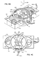
- Fig. 4A where a planar pair l00 and a CRC pair l02 are shown positioned on a common plane indicated by dashed line l06.
- the "vector reception field" of the planar pair l00 is illustrated by dashed lines l0l, and the vector reception field of the CRC pair l02 is illustrated by dashed lines l03.
- the vector reception field In the region of interest of the planar pair l00, the vector reception field has a direction indicated by arrows l04, and in the region of interest of the CRC pair l02, the vector reception field has a direction indicated by the arrows l05.
- the respective NMR coils l00 and l02 are sensitive to orthogonal components of a magnetic field produced by NMR excitation.
- the two coils can be combined into a network to form a single NMR probe, designated herein as a quadrature probe, which is sensitive to both orthogonal components of an NMR signal.
- a quadrature probe which is sensitive to both orthogonal components of an NMR signal.
- This provides an improvement in the signal- to-noise ratio by a factor of ⁇ 2 for the quadrature probe as compared to a single local coil.
- the mutual inductance between the planar pair and CRC coil is minimal when they are aligned with a common plane of symmetry. This enables networks of NMR local coils to be constructed to substantially increase the field of view without losing the signal-to-noise advantages characteristic of local coils.
- NMR probe includes a planar pair local coil ll0 sandwiched between the loops of a CRC pair local coil lll.
- the planar pair local coil ll0 is formed from a block ll2 of polymethylmethacrylate material, which is commercially available.
- Two cylindrical cut-outs ll3 and ll4 in the block ll2 define the loops of the planar pair.
- the actual loops ll5 and ll6 are formed by adhesive-backed copper foil on the inside of each cylindrical cut-out ll3 and ll4 respectively.
- a channel is also cut into the block ll2 connecting the two cylindrical cut-outs ll3 and ll4 which defines the common gap for the planar pair ll0.
- the actual gap if formed by a piece of double-sided microwave type printed circuit board material ll7 inserted in the channel.
- the printed circuit board material ll7 also serves to connect the gaps of the two loops ll5 and ll6 in parallel.
- the resonant frequency of the planar pair ll0 may be adjusted by trimming the ends of the printed circuit board ll7 or by adding a trimming capacitor (not shown) across the common gap.
- a pick-up loop ll8 and dummy loop ll9 with back-to-back diode pairs l20 and l2l respectively are used to provide passive decoupling as described above.
- a cable l22 couples the signal from the pick-up loop ll8 to the preamplifier.
- the CRC pair lll is formed from a piece of PVC tubing in which the area between the loops of the CRC pair is cut away to allow the planar pair ll0 to be disposed there. Otherwise, the construction of the CRC pair ll2 is similar to that described above in relation to Fig. 2. Adhesive-backed copper foil is used to form the loops l23 and a piece of microwave type printed circuit board material l24 is used for each of the gaps. Although only the upper loop is visable in Figs. 4B and 4C, the lower loop is identical. A pair of crossed wires l25 connect opposite plates of the upper and lower gap together.
- a folded loop coupling structure l26 is used to couple the NMR signal from the loops l23 to a cable l27 for connection to a preamplifier.
- the folded loops of the coupling structure l26 are extended above and below the block ll2 to provide the necessary clearance.
- Two pairs of back-to-back diodes l28 and l29 are used to provide passive decoupling as described above.
- the diode pairs l28 and l29 are each positioned 20 degrees on either side of the coupling structure l26.
- the approximate dimensions are as follows.
- the loops l23 of the CRC pair are 7.5 cm in diameter and .6 cm in width.
- the block ll2 which forms the planar pair ll0 is l.9 cm thick by l0 cm wide by l7 cm long. These dimensions are used for simplicity of construction and are not critical to the function of the quadrature probe.
- a wide range of dimensions for the quadrature probe, and relative dimensions for the local coils within the quadrature probe are possible, provided that the local coils are arranged to maintain symmetry and thereby minimize mutual inductance.
- the receiver and phase detector 37 includes separate pre-amplifiers l70 and l7l for inputs from the planar pair ll0 and CRC pair lll through the cables l22 and l27 respectively. Since these signals are orthogonal, they may be combined in a 90 degree hybrid combiner l72.
- the hybrid combiner l72 used in this embodiment is a type QHC-3-60 manufactured by Merricac of West Caldwell, New Jersey.
- the output l73 of the hybrid combiner l72 is then processed by the customary single channel detector and filter l74, and then output to the Analog to Digital (A/D) converter 39.
- A/D Analog to Digital
- the signals could be processed in parallel by a second detector, filter, and A/D converter (not shown) and then combined in the processor 35.
- a coordinate system l30 indicates reference directions for the discussion below.
- the geometric centers of the planar pair and CRC pair coincide. It is an important teaching of this invention that local coils, which are isolated from each other by virtue of orthogonal vector reception fields, may also be displaced from one another and still maintain their isolation. Fields arising from currents in either loop ll5 or ll6 of the planar pair ll0 couple to both loops l23 of the CRC pair lll which generates emf's in the loops l23 which are canceled by the crossed wires l25 across the gaps. This type of cancellation is termed herein as "emf cancellation".
- a second type of cancellation occurs because the fields arising from currents in loops ll5 and ll6 of the planar pair ll0 are equal and opposite as they pass through either loop l23 of the CRC pair lll and the fields therefore cancel.
- the CRC pair lll is translated in the x-z plane, emf cancellation is still effective and isolation between the local coils is preserved.
- the CRC pair lll is translated along the z axis, both emf and field cancellation remain in effect and the local coils remain isolated.
- the CRC pair lll may be both translated in the y-z plane and rotated about the x axis with field cancellation still in effect providing isolation for the local coils.
- the quadrature probe described above is one example of such a network in which the regions of sensitivity of the two coils coincide, resulting in an increase in the signal-to-noise ratio. If the local coils are displaced from one another, the net region of sensitivity is expanded so that a larger area can be examined in a given time, but without the same increase in signal-to-noise ratio.
- a second embodiment of the invention includes a network of local coils aligned on an axis l40 comprising a planar pair l4l flanked on either side by CRC pairs l42 and l43.
- the planar pair l4l and either CRC pair l42 or l43 are isolated from each other as described above, In other words, each CRC pair l42 and l43 considered separately is isolated from the planar pair.
- the CRC pairs l42 and l43 are isolated from each other because they are separated enough so that their respective regions of sensitivity do not overlap. Referring to Fig.
- the regions of sensitivity l44 and l45 for the CRC pairs l42 and l43 respectively do not overlap with each other, but both regions of sensitivity of the CRC pairs l42 and l43 overlap a portion of the region of sensitivity l46 of the planar pair l4l.
- This expanded region of sensitivity may be utilized in several ways. The three separate signals may be sampled separately on successive examination cycles. While this technique takes more time, it can be implemented simply on existing systems without extensive modification, while still saving patient set-up time. On the other hand, since the signals from the three local coils are isolated, all three signals could be sampled during a single examination cycle and then either stored for subsequent processing or processed in parallel.
- a third embodiment of the invention includes a network of local coils comprising a CRC pair l50 flanked on either side by planar pairs l5l and l52.
- a network of local coils comprising a CRC pair l50 flanked on either side by planar pairs l5l and l52.
- either planar pair l5l or l52 is isolated from the CRC pair l50 and the planar pairs l5l and l52 are isolated from each other by their physical separation. Therefore, this network also provides a net region of sensitivity which spans all three local coils similar to the second embodiment described above.
- a fourth embodiment of the invention includes an isolated local coil indicated by block l60, flanked on both sides by single turn loop type local coils l6l and l62 as are commonly used in the art.
- the isolated local coil l60 may be a CRC pair, planar pair, butterfly pair, or other isolated geometry. In the case that the isolated local coil l60 is a CRC pair, isolation from the single turn local coil is achieved by emf cancellation. If the isolated local coil l60 is a planar pair of butterfly pair, then isolation is provided by field cancellation.
- a network of local coils is arranged in an alternating pattern of planar pair and CRC pair of local coils.
- sequential local coils lie in the y-z plane and are angled slightly about their x axis as described above in relation to Fig. 4B. This arrangement is particularly useful for examining a long, curved surface of a human patient such as, for example, the spine.
- a butterfly pair is described in EP Patent Application No. 86 l06 l99.2 filed on May 6, l986, the contents of which are herein incorporated by reference.
- the butterfly pair has construction and properties similar to the planar pair and may be used interchangeably with the planar pair in the second and third embodiments described above.
- Fig. 7 illustrates a butterfly pair being used in the second embodiment.
Abstract
Description
- The field of the invention is gyromagnetic resonance spectroscopy, and particularly, local coils which are used to receive the signals produced by gyromagnetic resonance systems.
- Gyromagnetic resonance spectroscopy is conducted to study nuclei that have magnetic moments and electrons which are in a paramagnetic state. The former is referred to in the art as Nuclear Magnetic Resonance (NMR), and the latter is referred to as Paramagnetic Resonance (EPR) or Electron Spin Resonance (ESR). There are other forms of gyromagnetic spectroscopy that are practiced less frequently, but are also included in the field of this invention.
- Any nucleus which possesses a magnetic moment attempts to align itself with the direction of the magnetic field in which it is located. In doing so, however, the nucleus processes around this direction at a characteristic angular frequency (Larmor frequency) which is dependent on the strength of the magnetic field and on the properties of the specific nuclear species (the magnetogyric constant of the nucleus).
- When a substance such as human tissue is subjected to a uniform magnetic field (polarizing field Bz), the individual magnetic moments of the paramagnetic nuclei in the tissue attempt to align with this field but precess about it in random order at their characteristic Larmor frequency. A net magnetic moment Mz is produced in the direction of the polarizing field, but the randomly oriented components in the perpendicular plane (x-y plane) cancel one another. If, however, the substance, or tissue, is irradiated with a magnetic field (excitation field B₁) which is in the x-y plane and which is near the Larmor frequency, the net aligned moment, Mz, can be rotated into the x-y plane to produce a net transverse magnetic moment M₁ which is rotating in the x-y plane at the Larmor frequency.
- The practical value of this gyromagnetic phenomena resides in the radio signal which is emitted after the excitation signal B₁ is terminated. When the excitation signal is removed, an oscillating sine wave referred to as an NMR signal is induced in a receiving coil by the rotating field produced by the transverse magnetic moment M₁. The frequency of this signal is the Larmor frequency, and its initial amplitude, A₀, is determined by the magnitude of M₁.
- The NMR systems which implement these techniques are constructed in a variety of sizes. Small, specially designed machines are employed to examine laboratory animals or to examine specific parts of the human body. On the other hand, "whole body" NMR scanners are sufficiently large to receive an entire human body and produce an image of any portion thereof. Whole body scanners may employ an excitation coil for producing the excitation field and a separate receiver coil for receiving the NMR signal. The excitation coil produces a highly uniform, or homogeneous, excitation field throughout the entire area of interest, whereas the receiver coil is placed near the immediate area of interest to receive the NMR signal. The receiver coil is sharply tuned to the Larmor frequency of the nuclei of interest.
- Recently, a novel resonator structure referred to in the art as a "loop-gap" resonator has been applied to the field of gyromagnetic resonance spectroscopy. As indicated in the U.S. Patent Nos. 4,435,680; 4,446,429; 4,480,239 and 4,504,577, the loop-gap resonator may take a wide variety of shapes. In all cases, however, a lumped circuit resonator is formed in which a conductive loop is the inductive element and one or more gaps are formed in this loop to form a capacitive element. While the loop-gap resonator has many desirable characteristics normally associated with lumped circuit resonators, it also has some characteristics normally associated with cavity resonators. Most notable of these is the much higher quality factor, or "Q", of the loop-gap resonator over the traditional lumped circuit resonators. When applied to NMR scanners, this higher Q provides a higher signal to noise ratio which translates into higher resolution images and shorter scan times.
- To enhance the signal to noise ratio (SNR) of the receiver coil, it is common practice to reduce its physical size and place it adjacent the immediate region of interest. Such receiver coils are referred to as "surface coils", or "local coils", because their reception field is limited in size to the local area. For example, in prior EP Patent Application No. 86 l06 l99.2 filed on May 6, l986, local coils specifically designed for producing images of the head and neck regions of a human subject are described. In general, the more nearly the reception field of the local coil matches the field of interest, the better the resulting NMR signal.
- The present invention relates to a network of local coils which are combined to shape the reception field of the resulting NMR probe and to increase the quality of the received NMR signals. More specifically, the present invention is an NMR probe comprised of a plurality of local coils which are physically shaped and positioned to provide the desired reception field, and in which the mutual inductance between the respective local coils is minimized by aligning them along a plane of symmetry and at least one of the local coils is intrinsically isolated. The NMR signals produced by the respective coils are separately processed and added together to provide a view of the entire field of interest.
- A general object of the invention is to provide an NMR probe which provides an NMR signal of improved quality. By combining a plurality of local coils, they can be sized, shaped and positioned to provide a reception field which comforms to the field of interest. For example, if the field of interest is the spinal column of a human subject, a series of local coils disposed in a line along the spine will provide the desired, localized reception field. Thus, the resulting NMR probe receives a signal only from the region of interest. In addition, it has been discovered that if the mutual inductance between respective local probes is minimized, the quality of the resulting signal from the NMR probe is enhanced further.
- Another general object of the invention is to reduce the time required to conduct an NMR scan of a region of interest. This is accomplished in two ways. First. because the quality of the signal produced by the present invention is a substantial improvement, that quality may be traded off in favor of a corresponding reduction in the NMR measurement cycle time. And second, the time needed to prepare a subject for scanning may be reduced by employing a plurality of local coils in a single session rather than using a single local coil at various positions in a succession of separate sessions.
- The foregoing and other objects and advantages of the invention will appear from the following description. In the description, reference is made to the accompanying drawings which form a part hereof, and in which there is shown by way of illustration a preferred embodiment of the invention. Such embodiment does not necessarily represent the full scope of the invention, however, and reference is made therefore to the claims herein for interpreting the scope of the invention.
-
- Fig. lA is a pictorial view of a whole body NMR scanner system which employs the present invention;
- Fig. lB is an electrical block diagram of the NMR scanner system of Fig. l;
- Fig. 2 is a perspective view of a local coil which may be employed as part of the present invention and which is referred to as a CRC pair;
- Fig. 3 is a perspective view of another local coil which may be employed as part of the present invention and which is referred to as a planar pair;
- Fig. 4A is a schematic representation of the vector reception fields of a CRC pair and a planar pair;
- Fig. 4B is a perspective view of a first preferred embodiment of the invention which is referred to herein as a quadrature probe;
- Fig. 4C is a top elevation view of the quadrature probe;
- Fig. 4D is a schematic diagram of the receiver and phase detector which forms a part of the scanner system of Fig. lB connected to the quadrature probe of Figs. 4B and 4C.
- Fig. 5A is a pictoral view of a second embodiment of the invented NMR probe;
- Fig. 5B is a pictoral view of a third embodiment of the invented NMR probe;
- Fig. 5C is a pictoral view of a fourth embodiment of the invented NMR probe;
- Fig. 5D is a schematic diagram of a fifth embodiment of the invented NMR probe; and
- Fig. 6 is a graphic representation of the reception field of the NMR probe of Fig. 5A; and
- Fig. 7 is a pictoral view of the embodiment of Fig. 5A using a butterfly pair local coil.
- Although the present invention may be easily implemented in a variety of NMR scanner or NMR spectrometer structures, the preferred embodiments of the invention have been employed to detect the NMR signals produced in a large, whole-body NMR scanner. Referring particularly to Fig. lA, this scanner employs a
polarizing magnet 20 which is comprised of four circular cylindrical segments 2l-24 of sufficient size to receive a table 25. A patient may be placed on the table 25 and any portion of his body may be scanned by suitably positioning him with respect to a set of excitation coils 26. Thepolarizing magnet 20 produces a strong magnetic field Bz which is constant and homogeneous within the space defined by the excitation coils 26. The excitation coils 26 produce an excitation field B₁ which is in the transverse plane, perpendicular to the polarizing field Bz. The excitation field B₁ oscillates at a radio frequency ω0 = 63.89 MHz, and it is applied as one or more pulses during each measurement cycle. There are also three sets of gradient coils 27-29 (not shown in Fig. lA) which produce magnetic field gradients in the region between the excitation coils 26. - Referring particularly to Fig. lB, the control system for the NMR scanner includes a set of four static power converters 30-33 which connect to an a.c.
power source 34. The static converters 30-33 produce d.c. currents for therespective coils 20 and 27-29 at levels determined by commands received from a processor 35. Both the magnitude and the direction of the gradient fields in the x, y and z directions are controlled by the processor 35 to "scan" a region between the excitation coils 26 and to thereby collect spacially encoded NMR data which can be reconstructed into an image. - The processor 35 also controls the operation of an excitation field oscillator 36 which is connected to the excitation coils 26 and which is turned on and off during each measurement cycle of the scanning process. The oscillator 36 also provides a reference signal to a receiver and
phase detector circuit 37, which in turn is connected to receive the NMR signals from alocal NMR probe 38. The NMR signals are amplified and detected by thecircuit 37 and are then applied to the input of an analog-to-digital converter 39. The digitized NMR signals are processed using well-known NMR imaging techniques, and image data is produced by the processor 35 for display on a CRT 40. - The present invention concerns the construction of the
local NMR probe 38, and as suggested in Fig. lB, this probe includes a plurality of local coils which are indicated at 4l and 42. Eachcoil 4l and 42 produces a separate NMR signal which is processed by the receiver/detector 37, analog todigital converter 39 and the data processor 35. This processing can be performed by providing separate channels for each NMR signal, or the separate NMR signals may be multiplexed through a single channel. By providing separate channels, the signals are processed in parallel and combined in the data processor 35 to produce the desired image. While separate NMR signals may be combined and applied to a single channel, it has been found that best results are achieved if at least a separate pre-amplifier is provided for each NMR local coil in theprobe 38. - The NMR probes described herein employ local NMR coils which have some very unique characteristics. Two such structures are shown in Figs. 2 and 3 and will now be described briefly. For a more complete description of the construction and theory of operation of these local NMR coils, reference is made to prior EP Patent Application No. 86 l06 l99.2, filed on May 6, l986.
- Referring to Fig. 2, one type of NMR local coil suitable for use in the present invention includes a pair of loop-
gap resonators 50 and 5l. Eachresonator 50 and 5l is comprised of a loop ofconductive material 52 which serves as an inductive element and agap 53 formed by parallel plates of conductive material which serves as a capacitive element. Details of loop-gap resonator geometry are generally known in the art and also described in U.S. Patent No. 4,446,429, the contents of which are herein incorporated by reference. - The two loop-
gap resonators 50 and 5l are aligned axially and separated by a distance d. The resulting local coil is characterized by Counter Rotating Currents (CRC), namely I₃ and I₄, in theloops 52 of the respective loop-gap resonators. Such a configuration is designated herein as a CRC pair. The width of theconductive loops 52 is Z and the diameter of theloops 52 is D. The values D, d, and Z can vary significantly to produce local coils of different diameters, D, ranging from about 5 cm to about l5 cm by changing d and Z proportionately. - The
conductive loops 52 are formed on the inside surface of a section of polyvinylchloride (PVC) tubing (not shown) having an appropriate inside diameter using adhesive backed copper foil type no. ll5l manufactured by 3M company. Thegaps 53 are formed from double-sided printed circuit board material, which is commercially available. The printed circuit board material is bonded edgewise on the inside of the PVC tubing to form the capacitive element of each loop-gap resonator 50 and 5l. The copper foil on each side of the circuit board serves as a plate of the capacitive element and is bonded to one end of the respectiveconductive loops 52. The printed circuit board material is trimmed in size to tune the CRC mode of the local coil to the resonant frequency of the gyromagnetic material of interest (near 64 MHz in the scanner of Fig. lA). To force theresonators 50 and 5l into the CRC mode as described above, a pair of crossedwires 54 are used to connect opposite plates of the capacitive elements of theresonators 50 and 5l. - A
coupling structure 55 is employed to couple the NMR signal from the loop-gap resonators 50 and 5l to atransmission line 56. Thecoupling structure 55 is formed from a folded loop of solid copper wire. The folded loop structure consists of an upper portion and a lower portion which are parallel to each other. Like the CRC pair, the folded loop structure itself possesses the property of intrinsic isolation. A uniform field of arbitrary polarization does not interact with thecoupling structure 55. The currents in the upper and lower portions of thecoupling structure 55 are opposite in direction, thus permitting coupling to the CRC mode of theresonators 50 and 5l when the coupler lies midway between theloops 52. Other types of coupling structures may also be used with this invention. For example, the NMR signal may be taken directly from one of thegaps 53 by connecting a pair of lead wires. - The
coupling structure 55 is mounted between theloops 52 at a position indicated by dashedline 57 which is directly across from thegaps 53. Because it lies midway between the plates of the capacitor, theline 57 represents the position of zero voltage between theloops 52. By mounting thecoupling structure 55 at the zeropotential line 57, voltage insulation problems are reduced. Thecoupling structure 55 is bonded to astandard BNC connector 58, well-known in the art, for connection through thetransmission line 56 to a receiver (not shown). The receiver amplifies, detects, and processes the NMR signals in well-known fashion. - A pair of
diodes 60 and 6l are connected across theloops 52 to provide passive decoupling during excitation. Thediodes 60 and 6l are of the fast recovery type, suitable for use at VHF frequencies. Thediodes 60 and 6l are connected back-to-back with the cathode ofdiode 60 and the anode of diode 6l being connected toresonator 50, while the anode ofdiode 60 and the cathode of diode 6l are connected to resonator 5l. Thediodes 60 and 6l are connected to theloops 52 next to each other at a position indicated by dashed line 62. The angle ϑ between therespective axes 57 and 62 is chosen such that the voltage between theloops 52 at this point causes thediodes 60 and 6l to conduct and thereby de-tune the NMR coil when large, nonhomogeneous electromagnetic fields are applied. In the preferred embodiment shown, the angle ϑ is forty-five degrees. - The CRC NMR coil of Fig. 2 is said to be "intrinsically isolated" in that a signal will not be produced in the
cable 56 as a result of a homogeneous magnetic field which passes through both loop-gap resonators 50 and 5l. However, a magnetic field produced by gyromagnetic material located near the top or bottom of the CRC NMR coil is not homogeneous, and it will produce an NMR signal in thecable 56. Reference is made to the above cited prior EP Patent Application No. 86 l06 l99.2 for a more detailed explanation of the operation of the CRC NMR coil of Fig. 2. - Another intrinsically isolated NMR coil is shown in Fig. 3. This coil is also described in great detail in the above cited prior EP Patent Application, and it is referred to therein as a "planar pair". The planar pair includes two loop-gap resonators 70 and 7l arranged side-by-side in what is termed herein as a planar pair configuration. A
gap 72 common to both resonators 70 and 7l is formed byplates plates - Still referring to Fig. 3, passive decoupling for the planar pair is accomplished using
conductive loops conductive loops 76 functions as a pick-up loop to couple the received NMR signal through acoaxial connector 80 to a coaxial cable 8l. The other end of the coaxial cable 8l connects to a receiver (not shown), where the NMR signal is detected and processed in well-known fashion. Oneend 82 of the pick-uploop 76 is attached onto theouter rim 83 of thecoaxial connector 80, while theother end 84 of the pick-uploop 76 is attached to the center terminal (not shown) of thecoaxial connector 80. The connection of the two ends 82 and 84 of the pick-uploop 76 to thecoaxial connector 80 provides both physical support for the pick-uploop 76 and electrical isolation for the two ends 82 and 84. Thus, the pick-up loop contains an open segment shown generally at 85 across theends back diodes open segment 85. - In order to maintain the integrity of the intrinsic isolation in the planar pair, it is critical to maintain symmetry between the loop-gap resonators 70 and 7l. The second
conductive loop 77 is used for this purpose, acting only as a dummy loop to provide symmetry for the pick-uploop 76. Thedummy loop 77 has two ends 90 and 9l which are anchored into the PVC tubing which forms an insulating wall of loop-gap resonator 70 and are insulated from the copper foil on the inside of the insulating wall. Thedummy loop 77 therefore contains an open segment shown generally at 92 across theends 90 and 9l. Another pair of back-to-back diodes 94 and 95 are connected across theopen segment 92. The diodes 86-87 and 94-95 are also fast recovery type suitable for use at VHF frequencies. - During excitation, nonuniform components of the excitation field cause the voltage across the
open segments loop 76 and thedummy loop 77 into shorted turns. This results in a sharp lowering of the Q and shifting of the resonant frequency of the planar pair, thereby decoupling it from the excitation field. After the excitation field is removed to receive the NMR signals, the diodes 86-87 and 94-95 revert to their nonconducting state and are effectively out of the circuit. The NMR signal is then coupled by the pick-uploop 76 into the coaxial cable 8l. - An important discovery of this invention is that while both the CRC pair and the planar pair are sensitive to NMR signals which are produced in a region of interest adjacent their face, their sensitivities are substantially orthogonal. This is illustrated in Fig. 4A, where a planar pair l00 and a CRC pair l02 are shown positioned on a common plane indicated by dashed line l06. The "vector reception field" of the planar pair l00 is illustrated by dashed lines l0l, and the vector reception field of the CRC pair l02 is illustrated by dashed lines l03. In the region of interest of the planar pair l00, the vector reception field has a direction indicated by arrows l04, and in the region of interest of the CRC pair l02, the vector reception field has a direction indicated by the arrows l05. When oriented as shown, therefore, the respective NMR coils l00 and l02 are sensitive to orthogonal components of a magnetic field produced by NMR excitation.
- There are two benefits which flow from the orthogonal nature of these vector reception fields. First, the two coils can be combined into a network to form a single NMR probe, designated herein as a quadrature probe, which is sensitive to both orthogonal components of an NMR signal. This provides an improvement in the signal- to-noise ratio by a factor of √2 for the quadrature probe as compared to a single local coil. Secondly, the mutual inductance between the planar pair and CRC coil is minimal when they are aligned with a common plane of symmetry. This enables networks of NMR local coils to be constructed to substantially increase the field of view without losing the signal-to-noise advantages characteristic of local coils.
- The first of these benefits will now be described with respect to the first preferred embodiment of the invention shown in Figs. 4B and 4C, and the second benefit will then be described with respect to a number of embodiments shown in Figs. 5A-5D.
- Referring particularly to Figs. 4B and 4C, and NMR probe includes a planar pair local coil ll0 sandwiched between the loops of a CRC pair local coil lll. The planar pair local coil ll0 is formed from a block ll2 of polymethylmethacrylate material, which is commercially available. Two cylindrical cut-outs ll3 and ll4 in the block ll2 define the loops of the planar pair. The actual loops ll5 and ll6 are formed by adhesive-backed copper foil on the inside of each cylindrical cut-out ll3 and ll4 respectively. A channel is also cut into the block ll2 connecting the two cylindrical cut-outs ll3 and ll4 which defines the common gap for the planar pair ll0. The actual gap if formed by a piece of double-sided microwave type printed circuit board material ll7 inserted in the channel. The printed circuit board material ll7 also serves to connect the gaps of the two loops ll5 and ll6 in parallel. The resonant frequency of the planar pair ll0 may be adjusted by trimming the ends of the printed circuit board ll7 or by adding a trimming capacitor (not shown) across the common gap. A pick-up loop ll8 and dummy loop ll9 with back-to-back diode pairs l20 and l2l respectively are used to provide passive decoupling as described above. A cable l22 couples the signal from the pick-up loop ll8 to the preamplifier.
- Still referring to Figs. 4B and 4C, the CRC pair lll is formed from a piece of PVC tubing in which the area between the loops of the CRC pair is cut away to allow the planar pair ll0 to be disposed there. Otherwise, the construction of the CRC pair ll2 is similar to that described above in relation to Fig. 2. Adhesive-backed copper foil is used to form the loops l23 and a piece of microwave type printed circuit board material l24 is used for each of the gaps. Although only the upper loop is visable in Figs. 4B and 4C, the lower loop is identical. A pair of crossed wires l25 connect opposite plates of the upper and lower gap together. A folded loop coupling structure l26 is used to couple the NMR signal from the loops l23 to a cable l27 for connection to a preamplifier. The folded loops of the coupling structure l26 are extended above and below the block ll2 to provide the necessary clearance. Two pairs of back-to-back diodes l28 and l29 are used to provide passive decoupling as described above. The diode pairs l28 and l29 are each positioned 20 degrees on either side of the coupling structure l26.
- In the quadrature probe of Figs. 4B and 4C, the approximate dimensions are as follows. The loops l23 of the CRC pair are 7.5 cm in diameter and .6 cm in width. The block ll2 which forms the planar pair ll0 is l.9 cm thick by l0 cm wide by l7 cm long. These dimensions are used for simplicity of construction and are not critical to the function of the quadrature probe. A wide range of dimensions for the quadrature probe, and relative dimensions for the local coils within the quadrature probe are possible, provided that the local coils are arranged to maintain symmetry and thereby minimize mutual inductance.
- Referring to Figs. lB and 4D, in order to combine the signals from the quadrature probe of Figs, 4B and 4C, the receiver and
phase detector 37 includes separate pre-amplifiers l70 and l7l for inputs from the planar pair ll0 and CRC pair lll through the cables l22 and l27 respectively. Since these signals are orthogonal, they may be combined in a 90 degree hybrid combiner l72. The hybrid combiner l72 used in this embodiment is a type QHC-3-60 manufactured by Merricac of West Caldwell, New Jersey. The output l73 of the hybrid combiner l72 is then processed by the customary single channel detector and filter l74, and then output to the Analog to Digital (A/D)converter 39. As an alternative to combining the tow signals from the preamplifiers l70 and l7l, the signals could be processed in parallel by a second detector, filter, and A/D converter (not shown) and then combined in the processor 35. - Referring again to Fig. 4B, a coordinate system l30 indicates reference directions for the discussion below. In the quadrature probe described above, the geometric centers of the planar pair and CRC pair coincide. It is an important teaching of this invention that local coils, which are isolated from each other by virtue of orthogonal vector reception fields, may also be displaced from one another and still maintain their isolation. Fields arising from currents in either loop ll5 or ll6 of the planar pair ll0 couple to both loops l23 of the CRC pair lll which generates emf's in the loops l23 which are canceled by the crossed wires l25 across the gaps. This type of cancellation is termed herein as "emf cancellation". A second type of cancellation, termed herein as "field cancellation", occurs because the fields arising from currents in loops ll5 and ll6 of the planar pair ll0 are equal and opposite as they pass through either loop l23 of the CRC pair lll and the fields therefore cancel. If the CRC pair lll is translated in the x-z plane, emf cancellation is still effective and isolation between the local coils is preserved. If the CRC pair lll is translated along the z axis, both emf and field cancellation remain in effect and the local coils remain isolated. Finally, the CRC pair lll may be both translated in the y-z plane and rotated about the x axis with field cancellation still in effect providing isolation for the local coils.
- Since the local coils can be displaced from one another and still remain isolated, it is possible with the present invention to form a network of local coils. The quadrature probe described above is one example of such a network in which the regions of sensitivity of the two coils coincide, resulting in an increase in the signal-to-noise ratio. If the local coils are displaced from one another, the net region of sensitivity is expanded so that a larger area can be examined in a given time, but without the same increase in signal-to-noise ratio.
- Referring to Fig. 5A, a second embodiment of the invention includes a network of local coils aligned on an axis l40 comprising a planar pair l4l flanked on either side by CRC pairs l42 and l43. In this embodiment, the planar pair l4l and either CRC pair l42 or l43 are isolated from each other as described above, In other words, each CRC pair l42 and l43 considered separately is isolated from the planar pair. In addition, the CRC pairs l42 and l43 are isolated from each other because they are separated enough so that their respective regions of sensitivity do not overlap. Referring to Fig. 6, the regions of sensitivity l44 and l45 for the CRC pairs l42 and l43 respectively do not overlap with each other, but both regions of sensitivity of the CRC pairs l42 and l43 overlap a portion of the region of sensitivity l46 of the planar pair l4l. Hence, there exists a net region of sensitivity, indicated generally by dashed line l47 which spans all three local coils. This expanded region of sensitivity may be utilized in several ways. The three separate signals may be sampled separately on successive examination cycles. While this technique takes more time, it can be implemented simply on existing systems without extensive modification, while still saving patient set-up time. On the other hand, since the signals from the three local coils are isolated, all three signals could be sampled during a single examination cycle and then either stored for subsequent processing or processed in parallel.
- Referring to Fig. 5B, a third embodiment of the invention includes a network of local coils comprising a CRC pair l50 flanked on either side by planar pairs l5l and l52. Like the network of local coils described above in relation to Fig. 5A, either planar pair l5l or l52 is isolated from the CRC pair l50 and the planar pairs l5l and l52 are isolated from each other by their physical separation. Therefore, this network also provides a net region of sensitivity which spans all three local coils similar to the second embodiment described above.
- It is a further teaching of this invention that it is sufficient for a single local coil to provide isolation to adjacent local coils in the network.
- Referring to Fig. 5C, a fourth embodiment of the invention includes an isolated local coil indicated by block l60, flanked on both sides by single turn loop type local coils l6l and l62 as are commonly used in the art. The isolated local coil l60 may be a CRC pair, planar pair, butterfly pair, or other isolated geometry. In the case that the isolated local coil l60 is a CRC pair, isolation from the single turn local coil is achieved by emf cancellation. If the isolated local coil l60 is a planar pair of butterfly pair, then isolation is provided by field cancellation.
- Referring to Fig. 5D, the second and third embodiments described above can be combined to form a fifth embodiment of the invention in which a network of local coils is arranged in an alternating pattern of planar pair and CRC pair of local coils. In this embodiment, sequential local coils lie in the y-z plane and are angled slightly about their x axis as described above in relation to Fig. 4B. This arrangement is particularly useful for examining a long, curved surface of a human patient such as, for example, the spine.
- There are many types of local coil geometries which can be isolated according to the present invention. For example, a butterfly pair is described in EP Patent Application No. 86 l06 l99.2 filed on May 6, l986, the contents of which are herein incorporated by reference. The butterfly pair has construction and properties similar to the planar pair and may be used interchangeably with the planar pair in the second and third embodiments described above. Fig. 7 illustrates a butterfly pair being used in the second embodiment.
Claims (11)
a first local coil (111) having a first reception pattern which couples to magnetic fields of a first orientation; and
a second local coil (110) having a second reception pattern which couples to magnetic fields of a second orientation which is substantially orthogonal to the first orientation;
wherein the first and second reception patterns substantially coincide in spatial coverage and at least one of the first or second local coils is intrinsically isolated with respect to a uniform magnetic field.
a first local coil (142, 151; 161) having a first region of sensitivity;
a second local coil (141; 150; 160) which is an isolated local coil having a second region of sensitivity and which is disposed adjacent to the first local coil with at least a part of the second region of sensitivity overlapping the first region of sensitivity and in which mutual inductance to the first local coil is canceled by the isolated local coil.
Applications Claiming Priority (2)
| Application Number | Priority Date | Filing Date | Title |
|---|---|---|---|
| US897177 | 1986-08-15 | ||
| US06/897,177 US4721913A (en) | 1985-05-08 | 1986-08-15 | NMR local coil network |
Publications (3)
| Publication Number | Publication Date |
|---|---|
| EP0256520A2 true EP0256520A2 (en) | 1988-02-24 |
| EP0256520A3 EP0256520A3 (en) | 1988-07-20 |
| EP0256520B1 EP0256520B1 (en) | 1992-04-01 |
Family
ID=25407466
Family Applications (1)
| Application Number | Title | Priority Date | Filing Date |
|---|---|---|---|
| EP87111711A Expired EP0256520B1 (en) | 1986-08-15 | 1987-08-13 | Nmr local coil network |
Country Status (4)
| Country | Link |
|---|---|
| US (1) | US4721913A (en) |
| EP (1) | EP0256520B1 (en) |
| JP (1) | JPS63111846A (en) |
| DE (1) | DE3777909D1 (en) |
Cited By (5)
| Publication number | Priority date | Publication date | Assignee | Title |
|---|---|---|---|---|
| EP0335534A2 (en) * | 1988-03-31 | 1989-10-04 | The Regents Of The University Of California | Rapid MRI using multiple receivers producing multiply phase-encoded data derived from a single NMR response |
| GB2219861A (en) * | 1988-06-15 | 1989-12-20 | Nat Res Dev | Surface coil structures for nmr imaging and spectroscopy |
| US5144241A (en) * | 1989-08-16 | 1992-09-01 | Siemens Aktiengesellschaft | Circularly polarizing rf antenna for an mri apparatus having a c-magnet |
| EP0565178A1 (en) * | 1992-04-09 | 1993-10-13 | Koninklijke Philips Electronics N.V. | Quadrature coil system for use in a magnetic resonance apparatus |
| EP1298446A2 (en) * | 2001-10-01 | 2003-04-02 | Siemens Aktiengesellschaft | Method of treatment of magnetic resonance reception signals and corresponding reception device |
Families Citing this family (39)
| Publication number | Priority date | Publication date | Assignee | Title |
|---|---|---|---|---|
| US4866387A (en) * | 1985-05-08 | 1989-09-12 | Mcw Research Foundation, Inc. | NMR detector network |
| US4918388A (en) * | 1985-08-14 | 1990-04-17 | Picker International, Inc. | Quadrature surface coils for magnetic resonance imaging |
| NL8603005A (en) * | 1986-11-27 | 1988-06-16 | Philips Nv | MAGNETIC RESONANCE DEVICE WITH FLEXIBLE QUADRATURE RINSE SYSTEM. |
| EP0281787A1 (en) * | 1987-02-25 | 1988-09-14 | Siemens Aktiengesellschaft | Surface resonator for a nuclear spin resonance apparatus |
| JPH05166Y2 (en) * | 1987-02-28 | 1993-01-06 | ||
| US5024229A (en) * | 1987-11-16 | 1991-06-18 | The University Of Rochester | Resonators for magnetic resonance imaging |
| JPH01207044A (en) * | 1988-02-15 | 1989-08-21 | Yokogawa Medical Syst Ltd | Receiving device of nuclear magnetic resonance image diagnostic apparatus |
| US4926120A (en) * | 1988-12-27 | 1990-05-15 | United Technologies Corporation | In-line metallic debris particle detection system |
| US4973908A (en) * | 1989-06-23 | 1990-11-27 | General Electric Company | NMR probe with multiple isolated coplanar surface coils |
| US5208534A (en) * | 1989-08-09 | 1993-05-04 | Kabushiki Kaisha Toshiba | Magnetic resonance imaging system |
| US5201312A (en) * | 1989-12-18 | 1993-04-13 | General Electric Company | Antennae for high-resolution magnetic resonance imaging of the eye |
| DE4138690C2 (en) * | 1991-11-25 | 1994-08-11 | Siemens Ag | Circularly polarizing local antenna for a nuclear magnetic resonance device |
| US5296813A (en) * | 1992-03-05 | 1994-03-22 | Picker International, Inc. | Magnetic resonance scanner with improved packaging for circuitry within the magnetic field |
| US5491415A (en) * | 1992-03-05 | 1996-02-13 | Picker International, Inc. | Magnetic resonance scanner with improved packaging for circuitry within the magnetic field |
| US5256971A (en) * | 1992-05-18 | 1993-10-26 | Medical Advances, Inc. | Multiple loop coil with improved decoupling |
| US5361764A (en) * | 1993-07-09 | 1994-11-08 | Grumman Aerospace Corporation | Magnetic resonance imaging foot coil assembly |
| US5394087A (en) * | 1993-08-11 | 1995-02-28 | Picker International, Inc. | Multiple quadrature surface coil system for simultaneous imaging in magnetic resonance systems |
| US5610520A (en) * | 1994-02-24 | 1997-03-11 | Medrad Inc. | Automatic orthogonality adjustment device for a quadrature surface coil for magnetic resonance imaging or spectroscopy |
| US5492122A (en) * | 1994-04-15 | 1996-02-20 | Northrop Grumman Corporation | Magnetic resonance guided hyperthermia |
| US5500596A (en) * | 1994-04-28 | 1996-03-19 | Wisconsin Alumni Research Foundation | Local coil array for magnetic resonance imaging of the lower extremities |
| US5543711A (en) * | 1994-11-22 | 1996-08-06 | Picker International, Inc. | Multiple quadrature volume coils for magnetic resonance imaging |
| US5578925A (en) * | 1995-08-18 | 1996-11-26 | Picker International, Inc. | Vertical field quadrature phased array coil system |
| US6137291A (en) * | 1996-08-19 | 2000-10-24 | Oregon Health Sciences University | Telescoping coil array for magnetic resonance imaging of extremities |
| US5757189A (en) * | 1996-11-27 | 1998-05-26 | Picker International, Inc. | Arbitrary placement multimode coil system for MR imaging |
| US5898306A (en) * | 1997-04-09 | 1999-04-27 | Regents Of The University Of Minnesota | Single circuit ladder resonator quadrature surface RF coil |
| US6323648B1 (en) | 1997-11-26 | 2001-11-27 | Medrad, Inc. | Peripheral vascular array |
| JPH11253418A (en) | 1998-03-11 | 1999-09-21 | Toshiba Corp | Rf coil of magnetic resonance imaging device |
| DE19928452A1 (en) | 1999-06-23 | 2000-12-28 | Siemens Ag | Reception antenna system for magnetic resonance signal |
| CA2334929A1 (en) * | 2000-02-10 | 2001-08-10 | Jarod Matwiy | Quadrature rf field coil for use in magnetic resonance |
| US6836118B2 (en) | 2000-03-10 | 2004-12-28 | Mri Devices Corp. | Method and apparatus for NMR imaging |
| US6768303B1 (en) * | 2001-03-16 | 2004-07-27 | General Electric Company | Double-counter-rotational coil |
| US6798202B2 (en) | 2001-11-23 | 2004-09-28 | Koninklijke Philips Electronics N.V. | Planar radio frequency coil for open magnetic resonance imaging systems |
| DE10334170B3 (en) * | 2003-07-26 | 2005-06-02 | Physikalisch-Technische Bundesanstalt Braunschweig Und Berlin | Arrangement for generating high-frequency B1 fields in NMR with surface current antennas |
| JP4105646B2 (en) | 2004-03-02 | 2008-06-25 | 株式会社日立製作所 | Nuclear magnetic resonance apparatus |
| US7394253B2 (en) * | 2004-11-16 | 2008-07-01 | Kabushiki Kaisha Toshiba | Radio frequency coil assembly and magnetic resonance imaging apparatus |
| WO2006131863A1 (en) * | 2005-06-10 | 2006-12-14 | Koninklijke Philips Electronics, N.V. | Patient support with integrated spine coil |
| US8030926B2 (en) * | 2006-03-15 | 2011-10-04 | Albert Einstein College Of Medicine Of Yeshiva University | Surface coil arrays for simultaneous reception and transmission with a volume coil and uses thereof |
| CN104055517B (en) * | 2013-03-22 | 2019-04-26 | 深圳联影医疗科技有限公司 | A kind of MR imaging apparatus and magnetic resonance scanning method |
| DE102014202716B4 (en) * | 2014-02-14 | 2018-11-29 | Siemens Healthcare Gmbh | Improve local SAR behavior of MRI transmit coils by using orthogonal loop antennas |
Citations (5)
| Publication number | Priority date | Publication date | Assignee | Title |
|---|---|---|---|---|
| US3771055A (en) * | 1972-03-17 | 1973-11-06 | Varian Associates | Double nuclear magnetic resonance coil |
| EP0155978A1 (en) * | 1984-03-29 | 1985-10-02 | Oxford Research Systems Limited | Method of operating a nuclear magnetic resonance spectrometer |
| EP0170514A2 (en) * | 1984-07-31 | 1986-02-05 | Oxford Research Systems Limited | Method and apparatus for obtaining N.M.R. spectra and coils for use therein |
| EP0201084A2 (en) * | 1985-05-08 | 1986-11-12 | MCW Research Foundation, Inc. | A local probe for use in NMR imaging |
| EP0204104A2 (en) * | 1985-06-07 | 1986-12-10 | BRUKER Analytische Messtechnik GmbH | Resonator arrangement |
Family Cites Families (10)
| Publication number | Priority date | Publication date | Assignee | Title |
|---|---|---|---|---|
| NL7314269A (en) * | 1973-10-17 | 1975-04-21 | Philips Nv | MICROWAVE DEVICE EQUIPPED WITH A 1/2 LAMBDA RESONATOR. |
| GB2076542B (en) * | 1980-05-21 | 1984-02-15 | Emi Ltd | Nmr imaging apparatus |
| DE3131946A1 (en) * | 1981-08-12 | 1983-03-17 | Siemens AG, 1000 Berlin und 8000 München | "HIGH-FREQUENCY MAGNETIC SYSTEM IN A FACILITIES OF THE NUCLEAR SPIN RESONANCE TECHNOLOGY" |
| US4446429A (en) * | 1981-10-09 | 1984-05-01 | Medical College Of Wisconsin | Microwave resonator |
| US4435680A (en) * | 1981-10-09 | 1984-03-06 | Medical College Of Wisconsin | Microwave resonator structure |
| US4504788A (en) * | 1982-09-03 | 1985-03-12 | The Medical College Of Wisconsin, Inc. | Enclosed loop-gap resonator |
| US4480239A (en) * | 1983-02-07 | 1984-10-30 | The Medical College Of Wisconsin Inc. | Loop-gap resonator network |
| GB2159958B (en) * | 1984-05-25 | 1988-03-02 | Picker Int Ltd | Rf field generating and detecting arrangements |
| US4636730A (en) * | 1984-08-16 | 1987-01-13 | General Electric Company | NMR spectroscopy body probes with at least one surface coil |
| US4570137A (en) * | 1984-09-04 | 1986-02-11 | Motorola, Inc. | Lumped-mode resonator |
-
1986
- 1986-08-15 US US06/897,177 patent/US4721913A/en not_active Expired - Lifetime
-
1987
- 1987-08-13 DE DE8787111711T patent/DE3777909D1/en not_active Expired - Lifetime
- 1987-08-13 EP EP87111711A patent/EP0256520B1/en not_active Expired
- 1987-08-14 JP JP62201995A patent/JPS63111846A/en active Pending
Patent Citations (5)
| Publication number | Priority date | Publication date | Assignee | Title |
|---|---|---|---|---|
| US3771055A (en) * | 1972-03-17 | 1973-11-06 | Varian Associates | Double nuclear magnetic resonance coil |
| EP0155978A1 (en) * | 1984-03-29 | 1985-10-02 | Oxford Research Systems Limited | Method of operating a nuclear magnetic resonance spectrometer |
| EP0170514A2 (en) * | 1984-07-31 | 1986-02-05 | Oxford Research Systems Limited | Method and apparatus for obtaining N.M.R. spectra and coils for use therein |
| EP0201084A2 (en) * | 1985-05-08 | 1986-11-12 | MCW Research Foundation, Inc. | A local probe for use in NMR imaging |
| EP0204104A2 (en) * | 1985-06-07 | 1986-12-10 | BRUKER Analytische Messtechnik GmbH | Resonator arrangement |
Non-Patent Citations (1)
| Title |
|---|
| MEDICAL PHYSICS, vol. 13, no. 1, January-February 1986, pages 1-7, New York, US; J.S. HYDE et al.: "Planar-pair local coils for high-resolution magnetic resonance imaging, particularly of the temporomandibular joint" * |
Cited By (11)
| Publication number | Priority date | Publication date | Assignee | Title |
|---|---|---|---|---|
| EP0335534A2 (en) * | 1988-03-31 | 1989-10-04 | The Regents Of The University Of California | Rapid MRI using multiple receivers producing multiply phase-encoded data derived from a single NMR response |
| EP0335534A3 (en) * | 1988-03-31 | 1991-02-27 | The Regents Of The University Of California | Rapid mri using multiple receivers producing multiply phase-encoded data derived from a single nmr response |
| GB2219861A (en) * | 1988-06-15 | 1989-12-20 | Nat Res Dev | Surface coil structures for nmr imaging and spectroscopy |
| US5143688A (en) * | 1988-06-15 | 1992-09-01 | National Research Development Corporation | Surface electrical coil structures |
| GB2219861B (en) * | 1988-06-15 | 1993-05-12 | Nat Res Dev | Improvements in or relating to surface electrical coil structures |
| US5144241A (en) * | 1989-08-16 | 1992-09-01 | Siemens Aktiengesellschaft | Circularly polarizing rf antenna for an mri apparatus having a c-magnet |
| EP0565178A1 (en) * | 1992-04-09 | 1993-10-13 | Koninklijke Philips Electronics N.V. | Quadrature coil system for use in a magnetic resonance apparatus |
| EP1298446A2 (en) * | 2001-10-01 | 2003-04-02 | Siemens Aktiengesellschaft | Method of treatment of magnetic resonance reception signals and corresponding reception device |
| EP1298446A3 (en) * | 2001-10-01 | 2003-04-09 | Siemens Aktiengesellschaft | Method of treatment of magnetic resonance reception signals and corresponding reception device |
| US6768302B2 (en) | 2001-10-01 | 2004-07-27 | Siemens Aktiengesellschaft | Magnetic resonance signal evaluation method and apparatus using combinations of simultaneously received antenna signals |
| CN1325925C (en) * | 2001-10-01 | 2007-07-11 | 西门子公司 | Signal analysis method for magnetic resonance signals and responsibel receiving device |
Also Published As
| Publication number | Publication date |
|---|---|
| EP0256520B1 (en) | 1992-04-01 |
| DE3777909D1 (en) | 1992-05-07 |
| US4721913A (en) | 1988-01-26 |
| EP0256520A3 (en) | 1988-07-20 |
| JPS63111846A (en) | 1988-05-17 |
Similar Documents
| Publication | Publication Date | Title |
|---|---|---|
| EP0256520B1 (en) | Nmr local coil network | |
| US5578925A (en) | Vertical field quadrature phased array coil system | |
| US4680549A (en) | NMR coil arrangement | |
| US6396271B1 (en) | Tunable birdcage transmitter coil | |
| US5898306A (en) | Single circuit ladder resonator quadrature surface RF coil | |
| US5682098A (en) | Open quadrature whole volume imaging NMR surface coil array including three figure-8 shaped surface coils | |
| US6847210B1 (en) | MRI antenna | |
| US5198768A (en) | Quadrature surface coil array | |
| US5664568A (en) | Split-top, neck and head vascular array for magnetic resonance imaging | |
| US7091721B2 (en) | Phased array local coil for MRI imaging having non-overlapping regions of sensitivity | |
| US4724389A (en) | Loop-gap resonator for localized NMR imaging | |
| US5757189A (en) | Arbitrary placement multimode coil system for MR imaging | |
| US5430378A (en) | NMR quadrature detection array | |
| US6008649A (en) | RF coil apparatus for MR system with lateral B0 field | |
| US5680047A (en) | Multipl-tuned radio frequency coil for simultaneous magnetic resonance imaging and spectroscopy | |
| EP0580327B1 (en) | Magnetic resonance apparatus | |
| EP0758092A1 (en) | Quadrature radio frequency coil for magnetic resonance imaging | |
| US4725779A (en) | NMR local coil with improved decoupling | |
| US20060033497A1 (en) | Degenerate birdcage coil and transmit/receive apparatus and method for same | |
| US20050062472A1 (en) | Mri tunable antenna and system | |
| US6404199B1 (en) | Quadrature RF coil for vertical field MRI systems | |
| US5689189A (en) | Technique for designing distributed radio frequency coils and distributed radio frequency coils designed thereby | |
| US5500596A (en) | Local coil array for magnetic resonance imaging of the lower extremities | |
| US7479784B2 (en) | Arrangements, systems and methods for facilitating and collecting information associated with fluxes of magnetic fields provided at various angles from one another | |
| US4866387A (en) | NMR detector network |
Legal Events
| Date | Code | Title | Description |
|---|---|---|---|
| PUAI | Public reference made under article 153(3) epc to a published international application that has entered the european phase |
Free format text: ORIGINAL CODE: 0009012 |
|
| AK | Designated contracting states |
Kind code of ref document: A2 Designated state(s): BE DE FR GB IT NL |
|
| PUAL | Search report despatched |
Free format text: ORIGINAL CODE: 0009013 |
|
| AK | Designated contracting states |
Kind code of ref document: A3 Designated state(s): BE DE FR GB IT NL |
|
| 17P | Request for examination filed |
Effective date: 19881007 |
|
| 17Q | First examination report despatched |
Effective date: 19900907 |
|
| GRAA | (expected) grant |
Free format text: ORIGINAL CODE: 0009210 |
|
| AK | Designated contracting states |
Kind code of ref document: B1 Designated state(s): BE DE FR GB IT NL |
|
| REF | Corresponds to: |
Ref document number: 3777909 Country of ref document: DE Date of ref document: 19920507 |
|
| ITF | It: translation for a ep patent filed |
Owner name: BUGNION S.P.A. |
|
| ET | Fr: translation filed | ||
| ITTA | It: last paid annual fee | ||
| PLBE | No opposition filed within time limit |
Free format text: ORIGINAL CODE: 0009261 |
|
| STAA | Information on the status of an ep patent application or granted ep patent |
Free format text: STATUS: NO OPPOSITION FILED WITHIN TIME LIMIT |
|
| 26N | No opposition filed | ||
| REG | Reference to a national code |
Ref country code: GB Ref legal event code: IF02 |
|
| PGFP | Annual fee paid to national office [announced via postgrant information from national office to epo] |
Ref country code: NL Payment date: 20060821 Year of fee payment: 20 |
|
| PGFP | Annual fee paid to national office [announced via postgrant information from national office to epo] |
Ref country code: BE Payment date: 20060828 Year of fee payment: 20 |
|
| PGFP | Annual fee paid to national office [announced via postgrant information from national office to epo] |
Ref country code: GB Payment date: 20060830 Year of fee payment: 20 |
|
| PGFP | Annual fee paid to national office [announced via postgrant information from national office to epo] |
Ref country code: IT Payment date: 20060831 Year of fee payment: 20 Ref country code: DE Payment date: 20060831 Year of fee payment: 20 |
|
| REG | Reference to a national code |
Ref country code: GB Ref legal event code: PE20 |
|
| NLV7 | Nl: ceased due to reaching the maximum lifetime of a patent |
Effective date: 20070813 |
|
| PG25 | Lapsed in a contracting state [announced via postgrant information from national office to epo] |
Ref country code: GB Free format text: LAPSE BECAUSE OF EXPIRATION OF PROTECTION Effective date: 20070812 |
|
| BE20 | Be: patent expired |
Owner name: *MCW RESEARCH FOUNDATION INC. Effective date: 20070813 |
|
| PG25 | Lapsed in a contracting state [announced via postgrant information from national office to epo] |
Ref country code: NL Free format text: LAPSE BECAUSE OF EXPIRATION OF PROTECTION Effective date: 20070813 |
|
| PGFP | Annual fee paid to national office [announced via postgrant information from national office to epo] |
Ref country code: FR Payment date: 20060831 Year of fee payment: 20 |