EP0255374A2 - Telephone circuit for supplying ringing signals to a subscriber telephone line and for detecting the unhooked condition during ringing - Google Patents
Telephone circuit for supplying ringing signals to a subscriber telephone line and for detecting the unhooked condition during ringing Download PDFInfo
- Publication number
- EP0255374A2 EP0255374A2 EP87306728A EP87306728A EP0255374A2 EP 0255374 A2 EP0255374 A2 EP 0255374A2 EP 87306728 A EP87306728 A EP 87306728A EP 87306728 A EP87306728 A EP 87306728A EP 0255374 A2 EP0255374 A2 EP 0255374A2
- Authority
- EP
- European Patent Office
- Prior art keywords
- circuit means
- input terminal
- signal
- terminal
- gate
- Prior art date
- Legal status (The legal status is an assumption and is not a legal conclusion. Google has not performed a legal analysis and makes no representation as to the accuracy of the status listed.)
- Granted
Links
Images


Classifications
-
- H—ELECTRICITY
- H04—ELECTRIC COMMUNICATION TECHNIQUE
- H04M—TELEPHONIC COMMUNICATION
- H04M19/00—Current supply arrangements for telephone systems
- H04M19/02—Current supply arrangements for telephone systems providing ringing current or supervisory tones, e.g. dialling tone or busy tone
- H04M19/026—Arrangements for interrupting the ringing current
Definitions
- the present invention relates to telephone circuits for detecting the unhooked condition during ringing and for supplying ringing signals to the line, for instance arranged to be monolithically integrated and to form an interface between a subscriber telephone line and a subscriber line circuit under the control of exchange control components.
- a subscriber telephone set is generally connected to a telephone exchange by a line whose terminals are connected, in parallel, to both a speech circuit and a ringer.
- the speech circuit is in series with a switch which is closed when the set is unhooked; the ringer is in series with a capacitor to decouple it from direct current in the line.
- a telephone line is supplied by a direct voltage generator, in series with which there is connected an alternating voltage generator which forms the source of ringing signals when the exchange control components generate a control signal for the supply of these signals to the subscriber.
- the ringing signals have a wave shape of sinusoidal type and are supplied to the subscriber at a predetermined ringing rhythm by the exchange control components.
- the line is supplied with a succession of these signals which are spaced from one another by pauses between signals.
- the detection of the unhooked condition is obtained in modern telephone exchanges by circuit means of electronic type arranged to recognize the variations in the line current and to detect the possible presence of a direct current in the line due to unhooking of the set.
- Passage from a calling signal supply stage to a pause stage where no signals are supplied, or vice versa may cause instantaneous voltage and current variations on the line which make it difficult to detect unhooking of the set. These variations may also cause harmonics which may disturb the users of neighbouring lines.
- the causes of these voltage and current transients may be due to both the difference which normally exists between the value of the direct component supplied to the telephone line during the supply of a ringing signal and the component supplied during the pause between signals, either during the supply of or on the discontinuation of a sinusoidal ringing signal to the line at a moment when its voltage amplitude is not zero.
- the sinusoidal ringing signals generally have a frequency of between 16 and 66Hz, with actual voltage values (60, 80 V) which are fairly high with respect to those of normal telephone speech signals: if they are not immediately discontinued when the set is unhooked, they are converted by the subscriber speech circuit into high intensity acoustic signals which may damage the subscriber's hearing as well as the set itself.
- the circuit means arranged to detect variations in the line current during unhooking should be able to supply a very rapid response, making it possible immediately to interrupt the supply of ringing signals to the line when unhooking takes place.
- the circuit means arranged to recognize variations in the line current could, however, interpret a variation in the line current due to other factors, for example disturbances caused by other subscribers, as a direct current variation on the line following unhooking.
- the possible presence of a direct component on the line may, for example, be checked for a second time, which would confirm that the subscriber has actually unhooked the set, as disclosed in the Italian Patent Application No. 67252-A/80.
- a telephone ringing system may not be monolithically integrated.
- a telephone circuit which may be monolithically integrated, for supplying ringing signals and for detecting the unhooked condition during ringing, arranged to form an interface between the subscriber telephone line and the subscriber line circuit under the control of exchange control components, which keeps the features of accuracy and rapidity of operation of known circuits unchanged and drastically reduces the generation of disturbances on the line with respect to such known circuits.
- the telephone circuit shown in Figure 1 comprises a timing signal generating circuit means FC having an output terminal and an input terminal SDS for connection to exchange components arranged to generate a signal with a wave shape which is substantially of sinusoidal type having a frequency identical to the frequency of the sinusoidal ringing signals to be supplied to the line but whose amplitude is lower than the amplitude thereof.
- An enabling circuit means ASI has a first input terminal connected to the output terminal of the circuit means FC, a second input terminal RN for connection to the exchange control components arranged to generate control signals for the supply of ringing signals, and a third input terminal for connection to exchange control components designed to generate control signals which determine the ringing rhythm.
- the enabling circuit means ASI also has first and second output terminals and an inhibiting terminal.
- a circuit means IS for supplying ringing signals has an input terminal coupled to the exchange components which generate the continuous signal of sinusoidal type, an enabling terminal which is connected to the first output terminal of the enabling circuit means ASI, and an output terminal.
- a circuit RS for detecting the direct current present on the line has a first input terminal which is supplied with the line current or an "image" current of the line current, an enabling terminal connected to the second output terminal of the enabling circuit means ASI, and an output terminal.
- a circuit means GS for controlling the detection of the unhooked condition has a first input terminal connected to the output terminal of the circuit means FC, a second input terminal for connection to the exchange control components which generate the control signal for the supply of ringing signals, a third input terminal connected to the output terminal of the circuit RS, a first output terminal connected to the inhibiting terminal of the enabling circuit means ASI, and a second output terminal for connection to the exchange control components.
- a circuit means AL for supplying the telephone line has a first input terminal connected to the output terminal of the circuit means IS, an enabling terminal for connection to the exchange control components which generate control signals for the supply of the ringing signals, and first and second output terminals for connection to the two wires of a subscriber telephone line.
- the circuit means FC for generating a timing signal may comprise a "zero crossing detector" of a type known to persons skilled in the art.
- the input terminal is supplied from a generator forming part of the exchange with a signal having a wave shape of sinusoidal type with a limited amplitude (IV RMS ) and a frequency equal to the frequency of the ringing signals to be supplied to the line.
- the circuit means FC generates at its output a pulse each time the input signal crosses zero in a predetermined direction. These signals are used as timing or clock signals for the operation of the circuit.
- the enabling circuit means ASI generates at the first output terminal an enabling signal for the call signal supply circuit means IS when control signals from the exchange components are simultaneously supplied to the second and third input terminals.
- the enabling signal commences upon receipt of the first timing signal following the receipt of a control signal at the third input terminal, and continues until receipt of the first timing signal following the end of the control signal.
- the generation of the enabling signal may, however, be cancelled by an inhibiting signal supplied to the inhibiting terminal of the enabling circuit means ASI and generated by the circuit means GS controlling the detection of unhooktng of the set.
- the ringing signal supplying circuit. means IS is always enabled or disabled only when the sinusoidal signal, from which the ringing signals originate, crosses zero.
- the circuit enabling means ASI also generates, at the second output terminal, a signal which enables operation of the circuit RS for detecting direct current on the line.
- the detection of'hirect current in the line is, however, enabled only after a predetermined time interval, equal to a whole number of periods of the sinusoidal signal generated by the exchange control components, from the moment at which a signal to supply or a signal to discontinue the supply of ringing signals to the line is generated.
- the enabling circuit means ASI comprises a D type bistable multfvibrator or flip flop F1, having a data input terminal D1, a clock input terminal CK1, a clear terminal CL1, and an output terminal Q1, a D type bistable multivibrator or flip flop F2, having a data input terminal D2, a clock input terminal cK2, a presetting terminal PS2, and an output terminal Q2, and an "exclusive NOR" gate P1 having first and second input terminals and an output terminal.
- the clock input terminals of the two multivibrators F1 and F2 are connected together to form the first input terminal of the enabling circuit means.
- the data input terminal D1 of the multivibrator F1 forms the third input terminal of the enabling circuit means.
- the clear terminal CL1 of the multivibrator F1 forms the inhibiting terminal of the enabling circuit means.
- the presetting terminal PS2 of the multivibrator F2 forms the second input terminal of the enabling circuit means.
- the output terminal Q1 of the multivibrator F1 and the data input terminal D2 of the multivibrator F2 are connected to the first input terminal of the gate P1 to form the first output terminal of the enabling circuit means.
- the output terminal Q2 of the multivibrator F2 is connected to the second input terminal of the gate P1.
- the output terminal of the gate P1 forms the second output terminal of the enabling circuit means.
- the ringing signal supplying circuit means IS may be formed by a circuit known in the art as an "electronic switch".
- the circuit means IS is enabled by the signal generated at the first output terminal of the enabling circuit means ASI to begin to supply the line with the sinusoidal signal generated by the exchange components via the circuit means AL which amplifies this signal, only when the signal crosses zero. It is thus possible to satisfy the condition that there are never instantaneous voltage variations on the line due to the supply of ringing signals, or the discontinuation of these signals, at moments at which the instantaneous amplitude of the signals originating from the sinusoidal signal is not zero.
- the telephone line supplying circuit means AL comprises both circuits arranged to amplify the ringing signals from the circuit means IS and circuits arranged to supply the telephone line connected thereto.
- the circuit means AL supplies the telephone line with a predetermined constant direct voltage when the exchange control components supply, via the terminal RN, the control signal on which the ringing signals from the circuit means IS are superimposed.
- the circuit means RS for detecting direct current in the line may in contrast be formed by a circuit comprising a line current transducer and an integrator which integrates the current supplied by the transducer over one or more whole periods of the line voltage using arrangements which are known.
- a circuit is disclosed, for example, in the Italian patent application number 23832 A/83 in the name of the present applicants.
- the integrator detects the presence of direct current in the line at a level higher than a predetermined threshold
- the circuit When the integrator detects the presence of direct current in the line at a level higher than a predetermined threshold, the circuit generates a signal indicating the presence of direct current in the line, which condition may be caused by a possible unhooking of the set.
- the information that direct current is present in the line is, however, further processed by the circuit means GS for controlling the detection of the unhooked condition to prevent erroneous signalling when unhooking has not taken place.
- the circuit means GS for controlling the detection of the unhooked condition On receipt of the first timing signal following the information that direct current is present in the line, the circuit means GS for controlling the detection of the unhooked condition generates at its first output terminal a signal which inhibits the ringing signal supplying circuit means IS and the circuit means RS for detecting direct current in the line to be disabled.
- enabling of the circuit means RS for detecting direct current in the line RS by means of the signal generated at the second output terminal of the enabling circuit means ASI is reset after a time interval equal to a predetermined number of periods of the sinusoidal signal from which the ringing signals originate.
- the signal generated by the circuit means RS again causes the inhibition of the enabling circuit means ASI, and therefore also of the circuit means IS and AL, and a signal indicating that unhooking has taken place is generated at the second output terminal of the circuit means GS for controlling the detection of the unhooked condition and continues to be generated as long as direct current is present in the line and the exchange control components confirm the ringing condition.
- the enabling circuit means ASI therefore enables the circuit means IS to supply ringing signals to the line and the circuit means RS for the detection of direct current in the line is also enabled after a period of time equal to a predetermined number of periods of the sinusoidal ringing signal.
- the above description relates to the operation of a telephone circuit in the case in which the presence of a direct current component in the line is detected during the supply of a ringing signal.
- the circuit means GS for controlling the detection of the unhooked condition also generates at the first output terminal an inhibiting signal which inhibits the circuit means ASI and therefore disables the supply of ringing signals to the line by the circuit means IS.
- the detection circuit means RS also remains disabled for a predetermined period of time equal to a certain number of periods of the sinusoidal ringing signal, from the moment at which the inhibiting signa! is generated for the enabling circuit ASI, following which it is again checked, on the following timing signal, whether the previously detected direct current component is still present in the line. If this is the case, the circuit means GS again generates an inhibiting signal for the enabling circuit means ASI and generates at the second output terminal a signal indicating that unhooking has taken place for the exchange components.
- the circuit means GS controlling the detection of the unhooked condition may be formed by a logic circuit of the type shown in Figure 3 and comprising an inverter G1 having an input terminal and an output terminal, six NAND gates G2, G3, G4, G5, G6, G7 each having first and second input terminals and an output terminal, and a NAND gate G8 having first, second and third input terminals and an output terminal.
- the circuit means GS also comprises two D type bistable multivibrators or D-type flip-flops F3 and F4, each having a data input terminal D3, D4, a clock input terminal CK3, CK4, a clear terminal CL3, CL4, and two output terminals Q3, Q3 and Q4, Q 4, respectively.
- the clock input terminals of the two multibrators F3 and F4 are connected together to form the first input terminal of the circuit means GS for controlling the detection of the unhooked condition.
- the input terminal of the gate G1 and the first input terminal of the gate G8 are connected together to form the second input terminal of the circuit means GS.
- the first input terminal of the gates G2 and G5 are connected together to form the third input terminal of the circuit means GS.
- the output terminal of the gate G7 forms the first output terminal of the circuit means GS.
- the output terminal of the gate G8 forms the second output terminal of the circuit means GS.
- the clear terminals CL3 and CL4 of the two multivibrators F3 and F4 are both connected to the output terminal of the gate G1.
- the second input terminal of the gate G2 is connected to the first input terminal of the gate G7 and to the first output terminal Q3 of the multivibrator F3.
- the output terminal of the gate G2 is connected to the first input terminal of the gate G4.
- the output terminal of the gate G3 is connected to the second input terminal of the gate G4 and to the first input terminal of the gate G6.
- the output terminal of the gate G4 is connected to the data input terminal D3 of the multivibrator F3.
- the first input terminal of the gate G3 is connected to the first output terminal Q4 of the multivibrator F4.
- the second input terminal of the gate G3, the second input terminal of the gate G5, and the second input terminal of the gate G8 are connected to the second output terminal Q3 of the multivibrator F3.
- the output terminal of the gate G5 is connected to the second input terminal of the gate G6.
- the output terminal of the gate G6 is connected to the data input terminal D4 of the multivibrator F4.
- the second output terminal Q4 of the multivibrator F4 is connected to the second input terminal of the gate, G7 and to the third input terminal of the gate G8.
- the telephone circuit thus enables the supply of a ringing signal to the line or the discontinuation thereof when the instantaneous amplitude of the ringing signal is zero, thereby eliminating instantaneous voltage and current variations on the line which might make it difficult to detect unhooking in very short periods and which could generate harmonics such as to disturb the users of neighbouring lines. It also enables the value of the direct voltage component supplied to the telephone line to be kept constant both during the supply of a ringing signal and during a pause between ringing signals.
- the detection of the presence of direct current in the line causes the cessation of the supply at the first moment at which the instantaneous amplitude of the signal is zero, thereby satisfying the requirement of rapid interruption of the supply of the ringing signal as soon as the presence of direct current in the line is detected so as not to damage the subscriber's hearing or telephone set.
- the presence of a direct component in the line is checked a second time, after a predetermined interval when no signals are being supplied to the line, to supply the exchange components reliably with correct information that the set has been unhooked.
Abstract
Description
- The present invention relates to telephone circuits for detecting the unhooked condition during ringing and for supplying ringing signals to the line, for instance arranged to be monolithically integrated and to form an interface between a subscriber telephone line and a subscriber line circuit under the control of exchange control components.
- A subscriber telephone set is generally connected to a telephone exchange by a line whose terminals are connected, in parallel, to both a speech circuit and a ringer. The speech circuit is in series with a switch which is closed when the set is unhooked; the ringer is in series with a capacitor to decouple it from direct current in the line.
- A telephone line is supplied by a direct voltage generator, in series with which there is connected an alternating voltage generator which forms the source of ringing signals when the exchange control components generate a control signal for the supply of these signals to the subscriber. The ringing signals have a wave shape of sinusoidal type and are supplied to the subscriber at a predetermined ringing rhythm by the exchange control components. Upon command by these components, the line is supplied with a succession of these signals which are spaced from one another by pauses between signals. When the ringing signals are supplied to the subscriber, there is therefore present in the line an alternating ringing current on which a direct current component is superimposed only when the set has been unhooked.
- When no ringing signal is supplied to the subscriber, or during the pauses between the signals, only a direct current component is present in the line when the set has been unhooked.
- The detection of the unhooked condition is obtained in modern telephone exchanges by circuit means of electronic type arranged to recognize the variations in the line current and to detect the possible presence of a direct current in the line due to unhooking of the set.
- Passage from a calling signal supply stage to a pause stage where no signals are supplied, or vice versa, may cause instantaneous voltage and current variations on the line which make it difficult to detect unhooking of the set. These variations may also cause harmonics which may disturb the users of neighbouring lines. The causes of these voltage and current transients may be due to both the difference which normally exists between the value of the direct component supplied to the telephone line during the supply of a ringing signal and the component supplied during the pause between signals, either during the supply of or on the discontinuation of a sinusoidal ringing signal to the line at a moment when its voltage amplitude is not zero.
- The sinusoidal ringing signals generally have a frequency of between 16 and 66Hz, with actual voltage values (60, 80 V) which are fairly high with respect to those of normal telephone speech signals: if they are not immediately discontinued when the set is unhooked, they are converted by the subscriber speech circuit into high intensity acoustic signals which may damage the subscriber's hearing as well as the set itself.
- To avoid this drawback, the circuit means arranged to detect variations in the line current during unhooking should be able to supply a very rapid response, making it possible immediately to interrupt the supply of ringing signals to the line when unhooking takes place. In certain circumstances, the circuit means arranged to recognize variations in the line current could, however, interpret a variation in the line current due to other factors, for example disturbances caused by other subscribers, as a direct current variation on the line following unhooking.
- To ensure that unhooking of the set has actually taken place, following the discontinuation of the supply of ringing signals, the possible presence of a direct component on the line may, for example, be checked for a second time, which would confirm that the subscriber has actually unhooked the set, as disclosed in the Italian Patent Application No. 67252-A/80. However, such a telephone ringing system may not be monolithically integrated.
- According to one aspect of the invention, there is provided a telephone circuit as defined in the appended Claim 1. According to another aspect of the invention, there is provided a telephone circuit as defined in the appended Claim 7. Preferred embodiments of the invention are defined in the other appended claims.
- It is thus possible to provide a telephone circuit, which may be monolithically integrated, for supplying ringing signals and for detecting the unhooked condition during ringing, arranged to form an interface between the subscriber telephone line and the subscriber line circuit under the control of exchange control components, which keeps the features of accuracy and rapidity of operation of known circuits unchanged and drastically reduces the generation of disturbances on the line with respect to such known circuits.
- The invention will be further described, by way of example, with reference to the accompanying drawings, in which :
- Figure 1 is a block diagram of a telephone circuit constituting a preferred embodiment of the invention, which is capable of being monolithically integrated, for the supply of ringing signals and the detection of the unhooked condition during ringing;
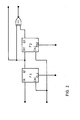
- Figure 2 is a circuit diagram of an enabling circuit means of the telephone circuit of Figure 1; and
- Figure 3 is a circuit diagram of a circuit means controlling the detection of the unhooked condition of the telephone circuit of Figure 1.
- The telephone circuit shown in Figure 1 comprises a timing signal generating circuit means FC having an output terminal and an input terminal SDS for connection to exchange components arranged to generate a signal with a wave shape which is substantially of sinusoidal type having a frequency identical to the frequency of the sinusoidal ringing signals to be supplied to the line but whose amplitude is lower than the amplitude thereof. An enabling circuit means ASI has a first input terminal connected to the output terminal of the circuit means FC, a second input terminal RN for connection to the exchange control components arranged to generate control signals for the supply of ringing signals, and a third input terminal for connection to exchange control components designed to generate control signals which determine the ringing rhythm. The enabling circuit means ASI also has first and second output terminals and an inhibiting terminal.
- A circuit means IS for supplying ringing signals has an input terminal coupled to the exchange components which generate the continuous signal of sinusoidal type, an enabling terminal which is connected to the first output terminal of the enabling circuit means ASI, and an output terminal. A circuit RS for detecting the direct current present on the line has a first input terminal which is supplied with the line current or an "image" current of the line current, an enabling terminal connected to the second output terminal of the enabling circuit means ASI, and an output terminal.
- A circuit means GS for controlling the detection of the unhooked condition has a first input terminal connected to the output terminal of the circuit means FC, a second input terminal for connection to the exchange control components which generate the control signal for the supply of ringing signals, a third input terminal connected to the output terminal of the circuit RS, a first output terminal connected to the inhibiting terminal of the enabling circuit means ASI, and a second output terminal for connection to the exchange control components.
- A circuit means AL for supplying the telephone line has a first input terminal connected to the output terminal of the circuit means IS, an enabling terminal for connection to the exchange control components which generate control signals for the supply of the ringing signals, and first and second output terminals for connection to the two wires of a subscriber telephone line.
- With the exception of the first and second output terminals of the circuit means AL, all the terminals of the various blocks of Figure 1 should be considered as usable for the transmission of both current and voltage signals.
- The circuit means FC for generating a timing signal may comprise a "zero crossing detector" of a type known to persons skilled in the art. The input terminal is supplied from a generator forming part of the exchange with a signal having a wave shape of sinusoidal type with a limited amplitude (IVRMS) and a frequency equal to the frequency of the ringing signals to be supplied to the line. The circuit means FC generates at its output a pulse each time the input signal crosses zero in a predetermined direction. These signals are used as timing or clock signals for the operation of the circuit.
- The enabling circuit means ASI generates at the first output terminal an enabling signal for the call signal supply circuit means IS when control signals from the exchange components are simultaneously supplied to the second and third input terminals. The enabling signal commences upon receipt of the first timing signal following the receipt of a control signal at the third input terminal, and continues until receipt of the first timing signal following the end of the control signal. The generation of the enabling signal may, however, be cancelled by an inhibiting signal supplied to the inhibiting terminal of the enabling circuit means ASI and generated by the circuit means GS controlling the detection of unhooktng of the set.
- To synchronize the timing signals and the sinusoidal input signal, the ringing signal supplying circuit. means IS is always enabled or disabled only when the sinusoidal signal, from which the ringing signals originate, crosses zero.
- The circuit enabling means ASI also generates, at the second output terminal, a signal which enables operation of the circuit RS for detecting direct current on the line.
- The detection of'hirect current in the line is, however, enabled only after a predetermined time interval, equal to a whole number of periods of the sinusoidal signal generated by the exchange control components, from the moment at which a signal to supply or a signal to discontinue the supply of ringing signals to the line is generated.
- As shown in Figure 2, the enabling circuit means ASI comprises a D type bistable multfvibrator or flip flop F1, having a data input terminal D1, a clock input terminal CK1, a clear terminal CL1, and an output terminal Q1, a D type bistable multivibrator or flip flop F2, having a data input terminal D2, a clock input terminal cK2, a presetting terminal PS2, and an output terminal Q2, and an "exclusive NOR" gate P1 having first and second input terminals and an output terminal.
- The clock input terminals of the two multivibrators F1 and F2 are connected together to form the first input terminal of the enabling circuit means. The data input terminal D1 of the multivibrator F1 forms the third input terminal of the enabling circuit means.
- The clear terminal CL1 of the multivibrator F1 forms the inhibiting terminal of the enabling circuit means.
- The presetting terminal PS2 of the multivibrator F2 forms the second input terminal of the enabling circuit means. The output terminal Q1 of the multivibrator F1 and the data input terminal D2 of the multivibrator F2 are connected to the first input terminal of the gate P1 to form the first output terminal of the enabling circuit means. The output terminal Q2 of the multivibrator F2 is connected to the second input terminal of the gate P1. The output terminal of the gate P1 forms the second output terminal of the enabling circuit means.
- The ringing signal supplying circuit means IS may be formed by a circuit known in the art as an "electronic switch". The circuit means IS is enabled by the signal generated at the first output terminal of the enabling circuit means ASI to begin to supply the line with the sinusoidal signal generated by the exchange components via the circuit means AL which amplifies this signal, only when the signal crosses zero. It is thus possible to satisfy the condition that there are never instantaneous voltage variations on the line due to the supply of ringing signals, or the discontinuation of these signals, at moments at which the instantaneous amplitude of the signals originating from the sinusoidal signal is not zero.
- The telephone line supplying circuit means AL comprises both circuits arranged to amplify the ringing signals from the circuit means IS and circuits arranged to supply the telephone line connected thereto. The circuit means AL supplies the telephone line with a predetermined constant direct voltage when the exchange control components supply, via the terminal RN, the control signal on which the ringing signals from the circuit means IS are superimposed.
- The circuit means RS for detecting direct current in the line may in contrast be formed by a circuit comprising a line current transducer and an integrator which integrates the current supplied by the transducer over one or more whole periods of the line voltage using arrangements which are known. Such a circuit is disclosed, for example, in the Italian patent application number 23832 A/83 in the name of the present applicants. When the integrator detects the presence of direct current in the line at a level higher than a predetermined threshold, the circuit generates a signal indicating the presence of direct current in the line, which condition may be caused by a possible unhooking of the set. The information that direct current is present in the line is, however, further processed by the circuit means GS for controlling the detection of the unhooked condition to prevent erroneous signalling when unhooking has not taken place.
- On receipt of the first timing signal following the information that direct current is present in the line, the circuit means GS for controlling the detection of the unhooked condition generates at its first output terminal a signal which inhibits the ringing signal supplying circuit means IS and the circuit means RS for detecting direct current in the line to be disabled. As described above, enabling of the circuit means RS for detecting direct current in the line RS by means of the signal generated at the second output terminal of the enabling circuit means ASI is reset after a time interval equal to a predetermined number of periods of the sinusoidal signal from which the ringing signals originate.
- It is thus possible to check, after a predetermined time interval, whether a direct component is still present in the line. If this is the case, the signal generated by the circuit means RS again causes the inhibition of the enabling circuit means ASI, and therefore also of the circuit means IS and AL, and a signal indicating that unhooking has taken place is generated at the second output terminal of the circuit means GS for controlling the detection of the unhooked condition and continues to be generated as long as direct current is present in the line and the exchange control components confirm the ringing condition.
- As soon as the absence of a direct current component in the line is detected, the inhibition of the enabling circuit block ASI is immediately removed and the signal indicating that unhooking has taken place is no longer generated. The enabling circuit means ASI therefore enables the circuit means IS to supply ringing signals to the line and the circuit means RS for the detection of direct current in the line is also enabled after a period of time equal to a predetermined number of periods of the sinusoidal ringing signal.
- The above description relates to the operation of a telephone circuit in the case in which the presence of a direct current component in the line is detected during the supply of a ringing signal. In the case, however, in which the presence of a direct current component in the line is detected when no ringing signal is being supplied to the line (which condition may occur, for example, when the exchange components have ceased to generate signals for the ringing rhythm supplied to the third input terminal of the enabling circuit means ASI), the circuit means GS for controlling the detection of the unhooked condition also generates at the first output terminal an inhibiting signal which inhibits the circuit means ASI and therefore disables the supply of ringing signals to the line by the circuit means IS.
- The detection circuit means RS also remains disabled for a predetermined period of time equal to a certain number of periods of the sinusoidal ringing signal, from the moment at which the inhibiting signa! is generated for the enabling circuit ASI, following which it is again checked, on the following timing signal, whether the previously detected direct current component is still present in the line. If this is the case, the circuit means GS again generates an inhibiting signal for the enabling circuit means ASI and generates at the second output terminal a signal indicating that unhooking has taken place for the exchange components.
- When the absence of a direct current component in the line is detected, the operation of the enabling circuit means ASI is no longer inhibited and the signal indicating that unhooking has taken place is no longer generated.
- The circuit means GS controlling the detection of the unhooked condition may be formed by a logic circuit of the type shown in Figure 3 and comprising an inverter G1 having an input terminal and an output terminal, six NAND gates G2, G3, G4, G5, G6, G7 each having first and second input terminals and an output terminal, and a NAND gate G8 having first, second and third input terminals and an output terminal.
- The circuit means GS also comprises two D type bistable multivibrators or D-type flip-flops F3 and F4, each having a data input terminal D3, D4, a clock input terminal CK3, CK4, a clear terminal CL3, CL4, and two output terminals Q3, Q3 and Q4, Q4, respectively. The clock input terminals of the two multibrators F3 and F4 are connected together to form the first input terminal of the circuit means GS for controlling the detection of the unhooked condition.
- The input terminal of the gate G1 and the first input terminal of the gate G8 are connected together to form the second input terminal of the circuit means GS. The first input terminal of the gates G2 and G5 are connected together to form the third input terminal of the circuit means GS. The output terminal of the gate G7 forms the first output terminal of the circuit means GS. The output terminal of the gate G8 forms the second output terminal of the circuit means GS.
- The clear terminals CL3 and CL4 of the two multivibrators F3 and F4 are both connected to the output terminal of the gate G1. The second input terminal of the gate G2 is connected to the first input terminal of the gate G7 and to the first output terminal Q3 of the multivibrator F3. The output terminal of the gate G2 is connected to the first input terminal of the gate G4. The output terminal of the gate G3 is connected to the second input terminal of the gate G4 and to the first input terminal of the gate G6. The output terminal of the gate G4 is connected to the data input terminal D3 of the multivibrator F3. The first input terminal of the gate G3 is connected to the first output terminal Q4 of the multivibrator F4. The second input terminal of the gate G3, the second input terminal of the gate G5, and the second input terminal of the gate G8 are connected to the second output terminal Q3 of the multivibrator F3. The output terminal of the gate G5 is connected to the second input terminal of the gate G6. The output terminal of the gate G6 is connected to the data input terminal D4 of the multivibrator F4. The second output terminal Q4 of the multivibrator F4 is connected to the second input terminal of the gate, G7 and to the third input terminal of the gate G8.
- The telephone circuit thus enables the supply of a ringing signal to the line or the discontinuation thereof when the instantaneous amplitude of the ringing signal is zero, thereby eliminating instantaneous voltage and current variations on the line which might make it difficult to detect unhooking in very short periods and which could generate harmonics such as to disturb the users of neighbouring lines. It also enables the value of the direct voltage component supplied to the telephone line to be kept constant both during the supply of a ringing signal and during a pause between ringing signals. During the supply of the ringing signal, the detection of the presence of direct current in the line causes the cessation of the supply at the first moment at which the instantaneous amplitude of the signal is zero, thereby satisfying the requirement of rapid interruption of the supply of the ringing signal as soon as the presence of direct current in the line is detected so as not to damage the subscriber's hearing or telephone set.
- In order to be able to detect only actual unhooking of the set, the presence of a direct component in the line is checked a second time, after a predetermined interval when no signals are being supplied to the line, to supply the exchange components reliably with correct information that the set has been unhooked.
Claims (8)
Applications Claiming Priority (2)
| Application Number | Priority Date | Filing Date | Title |
|---|---|---|---|
| IT8621284A IT1213306B (en) | 1986-07-29 | 1986-07-29 | TELEPHONE CIRCUIT, MONOLITHICALLY INTEGRABLE, FOR SENDING RING TONES IN A USER TELEPHONE LINE AND FOR THE RECOGNITION OF THE RING IN THE RING PHASE. |
| IT2128486 | 1986-07-29 |
Publications (3)
| Publication Number | Publication Date |
|---|---|
| EP0255374A2 true EP0255374A2 (en) | 1988-02-03 |
| EP0255374A3 EP0255374A3 (en) | 1989-08-30 |
| EP0255374B1 EP0255374B1 (en) | 1993-02-24 |
Family
ID=11179531
Family Applications (1)
| Application Number | Title | Priority Date | Filing Date |
|---|---|---|---|
| EP87306728A Expired - Lifetime EP0255374B1 (en) | 1986-07-29 | 1987-07-29 | Telephone circuit for supplying ringing signals to a subscriber telephone line and for detecting the unhooked condition during ringing |
Country Status (4)
| Country | Link |
|---|---|
| US (1) | US4797917A (en) |
| EP (1) | EP0255374B1 (en) |
| DE (1) | DE3784277T2 (en) |
| IT (1) | IT1213306B (en) |
Cited By (1)
| Publication number | Priority date | Publication date | Assignee | Title |
|---|---|---|---|---|
| EP0713320A1 (en) * | 1994-11-15 | 1996-05-22 | Advanced Micro Devices, Inc. | Ring generator circuit |
Families Citing this family (5)
| Publication number | Priority date | Publication date | Assignee | Title |
|---|---|---|---|---|
| US4955053A (en) * | 1990-03-16 | 1990-09-04 | Reliance Comm/Tec Corporation | Solid state ringing switch |
| US5406623A (en) * | 1993-04-23 | 1995-04-11 | At&T Corp. | Method and apparatus for ringing telephone stations |
| DE4326894C2 (en) * | 1993-08-11 | 1997-01-30 | Sel Alcatel Ag | Circuit arrangement for switching off the call voltage in an electronic subscriber circuit |
| SE9400186D0 (en) * | 1994-01-21 | 1994-01-21 | Ericsson Telefon Ab L M | Procedure in a telecommunications system |
| US5694465A (en) * | 1995-03-16 | 1997-12-02 | Advanced Micro Devices, Inc. | Integrated ringer for short telephone lines |
Citations (2)
| Publication number | Priority date | Publication date | Assignee | Title |
|---|---|---|---|---|
| DE3231573A1 (en) * | 1981-09-21 | 1983-04-14 | Siemens AG, 1000 Berlin und 8000 München | CALL DETECTOR AND CALL DETECTOR ARRANGEMENT FOR USE IN A SUBSCRIBE CIRCUIT OF A TELEPHONE SYSTEM, IN PARTICULAR TELEPHONE EXTENSION SYSTEM |
| EP0165516A2 (en) * | 1984-05-30 | 1985-12-27 | Fujitsu Limited | Calling signal transmission apparatus |
Family Cites Families (3)
| Publication number | Priority date | Publication date | Assignee | Title |
|---|---|---|---|---|
| IT1128374B (en) * | 1980-02-19 | 1986-05-28 | Cselt Centro Studi Lab Telecom | TELEPHONE CIRCUIT FOR THE GENERATION OF THE RINGTONE RHYTHM AND THE DETECTION OF THE RELEASE |
| IT1212838B (en) * | 1983-11-23 | 1989-11-30 | Ates Componenti Elettron | TELEPHONE CIRCUIT, MONOLITHICALLY INTEGRABLE, FOR THE RECOGNITION OF THE RELEASE IN THE RING PHASE. |
| US4656659A (en) * | 1985-07-18 | 1987-04-07 | Itt Corporation | Programmable ring signal generator |
-
1986
- 1986-07-29 IT IT8621284A patent/IT1213306B/en active
-
1987
- 1987-07-29 US US07/079,157 patent/US4797917A/en not_active Expired - Lifetime
- 1987-07-29 EP EP87306728A patent/EP0255374B1/en not_active Expired - Lifetime
- 1987-07-29 DE DE8787306728T patent/DE3784277T2/en not_active Expired - Fee Related
Patent Citations (2)
| Publication number | Priority date | Publication date | Assignee | Title |
|---|---|---|---|---|
| DE3231573A1 (en) * | 1981-09-21 | 1983-04-14 | Siemens AG, 1000 Berlin und 8000 München | CALL DETECTOR AND CALL DETECTOR ARRANGEMENT FOR USE IN A SUBSCRIBE CIRCUIT OF A TELEPHONE SYSTEM, IN PARTICULAR TELEPHONE EXTENSION SYSTEM |
| EP0165516A2 (en) * | 1984-05-30 | 1985-12-27 | Fujitsu Limited | Calling signal transmission apparatus |
Cited By (2)
| Publication number | Priority date | Publication date | Assignee | Title |
|---|---|---|---|---|
| EP0713320A1 (en) * | 1994-11-15 | 1996-05-22 | Advanced Micro Devices, Inc. | Ring generator circuit |
| US5600713A (en) * | 1994-11-15 | 1997-02-04 | Advanced Micro Devices, Inc. | On-board ring signal generator |
Also Published As
| Publication number | Publication date |
|---|---|
| EP0255374B1 (en) | 1993-02-24 |
| IT1213306B (en) | 1989-12-20 |
| IT8621284A0 (en) | 1986-07-29 |
| EP0255374A3 (en) | 1989-08-30 |
| US4797917A (en) | 1989-01-10 |
| DE3784277T2 (en) | 1993-06-09 |
| DE3784277D1 (en) | 1993-04-01 |
Similar Documents
| Publication | Publication Date | Title |
|---|---|---|
| JP2005005875A (en) | VoIP SWITCHING DEVICE | |
| GB1567721A (en) | Telephone loop signalling detector | |
| US4056691A (en) | Telephone subscriber line circuit | |
| EP0689330A2 (en) | Telephone apparatus for caller ID information | |
| EP0255374B1 (en) | Telephone circuit for supplying ringing signals to a subscriber telephone line and for detecting the unhooked condition during ringing | |
| US5406623A (en) | Method and apparatus for ringing telephone stations | |
| US5218635A (en) | Low-frequency alternating current signal detector, in particular for central office line interface circuits | |
| EP0034339A1 (en) | Telephone circuit for off-hook detection during ringing | |
| EP0489215A1 (en) | Coupling device to be connected to a DCE for the connection to a public switched telephone network having a local power supply circuit for allowing the use of the local telephone, DCE and workstation including the same | |
| JPH0736580B2 (en) | Phone bridge sensor | |
| US4847896A (en) | Monolithically integratable telephone circuit for supplying ringing signals to a subscriber's telephone line and for detecting an off the hook condition during ringing | |
| US4524245A (en) | Ring trip detection system | |
| KR0138267B1 (en) | Ringing detector and ringing detection method | |
| US4199664A (en) | Telephone line circuit | |
| EP0165516B1 (en) | Calling signal transmission apparatus | |
| US4164713A (en) | Dual mode telephone subscriber loop current detector | |
| JPS62152256A (en) | Calling signal setting system | |
| US4056690A (en) | Automatic number identification in subscriber loop carrier systems | |
| KR100296833B1 (en) | Automatic Loss Control Circuit | |
| US6944286B1 (en) | Ground key detection circuit and method for interference-resistant detection of the activation of a ground key for telephones | |
| JPS59115672A (en) | Method for detecting call signal | |
| JPH0432580B2 (en) | ||
| JPS6012857A (en) | Signal identifying circuit of network control device | |
| JP2817190B2 (en) | Calling subscriber identification information transmission circuit | |
| JPH0243884A (en) | Incoming call detection circuit |
Legal Events
| Date | Code | Title | Description |
|---|---|---|---|
| PUAI | Public reference made under article 153(3) epc to a published international application that has entered the european phase |
Free format text: ORIGINAL CODE: 0009012 |
|
| AK | Designated contracting states |
Kind code of ref document: A2 Designated state(s): DE FR GB SE |
|
| PUAL | Search report despatched |
Free format text: ORIGINAL CODE: 0009013 |
|
| AK | Designated contracting states |
Kind code of ref document: A3 Designated state(s): DE FR GB SE |
|
| 17P | Request for examination filed |
Effective date: 19900130 |
|
| 17Q | First examination report despatched |
Effective date: 19911111 |
|
| GRAA | (expected) grant |
Free format text: ORIGINAL CODE: 0009210 |
|
| AK | Designated contracting states |
Kind code of ref document: B1 Designated state(s): DE FR GB SE |
|
| REF | Corresponds to: |
Ref document number: 3784277 Country of ref document: DE Date of ref document: 19930401 |
|
| ET | Fr: translation filed | ||
| PLBE | No opposition filed within time limit |
Free format text: ORIGINAL CODE: 0009261 |
|
| STAA | Information on the status of an ep patent application or granted ep patent |
Free format text: STATUS: NO OPPOSITION FILED WITHIN TIME LIMIT |
|
| 26N | No opposition filed | ||
| REG | Reference to a national code |
Ref country code: GB Ref legal event code: 732E |
|
| EAL | Se: european patent in force in sweden |
Ref document number: 87306728.4 |
|
| REG | Reference to a national code |
Ref country code: FR Ref legal event code: D6 |
|
| REG | Reference to a national code |
Ref country code: GB Ref legal event code: IF02 |
|
| PGFP | Annual fee paid to national office [announced via postgrant information from national office to epo] |
Ref country code: SE Payment date: 20020705 Year of fee payment: 16 |
|
| PGFP | Annual fee paid to national office [announced via postgrant information from national office to epo] |
Ref country code: FR Payment date: 20020709 Year of fee payment: 16 |
|
| PGFP | Annual fee paid to national office [announced via postgrant information from national office to epo] |
Ref country code: GB Payment date: 20020724 Year of fee payment: 16 |
|
| PGFP | Annual fee paid to national office [announced via postgrant information from national office to epo] |
Ref country code: DE Payment date: 20020807 Year of fee payment: 16 |
|
| PG25 | Lapsed in a contracting state [announced via postgrant information from national office to epo] |
Ref country code: GB Free format text: LAPSE BECAUSE OF NON-PAYMENT OF DUE FEES Effective date: 20030729 |
|
| PG25 | Lapsed in a contracting state [announced via postgrant information from national office to epo] |
Ref country code: SE Free format text: LAPSE BECAUSE OF NON-PAYMENT OF DUE FEES Effective date: 20030730 |
|
| PG25 | Lapsed in a contracting state [announced via postgrant information from national office to epo] |
Ref country code: DE Free format text: LAPSE BECAUSE OF NON-PAYMENT OF DUE FEES Effective date: 20040203 |
|
| EUG | Se: european patent has lapsed | ||
| GBPC | Gb: european patent ceased through non-payment of renewal fee |
Effective date: 20030729 |
|
| PG25 | Lapsed in a contracting state [announced via postgrant information from national office to epo] |
Ref country code: FR Free format text: LAPSE BECAUSE OF NON-PAYMENT OF DUE FEES Effective date: 20040331 |
|
| REG | Reference to a national code |
Ref country code: FR Ref legal event code: ST |