EP0253399B1 - Printer of the automatically interchangeable character wheel type - Google Patents
Printer of the automatically interchangeable character wheel type Download PDFInfo
- Publication number
- EP0253399B1 EP0253399B1 EP87110315A EP87110315A EP0253399B1 EP 0253399 B1 EP0253399 B1 EP 0253399B1 EP 87110315 A EP87110315 A EP 87110315A EP 87110315 A EP87110315 A EP 87110315A EP 0253399 B1 EP0253399 B1 EP 0253399B1
- Authority
- EP
- European Patent Office
- Prior art keywords
- character wheel
- mounting
- ink ribbon
- character
- section
- Prior art date
- Legal status (The legal status is an assumption and is not a legal conclusion. Google has not performed a legal analysis and makes no representation as to the accuracy of the status listed.)
- Expired - Lifetime
Links
Images


Classifications
-
- B—PERFORMING OPERATIONS; TRANSPORTING
- B41—PRINTING; LINING MACHINES; TYPEWRITERS; STAMPS
- B41J—TYPEWRITERS; SELECTIVE PRINTING MECHANISMS, i.e. MECHANISMS PRINTING OTHERWISE THAN FROM A FORME; CORRECTION OF TYPOGRAPHICAL ERRORS
- B41J1/00—Typewriters or selective printing mechanisms characterised by the mounting, arrangement or disposition of the types or dies
- B41J1/22—Typewriters or selective printing mechanisms characterised by the mounting, arrangement or disposition of the types or dies with types or dies mounted on carriers rotatable for selection
- B41J1/24—Typewriters or selective printing mechanisms characterised by the mounting, arrangement or disposition of the types or dies with types or dies mounted on carriers rotatable for selection the plane of the type or die face being perpendicular to the axis of rotation
- B41J1/28—Carriers stationary for impression, e.g. with the types or dies not moving relative to the carriers
- B41J1/30—Carriers stationary for impression, e.g. with the types or dies not moving relative to the carriers with the types or dies moving relative to the carriers or mounted on flexible carriers
-
- B—PERFORMING OPERATIONS; TRANSPORTING
- B41—PRINTING; LINING MACHINES; TYPEWRITERS; STAMPS
- B41J—TYPEWRITERS; SELECTIVE PRINTING MECHANISMS, i.e. MECHANISMS PRINTING OTHERWISE THAN FROM A FORME; CORRECTION OF TYPOGRAPHICAL ERRORS
- B41J25/00—Actions or mechanisms not otherwise provided for
- B41J25/24—Case-shift mechanisms; Fount-change arrangements
Landscapes
- Impression-Transfer Materials And Handling Thereof (AREA)
Description
- This invention relates to a printer of the automatically iterchangeable character wheel type having a plurality of character wheels and effecting printing while automatically interchanging the character wheels as desired.
- There have heretofore been printers having a plurality of character members each provided with a plurality of characters and effecting printing while automatically interchanging the character members. They are disclosed, for example, in U. S. Patent No.4,357,115, U. S. Patent No.4,281, 938, U. S. Patent No.4,026,403 and Japanese Laid-Open Patent Application No.39464/1983.
- A printer which carries an ink ribbon and a displacement means for that ink ribbon as well as a plurality of disc-like character wheels and wherein a desired character wheel may be automatically mounted by a wheel mounting means is known from IBM Technical Disclosure Bulletin
volume 18, N° 10, March 1976 pages 3350 to 3351. The present invention may be said to be an inprovement in such a printer. - From IBM Technical Disclosure Bulletin
volume 23, N° 4, September 1980 page 1516, a printer with a single removable and interchangeable character wheel is known. A common drive source is provided for driving the ink ribbon displacement means and for disconnecting the character wheel from an associated selection motor. From DE-A 2919209 a printer with a single character wheel is known. A common drive source is provided for driving the ink ribbon displacement means and for lifting and lowering the character wheel while printing. - It is an object of the present invention to apply more effective improvements to a printer of the automatically interchangeable character wheel type.
- It is another object of the present invention to reduce the number of parts in such printer and thereby make the printer more compact and lighter in weight.
- It is still another object of the present invention to enable an interchanging mechanism for mounting or dismounting in a printing position a character wheel carried on a carriage and a mechanism for moving an ink ribbon up and down to be operated by the same drive source, thereby making the carriage lighter in weight.
- It is yet, still another object of the present invention to achieve higher speed of printing.
- Other objects of the present invention will become apparent from the following detailed description of the invention.
- Figure 1 is a side view of an embodiment of the present invention.
- Figure 2 is a front cross-sectional view of a portion of the embodiment.
- Figure 3 is a plan view of a portion of the embodiment.
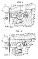
- Figures 4 and 5 are side views of a portion of the embodiment shown in different operative conditions.
- Referring to Figures 1 to 5 which show an embodiment of the present invention, reference numeral 1 designates a printing hammer,
reference numeral 2 denotes a character selecting motor,reference numeral 3 designates an ink or printing ribbon,reference numeral 4 denotes a character wheel,reference numeral 5 designates a containing section or housing for the character wheel, andreference numeral 6 denotes a cradle for the containing housing. Acarrier 7 provided with a printing unit constituted by these is mounted for movement in parallelism to the direction of the axis of aplaten 10 rotatably mounted on a machine bed (not shown), on asupport rod 8 and arail 9 provided on the machine bed (not shown). Thecharacter wheel 4 is mounted chiefly on a vertically movable mounting section ormember 11 as shown in Figure 2, and is contained in containinghousing 5 for upward movement with a predetermined spacing maintained with respect to the latter, and thecradle 6 and thus, the containinghousing 5 is mounted on thecarrier 7 for movement to the left and right as viewed in Figure 1 through aguide rod 12 provided in thecarrier 7, amotor 13, agear 14 and arack 15 provided in thecradle 6. Referring again to Figure 1,reference numeral 16 designates a drive motor provided in the upper portion (the rightward portion as viewed in Figure 1) of one side (the left side as viewed in Figure 2) of thecarrier 7, and agear 18 provided on theshaft 17 of thedrive motor 16 is in meshing engagement with acam gear 19 mounted for rotation on said one side of thecarrier 7. Thecam gear 19 is in meshing engagement with a gear portion 20' provided on the upper edge of ashift arm 20 as a driving member for vertically moving thecharacter wheel 4 which will later be described in detail, a gear portion 21' provided on one side edge of asector plate 21 as a driving member for theprinting ribbon 3 which will later be described in detail, and theaforementioned gear 18, and has no tooth except in the range required for these (i.e., the range indicated by A in Figure 1). Also, the aforementionedcharacter selecting motor 2 is fixed to asupport plate 22 as shown in Figure 3, andpins 23 and 23' projectedly provided on the opposite sides of thesupport plate 22 are fitted inguide holes carrier 7. Further, thesupport plate 22 is connected to a connectingrod 24 mounted for rotation between the side plates 7ʹ and 7ʺ.Pivotable rods 25 and 25ʹ held for pivotal movement relative to the side plates 7ʹ and 7ʺ. byshafts 50 and 50ʹ have their free ends connected to the connectingrod 24. Apin 26 is projectedly provided on one end portion of thepivotable rod 25, and thispin 26 is fitted in aslot cam 27 formed in thecam gear 19. - With the above-described construction, when the
cam gear 19 is rotated, thepins 23 and 23ʹ of thesupport plate 22 are guided by theguide slots -
Reference numerals 28 and 28ʹ designate a pair of straight grooves formed in theopposite side plates carrier 7 to guide a pair ofengaging members 29 and 29ʹ vertically moved by theshift arms 20 and 20ʹ and vertically move thecharacter wheel 4 through theengaging members 29 and 29ʹ Also, theshift arms 20 and 20ʹ, as shown in Figure 2, are connected together by a connectingrod 30 for rotation between the opposite side plates 7ʹ and 7ʺ. and a pair of vertical position controlling V-shaped grooves 31 and 31ʹ are formed in one side edge of the substantially central portion of oneshift arm 20, as shown in Figure l. The pin 33ʹ of a controllingrod 33 pivotably held on the side plate 7' and normally biased in one direction (counter-clockwise direction as viewed in Figure 1) by the force of aspring 32 is engaged with one of the V-shaped grooves 31 and 31'. By this engagement, theshift lever 20 can be temporarily stopped. An ink ribbon mounting section orframe 34 is mounted for pivotal movement on asupport shaft 35 mounted between theopposite side plates 7' and 7". The other end portion of thesector plate 21 is rotatably mounted on thesupport shaft 35, and apin 36 projectedly provided on one side thereof (in a direction perpendicular to the plane of the drawing sheet of Figure 1) is engaged with a slot 34' formed in theribbon frame 34. Acam plate 37 is rotatably mounted on ashaft 38 provided on theribbon frame 34 and is normally biased by the force of aspring 39 provided between the cam plate and the ribbon frame so that the cam surface 37' thereof is engaged with thepin 36 of thesector plate 21. Aprojection 37" projected downwardly of the cam plate (toward this side as viewed in Figure 1) is engaged with a projectedportion 40 provided on the side plate 7' of thecarrier 7, whereby thecam plate 37 can be pivotally moved against the force of thespring 39.Reference numeral 41 designates a connecting pin provided of the shaft 2' of the selectingmotor 2,reference numeral 42 denotes a shaft hole engaged by the shaft 2', andreference numeral 43 designates a connecting hole engaged by the connectingpin 41. - In the above-described construction, a desired
character wheel 4 is moved with thecradle 6 by the revolution of themotor 13 while remaining contained in the containinghousing 5 and comes into engagement with theengaging members 29 and 29ʹ under a position suitable for printing (accordingly, the position of thestraight grooves 28, 28ʹ of the carrier 7), whereafter thedrive motor 16 is operated to rotate thecam gear 19 in the direction of arrow indicated in Figure l by thegear 18 on theshaft 17 thereof. Thereby the gear portion of thecam gear 19 and the gear portion 20ʹ of theshift arm 20 come into meshing engagement with each other to thereby release the engagement between the V-shaped groove 31 in theshift arm 20 and the pin 33ʹ of the controllingrod 33. By further revolution of themotor 16, thecharacter wheel 4 is moved up to a position suitable for printing through theengaging members 29 and 29ʹ - When the
character wheel 4 comes to the position suitable for printing, the gear portion 20ʹ arrives at the untoothed portion of thecam gear 19 and stops thereat and at the same time, by the pivotal movement of the controllingrod 33 caused by the force of thespring 32, the pin 33ʹ thereof is brought into engagement with the V-shaped groove 31ʹ in theshift arm 20, thereby temporarily stopping the shift arm 20 (and accordingly, the character wheel 4) at that position. By the subsequent rotation of thecam gear 19 caused by the rotation of thedrive motor shaft 17, and by the pivotal movement of thepivotable rods 25, and 25ʹ caused by the engagement between theslot cam 27 of thecam gear 19 and thepin 26 of thepivotable rod 25, thecharacter selecting motor 2 is moved toward theplaten 10 with the shaft 2ʹ thereof through thesupport plate 22. By the movement of this character selecting motor, the shaft 2ʹ thereof and the connectingpin 41 are brought into engagement with theshaft hole 42 and connectinghole 43, respectively, in thecharacter wheel 4 located at the position suitable for printing. Thus, thecharacter wheel 4 and the shaft 2ʹ are connected for rotation as a unit and the setting of thecharacter wheel 4 to the position suitable for printing is terminated. By the subsequent rotation of thecam gear 19 caused by the rotation of thedrive motor shaft 17, the gear portion of thegear 19 comes into meshing engagement with the gear portion 21ʹ of thesector plate 21 for the first time, thereby rotating thesector plate 21 in the direction of arrow indicated in Figure l. By this rotation, thepin 36 of the sector plate is caused to strike against the upper end portion 34ʺ of the slot 34ʹ in theribbon frame 34, whereby theribbon frame 34 is pivotally moved in the direction of arrow indicated in Figure l with theprinting ribbon 3, which thus comes to the position suitable for printing, whereupon the revolution of thedrive motor 16 is stopped. In the course of the pivotal movement of the ribbon frame, the projection 37ʺ of thecam plate 37 mounted on theribbon frame 34 becomes disengaged from theprojection 40 provided on the side plate 7ʹ of thecarrier 7, thecam plate 37 is pivotally moved by the biasing force of thespring 39, and the cam surface 37ʹ thereof comes into engagement with thepin 36 on thesector plate 21, thereby making thesector plate 21 and theribbon frame 34 unitary. Thereby, backward movement of theribbon frame 34 may be prevented and theprinting ribbon 3 may be maintained at the printing position. (Figures 4 and 5 show the state in the meantime.) Subsequently, after printing has been terminated, thedrive motor 16 is revolved in the direction opposite to that previously described, whereby each portion may be operated in the direction opposite to that previously described and restores the state before the operation. - Where various types of printing ribbons such as black and red printing ribbons and a printing ribbon for modifying the printing are supported on the ribbon frame and the ribbon frame is to be multistage-shifted as required, this can be accomplished by changing the amount of revolution of the drive motor in conformity with the supported positions of the printing ribbons.
- Accordingly to the present embodiment, as described above, the driving member for locating a desired character wheel at the position suitable for printing from the containing housing for the character wheel and the driving member for locating the printing ribbon at the position suitable for printing are adapted to be drived by the revolution of a single drive motor provided in the carrier and therefore, the weight, volume, etc. of the carrier are reduced as compared with the prior-art carrier, and this is greatly effective to achieve compactness and improved printing speed of the apparatus.
Claims (4)
- A printer of the automatically interchangeable character wheel type for recording on a recording medium, comprising:
a platen (10);
an ink ribbon mounting section (34) capable of mounting an ink ribbon (3);
displacement means (21, 34', 36) for displacing said ink ribbon (3) mounted on said ink ribbon mounting section (34) between a recording position and a retracted position retracted from said recording position; and
a containing section (5) containing a plurality of character wheels (4) having characters; a plurality of character wheel mounting sections (11) each detachably mounting one of said character wheels (4); mounting means (20, 20', 29, 29') for moving to mount a selected one of said character wheels (4) contained in said containing section (5) on its character wheel mounting section (11); a hammer (1) for pressing said characters of said selected character wheel (4) mounted on its character wheel mounting section (11) to said recording medium through said ink ribbon (3) mounted on said ink ribbon mounting section (34)' a common drive source (16, 17, 18, 19) for generating a drive force for driving said displacement means (21, 34', 36) to displace said ink ribbon (3) mounted on said ink ribbon mounting section (34) and a drive force for driving said mounting means (20, 20', 29, 29') to mount said selected character wheel (4) contained in said containing section (5) on its character wheel mounting section (11); and a carrier (7) capable of reciprocally moving along said platen, said carrier (7) having said containing section (5) and said common drive source (16, 17, 18, 19). - A printer according to claim 1, further having rotatively driving means (2, 2', 41) fitted to the selected character wheel (4) to rotate it, and shift means (24, 25, 26, 27) for shifting said rotatively driving means (2, 2', 41) to a position in which it is fitted to the selected character wheel (4) and a position in which it is separated from the selected character holding wheel (4), said shift means being driven by the same drive source (16, 17, 18, 19) as that for said displacement means (21, 34', 36) and said mounting means (20, 20', 29, 29').
- A printer according to one of claims 1 and 2, wherein said drive source (17, 18, 19) comprises a reversible motor (16) and a rotatable member (19) rotated by said motor (16), said displacement means (21, 34', 36) and said mounting means (20, 20', 29, 29') being operated by the rotation of said rotatable member (19) in one direction.
- A printer according to one of claims 1 to 3, wherein said displacement means (21, 34', 36) and said mounting means (20, 20', 29, 29') are driven independently from each other.
Applications Claiming Priority (2)
| Application Number | Priority Date | Filing Date | Title |
|---|---|---|---|
| JP168289/86 | 1986-07-17 | ||
| JP61168289A JPS6325069A (en) | 1986-07-17 | 1986-07-17 | Printer |
Publications (3)
| Publication Number | Publication Date |
|---|---|
| EP0253399A2 EP0253399A2 (en) | 1988-01-20 |
| EP0253399A3 EP0253399A3 (en) | 1988-04-06 |
| EP0253399B1 true EP0253399B1 (en) | 1991-09-11 |
Family
ID=15865261
Family Applications (1)
| Application Number | Title | Priority Date | Filing Date |
|---|---|---|---|
| EP87110315A Expired - Lifetime EP0253399B1 (en) | 1986-07-17 | 1987-07-16 | Printer of the automatically interchangeable character wheel type |
Country Status (4)
| Country | Link |
|---|---|
| US (1) | US5085530A (en) |
| EP (1) | EP0253399B1 (en) |
| JP (1) | JPS6325069A (en) |
| DE (1) | DE3772882D1 (en) |
Citations (4)
| Publication number | Priority date | Publication date | Assignee | Title |
|---|---|---|---|---|
| DE2919209A1 (en) * | 1979-05-12 | 1980-11-13 | Triumph Werke Nuernberg Ag | CONTROL DEVICE FOR TYPEWRITERS |
| US4330218A (en) * | 1979-06-29 | 1982-05-18 | International Business Machines Corporation | Apparatus for connecting and disconnecting a motor and a print element by pivoting a ribbon cartridge |
| JPS5836454A (en) * | 1981-08-25 | 1983-03-03 | Tokyo Electric Co Ltd | Printer |
| US4494884A (en) * | 1982-11-04 | 1985-01-22 | Lowell Herman H | Spoked multiple-wheel printer |
Family Cites Families (12)
| Publication number | Priority date | Publication date | Assignee | Title |
|---|---|---|---|---|
| JPS5193632A (en) * | 1975-02-14 | 1976-08-17 | ||
| BG24518A1 (en) * | 1977-08-25 | 1978-03-10 | Czervendinev | Printing device |
| US4357115A (en) * | 1979-01-02 | 1982-11-02 | Or Michael C P | Printing system for multiple character languages and elements thereof |
| US4289412A (en) * | 1979-11-28 | 1981-09-15 | International Business Machines Corporation | Automatic typefont loader |
| US4307968A (en) * | 1979-11-28 | 1981-12-29 | International Business Machines Corp. | Font changing apparatus for daisy wheel printer |
| US4281938A (en) * | 1980-01-14 | 1981-08-04 | Phillips Stephen R | Automatic print wheel element changing mechanism for a serial printer |
| JPS5839464A (en) * | 1981-09-04 | 1983-03-08 | Silver Seiko Ltd | Printer |
| JPS6023988B2 (en) * | 1981-12-25 | 1985-06-10 | ジューキ株式会社 | Printer ribbon actuator |
| JPS5971879A (en) * | 1982-10-18 | 1984-04-23 | Nec Corp | Serial printer |
| DD218039A1 (en) * | 1983-08-04 | 1985-01-30 | Robotron Bueromasch | METHOD FOR AUTOMATIC TYPE DISC CHANGING AND DEVICE FOR CARRYING OUT THE METHOD |
| DD220262A1 (en) * | 1983-12-22 | 1985-03-27 | Robotron Bueromasch | AUTOMATIC PLATE CHANGE DEVICE IN PRINTERS, WRITTEN OR SIMILAR BUEROUMS |
| DE3677090D1 (en) * | 1985-08-14 | 1991-02-28 | Canon Kk | PRINTER WITH SELF-ACTING TYPE WHEEL CHANGE. |
-
1986
- 1986-07-17 JP JP61168289A patent/JPS6325069A/en active Pending
-
1987
- 1987-07-16 EP EP87110315A patent/EP0253399B1/en not_active Expired - Lifetime
- 1987-07-16 DE DE8787110315T patent/DE3772882D1/en not_active Expired - Lifetime
-
1989
- 1989-12-11 US US07/449,326 patent/US5085530A/en not_active Expired - Lifetime
Patent Citations (4)
| Publication number | Priority date | Publication date | Assignee | Title |
|---|---|---|---|---|
| DE2919209A1 (en) * | 1979-05-12 | 1980-11-13 | Triumph Werke Nuernberg Ag | CONTROL DEVICE FOR TYPEWRITERS |
| US4330218A (en) * | 1979-06-29 | 1982-05-18 | International Business Machines Corporation | Apparatus for connecting and disconnecting a motor and a print element by pivoting a ribbon cartridge |
| JPS5836454A (en) * | 1981-08-25 | 1983-03-03 | Tokyo Electric Co Ltd | Printer |
| US4494884A (en) * | 1982-11-04 | 1985-01-22 | Lowell Herman H | Spoked multiple-wheel printer |
Non-Patent Citations (2)
| Title |
|---|
| IBM Technical Disclosure Bulletin, vol. 18, no. 10, pages 3350 and 3351, March 1976, "Automatic Print Wheel Loader" * |
| IBM Technical Disclosure Bulletin, vol. 23, no. 4, page 1516, September 1980, "Printwheel Removal and Ribbon Cartridge Lifting Mechanism" * |
Also Published As
| Publication number | Publication date |
|---|---|
| EP0253399A3 (en) | 1988-04-06 |
| US5085530A (en) | 1992-02-04 |
| EP0253399A2 (en) | 1988-01-20 |
| JPS6325069A (en) | 1988-02-02 |
| DE3772882D1 (en) | 1991-10-17 |
Similar Documents
| Publication | Publication Date | Title |
|---|---|---|
| US4127335A (en) | Impact printer with cartridge print wheel | |
| US4049109A (en) | Print member carriage assembly | |
| US4389126A (en) | Serial impact printer having two printing modes | |
| JPS591292A (en) | Color printer | |
| US4056183A (en) | Ribbonless endorser having a shiftable inked platen and feed roller | |
| EP0253399B1 (en) | Printer of the automatically interchangeable character wheel type | |
| US4375923A (en) | Rotatable print head for a multiple print station printing apparatus | |
| WO1986004021A1 (en) | Dot matrix printer | |
| EP0212573B1 (en) | Printer of automatic type-wheel exchanging type | |
| US4423973A (en) | Ribbon elevating mechanism for ribbon cassettes | |
| US4842427A (en) | Plotting mechanism mounted on a ribbon cassette for typewriters or office machines | |
| US4865476A (en) | Carriage mechanism providing movement of a print wheel motor | |
| US4511270A (en) | Apparatus for lifting print and correction ribbons in typewriters or like machines | |
| US4402622A (en) | Ink-ribbon lifting apparatus | |
| US5193923A (en) | Automatically interchangeable type wheel type printing apparatus | |
| JPS6330860B2 (en) | ||
| JPS6189066A (en) | Paper treater for printer | |
| JP3061085B2 (en) | Printer ribbon cassette shifter | |
| JP3015681B2 (en) | Printer | |
| US5244289A (en) | Printer having device for adjusting print hammer stroke | |
| JPH0552795B2 (en) | ||
| JP3029773B2 (en) | Printer | |
| JPH0425875B2 (en) | ||
| JPH0367039B2 (en) | ||
| JPS591270A (en) | Printing device |
Legal Events
| Date | Code | Title | Description |
|---|---|---|---|
| PUAI | Public reference made under article 153(3) epc to a published international application that has entered the european phase |
Free format text: ORIGINAL CODE: 0009012 |
|
| AK | Designated contracting states |
Kind code of ref document: A2 Designated state(s): DE FR GB IT |
|
| PUAL | Search report despatched |
Free format text: ORIGINAL CODE: 0009013 |
|
| AK | Designated contracting states |
Kind code of ref document: A3 Designated state(s): DE FR GB IT |
|
| 17P | Request for examination filed |
Effective date: 19880503 |
|
| 17Q | First examination report despatched |
Effective date: 19890714 |
|
| GRAA | (expected) grant |
Free format text: ORIGINAL CODE: 0009210 |
|
| AK | Designated contracting states |
Kind code of ref document: B1 Designated state(s): DE FR GB IT |
|
| REF | Corresponds to: |
Ref document number: 3772882 Country of ref document: DE Date of ref document: 19911017 |
|
| ITF | It: translation for a ep patent filed |
Owner name: SOCIETA' ITALIANA BREVETTI S.P.A. |
|
| ET | Fr: translation filed | ||
| PLBE | No opposition filed within time limit |
Free format text: ORIGINAL CODE: 0009261 |
|
| STAA | Information on the status of an ep patent application or granted ep patent |
Free format text: STATUS: NO OPPOSITION FILED WITHIN TIME LIMIT |
|
| 26N | No opposition filed | ||
| REG | Reference to a national code |
Ref country code: GB Ref legal event code: IF02 |
|
| PGFP | Annual fee paid to national office [announced via postgrant information from national office to epo] |
Ref country code: FR Payment date: 20050708 Year of fee payment: 19 |
|
| PGFP | Annual fee paid to national office [announced via postgrant information from national office to epo] |
Ref country code: GB Payment date: 20050713 Year of fee payment: 19 |
|
| PGFP | Annual fee paid to national office [announced via postgrant information from national office to epo] |
Ref country code: DE Payment date: 20050714 Year of fee payment: 19 |
|
| PG25 | Lapsed in a contracting state [announced via postgrant information from national office to epo] |
Ref country code: GB Free format text: LAPSE BECAUSE OF NON-PAYMENT OF DUE FEES Effective date: 20060716 |
|
| PGFP | Annual fee paid to national office [announced via postgrant information from national office to epo] |
Ref country code: IT Payment date: 20060731 Year of fee payment: 20 |
|
| PG25 | Lapsed in a contracting state [announced via postgrant information from national office to epo] |
Ref country code: DE Free format text: LAPSE BECAUSE OF NON-PAYMENT OF DUE FEES Effective date: 20070201 |
|
| GBPC | Gb: european patent ceased through non-payment of renewal fee |
Effective date: 20060716 |
|
| REG | Reference to a national code |
Ref country code: FR Ref legal event code: ST Effective date: 20070330 |
|
| PG25 | Lapsed in a contracting state [announced via postgrant information from national office to epo] |
Ref country code: FR Free format text: LAPSE BECAUSE OF NON-PAYMENT OF DUE FEES Effective date: 20060731 |