EP0252268A2 - Process for monitoring the machining energy source, particularly with a laser, and machining optics for its implementation - Google Patents
Process for monitoring the machining energy source, particularly with a laser, and machining optics for its implementation Download PDFInfo
- Publication number
- EP0252268A2 EP0252268A2 EP87107712A EP87107712A EP0252268A2 EP 0252268 A2 EP0252268 A2 EP 0252268A2 EP 87107712 A EP87107712 A EP 87107712A EP 87107712 A EP87107712 A EP 87107712A EP 0252268 A2 EP0252268 A2 EP 0252268A2
- Authority
- EP
- European Patent Office
- Prior art keywords
- mirror
- laser
- focusing
- deflecting
- processing optics
- Prior art date
- Legal status (The legal status is an assumption and is not a legal conclusion. Google has not performed a legal analysis and makes no representation as to the accuracy of the status listed.)
- Granted
Links
Images


Classifications
-
- B—PERFORMING OPERATIONS; TRANSPORTING
- B23—MACHINE TOOLS; METAL-WORKING NOT OTHERWISE PROVIDED FOR
- B23K—SOLDERING OR UNSOLDERING; WELDING; CLADDING OR PLATING BY SOLDERING OR WELDING; CUTTING BY APPLYING HEAT LOCALLY, e.g. FLAME CUTTING; WORKING BY LASER BEAM
- B23K26/00—Working by laser beam, e.g. welding, cutting or boring
- B23K26/02—Positioning or observing the workpiece, e.g. with respect to the point of impact; Aligning, aiming or focusing the laser beam
- B23K26/06—Shaping the laser beam, e.g. by masks or multi-focusing
- B23K26/064—Shaping the laser beam, e.g. by masks or multi-focusing by means of optical elements, e.g. lenses, mirrors or prisms
- B23K26/0643—Shaping the laser beam, e.g. by masks or multi-focusing by means of optical elements, e.g. lenses, mirrors or prisms comprising mirrors
-
- B—PERFORMING OPERATIONS; TRANSPORTING
- B23—MACHINE TOOLS; METAL-WORKING NOT OTHERWISE PROVIDED FOR
- B23K—SOLDERING OR UNSOLDERING; WELDING; CLADDING OR PLATING BY SOLDERING OR WELDING; CUTTING BY APPLYING HEAT LOCALLY, e.g. FLAME CUTTING; WORKING BY LASER BEAM
- B23K26/00—Working by laser beam, e.g. welding, cutting or boring
- B23K26/02—Positioning or observing the workpiece, e.g. with respect to the point of impact; Aligning, aiming or focusing the laser beam
- B23K26/03—Observing, e.g. monitoring, the workpiece
- B23K26/034—Observing the temperature of the workpiece
-
- B—PERFORMING OPERATIONS; TRANSPORTING
- B23—MACHINE TOOLS; METAL-WORKING NOT OTHERWISE PROVIDED FOR
- B23K—SOLDERING OR UNSOLDERING; WELDING; CLADDING OR PLATING BY SOLDERING OR WELDING; CUTTING BY APPLYING HEAT LOCALLY, e.g. FLAME CUTTING; WORKING BY LASER BEAM
- B23K26/00—Working by laser beam, e.g. welding, cutting or boring
- B23K26/02—Positioning or observing the workpiece, e.g. with respect to the point of impact; Aligning, aiming or focusing the laser beam
- B23K26/04—Automatically aligning, aiming or focusing the laser beam, e.g. using the back-scattered light
-
- B—PERFORMING OPERATIONS; TRANSPORTING
- B23—MACHINE TOOLS; METAL-WORKING NOT OTHERWISE PROVIDED FOR
- B23K—SOLDERING OR UNSOLDERING; WELDING; CLADDING OR PLATING BY SOLDERING OR WELDING; CUTTING BY APPLYING HEAT LOCALLY, e.g. FLAME CUTTING; WORKING BY LASER BEAM
- B23K26/00—Working by laser beam, e.g. welding, cutting or boring
- B23K26/70—Auxiliary operations or equipment
- B23K26/702—Auxiliary equipment
- B23K26/703—Cooling arrangements
-
- B—PERFORMING OPERATIONS; TRANSPORTING
- B23—MACHINE TOOLS; METAL-WORKING NOT OTHERWISE PROVIDED FOR
- B23K—SOLDERING OR UNSOLDERING; WELDING; CLADDING OR PLATING BY SOLDERING OR WELDING; CUTTING BY APPLYING HEAT LOCALLY, e.g. FLAME CUTTING; WORKING BY LASER BEAM
- B23K26/00—Working by laser beam, e.g. welding, cutting or boring
- B23K26/70—Auxiliary operations or equipment
- B23K26/702—Auxiliary equipment
- B23K26/705—Beam measuring device
-
- B—PERFORMING OPERATIONS; TRANSPORTING
- B23—MACHINE TOOLS; METAL-WORKING NOT OTHERWISE PROVIDED FOR
- B23K—SOLDERING OR UNSOLDERING; WELDING; CLADDING OR PLATING BY SOLDERING OR WELDING; CUTTING BY APPLYING HEAT LOCALLY, e.g. FLAME CUTTING; WORKING BY LASER BEAM
- B23K26/00—Working by laser beam, e.g. welding, cutting or boring
- B23K26/70—Auxiliary operations or equipment
- B23K26/702—Auxiliary equipment
- B23K26/707—Auxiliary equipment for monitoring laser beam transmission optics
Definitions
- the invention relates to a method for monitoring the machining process with a high-power energy source, in particular a laser, according to the preamble of claim 1 and a machining optics for carrying out the method according to the preamble of claim 9.
- High-performance energy sources in particular electron beams or focused laser beams (CO2 lasers) that are used for material processing, namely cutting, welding and surface finishing, have appropriate beam-guiding optics that are adapted to the respective processing task.
- the processing optics of the laser which have a significant influence, are particularly important the quality of the processing to be carried out. In order to ensure the best possible processing quality that remains as constant as possible during the entire machining process, it is necessary to keep the machining process on the workpiece constant.
- the decisive beam sizes are the beam power, the beam diameter, the position of the beam and the reflected radiation, which can be subject to fluctuations in time during processing and must therefore be taken into account.
- the object of the invention is therefore to provide a method and a processing optics for monitoring the processing process of a high-power laser (CO2 laser), whereby the essential factors influencing the quality of the material processing can be determined.
- CO2 laser high-power laser
- the characteristic features of claim 1 serve to solve this problem with regard to the method.
- the fact that the relevant influencing variables of the laser beam are measured during the material processing creates the possibility for comprehensive integrated process monitoring, specifically where the measurement is not only complete but also can also be carried out most simply and reliably, namely on the processing optics.
- This also has advantages if the laser is to be used for other processing operations that do not require any processing optics or other processing optics, because then the sensitive measuring instruments that are no longer necessary in such cases no longer have to remain unused on the device.
- the processing optics are expediently used to measure the power of the laser beam, the position of the laser beam relative to the optical axis, the diameter of the laser beam, the degree of contamination of the mirror (deflecting mirror, focusing mirror) and the reflecting back required laser radiation due to appropriately designed sensors or transducers.
- the above-mentioned influencing variables are measured in a comulative manner.
- the characteristic feature of claim 9 is used to solve the problem with regard to the processing optics. By assigning appropriate measuring transducers (detectors) to the deflecting mirror and the focusing mirror of the processing optics, the measured variables are picked up directly where possible deviations can occur and have an influence on them the same may be exercised. In addition, disruptive measurement installations in the processing optics are avoided.
- a high-power laser namely a CO2 laser 20 serves as the energy source.
- a telescope 21 At the radiation output of the CO2 laser 20 there is a telescope 21.
- the latter is connected via a (horizontal) protective tube 22 to a beam deflecting lens 23. This deflects the laser beam coming through the protective tube 22 from the horizontal into a vertical beam direction.
- the laser beam finally arrives from the beam deflecting optics 23 through a further (vertical) protective tube 24 to the processing optics 25.
- the processing optics 25 is designed such that the laser beam is deflected twice in it, namely by a deflecting mirror 26 from a vertical to a horizontal beam direction and from this in turn by a focusing mirror 27 in a right angle thereto Direction of exit of the laser beam from the processing optics.
- FIGS. 2 and 5 the structure of the processing optics 25 can be seen from FIGS. 2 and 5. Accordingly, this has an elongated, horizontally lying housing 30 with a square cross section. A longitudinal, circular through-bore 31 is arranged in the center of the housing 30. The opposite end faces of the housing 30 are closed by a flange-like cover 32 and 33, respectively.
- the housing 30 has at least two openings in its walls, namely an upper entry opening 34 for the laser beam coming from the beam deflecting optics 23 and an exit opening 35 for the exit of the focused laser beam 28 from the processing optics 25.
- the mirrors required for deflecting the laser beam are also arranged in the housing 30 of the processing optics 25.
- the inlet opening 34 is assigned the cylindrically designed deflection mirror 26 with a flat mirror surface 36 inclined at 45 °. This deflects the laser beam entering vertically into the processing optics 25 onto a laser beam that continues horizontally to the focusing mirror 27.
- the likewise cylindrical focusing mirror 27 is arranged on the side opposite the deflecting mirror 26 in the housing 30 and has a mirror surface 37 which is also 45 °, but is rotationally symmetrical concave.
- the mirrors (deflecting mirror 26; focusing mirror 27), which are guided centrally in the housing 30, are fastened by means of a (central) threaded screw 38 to the associated cover 32 or 33.
- each mirror (deflecting mirror 26; focusing mirror 27) is assigned a thermal resistance 39 or 40.
- the thermal resistance 40 is arranged between the deflecting mirror 26 and the cover 33 associated with the latter, namely in contact with the flat, upright rear side 41 of the deflecting mirror 26 on the one hand and the inner end face 42 of the cover 33 directed towards the same.
- the deflecting mirror 40 is designed as a circular disk with parallel, upright contact surfaces 43.
- a correspondingly dimensioned recess 44 in the cover 33 and a sufficiently large through hole 45 in the middle of the thermal resistor 40 ensure that the latter does not receive any contact with the cover 33 or the threaded screw 38 on the lateral surfaces.
- only the contact surfaces 33 of the thermal resistor 40 rest against the rear side 41 of the deflecting mirror 26 and the inner end face 42 of the cover 33.
- a thin bore 46 runs obliquely through the cover 33 and through the thermal resistance 40 and opens into the contact surface 43 of the deflecting mirror 26.
- Another obliquely directed bore 47 in the cover 33 opens in front of the (outer) contact surface 43 of the thermal resistor 40 directed toward the same.
- the ends of the bores 46 and 47 directed towards the outside of the cover 33 are provided with clearances 48.
- corresponding detectors (not shown in FIGS. 2 and 3) can be accommodated in the cover 33, in such a way that their sensor tips rest against the rear side 41 of the deflection mirror 26 on the one hand and the (outer) contact surface 43 of the thermal resistor 40 on the other hand lead to.
- the detectors or the sensor tips thereof are preferably designed as thermocouples - known per se.
- the thermal resistance 39 is designed in an analogous manner and is arranged behind the focusing mirror 27, with corresponding bores 46 and 47 also being provided here for the assignment of sensor tips to corresponding detectors to the rear side 41 of the focusing mirror 27 and to the contact surface 43 of the thermal resistance 39.
- the heat resistors 39 and 40 are used to measure the beam power and the degree of contamination of the focusing mirror 27. It is based on the knowledge that the processing optics 25 are only significantly contaminated on the focusing mirror 27, namely on the mirror surface 37 thereof, because only that above the workpiece 29 horizontal focusing mirror 27 negative influences due to workpiece machining is exposed. In contrast, contamination of the deflection mirror 26, which is protected in the processing optics 25, is not to be expected. The degree of soiling of the focusing mirror 27 therefore results from a difference measurement between the temperatures at the deflecting mirror 26 and at the focusing mirror 27. For this purpose, both thermal resistors 39 and 40 have the same cross-section, the same thickness and the same heat transmission time.
- the beam power is measured at the deflecting mirror 26, specifically by determining the temperature gradient between the contact surface 43 of the thermal resistor 40 directed towards the rear side 41 of the deflecting mirror 26 on the one hand and with the opposite contact surface 43 of the thermal resistor 40 directed towards the inner end face 42 of the cover 33 of the beam power changing measurement value, whereby the beam power impinging on the deflecting mirror 26 can be determined directly from the temperature gradient as a result of multiplication with a corresponding transmission coefficient.
- radially directed slots 49 are arranged both in the deflecting mirror 26 and in the focusing mirror 27. These break through the corresponding mirror surfaces 36 and 37 as well as the cylindrical outer surface of the mirrors (deflecting mirror 26; focusing mirror 27) in narrow, elongated areas.
- the slots 49 are distributed symmetrically with respect to mirror surfaces 36 and 37 of the mirrors (deflecting mirror 26; focusing mirror 27). In the present case, three slots 49, each offset by 120 °, are provided (FIG. 4).
- the slots 49 emanating from the lateral surface of the mirrors (deflecting mirror 26; focusing mirror 27) are all on the center 50 of FIG Mirror surfaces 36 and 37 directed and end without touching at a slight distance from the same.
- the mirrors deflecting mirror 26; focusing mirror 27
- the width of the slots 49 is chosen such that it is larger than the wavelength of the laser, for example 0.4 mm. This ensures that the reduction in the effective mirror surface 36 or 37 resulting from the slits 49 is negligibly small, that is to say the effective laser power due to the regions of the laser beam which are masked out in the region of the slits 49 is hardly significant.
- the slots 49 do not go through to the rear sides 41 of the mirrors (deflecting mirror 26; focusing mirror 27).
- the resulting underside of the slot 51 is curved, in such a way that the areas of the laser beam directed into the slots 49 from the mirror surface 36 and 37, respectively, of the laser beam directed in the longitudinal direction to the axis of the mirror (deflection mirror 26; focusing mirror 27) on the underside 51 of the slot be deflected and focused approximately 90 ° radially outward.
- the focal points 52 of the areas of the laser beam which enter the slots 49 and are deflected on the underside 51 of the slot lie at a distance from the lateral surface outside the mirrors (deflecting mirror 26; focusing mirror 27).
- this configuration of the slots 49 ensures that only partial areas of the laser beams incident in the longitudinal direction of the mirrors (deflecting mirror 26; focusing mirror 27) fall on the underside of the slot 51, that is to say transverse laser beams do not affect the slots 49.
- corresponding ones can also be used segments protruding from the mirror surfaces 36, 37 for guiding the regions of the laser beam intended for measurement to the mirrors (deflecting mirror 26; focusing mirror 27).
- Each of the focus points 52 is assigned a detector 53, which is mounted at a radial distance from the mirrors (deflection mirror 26; focusing mirror 27) in the housing 30 of the processing optics 25.
- the detectors 53 are preferably designed as a thermopile of a commercially available type, which allow optimal implementation of the infrared signals entering the slots 49.
- the measurement signals of the detectors 23 assigned to the focusing mirror 27 are added, that is to say an evaluation of the laser beams entering through the slots 49 in the focusing mirror 27.
- the power flux density of the laser beam - which is constant with respect to the cross section of the laser beam - can be determined from the measurement of the total beam power described at the beginning, this value can be taken into account from this value, taking into account the dimensions of the slots 49, the number of these and the measurement results on the detectors 53 with a circular laser beam, the beam diameter can be determined.
- the slots 49 and detectors 53 assigned to the focusing mirror 27 also serve for the second measurement task, namely the determination of the position of the laser beam relative to the optical axis 54.
- the evaluation is not carried out here by summing the measurement results at the individual detectors 53: the Relative position of the laser beam determined by differential measurements of the power incident in the (infrared) detectors 53 by determining the center of gravity of the laser beam with respect to the optical axis 54. If there are three slits 49 on the mirror surface 36 of the focusing mirror 27, the center of gravity of the laser beam is obtained by evaluation using a polar coordinate system. On the other hand, if four slots are used, the evaluation can be carried out in a Cartesian coordinate system.
- the (detection) slots 49 can also be used to determine the laser radiation reflected back by the workpiece 29.
- the slots 49 arranged in the deflecting mirror 26 and the detectors 53 assigned to them serve for this purpose.
- conclusions can be drawn about the coupling of the laser beam on the workpiece 29.
- a weld seam can be found or tracked by assigning corresponding actuators to the processing optics 25, which, depending on the measurement result on the deflection mirror 26, move the processing optics 25 relative to the workpiece 29 until the retroreflected laser beams have reached a minimum, which is an indication of this is that an optimum of the laser radiation is absorbed by the workpiece 29, that is, the weld seam or the like has been found.
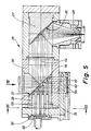
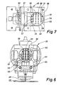
- FIG. 5 to 7 show an alternative embodiment of a processing optics 25 in which a plurality of bores distributed in a grid pattern on the mirror surfaces 36 and 37 of the mirrors instead of the slots 49 present in the exemplary embodiment described above, for measuring the beam position, the beam diameter and the reflected back laser beams are provided.
- the bores are arranged exclusively in the deflecting mirror 26, specifically as Through bores 55 running parallel to the longitudinal center line thereof and through bores 56 running transversely thereto.
- the through bores have a very small diameter to the mirror surface 37, namely only about 0.5 mm.
- the diameters of the through bores 55 and 56 increase in steps.
- FIG. 7 shows the grid according to which the through bores 55 and 26 are distributed over the mirror surface 37 of the deflecting mirror 26. Accordingly, a total of 24 through bores are provided here, namely 12 (horizontal) through bores 55 and also 12 (vertical) through bores 56. These are on four horizontal rows 54 and seven vertical rows 57 and 58 over a reduced number of through bores 55 and 56 have. 7 by partial blackening of the through bores 55 and 56 indicates whether these are combined to form a vertical or horizontal measuring string. Accordingly, the un-blackened through holes 55 and 56 form the horizontal measuring strands, while the semi-blackened through holes 55 and 56 form the vertical measuring strands. From this it can be seen that three vertical measuring strands and four horizontal measuring strands are provided in the present exemplary embodiment.
- the horizontal through bores 55 are continued in some areas in the cover 33 and are connected by a bore 60 directed transversely thereto.
- This is used to accommodate one or more suitable detectors, for example resistance thermometers made of wire. These can either run continuously over the entire measuring strand (row 58), but can also be divided in the middle, so that each measuring strand (row 58) two detectors 59 in the form of resistance thermometers are assigned.
- the detectors 61 can be designed in an analogous manner, namely also as resistance thermometers, which are accommodated in bores 62 running transversely to the vertical through bores 56 in the housing 30 of the processing optics 25.
- the diameter and the position of the incoming laser beam at the deflecting mirror 26 are measured with the aid of the vertical through holes 56, while the position, the power - and possibly the diameter - of the laser light reflected back from the workpiece 29 are measured with the aid of the horizontal through holes 55.
- the evaluation of the measurement results obtained at the detectors 59 and 61 takes place here in a manner similar to that in the exemplary embodiment described above with (detection) slots 49 arranged in the mirrors (deflection mirror 26; focusing mirror 27).
- the through holes 55 and 56 can also be distributed in this embodiment of the processing optics 55 according to the invention on the deflecting mirror 26 and the focusing mirror 27, so that each mirror would then only have either vertical or horizontal through holes.
- FIGS. 8 to 11 show an exemplary embodiment of the processing optics 25 according to the invention, in which sensors 63 which absorb directly on the mirror surface 37 of the deflecting mirror 26 are arranged.
- the sensors 63 can be designed as wire-shaped resistance thermometers.
- the course of the sensors 63 arranged here on the mirror surface 37 of the deflecting mirror 26 can be seen in FIG. 9. Accordingly, four sensors 63 made of U-shaped coiled wire are arranged so as to run radially evenly distributed on the mirror surface 37 without meeting in the center 50 of the mirror surface 37.
- the 10 shows the attachment of the sensors 63 on the mirror surface 37 of the deflecting mirror 26.
- approximately semicircular recesses 64 for the sensors 63 are arranged on the mirror surface 37, the majority of which are filled with an insulator 65 by in each case a wire for the sensor 63 being embedded such that the mirror surface 37 remains flat despite the sensors 63 arranged thereon .
- the insulator 65 preferably consists of an adhesive for permanently fixing the wire for the sensors 63 in the recesses 64 of the deflection mirror 26.
- FIG. 11 An alternative embodiment of the attachment of the sensors 63 on the mirror surface 37 of the deflecting mirror 26 is shown in FIG. 11.
- the sensors 63 - which can also have the course shown in FIG. 9 - are raised on the mirror surface 37.
- the sensors 63 are formed from a thin, layer-shaped conductor which is connected to the mirror surface 37 by an insulation layer 66.
- Such sensors 63 can be produced, for example, by vapor deposition on the mirror surface 37 of the deflecting mirror 26.
Abstract
Die Bearbeitungsergbnisse von Hochleistungslasern mit Bearbeitungsoptiken (25) zur Strahlformung hängen davon ab, daß ausschlaggebende Bearbeitungsgrößen, nämlich die Strahlleistung, der Strahldurchmesser, die Lage des Strahls relativ zur optischen Achse (54) und die Intensität der rückflektierten Strahlung überwacht werden. Zu diesem Zweck schlägt die Erfindung ein Verfahren vor, mit dem direkt an einer entsprechend erfindungsgemäß ausgestalteten Bearbeitungsoptik (25) die wesentlichen Strahlgrößen während der Bearbeitung gemessen werden können. Dazu sind die entsprechenden Meßwertaufnehmer erfindungsgemäß dem Umlenkspiegel (26) und/oder dem Fokussierspiegel (27) der Bearbeitungsoptik (25) zugeordnet.The processing results of high-power lasers with processing optics (25) for beam shaping depend on the fact that decisive processing variables, namely the beam power, the beam diameter, the position of the beam relative to the optical axis (54) and the intensity of the reflected radiation are monitored. For this purpose, the invention proposes a method with which the essential beam sizes can be measured directly on a processing optics (25) designed according to the invention. For this purpose, the corresponding sensors are assigned to the deflecting mirror (26) and / or the focusing mirror (27) of the processing optics (25).
Description
Die Erfindung betrifft ein Verfahren zur Überwachung des Bearbeitungsprozesses mit einer Hochleistungsenergiequelle, insbesondere einem Laser, gemäß dem Oberbegriff des Anspruchs 1 und eine Bearbeitungsoptik zur Durchführung des Verfahrens gemäß dem Oberbegriffs des Anspruchs 9.The invention relates to a method for monitoring the machining process with a high-power energy source, in particular a laser, according to the preamble of claim 1 and a machining optics for carrying out the method according to the preamble of claim 9.
Hochleistungsenergiequellen, und zwar insbesondere Elektronenstrahlen oder fokussierte Laserstrahlen (CO₂Laser) die zur Materialbearbeitung, nämlich Schneiden, Schweißen und Oberflächenveredeln eingesetzt werden, verfügen über entsprechende strahlführende Optiken, welche an die jeweilige Bearbeitungsaufgabe angepaßt sind. In diesem Zusammenhang kommt es besonders auf die Bearbeitungsoptik des Lasers an, die wesentlichen Einfluß an der Qualität der durchzuführenden Bearbeitung hat. Um während der gesamten Bearbeitung eine möglichst gleichbleibende, optimale Bearbeitungsqualität zu gewährleisten, ist es erforderlich, den Bearbeitungsvorgang am Werkstück konstant zu halten.High-performance energy sources, in particular electron beams or focused laser beams (CO₂ lasers) that are used for material processing, namely cutting, welding and surface finishing, have appropriate beam-guiding optics that are adapted to the respective processing task. In this context, the processing optics of the laser, which have a significant influence, are particularly important the quality of the processing to be carried out. In order to ensure the best possible processing quality that remains as constant as possible during the entire machining process, it is necessary to keep the machining process on the workpiece constant.
Zu diesem Zweck sind die ausschlaggebenden Strahlgrößen die Strahlleistung, der Strahldurchmesser, die Lage des Strahls und die zurückreflektierte Strahlung, die während der Bearbeitung zeitlichen Schwankungen unterliegen können und daher berücksichtigt werden müssen.For this purpose, the decisive beam sizes are the beam power, the beam diameter, the position of the beam and the reflected radiation, which can be subject to fluctuations in time during processing and must therefore be taken into account.
Aufgabe der Erfindung ist es daher, ein Verfahren und eine Bearbeitungsoptik zur Überwachung des Bearbeitungsprozesses eines Hochleistungslasers (CO₂-Laser) anzugeben, wodurch sich die wesentlichen Einflußgrößen auf die Qualität der Materialbearbeitung ermitteln lassen.The object of the invention is therefore to provide a method and a processing optics for monitoring the processing process of a high-power laser (CO₂ laser), whereby the essential factors influencing the quality of the material processing can be determined.
Zur Lösung dieser Aufgabe hinsichtlich des Verfahrens dienen die kennzeichnenden Merkmale des Anspruchs 1. Dadurch, daß während der Materialbearbeitung die maßgeblichen Einflußgrößen des Laserstrahls gemessen werden, wird die Möglichkeit zur umfassenden integrierten Prozeßüberwachung geschaffen, und zwar dort, wo die Messung nicht nur komplett, sondern auch am einfachsten und zuverlässigsten durchführbar ist, nämlich an der Bearbeitungsoptik. Dieses hat auch Vorteile, wenn der Laser für andere Bearbeitungen eingesetzt werden soll, die keine Bearbeitungsoptik oder eine andere Bearbeitungsoptik erfordern, weil dann nämlich die in solchen Fällen nicht mehr notwendigen, empfindlichen Meßinstrumente nicht mehr ungenutzt am Gerät verbleiben müssen.The characteristic features of claim 1 serve to solve this problem with regard to the method. The fact that the relevant influencing variables of the laser beam are measured during the material processing creates the possibility for comprehensive integrated process monitoring, specifically where the measurement is not only complete but also can also be carried out most simply and reliably, namely on the processing optics. This also has advantages if the laser is to be used for other processing operations that do not require any processing optics or other processing optics, because then the sensitive measuring instruments that are no longer necessary in such cases no longer have to remain unused on the device.
Zweckmäßigerweise erfolgt an der Bearbeitungsoptik die Messung der für die Leistung des Laserstrahls, die Position desselben zur optischen Achse, des Durchmessers des Laserstrahls, des Verschmutzungsgrades der Spiegel (Umlenkspiegel, Fokussierspiegel) und der zurückreflektier ten Laserstrahlung erforderliche Größen durch entsprechend gestaltete Meßwertaufnehmer bzw. -umformer. Bei einer besonders bevorzugten Ausführungsform des erfindungsgemäßen Verfahrens erfolgt die Messung der vorstehend genannten Einflußgrößen komulativ.The processing optics are expediently used to measure the power of the laser beam, the position of the laser beam relative to the optical axis, the diameter of the laser beam, the degree of contamination of the mirror (deflecting mirror, focusing mirror) and the reflecting back required laser radiation due to appropriately designed sensors or transducers. In a particularly preferred embodiment of the method according to the invention, the above-mentioned influencing variables are measured in a comulative manner.
Durch entsprechende Umformung der Meßergebnisse ist es möglich, diese direkt entsprechenden Stellantrieben etc. zuzuleiten, die - bei Abweichungen vom Sollwert - entsprechende Korrekturen an der Strahlführung des Lasers vornehmen. Weitere Unteransprüche beziehen sich auf die Verfahren zur Ermittlung der jeweiligen Meßwerte.By appropriately reshaping the measurement results, it is possible to feed these directly to corresponding actuators, etc., which - in the event of deviations from the target value - make corresponding corrections to the beam guidance of the laser. Further sub-claims relate to the methods for determining the respective measured values.
Zur Lösung der Aufgabe in bezug auf die Bearbeitungsoptik dient das kennzeichnende Merkmal des Anspruchs 9. Durch die Zuordnung ensprechender Meßumformer (Detektoren) zu dem Umlenkspiegel und dem Fokussierspiegel der Bearbeitungsoptik erfolgt ein Abgreifen der Meßgrößen unmittelbar dort, wo eventuelle Abweichungen zustandekommen können und ein Einfluß auf dieselben ggf. auszuüben ist. Darüber hinaus werden störende Meßeinbauten in der Bearbeitungsoptik vermieden.The characteristic feature of claim 9 is used to solve the problem with regard to the processing optics. By assigning appropriate measuring transducers (detectors) to the deflecting mirror and the focusing mirror of the processing optics, the measured variables are picked up directly where possible deviations can occur and have an influence on them the same may be exercised. In addition, disruptive measurement installations in the processing optics are avoided.
Weitere den Unteransprüchen zu entnehmende Merkmale in bezug auf die erfindungsgemäße Bearbeitungsoptik betreffen die konstruktive Ausbildung der Meßwertaufnehmer bzw. -umformer am Umlenkspiegel und Fokussierspiegel zur Ermittlung der speziellen Meßwerte.Further features to be taken from the subclaims with regard to the processing optics according to the invention relate to the structural design of the measured value transducers or converters on the deflecting mirror and focusing mirror for determining the special measured values.
Bevorzugte Ausführungsbeispiele der Erfindung werden nachfolgend anhand der Zeichnungen näher erläutert.Preferred exemplary embodiments of the invention are explained in more detail below with reference to the drawings.
Es zeigen:
- Fig. 1 den schematischen Aufbau einer Laser-Bearbeitungsvorrichtung in perspektivischer Darstellung,
- Fig. 2 einen vertikalen Längsschnitt durch eine Bearbeitungsoptik gemäß eines ersten Ausführungsbeispiels,
- Fig. 3 eine Seitenansicht eines umliegenden Spiegels mit einem vertikal geschnittenen Gehäusedeckel und einem dazwischen angeordneten Wärmewiderstand,
- Fig. 4 eine Querschnitt durch die Bearbeitungsoptik gemäß der Fig. 2 in der Ebene dreier dem Umlenkspiegel zugeordneten Detektoren,
- Fig. 5 einen vertikalen Längsschnitt durch eine Bearbeitungsoptik eines zweiten Ausführungsbeispiels,
- Fig. 6 einen Schnitt VI-VI durch die Bearbeitungsoptik gemäß Fig. 5,
- Fig. 7 eine Ansicht in Richtung des Pfeils VII auf die Spiegelfläche des Umlenkspiegels,
- Fig. 8 einen Umlenkspiegel mit auf der Spiegelfläche angeordneten Sensoren,
- Fig. 9 eine Draufsicht auf die Spiegelfläche des Umlenkspiegels gemäß der Fig. 8,
- Fig. 10 eine vergrößert dargestellte Einzelheit X des im Bereich eines Sensors geschnittenen Umlenkspiegels gemäß der Fig. 8, und
- Fig. 11 eine alternative Ausführungsform zur Anordnung der Sensoren auf der Spiegelfläche des Umlenkspiegels in einer Darstellung gemäß der Fig. 10.
- 1 shows the schematic structure of a laser processing device in a perspective view,
- 2 shows a vertical longitudinal section through processing optics according to a first exemplary embodiment,
- 3 is a side view of a surrounding mirror with a vertically cut housing cover and a thermal resistance arranged in between,
- 4 shows a cross section through the processing optics according to FIG. 2 in the plane of three detectors assigned to the deflecting mirror,
- 5 shows a vertical longitudinal section through processing optics of a second exemplary embodiment,
- 6 shows a section VI-VI through the processing optics according to FIG. 5,
- 7 is a view in the direction of arrow VII on the mirror surface of the deflecting mirror,
- 8 shows a deflecting mirror with sensors arranged on the mirror surface,
- 9 is a plan view of the mirror surface of the deflecting mirror according to FIG. 8,
- 10 shows an enlarged detail X of the deflecting mirror cut in the area of a sensor according to FIGS. 8, and
- 11 shows an alternative embodiment for the arrangement of the sensors on the mirror surface of the deflecting mirror in a representation according to FIG. 10.
Aus der Fig. 1 geht anschaulich der prinzipielle Aufbau eines Lasers zur Verwirklichung des erfindungsgemäßen Verfahrens mit der erfindungsgemäßen Bearbeitungsoptik hervor. Als Energiequelle dient hier ein Hochleistungslaser, nämlich ein CO₂-Laser 20. Am Strahlenausgang des CO₂-Lasers 20 befindet sich ein Teleskop 21. Letzteres ist über ein (horizontales) Schutzrohr 22 mit einer Strahlenumlenkoptik 23 verbunden. Durch diese wird der durch das Schutzrohr 22 kommende Laserstrahl aus der horizontalen in eine vertikale Strahlrichtung umgelenkt. Von der Strahlumlenkoptik 23 gelangt der Laserstrahl schließlich durch ein weiteres (vertikales) Schutzrohr 24 zu der Bearbeitungsoptik 25.1 clearly shows the basic structure of a laser for realizing the method according to the invention with the processing optics according to the invention. A high-power laser, namely a
Wie die Fig. 2 und 5 zeigen, ist die Bearbeitungsoptik 25 derart ausgebildet, daß der Laserstrahl in ihr zweimal umgelenkt wird, und zwar durch einen Umlenkspiegel 26 von einer vertikalen in eine horizontale Strahlrichtung und von dieser wiederum durch einen Fokussierspiegel 27 in eine dazu rechtwinklige Austrittsrichtung des Laserstrahls aus der Bearbeitungsoptik.2 and 5 show, the
Den Fig. 2 und 5 ist weiterhin zu entnehmen, daß der Laserstrahl als fokussierter Laserstrahl 28 die Bearbeitungsoptik 25 in vertikaler Richtung verläßt. Mit einem derart fokussierten Laserstrahl 28 lassen sich sowohl Schneid-, Schweiß- als auch Oberflächenveredelungsbearbeitungen an einem Werkstück 29 (Fig. 1) durchführen.2 and 5 that the laser beam as a focused
Schließlich kann den Fig. 2 und 5 noch der Aufbau der Bearbeitungsoptik 25 entnommen werden. Demnach verfügt diese über ein längliches, horizontalliegendes Gehäuse 30 mit einem quadratischen Querschnitt. Im Gehäuse 30 ist mittig eine längsgerichtete, kreisrunde Durchgangsbohrung 31 angeordnet. Die gegenüberliegende Stirnseiten des Gehäuses 30 sind durch jeweils einen flanschartig ausgebildeten Deckel 32 bzw. 33 verschlossen.Finally, the structure of the
Das Gehäuse 30 weist mindestens zwei Öffnungen in seinen Wandungen auf, und zwar eine obere Eintrittsöffnung 34 für den von der Strahlumlenkoptik 23 kommenden Laserstrahl und eine Austrittsöffnung 35 zum Austritt des fokussierten Laserstrahls 28 aus der Bearbeitungsoptik 25.The
Im Gehäuse 30 der Bearbeitungsoptik 25 sind auch die zur Umlenkung des Laserstrahls erforderlichen Spiegel angeordnet. Im vorliegenden Ausführungsbeispiel ist der Eintrittsöffnung 34 der zylindrisch ausgebildete Umlenkspiegel 26 mit einer unter 45° geneigten, planen Spiegelfläche 36 zugeordnet. Diese lenkt den vertikal in die Bearbeitungsoptik 25 eintretenden Laserstrahl auf einen horizontal zum Fokussierspiegel 27 weiterlaufenden Laserstrahl um. Der ebenfalls zylindrische Fokussierspiegel 27 ist an der dem Umlenkspiegel 26 gegenüberliegenden Seite im Gehäuse 30 angeordnet und verfügt über eine ebenfalls unter 45° verlaufende, aber rotationssymmetrisch konkav ausgebildete Spiegelfläche 37.The mirrors required for deflecting the laser beam are also arranged in the
Befestigt sind die zentrisch im Gehäuse 30 geführten Spiegel (Umlenkspiegel 26; Fokussierspiegel 27) durch jeweils eine (zentrische) Gewindeschraube 38 an dem jeweils dazugehörenden Deckel 32 bzw. 33.The mirrors (deflecting
Erfindungsgemäß ist jedem Spiegel (Umlenkspiegel 26; Fokussierspiegel 27) ein Wärmewiderstand 39 bzw. 40 zugeordnet. Der Wärmewiderstand 40 ist zwischen dem Umlenkspiegel 26 und dem letzteren zugeordneten Deckel 33 angeordnet, und zwar unter Anlage auf der ebenen, aufrechten Rückseite 41 des Umlenkspiegels 26 einerseits und der zu denselben gerichteten inneren Stirnseite 42 des Deckels 33 andererseits. Dementsprechend ist der Umlenkspiegel 40 als kreisrunde Scheibe mit parallelen, aufrechten Kontaktflächen 43 ausgebildet. Durch eine entsprechend im Durchmesser bemessene Ausnehmung 44 im Deckel 33 und eine ausreichend große Durchgangsbohrung 45 in der Mitte des Wärmewiderstandes 40 ist sichergestellt, daß dieser an den Mantelflächen keinerlei Kontakt zum Deckel 33 bzw. zur Gewindeschraube 38 erhält. Dadurch liegen lediglich die Kontaktflächen 33 des Wärmewiderstandes 40 an der Rückseite 41 des Umlenkspiegels 26 und der inneren Stirnseite 42 des Deckels 33 an.According to the invention, each mirror (
Schräg durch den Deckel 33 und durch den Wärmewiderstand 40 verläuft eine dünne Bohrung 46, die in der zum Umlenkspiegel 26 hingerichteten Kontaktfläche 43 desselben mündet. Eine weitere schräggerichtete Bohrung 47 im Deckel 33 mündet vor der zu demselben gerichteten (äußeren) Kontaktfläche 43 des Wärmewiderstandes 40. Die zur Außenseite des Deckels 33 gerichteten Enden der Bohrungen 46 und 47 sind mit Freimachungen 48 versehen. Auf diese Weise lassen sich im Deckel 33 entsprechende Detektoren (in den Fig. 2 und 3 nicht gezeigt) unterbringen, und zwar derart, daß ihre Fühlerspitzen unter Anlage an der Rückseite 41 des Umlenkspiegels 26 einerseits und der (äußeren) Kontaktfläche 43 des Wärmewiderstandes 40 andererseits münden. Die Detektoren bzw. die Fühlerspitzen derselben sind vorzugsweise als - an sich bekannte - Thermoelemente ausgebildet.A
In analoger Weise ist der Wärmewiderstand 39 ausgebildet und hinter dem Fokussierspiegel 27 angeordnet, wobei auch hier entsprechende Bohrungen 46 und 47 für die Zuordnung von Fühlerspitzen entsprechender Detektoren zur Rückseite 41 des Fokussierspiegels 27 und zur Kontaktfläche 43 des Wärmewiderstandes 39 vorgesehen sind.The
Die Wärmwiderstände 39 und 40 dienen zur Messung der Strahlleistung sowie des Verschmutzungsgrades des Fokussierspiegels 27. Dabei wird von der Erkenntnis ausgegangen, daß eine nennenswerte Verschmutzung der Bearbeitungsoptik 25 nur am Fokussierspiegel 27, nämlich auf der Spiegelfläche 37 deselben erfolgt, weil nur der oberhalb des Werkstücks 29 liegende Fokussierspiegel 27 negativen Einflüssen infolge der Werkstückbearbeitung ausgesetzt ist. Demgegenüber ist mit einer Verschmutzung des geschützt in der Bearbeitungsoptik 25 liegenden Umlenkspiegels 26 nicht zu rechnen. Der Verschmutzungsgrad des Fokussierspiegels 27 ergibt sich daher aus einer Differenzmessung zwischen den Temperaturen am Umlenkspiegel 26 und am Fokussierspiegel 27. Zu diesem Zweck weisen beide Wärmewiderstände 39 und 40 gleichen Querschnitt, gleiche Dicke und gleiche Wärmedurchgangszeit auf.The
Die Strahlleistung wird am Umlenkspiegel 26 gemessen, und zwar durch Ermittlung des Temperaturgradienten zwichen der zur Rückseite 41 des Umlenkspiegels 26 gerichteten Kontaktfläche 43 des Wärmewiderstandes 40 einerseits und zur gegenüberliegenden, zur inneren Stirnseite 42 des Deckels 33 gerichteten Kontaktfläche 43 des Wärmewiderstands 40 einen sich proportional mit der Strahlleistung ändernden Meßwert, wodurch infolge Multiplikation mit einem entsprechenden Übertragungskoeffizienten aus dem Temperaturgradienten unmittelbar die auf den Umlenkspiegel 26 auftreffende Strahlleistung ermittelt werden kann.The beam power is measured at the deflecting
Den Fig. 2 und 4 kann entnommen werden, daß sowohl im Umlenkspiegel 26 als auch im Fokussierspiegel 27 radialgerichtete Schlitze 49 angeordnet sind. Diese durchbrechen die entsprechenden Spiegelflächen 36 bzw. 37 sowie die zylindrische Mantelfläche der Spiegel (Umlenkspiegel 26; Fokussierspiegel 27) in schmalen, länglichen Bereichen. Die Schlitze 49 sind symmetrisch in bezug auf Spiegelflächen 36 und 37 der Spiegel (Umlenkspiegel 26; Fokussierspiegel 27) verteilt. Im vorliegenden Falle sind drei um jeweils 120° zueinander versetzte Schlitze 49 vorgesehen (Fig. 4). Die von der Mantelfläche der Spiegel (Umlenkspiegel 26; Fokussierspiegel 27) ausgehenden Schlitze 49 sind allesamt auf den Mittelpunkt 50 der Spiegelflächen 36 bzw. 37 gerichtet und enden ohne sich zu berühren mit geringfügigem Abstand von demselben. Falls eine größere Auflösung der Meßergebnisse gefordert sein sollte, ist es denkbar, mehrere, insbesondere vier - dann um 90° zueinander versetzte - Schlitze 49 in den Spiegeln (Umlenkspiegel 26; Fokussierspiegel 27) vorzusehen. Die Breite der Schlitze 49 ist derart gewählt, daß diese größer als die Wellenlänge des Lasers ist, beispielsweise 0,4 mm. Dadurch wird sichergestellt, daß durch in infolge der Schlitze 49 entstehende Verringerung der effektiven Spiegelfläche 36 bzw. 37 vernachlässigbar klein ist, das heißt die effektive Laserleistung durch die im Bereich der Schlitze 49 ausgeblendeten Bereiche des Laserstrahls kaum ins Gewicht fällt.2 and 4 it can be seen that radially directed
Die Schlitze 49 gehen in bezug auf ihre Tiefe nicht bis zu den Rückseiten 41 der Spiegel (Umlenkspiegel 26; Fokussierspiegel 27) durch. Die dadurch entstehende Schlitzunterseite 51 ist gewölbt ausgebildet, und zwar derart, daß die in die Schlitze 49 von der Spiegelfläche 36 bzw. 37 aus eintretenden Bereiche des in Längsrichtung zur Achse der Spiegel (Umlenkspiegel 26; Fokussierspiegel 27) gerichteten Laserstrahls an den Schlitzunterseiten 51 um annähernd 90° radial nach außen umgelenkt und fokussiert werden. Dadurch liegen die Fokuspunkte 52 der in die Schlitze 49 eintretenden und an den Schlitzunterseiten 51 umgelenkten Bereiche des Laserstrahls mit Abstand von der Mantelfläche außerhalb der Spiegel (Umlenkspiegel 26; Fokussierspiegel 27).In terms of their depth, the
Des weiteren wird durch diese Ausbildung der Schlitze 49 erreicht, daß nur Teilbereiche der in Längsrichtung der Spiegel (Umlenkspiegel 26; Fokussierspiegel 27) einfallenden Laserstrahlen auf die Schlitzunterseiten 51 fallen, also quergerichtete Laserstrahlen die Schlitze 49 nicht beeinflussen.Furthermore, this configuration of the
Alternativ zu Schlitzen 49 können auch entsprechende gegenüber den Spiegelflächen 36, 37 vorstehende Segmente zur Hinleitung der zur Messung bestimmten Bereiche des Laserstrahls an den Spiegeln (Umlenkspiegel 26; Fokussierspiegel 27) angeordnet sein.As an alternative to
Jedem der Fokuspunkte 52 ist ein Detektor 53 zugeordnet, der mit radialem Abstand von den Spiegeln (Umlenkspiegel 26; Fokussierspiegel 27) im Gehäuse 30 der Bearbeitungsoptik 25 gelagert ist. Die Detektoren 53 sind vorzugsweise als Thermosäule handelsüblicher Bauart ausgebildet, die eine optimale Umsetzung der in die Schlitze 49 einfallenden Infrarot-Signale gestatten.Each of the focus points 52 is assigned a
Mit Hilfe der vorstehend beschriebenen (Detektions-)Schlitze 49 in den Spiegeln (Umlenkspiegel 26; Fokussierspiegel 27) und der Detektoren 53 ist es möglich, den Durchmesser des Laserstrahls und seine Lage in bezug auf die optische Achse 54 (Längsmittelachse der Spiegel) der Bearbeitungsoptik 25 zu ermitteln. Zur Erfüllung der erstgenannten Meßaufgabe erfolgt eine Addition der Meßsignale der dem Fokussierspiegel 27 zugeordenten Detektoren 23, also eine Auswertung der durch die Schlitze 49 im Fokussierspiegel 27 eintretenden Laserstrahlen. Da aus der anfangs beschriebenen Messung der Gesamtstrahlleistung die Leistungsflußdichte des Laserstrahls - die in bezug auf den Querschnitt des Laserstrahls konstant ist - bestimmt werden kann, kann aus diesem Wert unter Berücksichtigung der Abmessungen der Schlitze 49, der Anzahl derselben und der Meßergebnisse an den Detektoren 53 bei einem kreisrunden Laserstrahl, der Strahldurchmesser ermittelt werden.With the aid of the (detection) slits 49 described above in the mirrors (deflecting
Zur zweiten Meßaufgabe, nämlich der Bestimmung der Lage des Laserstrahls relativ zur optischen Achse 54, dienen ebenfalls die dem Fokussierspiegel 27 zugeordneten Schlitze 49 bzw. Detektoren 53. Allerdings erfolgt hie die Auswertung nicht durch eine Summierung der Meßergebnisse an den einzelnen Detektoren 53: vielmehr wird die Relativlage des Laserstrahls durch Differenzmessungen der in den (Infrarot-)Detektoren 53 einfallenden Leistung ermittelt, indem man den Schwerpunkt des Laserstrahls bezüglich der optischen Achse 54 ermittelt. Bei drei Schlitzen 49 auf der Spiegelfläche 36 des Fokussierspiegels 27 erhält man den Schwerpunkt des Laserstrahls durch Auswertung unter Zugrundelegung eines Polarkoordinatensystems. Hingegen kann bei Verwendung von vier Schlitzen die Auswertung in einem kartesischen Koordinatensystem erfolgen.The
Schließlich kann mit Hilfe der (Detektions-)Schlitze 49 auch noch die vom Werkstück 29 zurückreflektierte Laserstrahlung ermittelt werden. Zu diesem Zweck dienen die im Umlenkspiegel 26 angeordneten Schlitze 49 und die denselben zugeordneten Detektoren 53. Aufgrund der am Umlenkspiegel 26 erhaltenen Meßergebnisse können Rückschlüsse auf die Einkopplung des Laserstrahls am Werkstück 29 gezogen werden. Beispielsweise läßt sich so eine Schweißnaht finden bzw. verfolgen, indem der Bearbeitungsoptik 25 entsprechende Stellantriebe zugeordnet werden, die in Abhängigkeit vom Meßergebnis am Umlenkspiegel 26 die Bearbeitungsoptik 25 relativ zum Werkstück 29 verfahren, bis die rückgestrahlten Laserstrahlen ein Minimum erreicht haben, welches ein Indiz dafür ist, daß ein Optimum der Laserstrahlung vom Werkstück 29 absorbiert wird, also die Schweißnaht oder dergleichen gefunden worden ist.Finally, the (detection)
Die Fig. 5 bis 7 zeigen eine alternative Ausführungsform einer Bearbeitungsoptik 25, bei der zur Messung der Strahlposition, des Strahldurchmessers und der zurückreflektierten Laserstrahlen anstelle der im vorstehend beschriebenen Ausführungsbeispiel vorhandenen Schlitze 49 eine Vielzahl rasterartig auf den Spiegelflächen 36 bzw. 37 der Spiegel verteilte Bohrungen vorgesehen sind. Im vorliegenden Ausführungsbeispiel sind die Bohrungen ausschließlich im Umlenkspiegel 26 angeordnet, und zwar als parallel zur Längsmittellinie derselben verlaufende Durchgangsbohrungen 55 und quer dazu verlaufende Durchgangsbohrungen 56. Die Durchgangsbohrungen weisen zur Spiegelfläche 37 einen sehr geringen Durchmesser, nämlich etwa nur 0,5 mm auf. Zur Rückseite des Umlenkspiegels 26 hin nehmen die Durchmesser der Durchgangsbohrungen 55 bzw. 56 zu, und zwar stufenförmig.5 to 7 show an alternative embodiment of a
Der Fig. 7 ist zu entnehmen, nach welchem Raster die Durchgangsbohrungen 55 und 26 auf die Spiegelfläche 37 des Umlenkspiegels 26 verteilt sind. Demnach sind hier insgesamt 24 Durchgangsbohrungen vorgesehen, nämlich 12 (horizontale) Durchgangsbohrungen 55 und ebenfalls 12 (vertikale) Durchgangsbohrungen 56. Diese sind auf vier horizontale Reihen 54 und sieben vertikale Reihen 57 bzw. 58 über eine um zwei verringerte Anzahl von Durchgangsbohrungen 55 bzw. 56 verfügen. In der Fig. 7 ist durch Teilschwärzung der Durchgangsbohrungen 55 bzw. 56 angedeutet, ob diese zu einem vertikalen bzw. horizontalen Meßstrang vereint sind. Demnach bilden die ungeschwärzten Durchgangsbohrungen 55 bzw. 56 die horizontalen Meßstränge, während die halbgeschwärzten Durchgangsbohrungen 55 bzw. 56 die vertikalen Meßstränge bilden. Hieraus wird ersichtlich, daß drei vertikale Meßstränge und vier horizontale Meßstränge im vorliegenden Ausführungsbeispiel vorgesehen sind.7 shows the grid according to which the through
Der Fig. 5 ist wiederum die Zuordnung von Detektoren 59 zu den Durchgangsbohrungen 55 bzw. 56 zu entnehmen. Demnach sind die horizontalen Durchgangsbohrungen 55 bereichsweise im Deckel 33 weitergeführt und durch eine quer dazu gerichtete Bohrung 60 verbunden. Diese dient zur Unterbringung eines oder mehrerer geeigneter Detektoren, beispielsweise aus Draht bestehende Widerstandsthermometer. Diese können entweder über den gesamten Meßstrang (Reihe 58) durchgehend verlaufen, können aber auch mittig geteilt sein, so daß jedem Meßstrang (Reihe 58) zwei Detektoren 59 in Form von Widerstandsthermometern zugeordnet sind. In analoger Weise können die Detektoren 61 ausgebildet sein, nämlich auch als Widerstandsthermometer, die in quer zu den vertikalen Durchgangsbohrungen 56 verlaufenden Bohrungen 62 im Gehäuse 30 der Bearbeitungsoptik 25 untergebracht sind.5 again shows the assignment of
Die Messung des Durchmessers und der Lage des ankommenden Laserstrahls am Umlenkspiegel 26 erfolgt unter Zuhilfenahme der vertikalen Durchgangsbohrungen 56, während die Messung der Lage, der Leistung - und ggf. des Durchmessers - des vom Werkstück 29 zurückreflektierten Laserlichtes unter Zuhilfenahme der horizontalen Durchgangsbohrungen 55 erfolgt. Die Auswertung der an den Detektoren 59 bzw. 61 erhaltenen Meßergebnisse erfolgt hier in ähnlicher Weise wie beim vorstehend beschriebenen Ausführungsbeispiel mit in den Spiegeln (Umlenkspiegel 26; Fokussierspiegel 27) angeordneten (Detektions-)Schlitzen 49.The diameter and the position of the incoming laser beam at the deflecting
Alternativ können die Durchgangsbohrungen 55 und 56 auch bei dieser Ausführungsform der erfindungsgemäßen Bearbeitungsoptik 55 auf den Umlenkspiegel 26 und den Fokussierspiegel 27 verteilt sein, so daß jeder Spiegel dann nur noch entweder über vertikale oder horizontale Durchgangsbohrungen verfügen würde.Alternatively, the through
Die Fig. 8 bis 11 zeigen ein Ausführungsbeispiel der erfindungsgemäßen Bearbeitungsoptik 25, bei der unmittelbar auf der Spiegelfläche 37 des Umlenkspiegels 26 absorbierende Sensoren 63 angeordnet sind. Die Sensoren 63 können in der den Fig. 8 - 10 zu entnehmenden Ausführungsform als drahtförmige Widerstandsthermometer ausgebildet sein. Den Verlauf der hier auf der Spiegelfläche 37 des Umlenkspiegels 26 angeordneten Sensoren 63 kann der Fig. 9 entnommen werden. Demnach sind gleichmäßig auf der Spiegelfläche 37 verteilt vier Sensoren 63 aus U-förmig gewundenem Draht radialverlaufend angeordnet und zwar ohne sich im Mittelpunkt 50 der Spiegelfläche 37 zu treffen.8 to 11 show an exemplary embodiment of the
Der Fig. 10 ist die Anbringung der Sensoren 63 auf der Spiegelfläche 37 des Umlenkspiegels 26 zu entnehmen. Dazu sind auf der Spiegelfläche 37 etwa halbkreisförmige Ausnehmungen 64 für die Sensoren 63 angeordnet, die zum Großteil mit einem Isolator 65 ausgefüllt sind, indem jeweils ein Draht für den Sensor 63 derart eingebettet ist, daß die Spiegelfläche 37 trotz der darauf angeordneten Sensoren 63 plan bleibt. Die Isolator 65 besteht vorzugsweise aus einem Kleber zur dauerhaften Fixierung des Drahts für die Sensoren 63 in den Ausnehmungen 64 des Umlenkspiegels 26.10 shows the attachment of the
Eine alternative Ausführungsform der Anbringung der Sensoren 63 auf der Spiegelfläche 37 des Umlenkspiegels 26 zeigt die Fig. 11. Hier sind die Sensoren 63 - die ebenfalls den in der Fig. 9 gezeigten Verlauf haben können - erhaben auf der Spiegelfläche 37 angeordnet. Dazu sind die Sensoren 63 aus einem dünnen, schichtförmigen Leiter gebildet, der durch eine Isolationsschicht 66 mit der Spiegelfläche 37 verbunden ist. Derartige Sensoren 63 können beispielsweise durch Aufdampfen auf die Spiegelfläche 37 des Umlenkspiegels 26 hergestellt werden.An alternative embodiment of the attachment of the
Claims (21)
Applications Claiming Priority (2)
| Application Number | Priority Date | Filing Date | Title |
|---|---|---|---|
| DE3623409 | 1986-07-11 | ||
| DE19863623409 DE3623409A1 (en) | 1986-07-11 | 1986-07-11 | METHOD FOR MONITORING THE MACHINING PROCESS WITH A HIGH-PERFORMANCE ENERGY SOURCE, IN PARTICULAR A LASER, AND MACHINING OPTICS FOR IMPLEMENTING THE SAME |
Publications (3)
| Publication Number | Publication Date |
|---|---|
| EP0252268A2 true EP0252268A2 (en) | 1988-01-13 |
| EP0252268A3 EP0252268A3 (en) | 1989-02-01 |
| EP0252268B1 EP0252268B1 (en) | 1992-03-25 |
Family
ID=6304957
Family Applications (1)
| Application Number | Title | Priority Date | Filing Date |
|---|---|---|---|
| EP87107712A Expired - Lifetime EP0252268B1 (en) | 1986-07-11 | 1987-05-27 | Process for monitoring the machining energy source, particularly with a laser, and machining optics for its implementation |
Country Status (4)
| Country | Link |
|---|---|
| US (1) | US4772772A (en) |
| EP (1) | EP0252268B1 (en) |
| JP (1) | JPS6330191A (en) |
| DE (2) | DE3623409A1 (en) |
Cited By (7)
| Publication number | Priority date | Publication date | Assignee | Title |
|---|---|---|---|---|
| EP0464213A1 (en) * | 1990-01-19 | 1992-01-08 | Fanuc Ltd. | Method of laser cutting work |
| FR2682476A1 (en) * | 1991-10-10 | 1993-04-16 | Cheval Freres Sa | Method for detecting and measuring the energy emitted by a laser source and device for its implementation |
| WO1994026459A1 (en) * | 1993-05-19 | 1994-11-24 | Fraunhofer-Gesellschaft zur Förderung der angewandten Forschung e.V. | Method for machining materials by diode radiation |
| US6791057B1 (en) * | 1998-11-12 | 2004-09-14 | Fraunhofer-Gesellschaft Zur Forderung Der Angewandten Forschung E.V. | Method and device for machining workpieces using high-energy radiation |
| WO2007124765A1 (en) | 2006-04-28 | 2007-11-08 | Trumpf Werkzeugmaschinen Gmbh + Co. Kg | Laser machining device and method for laser machining |
| EP1457286A3 (en) * | 2003-03-11 | 2007-12-19 | Erlas Erlanger Lasertechnik GmbH | Process, monitoring device and their use and laser machining device with optical component flaw monitoring |
| DE102012100721B3 (en) * | 2012-01-30 | 2013-04-11 | Trumpf Werkzeugmaschinen Gmbh + Co. Kg | Method for controlling a laser cutting process and laser cutting machine |
Families Citing this family (15)
| Publication number | Priority date | Publication date | Assignee | Title |
|---|---|---|---|---|
| US5004338A (en) * | 1989-03-01 | 1991-04-02 | Morrow Clifford E | Method and apparatus for attenuation and measurement of laser power at the end of a laser guide |
| DE4006622C2 (en) * | 1990-03-02 | 1993-10-14 | Fraunhofer Ges Forschung | Device for monitoring workpieces machined with laser radiation |
| US5045669A (en) * | 1990-03-02 | 1991-09-03 | General Electric Company | Method and apparatus for optically/acoustically monitoring laser materials processing |
| US5026979A (en) * | 1990-03-05 | 1991-06-25 | General Electric Company | Method and apparatus for optically monitoring laser materials processing |
| US5159402A (en) * | 1990-03-26 | 1992-10-27 | General Electric Company | Optical sensor safety system for monitoring laser crystals and optical components |
| DE4212652C2 (en) * | 1992-04-15 | 1994-06-30 | Weidmueller Interface | Laser processing head with inductive distance sensor |
| DE19630437C2 (en) * | 1996-07-27 | 2003-04-03 | Jurca Optoelektronik Gmbh | detecting device |
| SE508228C2 (en) * | 1997-05-07 | 1998-09-14 | Inst Verkstadstek Forsk Ivf | Device for detecting and calculating the focus position, shape and power distribution of a laser beam |
| US5991319A (en) * | 1997-11-21 | 1999-11-23 | Trw Inc. | Mirror failure detector for high power lasers |
| US20040034599A1 (en) * | 2001-06-01 | 2004-02-19 | Pietro Ferrero | Method and device for the robot-controlled cutting of workpieces to be assembled by means of laser radiation |
| US6987240B2 (en) * | 2002-04-18 | 2006-01-17 | Applied Materials, Inc. | Thermal flux processing by scanning |
| ATE519560T1 (en) | 2004-10-20 | 2011-08-15 | Trumpf Werkzeugmaschinen Gmbh | OPTICAL ELEMENT OF A LASER PROCESSING HEAD |
| FR2877591B1 (en) * | 2004-11-09 | 2007-06-08 | Commissariat Energie Atomique | SYSTEM AND PROCESS FOR PRODUCING CONTINUOUS FLOW OF NANOMETRIC OR SUB-MICROMETRIC POWDERS UNDER LASER PYROLYSIS |
| EP2409808A1 (en) | 2010-07-22 | 2012-01-25 | Bystronic Laser AG | Laser processing machine |
| EP2883647B1 (en) | 2013-12-12 | 2019-05-29 | Bystronic Laser AG | Method for configuring a laser machining device |
Citations (4)
| Publication number | Priority date | Publication date | Assignee | Title |
|---|---|---|---|---|
| DE2914216A1 (en) * | 1978-04-20 | 1979-10-31 | Halle Feinmech Werke Veb | ARRANGEMENT FOR STABILIZING LASER RADIATION |
| EP0156231A2 (en) * | 1984-03-26 | 1985-10-02 | BIAS Forschungs- und Entwicklungslabor für angewandte Strahltechnik | Device for processing workpieces by an energy beam of high power density, especially a laser beam of a CO2-laser |
| EP0168351A1 (en) * | 1984-07-10 | 1986-01-15 | Lasarray Holding Ag | Laser pattern generator and process for using it |
| CH656568A5 (en) * | 1980-09-02 | 1986-07-15 | Amada Co Ltd | METHOD AND DEVICE FOR DETECTING THE FOCUS OF A LASER BEAM IN A LASER MACHINE. |
Family Cites Families (16)
| Publication number | Priority date | Publication date | Assignee | Title |
|---|---|---|---|---|
| DE140117C (en) * | ||||
| US3441973A (en) * | 1967-09-19 | 1969-05-06 | Albert Turk | Mop wringer with gear driven rolls |
| US4019381A (en) * | 1976-01-12 | 1977-04-26 | The United States Of America As Represented By The Secretary Of The Army | Transparent optical power meter |
| DD140117B1 (en) * | 1978-12-27 | 1981-07-29 | Manfred Poehler | ARRANGEMENT FOR PRECISION MATERIAL PROCESSING BY MEANS OF LASER RADIATION |
| DE2949564C2 (en) * | 1979-12-10 | 1981-11-12 | Gerhard Dr. 8012 Ottobrunn Busse | Device for measuring the radiation power of power-modulated optical transmitters, in particular of lasers |
| US4262198A (en) * | 1979-07-30 | 1981-04-14 | California Institute Of Technology | Broadband optical radiation detector |
| JPS57134148A (en) * | 1981-02-16 | 1982-08-19 | Olympus Optical Co | Detector of leading end output of laser knife |
| JPS5952035B2 (en) * | 1981-06-16 | 1984-12-17 | 株式会社東芝 | Laser processing equipment |
| JPS58205689A (en) * | 1982-05-24 | 1983-11-30 | Hitachi Ltd | Method for detecting reflected light amount of laser beam |
| JPS5927793A (en) * | 1982-08-09 | 1984-02-14 | Toshiba Corp | Protective cover for optical path of laser light |
| DE8227494U1 (en) * | 1982-09-30 | 1983-02-17 | Arnold, Peter, Dr., 8000 München | DEVICE FOR MEASURING THE INTENSITY OF A LASER BEAM |
| JPS5964188A (en) * | 1982-10-05 | 1984-04-12 | Asahi Optical Co Ltd | Detector for position of beam bender for laser light |
| DE3339318C2 (en) * | 1983-10-29 | 1995-05-24 | Trumpf Gmbh & Co | Laser processing machine |
| JPS60102290A (en) * | 1983-11-09 | 1985-06-06 | Hitachi Ltd | Laser working device |
| DD227364A1 (en) * | 1984-10-22 | 1985-09-18 | Univ Schiller Jena | ARRANGEMENT FOR CONTROLLING PROCESS PARAMETERS IN MATERIAL PROCESSING BY MEANS OF LASER RADIATION |
| US4648400A (en) * | 1985-05-06 | 1987-03-10 | Rts Laboratories, Inc. | Ophthalmic surgery system |
-
1986
- 1986-07-11 DE DE19863623409 patent/DE3623409A1/en not_active Withdrawn
-
1987
- 1987-05-27 EP EP87107712A patent/EP0252268B1/en not_active Expired - Lifetime
- 1987-05-27 DE DE8787107712T patent/DE3777702D1/en not_active Expired - Lifetime
- 1987-07-01 US US07/068,302 patent/US4772772A/en not_active Expired - Fee Related
- 1987-07-09 JP JP62169932A patent/JPS6330191A/en active Pending
Patent Citations (4)
| Publication number | Priority date | Publication date | Assignee | Title |
|---|---|---|---|---|
| DE2914216A1 (en) * | 1978-04-20 | 1979-10-31 | Halle Feinmech Werke Veb | ARRANGEMENT FOR STABILIZING LASER RADIATION |
| CH656568A5 (en) * | 1980-09-02 | 1986-07-15 | Amada Co Ltd | METHOD AND DEVICE FOR DETECTING THE FOCUS OF A LASER BEAM IN A LASER MACHINE. |
| EP0156231A2 (en) * | 1984-03-26 | 1985-10-02 | BIAS Forschungs- und Entwicklungslabor für angewandte Strahltechnik | Device for processing workpieces by an energy beam of high power density, especially a laser beam of a CO2-laser |
| EP0168351A1 (en) * | 1984-07-10 | 1986-01-15 | Lasarray Holding Ag | Laser pattern generator and process for using it |
Non-Patent Citations (1)
| Title |
|---|
| IBM TECHNICAL DISCLOSURE BULLETIN, Band 24, Nr. 9, Februar 1982, Seiten 4691,4692, New York, US; H.E. KLAUSER: "Closed-loop laser control system" * |
Cited By (10)
| Publication number | Priority date | Publication date | Assignee | Title |
|---|---|---|---|---|
| EP0464213A1 (en) * | 1990-01-19 | 1992-01-08 | Fanuc Ltd. | Method of laser cutting work |
| EP0464213B1 (en) * | 1990-01-19 | 1995-07-19 | Fanuc Ltd. | Method of laser cutting work |
| FR2682476A1 (en) * | 1991-10-10 | 1993-04-16 | Cheval Freres Sa | Method for detecting and measuring the energy emitted by a laser source and device for its implementation |
| WO1994026459A1 (en) * | 1993-05-19 | 1994-11-24 | Fraunhofer-Gesellschaft zur Förderung der angewandten Forschung e.V. | Method for machining materials by diode radiation |
| US5705788A (en) * | 1993-05-19 | 1998-01-06 | Fraunhofer-Gesellschaft Zur Forderung Der Angewandten Forschung E.V. | Process for treatment of materials with diode radiation |
| US6791057B1 (en) * | 1998-11-12 | 2004-09-14 | Fraunhofer-Gesellschaft Zur Forderung Der Angewandten Forschung E.V. | Method and device for machining workpieces using high-energy radiation |
| EP1457286A3 (en) * | 2003-03-11 | 2007-12-19 | Erlas Erlanger Lasertechnik GmbH | Process, monitoring device and their use and laser machining device with optical component flaw monitoring |
| WO2007124765A1 (en) | 2006-04-28 | 2007-11-08 | Trumpf Werkzeugmaschinen Gmbh + Co. Kg | Laser machining device and method for laser machining |
| CN101432093B (en) * | 2006-04-28 | 2012-06-20 | 通快机床两合公司 | Laser processing equipment and laser processing method |
| DE102012100721B3 (en) * | 2012-01-30 | 2013-04-11 | Trumpf Werkzeugmaschinen Gmbh + Co. Kg | Method for controlling a laser cutting process and laser cutting machine |
Also Published As
| Publication number | Publication date |
|---|---|
| DE3777702D1 (en) | 1992-04-30 |
| JPS6330191A (en) | 1988-02-08 |
| DE3623409A1 (en) | 1988-01-21 |
| EP0252268A3 (en) | 1989-02-01 |
| US4772772A (en) | 1988-09-20 |
| EP0252268B1 (en) | 1992-03-25 |
Similar Documents
| Publication | Publication Date | Title |
|---|---|---|
| EP0252268B1 (en) | Process for monitoring the machining energy source, particularly with a laser, and machining optics for its implementation | |
| DE3739862C2 (en) | ||
| DE10113518B4 (en) | Method for measuring the degree of soiling of a protective glass of a laser processing head and laser processing system for carrying out the method | |
| EP0781187B1 (en) | Method and device for working materials using plasma-inducing laser radiation | |
| EP0215734B1 (en) | Process and device for fine adjustement of a laser beam | |
| DE3045319A1 (en) | DEVICE FOR MEASURING CERTAIN SELECTED PROPERTIES OF A MOVING TRAIN | |
| EP0143282A2 (en) | Method for the contactless, emissivity-independent radiation measurement of the temperature of an object | |
| DE102010015023B4 (en) | Method and device for quality assurance and process control in the laser machining of workpieces | |
| DE3933057C2 (en) | ||
| DE3532047C2 (en) | ||
| DE3507299A1 (en) | METHOD AND DEVICE FOR CONTROLLING WELDING PROCESSES BY ANALYZING THE INTENSITY OF THE LIGHT GENERATED BY WELDING | |
| EP1310782B1 (en) | Method and device for recording information for monitoring a laser device | |
| DE102016218938A1 (en) | Joining device and joining method | |
| EP1172635B1 (en) | Optical position measuring device | |
| DE4341417A1 (en) | Optical fiber termination device | |
| DE4006622C2 (en) | Device for monitoring workpieces machined with laser radiation | |
| DE3726466A1 (en) | WORKPIECE MACHINING DEVICE | |
| EP1448962B1 (en) | Method and device for analysis and monitoring of the light intensity distribution over the cross-section of a laser beam | |
| DE10125454A1 (en) | Appliance for X-ray analysis such as diffraction with a multilayer mirror and an output collimator analyses parallel radiation from a compound for wavelength while focussing on a focal spot with a parabolic multilayer mirror. | |
| EP0674965B1 (en) | Process for monitoring the welding depth in workpieces during laser beam welding | |
| DE4006618C2 (en) | Device for decoupling measuring radiation from a laser beam | |
| WO2018019809A1 (en) | Joining method and joining device for carrying out the joining method | |
| DE3728660A1 (en) | Device for treating a substrate, especially for perforating paper | |
| DE8227494U1 (en) | DEVICE FOR MEASURING THE INTENSITY OF A LASER BEAM | |
| EP0506725B1 (en) | Process and device for measuring laser power |
Legal Events
| Date | Code | Title | Description |
|---|---|---|---|
| PUAI | Public reference made under article 153(3) epc to a published international application that has entered the european phase |
Free format text: ORIGINAL CODE: 0009012 |
|
| AK | Designated contracting states |
Kind code of ref document: A2 Designated state(s): BE DE FR GB IT NL SE |
|
| PUAL | Search report despatched |
Free format text: ORIGINAL CODE: 0009013 |
|
| AK | Designated contracting states |
Kind code of ref document: A3 Designated state(s): BE DE FR GB IT NL SE |
|
| 17P | Request for examination filed |
Effective date: 19890107 |
|
| 17Q | First examination report despatched |
Effective date: 19890605 |
|
| GRAA | (expected) grant |
Free format text: ORIGINAL CODE: 0009210 |
|
| AK | Designated contracting states |
Kind code of ref document: B1 Designated state(s): BE DE FR GB IT NL SE |
|
| REF | Corresponds to: |
Ref document number: 3777702 Country of ref document: DE Date of ref document: 19920430 |
|
| GBT | Gb: translation of ep patent filed (gb section 77(6)(a)/1977) | ||
| ITF | It: translation for a ep patent filed |
Owner name: STUDIO JAUMANN |
|
| ET | Fr: translation filed | ||
| PLBE | No opposition filed within time limit |
Free format text: ORIGINAL CODE: 0009261 |
|
| STAA | Information on the status of an ep patent application or granted ep patent |
Free format text: STATUS: NO OPPOSITION FILED WITHIN TIME LIMIT |
|
| 26N | No opposition filed | ||
| PGFP | Annual fee paid to national office [announced via postgrant information from national office to epo] |
Ref country code: SE Payment date: 19930517 Year of fee payment: 7 |
|
| PGFP | Annual fee paid to national office [announced via postgrant information from national office to epo] |
Ref country code: NL Payment date: 19930531 Year of fee payment: 7 |
|
| PGFP | Annual fee paid to national office [announced via postgrant information from national office to epo] |
Ref country code: BE Payment date: 19930628 Year of fee payment: 7 |
|
| PGFP | Annual fee paid to national office [announced via postgrant information from national office to epo] |
Ref country code: FR Payment date: 19940511 Year of fee payment: 8 |
|
| PGFP | Annual fee paid to national office [announced via postgrant information from national office to epo] |
Ref country code: GB Payment date: 19940517 Year of fee payment: 8 |
|
| PGFP | Annual fee paid to national office [announced via postgrant information from national office to epo] |
Ref country code: DE Payment date: 19940526 Year of fee payment: 8 |
|
| PG25 | Lapsed in a contracting state [announced via postgrant information from national office to epo] |
Ref country code: SE Effective date: 19940528 |
|
| PG25 | Lapsed in a contracting state [announced via postgrant information from national office to epo] |
Ref country code: BE Effective date: 19940531 |
|
| BERE | Be: lapsed |
Owner name: BIAS FORSCHUNGS- UND ENTWICKLUNGSLABOR FUR ANGEWA Effective date: 19940531 |
|
| PG25 | Lapsed in a contracting state [announced via postgrant information from national office to epo] |
Ref country code: NL Effective date: 19941201 |
|
| NLV4 | Nl: lapsed or anulled due to non-payment of the annual fee | ||
| EUG | Se: european patent has lapsed |
Ref document number: 87107712.9 Effective date: 19941210 |
|
| EUG | Se: european patent has lapsed |
Ref document number: 87107712.9 |
|
| PG25 | Lapsed in a contracting state [announced via postgrant information from national office to epo] |
Ref country code: GB Effective date: 19950527 |
|
| GBPC | Gb: european patent ceased through non-payment of renewal fee |
Effective date: 19950527 |
|
| PG25 | Lapsed in a contracting state [announced via postgrant information from national office to epo] |
Ref country code: DE Effective date: 19960201 |
|
| PG25 | Lapsed in a contracting state [announced via postgrant information from national office to epo] |
Ref country code: FR Effective date: 19960229 |
|
| REG | Reference to a national code |
Ref country code: FR Ref legal event code: ST |
|
| REG | Reference to a national code |
Ref country code: FR Ref legal event code: ST |
|
| PG25 | Lapsed in a contracting state [announced via postgrant information from national office to epo] |
Ref country code: IT Free format text: LAPSE BECAUSE OF NON-PAYMENT OF DUE FEES Effective date: 20050527 |