EP0251437A2 - Steerable and aimable catheter - Google Patents
Steerable and aimable catheter Download PDFInfo
- Publication number
- EP0251437A2 EP0251437A2 EP87303577A EP87303577A EP0251437A2 EP 0251437 A2 EP0251437 A2 EP 0251437A2 EP 87303577 A EP87303577 A EP 87303577A EP 87303577 A EP87303577 A EP 87303577A EP 0251437 A2 EP0251437 A2 EP 0251437A2
- Authority
- EP
- European Patent Office
- Prior art keywords
- memory element
- catheter
- distal end
- tubular member
- assume
- Prior art date
- Legal status (The legal status is an assumption and is not a legal conclusion. Google has not performed a legal analysis and makes no representation as to the accuracy of the status listed.)
- Granted
Links
Images
Classifications
-
- A—HUMAN NECESSITIES
- A61—MEDICAL OR VETERINARY SCIENCE; HYGIENE
- A61M—DEVICES FOR INTRODUCING MEDIA INTO, OR ONTO, THE BODY; DEVICES FOR TRANSDUCING BODY MEDIA OR FOR TAKING MEDIA FROM THE BODY; DEVICES FOR PRODUCING OR ENDING SLEEP OR STUPOR
- A61M25/00—Catheters; Hollow probes
- A61M25/01—Introducing, guiding, advancing, emplacing or holding catheters
- A61M25/0105—Steering means as part of the catheter or advancing means; Markers for positioning
- A61M25/0133—Tip steering devices
- A61M25/0158—Tip steering devices with magnetic or electrical means, e.g. by using piezo materials, electroactive polymers, magnetic materials or by heating of shape memory materials
-
- A—HUMAN NECESSITIES
- A61—MEDICAL OR VETERINARY SCIENCE; HYGIENE
- A61B—DIAGNOSIS; SURGERY; IDENTIFICATION
- A61B1/00—Instruments for performing medical examinations of the interior of cavities or tubes of the body by visual or photographical inspection, e.g. endoscopes; Illuminating arrangements therefor
- A61B1/005—Flexible endoscopes
- A61B1/0051—Flexible endoscopes with controlled bending of insertion part
-
- H—ELECTRICITY
- H01—ELECTRIC ELEMENTS
- H01H—ELECTRIC SWITCHES; RELAYS; SELECTORS; EMERGENCY PROTECTIVE DEVICES
- H01H37/00—Thermally-actuated switches
- H01H37/02—Details
- H01H37/32—Thermally-sensitive members
- H01H37/323—Thermally-sensitive members making use of shape memory materials
-
- C—CHEMISTRY; METALLURGY
- C08—ORGANIC MACROMOLECULAR COMPOUNDS; THEIR PREPARATION OR CHEMICAL WORKING-UP; COMPOSITIONS BASED THEREON
- C08L—COMPOSITIONS OF MACROMOLECULAR COMPOUNDS
- C08L2201/00—Properties
- C08L2201/12—Shape memory
-
- H—ELECTRICITY
- H01—ELECTRIC ELEMENTS
- H01H—ELECTRIC SWITCHES; RELAYS; SELECTORS; EMERGENCY PROTECTIVE DEVICES
- H01H37/00—Thermally-actuated switches
- H01H37/02—Details
- H01H37/32—Thermally-sensitive members
- H01H37/46—Thermally-sensitive members actuated due to expansion or contraction of a solid
- H01H37/50—Thermally-sensitive members actuated due to expansion or contraction of a solid with extensible wires under tension
Definitions
- the present application relates to catheters, cannulae, and the like and particularly to catheters that are steerable through body cavities and aimable at obstructions, organs, or tissue within the body from a position external to the body.
- One object of the present invention is to provide a steerable catheter, cannula, and the like which is easy to operate and steerable in a plurality of different directions within the body.
- Another object of the present invention is to provide an aimable catheter, cannula, and the like which is easy to operate and which can be aimed at obstructions, organs, or tissues in a plurality of different directions within the body.
- Yet another object of the present invention is to provide a catheter of improved maneuverability having means for slidably coupling each of a plurality of temperature-activated memory elements to a core member so that each memory element is permitted to slip in relation to the adjacent core member when at least one of the memory elements is heated to assume a predetermined "memorized" shape.
- Another object of the present invention is to provide a steerable and aimable catheter of very simple design having only one temperature-activated memory element that is movable to a predetermined shape using remote controls to steer and aim the catheter and yet is automatically returnable to an initial shape without manual manipulation by an operator.
- Still another object of the present invention is to provide a highly maneuverable catheter having at least one resilient element for biasing the distal end of the catheter to assume an initial shape and a separate temperature-activated memory element that is movable under heat to bend the distal end of the catheter to a multiplicity of shapes other than the initial shape.
- a catheter includes an elongated tubular member having a distal end for ready insertion into a body and a temperature-activated memory element in the distal end of the tubular member.
- Control means is also provided for selectively heating the temperature-activated memory element. When heated to a predetermined temperature, the memory element moves in a first direction to assume a first predetermined shape, thereby deflecting the distal end of the tubular member in the first direction.
- the catheter further includes return means within the distal end of the hollow tubular member for applying a force to move the memory element in a second direction away from the first direction when the temperature of the memory element is less than the predetermined temperature.
- return means within the distal end of the hollow tubular member for applying a force to move the memory element in a second direction away from the first direction when the temperature of the memory element is less than the predetermined temperature.
- the control means is operable to heat the memory element so that it moves in the first direction to assume its first predetermined shape.
- the memory element exerts sufficient steering force to overcome the force applied by the return means for the purpose of deflecting the distal end of the tubular member in the first direction.
- the catheter has another curved shape bending in the first direction when the memory element is heated to assume its predetermined shape.
- the control means is operable to straighten or bend the distal end of the catheter solely by varying the temperature of the single temperature-activated memory element.
- the catheter includes only one temperature-activated memory element and the return means includes spring means for yieldably biasing the single temperature-activated memory element in the second direction.
- biasing causes the memory element to have a shape other than the first predetermined shape as long as the temperature of the memory element is less than the predetermined temperature.
- the spring means is a resilient material preformed to define a second predetermined shape.
- the return means further includes a core member within the distal end of the hollow tubular member.
- Each of the spring means and memory element is attached to the core member so that the spring means moves to assume a shape other than the second predetermined shape in response to movement of the memory element in the first direction.
- the core member is made of a memory material and moves in the second direction to assume a second predetermined shape defined by the core member in response to cooling the memory.element to a temperature that is lower than the predetermined temperature.
- the memory feature of the core member aids the spring means in yieldably biasing the memory element in the second direction.
- a sleeve is provided for coupling both the temperature-activated memory element and spring means to a distal end of the core member so that each "bending means” (e.g. memory element or spring means) is permitted to slip in relation to the adjacent core member when at least one of the bending means moves to assume its predetermined shape.
- the assistive sleeve permits each bending means to slide in relation to the adjacent core member during operation of the control means.
- the memory element and spring means are able to slip in relation to the distal end of the core member so that maneuverability of the tubular member within the body toward a selected deflected position is increased.
- a catheter 10 embodying the present invention is shown generally in Fig. 1.
- Catheter 10 includes an elongated tubular member 12 having a proximal end 14 and a steerable and aimable distal end 16.
- the tubular member 12 is formed of plastic, TEFLON, or cross-linked kynar or polyethylene.
- tubular member 12 be formed of a material that is flexible, that can withstand heat, and which provides electrical insulation.
- the tubular member 12 can have a lumen 18 for the passage of fluid from the proximal end 14 to the distal end 16 and vice versa.
- the tubular member 12 includes one or more holes or openings 19 through which fluids are either injected into or drained from a body cavity.
- Some cannulae may have an open distal end 16 for insertion and withdrawal of medical instruments.
- a plurality of temperature-activated memory elements 20 are incorporated into the distal end 16 of the tubular member 12. It may be desirable to isolate the memory elements 20 from the body cavity.
- the temperature-activated memory elements 20 preferably exhibit a memory characteristic in response to temperature changes.
- the elements 20 may be wires or flat strips such as shown in Fig. 3.
- the temperature-activated memory elements 20 are formed of a mechanical memory metal such as a nickel titanium alloy. While a nickel titanium alloy is desirable, other metal elements having a memory characteristic related to temperature could be used without departing from the scope of the invention. Such metal elements should have a high resistance to electric current so that heat is produced when current is passed therethrough.
- the elements 20 have a body portion 22 and a tip portion 24.
- Each element 20 has a first or preset shape represented by the broken lines in Fig. 3 and a second shape represented by the solid lines in Fig. 3.
- the preset shape is an arcuate shape, and the second shape is a straight shape. It will be appreciated that the preset shape could be any shape.
- Each temperature-activated memory element 20 is originally annealed into its preset shape (represented by the broken lines in Fig. 3).
- Memory elements 20 are cooled and straightened to their second shape (represented by the solid lines in Fig. 3) before incorporation into the distal end 16 of the tubular member 12.
- the elements 20 are again heated to a predetermined transitional temperature they return to their preset shape.
- the predetermined transitional temperature is any temperature above body temperature.
- the predetermined transitional temperature may be in the range of 100 to 150° F.
- the memory elements 20 can either be directly incorporated into the distal end 16 of the tubular member 12 or can be carried on an electrically insulative core 50. As will be discussed later, each memory element 20 must be coupled to at least one other memory element 20 so that when one of the memory elements is heated it applies a force to move the other memory element 20.
- the catheter 10 further includes an electronic control system 30 for controlling current flow to vary the temperature of each temperature-activated memory element 20 from a position external to the body so as to deflect the distal end 16 of the tubular member 12 in a plurality of different directions corresponding to the preset shapes of the elements 20.
- the control system 30 includes a power supply source 32 which may be either AC or DC.
- the system 30 also includes a control device 34 which, in the illustrative embodiment, is similar to a "joystick" control, tactile membrane switch, or ball controller. It will be appreciated that various types of control devices 34 may be employed without departing from the scope of the present invention.
- the power supply source 3 2 is coupled through control device 34 to the tubular member 12 by cable 36 and a coupling device 38. Further, the temperature-activated memory elements 20 are electrically connected to the control device 34 through cable 36 and coupling 38 by electrical wires 40 which are attached to the body portions 22 of memory elements 20 by conventional means 42 such as soldering or crimping. Return or ground wires 44 are attached to the tip portions 24 of memory elements 20 by conventional means such as soldering or crimping 46. Return or ground wires 44 may be combined into a single ground cable 48 as shown in Fig. 2.
- the temperature-activated memory elements 20 are carried on the exterior of the core 50 and ground wire 48 runs through the interior of the core 50.
- Core 50 couples each memory element 20 to at least one other memory element 20 so that when a memory element 20 moves to assume its preset shape in response to heat it applies a force to move the other memory element 20 coupled thereto.
- the core 50 is a tube formed of urethane having a wall thickness of about 0.005 inch.
- the core 50 may be a fiber optics bundle, electrical wire, micro- instrumentation, or any other suitable member.
- Other mounting arrangements could be used for incorporating the memory elements 20 into the distal end 16 of the tubular member 12 without departing from the scope of the present invention.
- the distal end 16 of the tubular member 12 is inserted into a body cavity 60 such as a blood vessel while memory elements 20 are straight and at a temperature below the transitional temperature.
- each memory element 20 is in its second shape for ready insertion of the distal end 16 into the body cavity 60.
- the tubular member 12 is pushed through cavity 60 until it reaches a desired branch 62 or 64 extending from the cavity 60.
- Control device 34 is manipulated to apply an electrical voltage or current to one or more of the memory elements 20. Because of the high resistance of memory elements 20, heat is generated.
- a memory element When a memory element is heated to its predetermined transitional temperature (i.e., a predetermined temperature above body temperature) the memory element 20 moves to assume its preset shape (as shown by the broken lines in Fig. 3), thereby deflecting or moving the distal end 16 of tubular member 12 into one of the desired branch cavities 62 or 64. Once the distal end 16 is in the branch 62 or 64, power can be removed from the memory element 20 to allow it to cool. While the memory element 20 is at a temperature above its predetermined transitional temperature it remains relatively stiff in its preset shape. When the memory element 20 cools to a temperature below its predetermined transitional temperature it becomes soft or pliable in its preset shape.
- a predetermined transitional temperature i.e., a predetermined temperature above body temperature
- a voltage or current is applied to another memory element 20 coupled to the cooled memory element 20 still in its preset shape.
- the other memory element 20 reaches its predetermined transitional temperature, it begins to move to assume its preset shape and in doing so applies a force to the memory element 20 coupled thereto to move it to its second shape (as shown by the solid lines in Fig. 3).
- the catheter tubular member 12 can continue to be pushed through the branch 62 or 64 until it is again desirable to turn or bend the catheter 10.
- four temperature-activated memory elements 20 may be carried on the exterior of core 50.
- pairs of the memory elements 20 are shown diametrically opposed to each other so that opposed elements 20 apply forces to each other when they are heated.
- the distal end 16 may be deflected in at least four different directions by applying an electrical current or voltage to one of the memory elements 20. It will be appreciated that more or less than four memory elements 20 may be utilized without departing from the scope of the present invention. However, it should be noted that at least two memory elements 20 are required.
- control system 30 may include means for regulating the application of current or voltage applied to the memory elements 20 to allow virtually an unlimited number of directions in which the distal end 16 may be deflected for the purpose of steering the catheter tubular member 10 through body cavities. It will be appreciated that a large number of wire memory elements could be incorporated into the distal end 16 and a voltage or current applied to one or more of the wires to deflect the distal end 16 in a desired direction.
- Catheter 70 includes a tubular member 72 having a distal end 76.
- the distal end 76 includes a plurality of temperature-activated memory elements 20 of the type previously described.
- the same or similar control system may be employed in connection with the catheter 70 in a body cavity 80 for the purpose of aiming the distal end 76 at an obstruction, organ, or tissue 82 within the cavity 80.
- the catheter 70 may be anchored in the cavity 80 by a balloon 78. Once the catheter 70 is anchored, the distal end 76 is aimed in one of a plurality of directions to establish a course for the injection of fluid or a laser beam at the organ or tissue 82.
- a core 90 formed of insulative material passes through tubular member 72.
- Memory elements 20 are carried on the core 90 between the core 90 and the tubular member 72.
- Core -90 serves to couple each memory element 20 to at least one other memory element 20 in the manner and for the purpose previously described.
- the hollow core 90 may include a first tube 92 for carrying a fluid from the proximal end of the catheter 70 to the distal end 76.
- a return tube 94 may be included for extracting fluid. It will be appreciated that either passage 92 or 94 may be used for inserting a medical instrument into the cavity 80.
- Core 90 may also include a transparent member 95 providing a lens for observing the obstruction, organ, or tissue 82 and a bundle of fiber-optic lines 96 for transmitting light or a laser beam to the distal end 76.
- catheter 70 has a distal end 76 which is aimable in a plurality of directions in accordance with the present invention for the purpose of establishing a course for the injection of fluid, light, or a laser beam at an obstruction, organ, or tissue 82.
- the memory element arrangement 100 includes a plurality of memory elements 20 coupled at their distal ends 24 by a thermally and electrically insulative ring 102. Various materials, such as plastic, may be used to construct the ring 102. Ground wires from each memory element 20 are channeled through a common ground wire conduit 44. Ring 102 serves to couple the memory elements 20 to each other and performs a function similar to cores 50 and 90. This arrangement facilitates the mounting of the memory elements 20 in the distal end 16, 76 of the catheters 10, 70, respectively.
- FIG. 8-11 Yet another embodiment of the present invention is shown in Figs. 8-11.
- Reference numerals from Figs. 1-4 have been applied to a catheter 110 shown in Figs. 8-11 where the same or similar parts are being used.
- Catheter 110 includes a tubular member 12, a pair of temperature-activated memory elements 20a and 20b, and a core 50 of the types described above.
- Memory elements 20a and 20b may be flat as shown in Figs. 8-11 or in some applications may be wires, particularly where more than two memory elements are employed.
- the catheter 110 further includes a sleeve 112 for slidably coupling each memory element 20a,b to the core member 50 so that each memory element 20a,b is permitted to slip in relation to the adjacent core member 50 when at least one of the memory elements 20a,b moves to assume its predetermined shape.
- the sleeve 112 also interconnects one memory element to another memory element so that when one memory element moves in a first direction to assume its preset shape a force is applied to move the other memory element in the first direction and vice-versa.
- the sleeve 112 is a resilient tubular jacket for embracing elastically the core member 50 and the memory elements 20a,b to provide a slip interface therebetween.
- the sleeve 112 includes an axially inner portion 113 for the reception of a distal end of the core 50 and the tip portions 24 of each memory element and an axially outer portion 114 for the reception of a forward tip portion of the core.
- each memory element received within the sleeve 11 2 simultaneously is retainable in a core-guiding position as shown in Figs. 9-11 and is movable with the sleeve 112 to deflect the distal end of the core 50 to a selected position (e.g. the deflected position illustrated in Fig. 11).
- the sleeve 112 includes an inner wall 115 defining a slip chamber 116 in which each memory element is able to slip in relation to the core member 50 during selective heating of at least one of the memory elements 20.
- the sleeve 112 is formed of thin MYLAR material having a thickness of about 0.001 inch. Any other similar material that has a low coefficient of friction and is not generally susceptible to deformation under heat would be suitable.
- the core 50 includes a distal end 118 having a forward tip portion 120.
- Installation of the sleeve 112 operates to position the forward tip portion 24 of each memory element 20a,b in close proximity to the distal end 118 of the core 50.
- the first and second memory elements 20a,b are positioned on opposite sides of the core 50 in spaced relation as shown in Figs. 8, 9, and 11 so that the core 50 is intermediate the two memory elements.
- the forward tip portion 24 of each memory element is retained in its core-guiding position by sleeve 112.
- the remaining body portion 22 of each memory element is retained in its core-guiding position by means of a wrap.
- the memory element retaining wrap is desirably a continuous filament 122 as illustrated in Figs. 8-11.
- a nylon filament having a 0.002 inch diameter would be satisfactory.
- the filament wrap 122 couples at least a segment of the body portion 22 of each memory element 20a,b to the core 50 so that the body remaining portion segment is permitted to slip in relation to the adjacent core 50 when at least one of the memory elements 20a,b moves to assume its preset shape.
- the filament wrap 122 embraces a radially outwardly-facing surface 124 of each of the memory elements in sufficiently tight relation to retain the memory elements in their coupled position while permitting relative slipping movement between each coupled memory element and the core 50. As shown in Figs.
- the continuous filament 122 defines a plurality of winding bunches 126 disposed along the length of the core 50 in spaced-apart relation so that each winding in a winding bunch 126 can move along the core in relation to one another in the spaces 128 therebetween during deflection or bending of the distal end 16 of the tubular member 12.
- each spaced winding bunch 126 includes three windings as shown in Figs. 8 and 10.
- the temperature-activated memory elements 20a,b are electrically connected to the control device 34.by wire 130 of rectangular cross-section.
- the remainder of rectangular wire 130 is mounted along the side edge 132 of the remaining portion 22 of each memory element 20.
- Return or ground wire 134 is also of rectangular cross-section and mounted along another side edge 136 of each memory element at a proximal end of the remaining body portion 22 of the memory element.
- Other suitable electrical coupling means are usable to couple the memory elements of the embodiment of Figs. 8-11 to the control device 34 without departing from the scope of the present invention.
- the sleeve 112 included in the embodiment of Figs. 8-11 provides numerous advantages.
- One advantage is that maneuverability of the catheter 110 is improved due to slippage of each memory element 20a,b relative to core 50 in the slip chamber 116 defined by the sleeve 112.
- a certain amount of slippage is desirable to allow relative movement of the memory elements 20 and the core 50 to improve the flexibility of the catheter.
- movement of the first memory element 20a to assume its predetermined position causes the forward tip portion 24 .of the first memory element 20a to move along the exterior surface of the core 50 toward the forward tip portion 120 of the core 50 and the forward tip portion 24 of the second memory element 20b to move along the exterior surface of the core 50 away from the forward tip portion 120 of the core 50.
- the first memory element 20b is arcuately shaped when the memory element 20a moves to assume its predetermined shape and vice versa.
- the arc defined by the memory element 20a is smaller than the arc defined by the equidistantly spaced-apart memory element 20b as shown in Fig. 11.
- the slippage of memory elements 20a and 20b relative to the forward tip portion 120 of core 50 is shown by the arrows in Fig. 11.
- Arrow 140 represents the positions of the tips 24 before deflection and arrows 142 and 144 represent the positions of the tips 24 of elements 20b and 20a respectively when the catheter is deflected.
- FIG. 12-14 Still another embodiment of the present invention is shown in Figs. 12-14.
- Reference numerals from Figs. 1-4 and 8-11 have been applied to a catheter 210 as shown in Figs. 12-14 where the same or similar parts are being used.
- Catheter 2 1 0 includes a tubular member 12, a temperature-activated memory element 20, and a sleeve 112 of the types described above.
- An electrically insulative hollow core member 240 is provided in the interior of tubular member 12 for receiving medical instruments, fiber optics lines, fluid-conducting tubes, or other medical or optical tools.
- Core member 240 is desirably made of plastics material such as urethane, TEFLON, KYNAR, or polyethylene and has a wall thickness of .005 - .010 inch (1.27 - 2.54 mm).
- core member 240 is preformed using known techniques to assume a curved shape in its relaxed position as shown in Fig. 12.
- the catheter 210 further includes a spring 242 positioned on the exterior of curved core member 240 in diametrically opposed relation to memory element 20.
- the spring 242 is desirably made of stainless steel or plastics material and has a thickness of .010 inch (2.54 mm).
- the spring 242 is also preformed using known techniques to assume a curved shape. As shown in Fig. 12, the radius of curvature of preformed spring 242 is less than the radius of curvature of curved core member 240.
- Spring 242 effectively serves as a resilient memory element and cooperates with core 240 to load memory element 20 with a force that bends memory element 20 to an initial shape illustrated in Fig. 12.
- the spring constant of spring 242 is selected to cause, spring 242 to bend the distal end of the catheter in one direction as shown in Fig. 12 and also yield under loading provided by the heated memory element 20 to permit the distal end of the catheter to bend in an opposite second direction as shown in Figs. 13 and 14.
- Sleeve 112 slidably couples memory element 20 and preformed spring 242 to curved core member 240 so that the memory element 20 and spring 242 are permitted to slip in relation to the adjacent core member 240 when either of the memory element 20 and the spring 242 move to assume its preset shape.
- the sleeve 112 also interconnects memory element 20 to spring 242 so that when the memory element 20 moves in a first direction 254 to assume its preset shape a force is applied to move the spring 242 in the first direction 254 and vice versa.
- the temperature-activated memory element 20 is electrically connected to a control device 234 and a power supply 244 by wires 130, 134, and 246.
- Control device 234 includes switch means 248 and power control means 250.
- Switch means 248 is operable to decouple the power supply 244 and the memory element 20 to prevent heating of memory element 20.
- Power control means 250 is operable to vary the electrical power provided to memory element 20, thereby regulating the amount of heat applied to memory element 20.
- power control means 250 is a rheostat. It will be appreciated by those skilled in the art that the manner of controlling the temperature of memory element 20 can be accomplished using a variety of control systems other than the illustrated system without departing from the scope of the present invention.
- FIG. 12-14 One exemplary operation sequence of catheter 210 is illustrated in Figs. 12-14.
- the relaxed state of the distal end of tubular member 12 is shown in Fig. 12.
- the preset curved shapes of core member 240 and spring 242 act to bend the distal end of tubular member 12 in direction 252 as shown in Fig. 12.
- switch means 248 is in its open circuit position, preventing current generated by power supply 244 from being applied to heat the memory element 20.
- the relatively cool memory element 20 is also bent in direction 252 due to the interconnection with core member 240 and spring 242 established by sleeve 112 and tubular member 12.
- Such bending resulting from the preset curved shapes of core member 240 and spring 242 effectively defines an "initial position" of the memory element 20 and the distal end tubular member 12.
- control device 234 Steering and aiming of catheter 210 is accomplished by operation of control device 234 in the following manner. Once switch means 248 is moved to its closed circuit position shown in Figs. 13 and 14, the operator can control the heating and cooling of the temperature-activated memory element 20 by using power control means 250.
- Movement of power control means 250 to a first setting illustratively depicted in Fig. 13 causes a sufficient amount of power to be applied to memory element 20 so that the memory element 20 is heated and moves in direction 254 away from its initial curved shape to assume a substantially straight shape.
- the steering force generated by such movement is transmitted to core member 240 and spring 242 in part via sleeve 112. This steering force is sufficient to overcome opposing "return" forces generated by core member 240 and spring 242.
Abstract
Description
- The present application relates to catheters, cannulae, and the like and particularly to catheters that are steerable through body cavities and aimable at obstructions, organs, or tissue within the body from a position external to the body.
- Some attempts have been made in the past to provide catheters having distal ends which, when inserted into a body, are manipulatable to advance the catheter through body cavities. See for example, U.S. Patents 3,674,014 and 3,773,034. The catheter disclosed in patent 3,674,014 includes permanent magnets and employs a magnetic field to bend the distal end of the catheter. The catheter disclosed in patent 3,773,034 includes fluid conduits and employs a fluid to bend the distal end of the catheter. Other controlled devices are disclosed in U.S. Patents 3,605,725 and 4,176,662. However, these prior devices are quite difficult to control and manipulate.
- Some work has previously been done to produce a catheter which is readily insertable while being effectively anchorable in a body cavity. See, for example, U.S. Patents 3,729,008 and 3,890,977.
- In U.S. Patent 3,890,977 to Wilson, the distal end of the catheter is formed into a desired shape by using a material exhibiting mechanical memory that is triggered by heat. By heating the mechanical memory material, the distal end of the catheter is shaped to anchor the catheter within the body. However, the change of the shape or other movement of the distal end in these prior devices is limited to a single direction. Once the memory material has been heated causing the distal end to move in said single direction to assume its characteristic anchoring shape, it becomes necessary to deform the distal end manually at a temperature below the transition temperature of the mechanical memory material in order to change the shape of the distal end. The need for manual manipulation of a catheter once it is inserted into a body limits the steerability and aimability of the catheter.
- Other devices are known for guiding a catheter to a particular location within the body. See for example U.S. Patent 3,043,309.
- One object of the present invention is to provide a steerable catheter, cannula, and the like which is easy to operate and steerable in a plurality of different directions within the body.
- Another object of the present invention is to provide an aimable catheter, cannula, and the like which is easy to operate and which can be aimed at obstructions, organs, or tissues in a plurality of different directions within the body.
- Yet another object of the present invention is to provide a catheter of improved maneuverability having means for slidably coupling each of a plurality of temperature-activated memory elements to a core member so that each memory element is permitted to slip in relation to the adjacent core member when at least one of the memory elements is heated to assume a predetermined "memorized" shape.
- Another object of the present invention is to provide a steerable and aimable catheter of very simple design having only one temperature-activated memory element that is movable to a predetermined shape using remote controls to steer and aim the catheter and yet is automatically returnable to an initial shape without manual manipulation by an operator.
- Still another object of the present invention is to provide a highly maneuverable catheter having at least one resilient element for biasing the distal end of the catheter to assume an initial shape and a separate temperature-activated memory element that is movable under heat to bend the distal end of the catheter to a multiplicity of shapes other than the initial shape.
- According to the present invention, a catheter includes an elongated tubular member having a distal end for ready insertion into a body and a temperature-activated memory element in the distal end of the tubular member. Control means is also provided for selectively heating the temperature-activated memory element. When heated to a predetermined temperature, the memory element moves in a first direction to assume a first predetermined shape, thereby deflecting the distal end of the tubular member in the first direction.
- The catheter further includes return means within the distal end of the hollow tubular member for applying a force to move the memory element in a second direction away from the first direction when the temperature of the memory element is less than the predetermined temperature. Thus, the memory element is moved to assume a shape other than the first predetermined shape and deflect the distal end of the tubular member in the second direction.
- In the catheter's relaxed state, the memory element is not heated causing the distal-end of the catheter to be deflected in the second direction by the return means. Thus, the catheter normally has a curved shape bending in the second direction. During steering and aiming operations, the control means is operable to heat the memory element so that it moves in the first direction to assume its first predetermined shape. The memory element exerts sufficient steering force to overcome the force applied by the return means for the purpose of deflecting the distal end of the tubular member in the first direction. Desirably, the catheter has another curved shape bending in the first direction when the memory element is heated to assume its predetermined shape. Thus, the control means is operable to straighten or bend the distal end of the catheter solely by varying the temperature of the single temperature-activated memory element.
- In preferred embodiments of the present invention, the catheter includes only one temperature-activated memory element and the return means includes spring means for yieldably biasing the single temperature-activated memory element in the second direction. Such biasing causes the memory element to have a shape other than the first predetermined shape as long as the temperature of the memory element is less than the predetermined temperature. Desirably, the spring means is a resilient material preformed to define a second predetermined shape.
- The return means further includes a core member within the distal end of the hollow tubular member. Each of the spring means and memory element is attached to the core member so that the spring means moves to assume a shape other than the second predetermined shape in response to movement of the memory element in the first direction.
- The core member is made of a memory material and moves in the second direction to assume a second predetermined shape defined by the core member in response to cooling the memory.element to a temperature that is lower than the predetermined temperature. Thus, the memory feature of the core member aids the spring means in yieldably biasing the memory element in the second direction.
- A sleeve is provided for coupling both the temperature-activated memory element and spring means to a distal end of the core member so that each "bending means" (e.g. memory element or spring means) is permitted to slip in relation to the adjacent core member when at least one of the bending means moves to assume its predetermined shape. The assistive sleeve permits each bending means to slide in relation to the adjacent core member during operation of the control means. Thus, the memory element and spring means are able to slip in relation to the distal end of the core member so that maneuverability of the tubular member within the body toward a selected deflected position is increased.
- Additional objects, features, and advantages of the invention will become apparent to those skilled in the art upon consideration of the following detailed description of preferred embodiments exemplifying the best mode of carrying out the invention as presently perceived.
- The detailed description particularly refers to the accompanying figures in which:
- Fig. 1 is a perspective view of a steerable and aimable catheter, cannula, and the like embodying the present invention;
- Fig. 2 is a longitudinal cross-sectional view, partly broken away, of a body cavity and the distal end of the catheter, cannula, and the like shown in Fig. 1;
- Fig. 3 is a perspective view of an embodiment of a temperature-activated memory element employed in the catheter, cannula, and the like showing its different shapes;
- Fig. 4 is a transverse cross-sectional view of the distal end of the catheter, cannula, and the like embodying the present invention taken generally along section lines 4-4 in Fig. 2;
- Fig. 5 is a longitudinal cross-sectional view of a body cavity showing the aimable feature of a catheter, cannula, and the like embodying the present invention;
- Fig. 6 is a transverse cross-sectional view of the embodiment of the catheter, cannula, and the like shown in Fig. 5 taken generally along section lines 6-6 of Fig. 5;
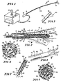
- Fig. 7 is a perspective view of an embodiment of a plurality of temperature-activated memory elements employed in the distal end of the catheter, cannula, and the like to deflect or move the distal end for steering and aiming thereof;
- Fig. 8 is an exploded view of another embodiment of the present invention;
- Fig. 9 is a longitudinal sectional view, partly broken away, showing the embodiment of Fig. 8 in its relaxed position and taken generally along section lines 9-9 of Fig. 8;
- Fig. 10 is a view, partly broken away, of the embodiment of Fig. 9 rotated 90° about its longitudinal axis;
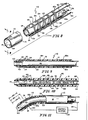
- Fig. 11 is a longitudinal sectional view, partly broken away, showing the embodiment of Fig. 8 in a deflected position;
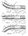
- Fig. 12 is a longitudinal sectional view of yet another embodiment of the present invention, partly broken away, showing the distal end of a catheter in a relaxed position;
- Fig. 13 is a view of the embodiment of Fig. 12, partly broken away, showing the distal end of the catheter in a partially deflected position; and
- Fig. 14 is a view of the embodiment of Fig. 12, partly broken away, showing the distal end of the catheter in a fully deflected position.
- A
catheter 10 embodying the present invention is shown generally in Fig. 1.Catheter 10 includes an elongatedtubular member 12 having aproximal end 14 and a steerable and aimabledistal end 16. In the illustrative embodiment, thetubular member 12 is formed of plastic, TEFLON, or cross-linked kynar or polyethylene. As will become apparent in the description ofcatheter 10, it is desirable thattubular member 12 be formed of a material that is flexible, that can withstand heat, and which provides electrical insulation. - As best shown in Fig. 2, the
tubular member 12 can have alumen 18 for the passage of fluid from theproximal end 14 to thedistal end 16 and vice versa. Typically, thetubular member 12 includes one or more holes oropenings 19 through which fluids are either injected into or drained from a body cavity. Some cannulae may have an opendistal end 16 for insertion and withdrawal of medical instruments. - As shown in Figs. 2 and 3, a plurality of temperature-activated
memory elements 20 are incorporated into thedistal end 16 of thetubular member 12. It may be desirable to isolate thememory elements 20 from the body cavity. The temperature-activatedmemory elements 20 preferably exhibit a memory characteristic in response to temperature changes. Theelements 20 may be wires or flat strips such as shown in Fig. 3. In the illustrative embodiment, the temperature-activatedmemory elements 20 are formed of a mechanical memory metal such as a nickel titanium alloy. While a nickel titanium alloy is desirable, other metal elements having a memory characteristic related to temperature could be used without departing from the scope of the invention. Such metal elements should have a high resistance to electric current so that heat is produced when current is passed therethrough. - As shown in Fig. 3, the
elements 20 have abody portion 22 and atip portion 24. Eachelement 20 has a first or preset shape represented by the broken lines in Fig. 3 and a second shape represented by the solid lines in Fig. 3. Illustratively, the preset shape is an arcuate shape, and the second shape is a straight shape. It will be appreciated that the preset shape could be any shape. - Each temperature-activated
memory element 20 is originally annealed into its preset shape (represented by the broken lines in Fig. 3).Memory elements 20 are cooled and straightened to their second shape (represented by the solid lines in Fig. 3) before incorporation into thedistal end 16 of thetubular member 12. When theelements 20 are again heated to a predetermined transitional temperature they return to their preset shape. By applying an opposing force to anelement 20 that has moved to assume its preset shape it can be moved to its second shape (represented by the solid lines in Fig. 3). In the illustrative embodiment, the predetermined transitional temperature is any temperature above body temperature. For example, the predetermined transitional temperature may be in the range of 100 to 150° F. - The
memory elements 20 can either be directly incorporated into thedistal end 16 of thetubular member 12 or can be carried on an electricallyinsulative core 50. As will be discussed later, eachmemory element 20 must be coupled to at least oneother memory element 20 so that when one of the memory elements is heated it applies a force to move theother memory element 20. - The
catheter 10 further includes anelectronic control system 30 for controlling current flow to vary the temperature of each temperature-activatedmemory element 20 from a position external to the body so as to deflect thedistal end 16 of thetubular member 12 in a plurality of different directions corresponding to the preset shapes of theelements 20. Thecontrol system 30 includes apower supply source 32 which may be either AC or DC. Thesystem 30 also includes acontrol device 34 which, in the illustrative embodiment, is similar to a "joystick" control, tactile membrane switch, or ball controller. It will be appreciated that various types ofcontrol devices 34 may be employed without departing from the scope of the present invention. - The power supply source 32 is coupled through
control device 34 to thetubular member 12 by cable 36 and acoupling device 38. Further, the temperature-activatedmemory elements 20 are electrically connected to thecontrol device 34 through cable 36 andcoupling 38 byelectrical wires 40 which are attached to thebody portions 22 ofmemory elements 20 byconventional means 42 such as soldering or crimping. Return orground wires 44 are attached to thetip portions 24 ofmemory elements 20 by conventional means such as soldering or crimping 46. Return orground wires 44 may be combined into asingle ground cable 48 as shown in Fig. 2. - In the embodiment illustrated in Fig. 2, the temperature-activated
memory elements 20 are carried on the exterior of thecore 50 andground wire 48 runs through the interior of thecore 50.Core 50 couples eachmemory element 20 to at least oneother memory element 20 so that when amemory element 20 moves to assume its preset shape in response to heat it applies a force to move theother memory element 20 coupled thereto. In preferred embodiments, thecore 50 is a tube formed of urethane having a wall thickness of about 0.005 inch. In other embodiments, thecore 50 may be a fiber optics bundle, electrical wire, micro- instrumentation, or any other suitable member. Other mounting arrangements could be used for incorporating thememory elements 20 into thedistal end 16 of thetubular member 12 without departing from the scope of the present invention. - In operation, the
distal end 16 of thetubular member 12 is inserted into abody cavity 60 such as a blood vessel whilememory elements 20 are straight and at a temperature below the transitional temperature. At this stage, eachmemory element 20 is in its second shape for ready insertion of thedistal end 16 into thebody cavity 60. Thetubular member 12 is pushed throughcavity 60 until it reaches a desiredbranch cavity 60.Control device 34 is manipulated to apply an electrical voltage or current to one or more of thememory elements 20. Because of the high resistance ofmemory elements 20, heat is generated. When a memory element is heated to its predetermined transitional temperature (i.e., a predetermined temperature above body temperature) thememory element 20 moves to assume its preset shape (as shown by the broken lines in Fig. 3), thereby deflecting or moving thedistal end 16 oftubular member 12 into one of the desiredbranch cavities distal end 16 is in thebranch memory element 20 to allow it to cool. While thememory element 20 is at a temperature above its predetermined transitional temperature it remains relatively stiff in its preset shape. When thememory element 20 cools to a temperature below its predetermined transitional temperature it becomes soft or pliable in its preset shape. After cooling, a voltage or current is applied to anothermemory element 20 coupled to the cooledmemory element 20 still in its preset shape. When theother memory element 20 reaches its predetermined transitional temperature, it begins to move to assume its preset shape and in doing so applies a force to thememory element 20 coupled thereto to move it to its second shape (as shown by the solid lines in Fig. 3). Thecatheter tubular member 12 can continue to be pushed through thebranch catheter 10. - As illustrated in Fig. 4, four temperature-activated
memory elements 20 may be carried on the exterior ofcore 50. In the illustrative embodiment, pairs of thememory elements 20 are shown diametrically opposed to each other so thatopposed elements 20 apply forces to each other when they are heated. Thus, thedistal end 16 may be deflected in at least four different directions by applying an electrical current or voltage to one of thememory elements 20. It will be appreciated that more or less than fourmemory elements 20 may be utilized without departing from the scope of the present invention. However, it should be noted that at least twomemory elements 20 are required. Further, it may be desirable to apply an electrical.voltage or current to more than one of thememory elements 20 simultaneously to increase the number of directions in which thedistal end 16 of thetubular member 12 may be deflected. Thecontrol system 30 may include means for regulating the application of current or voltage applied to thememory elements 20 to allow virtually an unlimited number of directions in which thedistal end 16 may be deflected for the purpose of steering thecatheter tubular member 10 through body cavities. It will be appreciated that a large number of wire memory elements could be incorporated into thedistal end 16 and a voltage or current applied to one or more of the wires to deflect thedistal end 16 in a desired direction. - Another application for a
catheter 70 embodying the present invention is shown in Figs. 5 and 6. Reference numerals from Figs. 1-4 have been applied to thecatheter 70 shown in Figs. 5 and 6 where the same or similar parts are being used.Catheter 70 includes atubular member 72 having adistal end 76. Thedistal end 76 includes a plurality of temperature-activatedmemory elements 20 of the type previously described. The same or similar control system may be employed in connection with thecatheter 70 in abody cavity 80 for the purpose of aiming thedistal end 76 at an obstruction, organ, ortissue 82 within thecavity 80. Thecatheter 70 may be anchored in thecavity 80 by aballoon 78. Once thecatheter 70 is anchored, thedistal end 76 is aimed in one of a plurality of directions to establish a course for the injection of fluid or a laser beam at the organ ortissue 82. - As shown in Fig. 6, a core 90 formed of insulative material passes through
tubular member 72.Memory elements 20 are carried on the core 90 between the core 90 and thetubular member 72. Core -90 serves to couple eachmemory element 20 to at least oneother memory element 20 in the manner and for the purpose previously described. Thehollow core 90 may include afirst tube 92 for carrying a fluid from the proximal end of thecatheter 70 to thedistal end 76. Areturn tube 94 may be included for extracting fluid. It will be appreciated that eitherpassage cavity 80.Core 90 may also include atransparent member 95 providing a lens for observing the obstruction, organ, ortissue 82 and a bundle of fiber-optic lines 96 for transmitting light or a laser beam to thedistal end 76. Thus, in the embodiment illustrated in Figs. 5 and 6,catheter 70 has adistal end 76 which is aimable in a plurality of directions in accordance with the present invention for the purpose of establishing a course for the injection of fluid, light, or a laser beam at an obstruction, organ, ortissue 82. - Another embodiment of an arrangement for the
memory elements 20 is shown in Fig. 7. Thememory element arrangement 100 includes a plurality ofmemory elements 20 coupled at theirdistal ends 24 by a thermally and electricallyinsulative ring 102. Various materials, such as plastic, may be used to construct thering 102. Ground wires from eachmemory element 20 are channeled through a commonground wire conduit 44.Ring 102 serves to couple thememory elements 20 to each other and performs a function similar tocores memory elements 20 in thedistal end catheters - Yet another embodiment of the present invention is shown in Figs. 8-11. Reference numerals from Figs. 1-4 have been applied to a
catheter 110 shown in Figs. 8-11 where the same or similar parts are being used.Catheter 110 includes atubular member 12, a pair of temperature-activatedmemory elements 20a and 20b, and acore 50 of the types described above.Memory elements 20a and 20b may be flat as shown in Figs. 8-11 or in some applications may be wires, particularly where more than two memory elements are employed. Thecatheter 110 further includes asleeve 112 for slidably coupling each memory element 20a,b to thecore member 50 so that each memory element 20a,b is permitted to slip in relation to theadjacent core member 50 when at least one of the memory elements 20a,b moves to assume its predetermined shape. Thesleeve 112 also interconnects one memory element to another memory element so that when one memory element moves in a first direction to assume its preset shape a force is applied to move the other memory element in the first direction and vice-versa. - Desirably, the
sleeve 112 is a resilient tubular jacket for embracing elastically thecore member 50 and the memory elements 20a,b to provide a slip interface therebetween. Thesleeve 112 includes an axiallyinner portion 113 for the reception of a distal end of thecore 50 and thetip portions 24 of each memory element and an axially outer portion 114 for the reception of a forward tip portion of the core. Thus, each memory element received within the sleeve 112 simultaneously is retainable in a core-guiding position as shown in Figs. 9-11 and is movable with thesleeve 112 to deflect the distal end of the core 50 to a selected position (e.g. the deflected position illustrated in Fig. 11). - The
sleeve 112 includes aninner wall 115 defining aslip chamber 116 in which each memory element is able to slip in relation to thecore member 50 during selective heating of at least one of thememory elements 20. In preferred embodiments, thesleeve 112 is formed of thin MYLAR material having a thickness of about 0.001 inch. Any other similar material that has a low coefficient of friction and is not generally susceptible to deformation under heat would be suitable. - As shown best in Figs. 8 and 9, the
core 50 includes adistal end 118 having aforward tip portion 120. Installation of thesleeve 112 operates to position theforward tip portion 24 of each memory element 20a,b in close proximity to thedistal end 118 of thecore 50. The first and second memory elements 20a,b are positioned on opposite sides of the core 50 in spaced relation as shown in Figs. 8, 9, and 11 so that thecore 50 is intermediate the two memory elements. Thus, theforward tip portion 24 of each memory element is retained in its core-guiding position bysleeve 112. In addition, the remainingbody portion 22 of each memory element is retained in its core-guiding position by means of a wrap. - The memory element retaining wrap is desirably a
continuous filament 122 as illustrated in Figs. 8-11. For example, a nylon filament having a 0.002 inch diameter would be satisfactory. Thefilament wrap 122 couples at least a segment of thebody portion 22 of each memory element 20a,b to the core 50 so that the body remaining portion segment is permitted to slip in relation to theadjacent core 50 when at least one of the memory elements 20a,b moves to assume its preset shape. Desirably, thefilament wrap 122 embraces a radially outwardly-facingsurface 124 of each of the memory elements in sufficiently tight relation to retain the memory elements in their coupled position while permitting relative slipping movement between each coupled memory element and thecore 50. As shown in Figs. 8 and 10, thecontinuous filament 122 defines a plurality of windingbunches 126 disposed along the length of the core 50 in spaced-apart relation so that each winding in a windingbunch 126 can move along the core in relation to one another in thespaces 128 therebetween during deflection or bending of thedistal end 16 of thetubular member 12. Illustratively, each spaced windingbunch 126 includes three windings as shown in Figs. 8 and 10. - In the embodiment illustrated in Figs. 8-11, the temperature-activated memory elements 20a,b are electrically connected to the control
device 34.by wire 130 of rectangular cross-section. The remainder ofrectangular wire 130 is mounted along theside edge 132 of the remainingportion 22 of eachmemory element 20. Return orground wire 134 is also of rectangular cross-section and mounted along anotherside edge 136 of each memory element at a proximal end of the remainingbody portion 22 of the memory element. Other suitable electrical coupling means are usable to couple the memory elements of the embodiment of Figs. 8-11 to thecontrol device 34 without departing from the scope of the present invention. - In operation, the
sleeve 112 included in the embodiment of Figs. 8-11 provides numerous advantages. One advantage is that maneuverability of thecatheter 110 is improved due to slippage of each memory element 20a,b relative tocore 50 in theslip chamber 116 defined by thesleeve 112. A certain amount of slippage is desirable to allow relative movement of thememory elements 20 and the core 50 to improve the flexibility of the catheter. As shown best in Fig. 11, movement of the first memory element 20a to assume its predetermined position causes theforward tip portion 24 .of the first memory element 20a to move along the exterior surface of the core 50 toward theforward tip portion 120 of thecore 50 and theforward tip portion 24 of thesecond memory element 20b to move along the exterior surface of the core 50 away from theforward tip portion 120 of thecore 50. In other words, thefirst memory element 20b is arcuately shaped when the memory element 20a moves to assume its predetermined shape and vice versa. In particular, the arc defined by the memory element 20a is smaller than the arc defined by the equidistantly spaced-apartmemory element 20b as shown in Fig. 11. The slippage ofmemory elements 20a and 20b relative to theforward tip portion 120 ofcore 50 is shown by the arrows in Fig. 11.Arrow 140 represents the positions of thetips 24 before deflection and arrows 142 and 144 represent the positions of thetips 24 ofelements 20b and 20a respectively when the catheter is deflected. - Still another embodiment of the present invention is shown in Figs. 12-14. Reference numerals from Figs. 1-4 and 8-11 have been applied to a
catheter 210 as shown in Figs. 12-14 where the same or similar parts are being used.Catheter 210 includes atubular member 12, a temperature-activatedmemory element 20, and asleeve 112 of the types described above. - An electrically insulative
hollow core member 240 is provided in the interior oftubular member 12 for receiving medical instruments, fiber optics lines, fluid-conducting tubes, or other medical or optical tools.Core member 240 is desirably made of plastics material such as urethane, TEFLON, KYNAR, or polyethylene and has a wall thickness of .005 - .010 inch (1.27 - 2.54 mm). In contrast to the core members illustrated in connection with the embodiments of Figs. 1-11 that are generally straight in their relaxed positions,core member 240 is preformed using known techniques to assume a curved shape in its relaxed position as shown in Fig. 12. - The
catheter 210 further includes aspring 242 positioned on the exterior ofcurved core member 240 in diametrically opposed relation tomemory element 20. Thespring 242 is desirably made of stainless steel or plastics material and has a thickness of .010 inch (2.54 mm). Thespring 242 is also preformed using known techniques to assume a curved shape. As shown in Fig. 12, the radius of curvature of preformedspring 242 is less than the radius of curvature ofcurved core member 240. -
Spring 242 effectively serves as a resilient memory element and cooperates withcore 240 to loadmemory element 20 with a force that bendsmemory element 20 to an initial shape illustrated in Fig. 12. The spring constant ofspring 242 is selected to cause,spring 242 to bend the distal end of the catheter in one direction as shown in Fig. 12 and also yield under loading provided by theheated memory element 20 to permit the distal end of the catheter to bend in an opposite second direction as shown in Figs. 13 and 14. -
Sleeve 112 slidablycouples memory element 20 and preformedspring 242 tocurved core member 240 so that thememory element 20 andspring 242 are permitted to slip in relation to theadjacent core member 240 when either of thememory element 20 and thespring 242 move to assume its preset shape. Thesleeve 112 also interconnectsmemory element 20 tospring 242 so that when thememory element 20 moves in afirst direction 254 to assume its preset shape a force is applied to move thespring 242 in thefirst direction 254 and vice versa. - In the diagrammatic embodiment illustrated in Figs. 12-14, the temperature-activated
memory element 20 is electrically connected to acontrol device 234 and apower supply 244 bywires Control device 234 includes switch means 248 and power control means 250. Switch means 248 is operable to decouple thepower supply 244 and thememory element 20 to prevent heating ofmemory element 20. Power control means 250 is operable to vary the electrical power provided tomemory element 20, thereby regulating the amount of heat applied tomemory element 20. Illustratively, power control means 250 is a rheostat. It will be appreciated by those skilled in the art that the manner of controlling the temperature ofmemory element 20 can be accomplished using a variety of control systems other than the illustrated system without departing from the scope of the present invention. - One exemplary operation sequence of
catheter 210 is illustrated in Figs. 12-14. In particular, the relaxed state of the distal end oftubular member 12 is shown in Fig. 12. The preset curved shapes ofcore member 240 andspring 242 act to bend the distal end oftubular member 12 indirection 252 as shown in Fig. 12. At this stage, switch means 248 is in its open circuit position, preventing current generated bypower supply 244 from being applied to heat thememory element 20. Thus, the relativelycool memory element 20 is also bent indirection 252 due to the interconnection withcore member 240 andspring 242 established bysleeve 112 andtubular member 12. Such bending resulting from the preset curved shapes ofcore member 240 andspring 242 effectively defines an "initial position" of thememory element 20 and the distalend tubular member 12. - Steering and aiming of
catheter 210 is accomplished by operation ofcontrol device 234 in the following manner. Once switch means 248 is moved to its closed circuit position shown in Figs. 13 and 14, the operator can control the heating and cooling of the temperature-activatedmemory element 20 by using power control means 250. - Movement of power control means 250 to a first setting illustratively depicted in Fig. 13 causes a sufficient amount of power to be applied to
memory element 20 so that thememory element 20 is heated and moves indirection 254 away from its initial curved shape to assume a substantially straight shape. The steering force generated by such movement is transmitted tocore member 240 andspring 242 in part viasleeve 112. This steering force is sufficient to overcome opposing "return" forces generated bycore member 240 andspring 242. - Continued movement of power control means 250 to another power setting illustratively depicted in Fig. 14 causes still more power to be applied to
memory element 20. This heatsmemory element 20 to a higher "predetermined" temperature, causing thememory element 20 to continue to move indirection 254 to assume a "predetermined" curved shape. - Return of the
catheter 210 to its initial relaxed state shown in Fig. 12 is easily accomplished by usingcontrol device 234 to lessen the amount of power applied tomemory element 20. This step allowsmemory element 20 to cool, thereby permittingpreset core member 240 andspring 242 to cooperate to exert a return force on the distal end of thetubular member 12 andmemory element 20. Such a return force acts indirection 252 in the absence of a steering force generated bymemory element 20, thereby causingcatheter 210 to be returned to its relaxed state. - It will be appreciated that a plurality of pairs of temperature-activated
memory elements 20 and springs 242 could be positioned in the distal end of the catheter to provide a great deal of flexability in steering and airming the catheter. However, it will be understood that it is possible to steer and aim a catheter provided with only a single temperature-activatedmemory element 20 andreturn spring 242 in a multiplicity of radial directions by rotating the catheter about its central longitudinal axis during heating ofmemory element 20 usingcontrol device 234. - While illustrative embodiments and uses of catheters, cannulae, and the like embodying the present invention have been shown and described, it will be appreciated that various modifications may be made to the illustrative embodiments without departing from the scope of the present invention.
Claims (30)
Applications Claiming Priority (2)
| Application Number | Priority Date | Filing Date | Title |
|---|---|---|---|
| US870926 | 1986-06-05 | ||
| US06/870,926 US4758222A (en) | 1985-05-03 | 1986-06-05 | Steerable and aimable catheter |
Publications (3)
| Publication Number | Publication Date |
|---|---|
| EP0251437A2 true EP0251437A2 (en) | 1988-01-07 |
| EP0251437A3 EP0251437A3 (en) | 1988-11-23 |
| EP0251437B1 EP0251437B1 (en) | 1992-08-19 |
Family
ID=25356350
Family Applications (1)
| Application Number | Title | Priority Date | Filing Date |
|---|---|---|---|
| EP87303577A Revoked EP0251437B1 (en) | 1986-06-05 | 1987-04-23 | Steerable and aimable catheter |
Country Status (5)
| Country | Link |
|---|---|
| US (1) | US4758222A (en) |
| EP (1) | EP0251437B1 (en) |
| JP (1) | JPS62290471A (en) |
| CA (1) | CA1263832A (en) |
| DE (1) | DE3781214T2 (en) |
Cited By (4)
| Publication number | Priority date | Publication date | Assignee | Title |
|---|---|---|---|---|
| EP0310295A2 (en) * | 1987-10-02 | 1989-04-05 | Catheter Research, Inc. | Maneuverable distal apparatus |
| EP0421368A1 (en) * | 1989-10-05 | 1991-04-10 | Nivarox-FAR S.A. | Device for rehabilitation of a body member |
| EP0631792A1 (en) * | 1988-12-23 | 1995-01-04 | Advanced Cardiovascular Systems, Inc. | Steerable dilatation catheter |
| GB2306111A (en) * | 1995-10-14 | 1997-04-30 | William Barrie Hart | Expandable hydraulic oversleeve for advancing an endoscope into a body cavity |
Families Citing this family (125)
| Publication number | Priority date | Publication date | Assignee | Title |
|---|---|---|---|---|
| US5114402A (en) * | 1983-10-31 | 1992-05-19 | Catheter Research, Inc. | Spring-biased tip assembly |
| US5055101A (en) * | 1983-10-31 | 1991-10-08 | Catheter Research, Inc. | Variable shape guide apparatus |
| US5090956A (en) * | 1983-10-31 | 1992-02-25 | Catheter Research, Inc. | Catheter with memory element-controlled steering |
| US5025799A (en) * | 1987-05-13 | 1991-06-25 | Wilson Bruce C | Steerable memory alloy guide wires |
| US5211183A (en) * | 1987-05-13 | 1993-05-18 | Wilson Bruce C | Steerable memory alloy guide wires |
| JPS6480367A (en) * | 1987-09-21 | 1989-03-27 | Terumo Corp | Member for correcting ureter |
| JPH0346723Y2 (en) * | 1987-12-19 | 1991-10-03 | ||
| JPH01164349A (en) * | 1987-12-19 | 1989-06-28 | Kato Hatsujo Kaisha Ltd | Apparatus for bending leading end part of medical tube |
| US4984581A (en) * | 1988-10-12 | 1991-01-15 | Flexmedics Corporation | Flexible guide having two-way shape memory alloy |
| US5037391A (en) * | 1989-01-09 | 1991-08-06 | Pilot Cardiovascular Systems, Inc. | Steerable angioplasty device |
| US5203772A (en) * | 1989-01-09 | 1993-04-20 | Pilot Cardiovascular Systems, Inc. | Steerable medical device |
| US4998916A (en) * | 1989-01-09 | 1991-03-12 | Hammerslag Julius G | Steerable medical device |
| US5108368A (en) * | 1990-01-04 | 1992-04-28 | Pilot Cardiovascular System, Inc. | Steerable medical device |
| US5480382A (en) * | 1989-01-09 | 1996-01-02 | Pilot Cardiovascular Systems, Inc. | Steerable medical device |
| US5308324A (en) * | 1989-01-09 | 1994-05-03 | Pilot Cardiovascular Systems, Inc. | Steerable medical device |
| US5120308A (en) * | 1989-05-03 | 1992-06-09 | Progressive Angioplasty Systems, Inc. | Catheter with high tactile guide wire |
| US4934340A (en) * | 1989-06-08 | 1990-06-19 | Hemo Laser Corporation | Device for guiding medical catheters and scopes |
| US5273535A (en) * | 1991-11-08 | 1993-12-28 | Ep Technologies, Inc. | Catheter with electrode tip having asymmetric left and right curve configurations |
| US5891088A (en) * | 1990-02-02 | 1999-04-06 | Ep Technologies, Inc. | Catheter steering assembly providing asymmetric left and right curve configurations |
| US5358478A (en) * | 1990-02-02 | 1994-10-25 | Ep Technologies, Inc. | Catheter steering assembly providing asymmetric left and right curve configurations |
| JPH06504209A (en) * | 1990-02-14 | 1994-05-19 | アデア エドウィン エル | Endotracheal tube insertion assist device |
| US5109830A (en) * | 1990-04-10 | 1992-05-05 | Candela Laser Corporation | Apparatus for navigation of body cavities |
| US5135517A (en) * | 1990-07-19 | 1992-08-04 | Catheter Research, Inc. | Expandable tube-positioning apparatus |
| US5167624A (en) * | 1990-11-09 | 1992-12-01 | Catheter Research, Inc. | Embolus delivery system and method |
| US5133731A (en) * | 1990-11-09 | 1992-07-28 | Catheter Research, Inc. | Embolus supply system and method |
| US5123421A (en) * | 1991-01-16 | 1992-06-23 | C. R. Bard, Inc. | Liquid activated steerable catheter guidewire |
| US5108420A (en) * | 1991-02-01 | 1992-04-28 | Temple University | Aperture occlusion device |
| US5231989A (en) * | 1991-02-15 | 1993-08-03 | Raychem Corporation | Steerable cannula |
| US5217003A (en) * | 1991-03-18 | 1993-06-08 | Wilk Peter J | Automated surgical system and apparatus |
| US5217453A (en) * | 1991-03-18 | 1993-06-08 | Wilk Peter J | Automated surgical system and apparatus |
| US5131380A (en) * | 1991-06-13 | 1992-07-21 | Heller Richard M | Softwall medical tube with fiberoptic light conductor therein and method of use |
| US5238005A (en) * | 1991-11-18 | 1993-08-24 | Intelliwire, Inc. | Steerable catheter guidewire |
| US5396879A (en) * | 1992-04-09 | 1995-03-14 | Wilk; Peter J. | Elongate medical instrument with distal end orientation control |
| US5389072A (en) * | 1992-06-05 | 1995-02-14 | Mircor Biomedical, Inc. | Mechanism for manipulating a tool and flexible elongate device using the same |
| US5324284A (en) * | 1992-06-05 | 1994-06-28 | Cardiac Pathways, Inc. | Endocardial mapping and ablation system utilizing a separately controlled ablation catheter and method |
| US5325845A (en) * | 1992-06-08 | 1994-07-05 | Adair Edwin Lloyd | Steerable sheath for use with selected removable optical catheter |
| US5399164A (en) * | 1992-11-02 | 1995-03-21 | Catheter Imaging Systems | Catheter having a multiple durometer |
| US5857996A (en) | 1992-07-06 | 1999-01-12 | Catheter Imaging Systems | Method of epidermal surgery |
| US5628719A (en) * | 1992-11-25 | 1997-05-13 | Scimed Life Systems, Inc. | In vivo mechanical energy source and perfusion pump |
| EP0600413A3 (en) * | 1992-11-30 | 1995-04-05 | Neuro Navigational Corp | Neuro endoscope for shunt. |
| US5383852A (en) * | 1992-12-04 | 1995-01-24 | C. R. Bard, Inc. | Catheter with independent proximal and distal control |
| US5378234A (en) * | 1993-03-15 | 1995-01-03 | Pilot Cardiovascular Systems, Inc. | Coil polymer composite |
| US5476495A (en) * | 1993-03-16 | 1995-12-19 | Ep Technologies, Inc. | Cardiac mapping and ablation systems |
| US6233491B1 (en) | 1993-03-16 | 2001-05-15 | Ep Technologies, Inc. | Cardiac mapping and ablation systems |
| US5334207A (en) * | 1993-03-25 | 1994-08-02 | Allen E. Coles | Laser angioplasty device with magnetic direction control |
| US5409460A (en) * | 1993-04-15 | 1995-04-25 | The Beta Group Inc. | Intra-luminal expander assembly |
| US5531685A (en) * | 1993-06-11 | 1996-07-02 | Catheter Research, Inc. | Steerable variable stiffness device |
| US5334168A (en) * | 1993-06-11 | 1994-08-02 | Catheter Research, Inc. | Variable shape guide apparatus |
| US5456245A (en) * | 1993-09-20 | 1995-10-10 | Sofamor Danek Properties, Inc. | Flexible endoscope probe and method of manufacture |
| US5464404A (en) * | 1993-09-20 | 1995-11-07 | Abela Laser Systems, Inc. | Cardiac ablation catheters and method |
| US5782824A (en) * | 1993-09-20 | 1998-07-21 | Abela Laser Systems, Inc. | Cardiac catheter anchoring |
| US5651785A (en) * | 1993-09-20 | 1997-07-29 | Abela Laser Systems, Inc. | Optical fiber catheter and method |
| US5651786A (en) * | 1993-09-20 | 1997-07-29 | Abela Laser Systems, Inc. | Mapping catheter and method |
| US5577992A (en) * | 1993-10-05 | 1996-11-26 | Asahi Kogaku Kogyo Kabushiki Kaisha | Bendable portion of endoscope |
| US5881727A (en) * | 1993-10-14 | 1999-03-16 | Ep Technologies, Inc. | Integrated cardiac mapping and ablation probe |
| US5718861A (en) * | 1993-12-20 | 1998-02-17 | C. R. Bard, Incorporated | Method of forming intra-aortic balloon catheters |
| DE4408730A1 (en) * | 1994-03-15 | 1995-09-21 | Daum Gmbh | Controllable instrument channel for min invasive surgery |
| DE4417637A1 (en) * | 1994-05-19 | 1995-11-23 | Rudolf Dr Med Bertagnoli | Instrument for the percutaneous treatment of tissue parts |
| US5492131A (en) * | 1994-09-06 | 1996-02-20 | Guided Medical Systems, Inc. | Servo-catheter |
| US6007531A (en) * | 1995-11-21 | 1999-12-28 | Catheter Imaging Systems, Inc. | Steerable catheter having disposable module and sterilizable handle and method of connecting same |
| USD398986S (en) | 1996-01-16 | 1998-09-29 | Catheter Imaging Systems, Inc. | Handle interface for steerable catheter |
| US5860953A (en) * | 1995-11-21 | 1999-01-19 | Catheter Imaging Systems, Inc. | Steerable catheter having disposable module and sterilizable handle and method of connecting same |
| USD405881S (en) | 1996-01-16 | 1999-02-16 | Catheter Imaging Systems, Inc. | Handle for steerable catheter |
| US6068623A (en) | 1997-03-06 | 2000-05-30 | Percusurge, Inc. | Hollow medical wires and methods of constructing same |
| US5941249A (en) * | 1996-09-05 | 1999-08-24 | Maynard; Ronald S. | Distributed activator for a two-dimensional shape memory alloy |
| US6072154A (en) | 1996-09-05 | 2000-06-06 | Medtronic, Inc. | Selectively activated shape memory device |
| US6133547A (en) * | 1996-09-05 | 2000-10-17 | Medtronic, Inc. | Distributed activator for a two-dimensional shape memory alloy |
| US5810790A (en) * | 1996-11-19 | 1998-09-22 | Ebling; Wendell V. | Catheter with viewing system and port connector |
| WO2001008737A1 (en) * | 1999-07-29 | 2001-02-08 | Scope Medical, Inc. | Steerable medical device |
| US6579279B1 (en) | 1999-09-24 | 2003-06-17 | Omnisonics Medical Technologies, Inc. | Steerable catheter device |
| US20040097996A1 (en) | 1999-10-05 | 2004-05-20 | Omnisonics Medical Technologies, Inc. | Apparatus and method of removing occlusions using an ultrasonic medical device operating in a transverse mode |
| US6572536B1 (en) | 1999-11-05 | 2003-06-03 | Visionary Biomedical, Inc. | Autoclavable flexible fiberscope |
| US6533752B1 (en) | 2000-01-05 | 2003-03-18 | Thomas C Waram | Variable shape guide apparatus |
| US7555333B2 (en) | 2000-06-19 | 2009-06-30 | University Of Washington | Integrated optical scanning image acquisition and display |
| SE0002515D0 (en) | 2000-06-30 | 2000-06-30 | Pacesetter Ab | Locator device |
| DE10034105C1 (en) * | 2000-07-13 | 2002-04-04 | Karlsruhe Forschzent | Spring tension effector for minimal invasive surgery has pivot device for instrument head controlled via parallel spring band strips coupled to pivot setting mechanism |
| US6906883B2 (en) * | 2000-09-14 | 2005-06-14 | Samsung Electronics Ltd., Co. | Servo defect management scheme in hard disk drives |
| US6724553B2 (en) | 2001-03-26 | 2004-04-20 | Samsung Electronics Co., Ltd. | Method and apparatus for generating the optimum read timing for read and write offset of a magneto resistive head |
| US6652491B1 (en) | 2001-05-03 | 2003-11-25 | Catheter Research, Inc. | Steerable stylet |
| KR100468764B1 (en) * | 2001-09-13 | 2005-01-29 | 삼성전자주식회사 | Method and apparatus for providing positional information on a disk |
| US6791780B2 (en) | 2001-10-15 | 2004-09-14 | Samsung Electronics Co., Inc. | Method and apparatus for providing write current optimization |
| US7035031B2 (en) * | 2001-11-26 | 2006-04-25 | Samsung Electronics Co., Ltd. | Installation of heater into hard disk drive to improve reliability and performance at low temperature |
| US7818048B2 (en) * | 2003-06-02 | 2010-10-19 | Biosense Webster, Inc. | Catheter and method for mapping a pulmonary vein |
| US7291127B2 (en) | 2003-07-28 | 2007-11-06 | Boston Scientific Scimed, Inc. | Variable manipulative strength catheter |
| US7901348B2 (en) | 2003-12-12 | 2011-03-08 | University Of Washington | Catheterscope 3D guidance and interface system |
| US7794414B2 (en) | 2004-02-09 | 2010-09-14 | Emigrant Bank, N.A. | Apparatus and method for an ultrasonic medical device operating in torsional and transverse modes |
| WO2005115117A2 (en) * | 2004-05-24 | 2005-12-08 | The Trustees Of Columbia University In The City Of New York | Steerable devices |
| US7530948B2 (en) | 2005-02-28 | 2009-05-12 | University Of Washington | Tethered capsule endoscope for Barrett's Esophagus screening |
| US20060270975A1 (en) * | 2005-05-31 | 2006-11-30 | Prorhythm, Inc. | Steerable catheter |
| US20060270976A1 (en) * | 2005-05-31 | 2006-11-30 | Prorhythm, Inc. | Steerable catheter |
| JP2009516568A (en) * | 2005-11-23 | 2009-04-23 | ユニヴァーシティ オブ ワシントン | Scanning a beam with variable sequential framing using interrupted scanning resonances |
| JP2009528128A (en) | 2006-03-03 | 2009-08-06 | ユニヴァーシティ オブ ワシントン | Multi-clad optical fiber scanner |
| US8551019B1 (en) | 2006-09-06 | 2013-10-08 | Pacesetter, Inc. | Variable stiffness guide wire |
| US8096943B2 (en) * | 2006-12-04 | 2012-01-17 | University Of Washington Through Its Center For Commercialization | Flexible endoscope tip bending mechanism using optical fiber as compression member |
| US7879004B2 (en) * | 2006-12-13 | 2011-02-01 | University Of Washington | Catheter tip displacement mechanism |
| US20080221388A1 (en) * | 2007-03-09 | 2008-09-11 | University Of Washington | Side viewing optical fiber endoscope |
| US8840566B2 (en) | 2007-04-02 | 2014-09-23 | University Of Washington | Catheter with imaging capability acts as guidewire for cannula tools |
| WO2008137710A1 (en) | 2007-05-03 | 2008-11-13 | University Of Washington | High resolution optical coherence tomography based imaging for intraluminal and interstitial use implemented with a reduced form factor |
| US20090076417A1 (en) * | 2007-08-08 | 2009-03-19 | Gregory Allen Jones | Glide Clip |
| WO2009058198A1 (en) | 2007-11-02 | 2009-05-07 | Rex Medical, L.P. | Method of inserting a vein filter |
| US20090208143A1 (en) * | 2008-02-19 | 2009-08-20 | University Of Washington | Efficient automated urothelial imaging using an endoscope with tip bending |
| US8684962B2 (en) | 2008-03-27 | 2014-04-01 | St. Jude Medical, Atrial Fibrillation Division, Inc. | Robotic catheter device cartridge |
| WO2009120982A2 (en) | 2008-03-27 | 2009-10-01 | St. Jude Medical, Atrial Fibrillation Division, Inc. | Robotic catheter system with dynamic response |
| US9161817B2 (en) | 2008-03-27 | 2015-10-20 | St. Jude Medical, Atrial Fibrillation Division, Inc. | Robotic catheter system |
| US8343096B2 (en) | 2008-03-27 | 2013-01-01 | St. Jude Medical, Atrial Fibrillation Division, Inc. | Robotic catheter system |
| US8317744B2 (en) | 2008-03-27 | 2012-11-27 | St. Jude Medical, Atrial Fibrillation Division, Inc. | Robotic catheter manipulator assembly |
| US20090248042A1 (en) * | 2008-03-27 | 2009-10-01 | Kirschenman Mark B | Model catheter input device |
| US9241768B2 (en) | 2008-03-27 | 2016-01-26 | St. Jude Medical, Atrial Fibrillation Division, Inc. | Intelligent input device controller for a robotic catheter system |
| US8641663B2 (en) | 2008-03-27 | 2014-02-04 | St. Jude Medical, Atrial Fibrillation Division, Inc. | Robotic catheter system input device |
| US20100100055A1 (en) * | 2008-05-22 | 2010-04-22 | Td.Jam Medical Technologies , Llc | Devices for Superficial Femoral Artery Intervention |
| ES2561592T3 (en) * | 2008-09-26 | 2016-02-29 | Pixium Vision Sa | Electrode matrix and method for manufacturing |
| US20100274088A1 (en) * | 2009-04-23 | 2010-10-28 | Carl Frederic West | Flexible Medical Instrument |
| US9439736B2 (en) | 2009-07-22 | 2016-09-13 | St. Jude Medical, Atrial Fibrillation Division, Inc. | System and method for controlling a remote medical device guidance system in three-dimensions using gestures |
| US9330497B2 (en) | 2011-08-12 | 2016-05-03 | St. Jude Medical, Atrial Fibrillation Division, Inc. | User interface devices for electrophysiology lab diagnostic and therapeutic equipment |
| EP2542296A4 (en) | 2010-03-31 | 2014-11-26 | St Jude Medical Atrial Fibrill | Intuitive user interface control for remote catheter navigation and 3d mapping and visualization systems |
| US9308350B2 (en) | 2011-03-28 | 2016-04-12 | North Carolina State University | Active catheter device and associated system and method |
| US8419720B1 (en) | 2012-02-07 | 2013-04-16 | National Advanced Endoscopy Devices, Incorporated | Flexible laparoscopic device |
| US9243726B2 (en) | 2012-10-03 | 2016-01-26 | Aarne H. Reid | Vacuum insulated structure with end fitting and method of making same |
| CN106029011B (en) | 2013-12-20 | 2019-12-17 | 微仙美国有限公司 | Equipment conveying system |
| US11628009B2 (en) | 2014-12-17 | 2023-04-18 | Biosense Webster (Israel) Ltd. | EP catheter with trained support member, and related methods |
| US10497908B2 (en) | 2015-08-24 | 2019-12-03 | Concept Group, Llc | Sealed packages for electronic and energy storage devices |
| WO2018093781A1 (en) | 2016-11-15 | 2018-05-24 | Reid Aarne H | Enhanced vacuum-insulated articles with microporous insulation |
| WO2018093773A1 (en) | 2016-11-15 | 2018-05-24 | Reid Aarne H | Multiply-insulated assemblies |
| US11320086B2 (en) | 2017-08-25 | 2022-05-03 | Concept Group Llc | Multiple geometry and multiple material insulated components |
| US20220134056A1 (en) * | 2019-02-27 | 2022-05-05 | Concept Group Llc | Vacuum-insulated medical devices |
Citations (4)
| Publication number | Priority date | Publication date | Assignee | Title |
|---|---|---|---|---|
| US3773034A (en) * | 1971-11-24 | 1973-11-20 | Itt Research Institute | Steerable catheter |
| US3890977A (en) * | 1974-03-01 | 1975-06-24 | Bruce C Wilson | Kinetic memory electrodes, catheters and cannulae |
| US4176662A (en) * | 1977-06-17 | 1979-12-04 | The United States Of America As Represented By The Administrator Of The National Aeronautics And Space Administration | Apparatus for endoscopic examination |
| US4543090A (en) * | 1983-10-31 | 1985-09-24 | Mccoy William C | Steerable and aimable catheter |
Family Cites Families (8)
| Publication number | Priority date | Publication date | Assignee | Title |
|---|---|---|---|---|
| US3043309A (en) * | 1959-09-29 | 1962-07-10 | Avco Corp | Method of performing intestinal intubation |
| DE1189316B (en) * | 1963-09-24 | 1965-03-18 | Auto Union Gmbh | Device for lubricating the engine of internal combustion engines, preferably two-stroke internal combustion engines |
| US3605725A (en) * | 1968-08-07 | 1971-09-20 | Medi Tech Inc | Controlled motion devices |
| SE336642B (en) * | 1969-10-28 | 1971-07-12 | Astra Meditec Ab | |
| US4146019A (en) * | 1976-09-30 | 1979-03-27 | University Of Southern California | Multichannel endoscope |
| US4456017A (en) * | 1982-11-22 | 1984-06-26 | Cordis Corporation | Coil spring guide with deflectable tip |
| US4601705A (en) * | 1983-10-31 | 1986-07-22 | Mccoy William C | Steerable and aimable catheter |
| US4586923A (en) * | 1984-06-25 | 1986-05-06 | Cordis Corporation | Curving tip catheter |
-
1986
- 1986-06-05 US US06/870,926 patent/US4758222A/en not_active Expired - Lifetime
-
1987
- 1987-03-24 CA CA000532854A patent/CA1263832A/en not_active Expired
- 1987-04-23 DE DE8787303577T patent/DE3781214T2/en not_active Revoked
- 1987-04-23 EP EP87303577A patent/EP0251437B1/en not_active Revoked
- 1987-06-04 JP JP62139073A patent/JPS62290471A/en active Granted
Patent Citations (4)
| Publication number | Priority date | Publication date | Assignee | Title |
|---|---|---|---|---|
| US3773034A (en) * | 1971-11-24 | 1973-11-20 | Itt Research Institute | Steerable catheter |
| US3890977A (en) * | 1974-03-01 | 1975-06-24 | Bruce C Wilson | Kinetic memory electrodes, catheters and cannulae |
| US4176662A (en) * | 1977-06-17 | 1979-12-04 | The United States Of America As Represented By The Administrator Of The National Aeronautics And Space Administration | Apparatus for endoscopic examination |
| US4543090A (en) * | 1983-10-31 | 1985-09-24 | Mccoy William C | Steerable and aimable catheter |
Cited By (6)
| Publication number | Priority date | Publication date | Assignee | Title |
|---|---|---|---|---|
| EP0310295A2 (en) * | 1987-10-02 | 1989-04-05 | Catheter Research, Inc. | Maneuverable distal apparatus |
| EP0310295A3 (en) * | 1987-10-02 | 1990-09-19 | William C. Mccoy | Maneuverable distal apparatus |
| EP0631792A1 (en) * | 1988-12-23 | 1995-01-04 | Advanced Cardiovascular Systems, Inc. | Steerable dilatation catheter |
| EP0421368A1 (en) * | 1989-10-05 | 1991-04-10 | Nivarox-FAR S.A. | Device for rehabilitation of a body member |
| FR2652738A1 (en) * | 1989-10-05 | 1991-04-12 | Nivarox Sa | DEVICE FOR THE REHABILITATION OF A MEMBER. |
| GB2306111A (en) * | 1995-10-14 | 1997-04-30 | William Barrie Hart | Expandable hydraulic oversleeve for advancing an endoscope into a body cavity |
Also Published As
| Publication number | Publication date |
|---|---|
| DE3781214D1 (en) | 1992-09-24 |
| JPH0354593B2 (en) | 1991-08-20 |
| DE3781214T2 (en) | 1993-02-11 |
| US4758222A (en) | 1988-07-19 |
| EP0251437A3 (en) | 1988-11-23 |
| EP0251437B1 (en) | 1992-08-19 |
| CA1263832A (en) | 1989-12-12 |
| JPS62290471A (en) | 1987-12-17 |
Similar Documents
| Publication | Publication Date | Title |
|---|---|---|
| US4758222A (en) | Steerable and aimable catheter | |
| US4601705A (en) | Steerable and aimable catheter | |
| US5090956A (en) | Catheter with memory element-controlled steering | |
| US5114402A (en) | Spring-biased tip assembly | |
| US5055101A (en) | Variable shape guide apparatus | |
| US4944727A (en) | Variable shape guide apparatus | |
| US4543090A (en) | Steerable and aimable catheter | |
| US5334168A (en) | Variable shape guide apparatus | |
| US5279559A (en) | Remote steering system for medical catheter | |
| US5108368A (en) | Steerable medical device | |
| EP0452402B1 (en) | Steerable medical device | |
| EP1977781B1 (en) | Defined deflection structure | |
| US4934340A (en) | Device for guiding medical catheters and scopes | |
| US7785252B2 (en) | Articulating sheath for flexible instruments | |
| US4742817A (en) | Endoscopic apparatus having a bendable insertion section | |
| JPH05212119A (en) | Flexible slender apparatus having operable remote end and apparatus and method for using the same | |
| US5403297A (en) | Elongate device having steerable distal extremity and proximal bend and method | |
| JPH04319365A (en) | Bending device for flexible tube | |
| EP0330712B1 (en) | System for controlling shape and direction of a catheter,cannula,electrode,endoscope or similar article | |
| JPH05184528A (en) | Bending mechanism of flexible tube | |
| JPH0386142A (en) | Deflection operation device for tubular insertion tool | |
| JPH0386143A (en) | Deflection operating device for tubular insertion tool |
Legal Events
| Date | Code | Title | Description |
|---|---|---|---|
| PUAI | Public reference made under article 153(3) epc to a published international application that has entered the european phase |
Free format text: ORIGINAL CODE: 0009012 |
|
| AK | Designated contracting states |
Kind code of ref document: A2 Designated state(s): BE CH DE FR GB LI NL SE |
|
| PUAL | Search report despatched |
Free format text: ORIGINAL CODE: 0009013 |
|
| AK | Designated contracting states |
Kind code of ref document: A3 Designated state(s): BE CH DE FR GB LI NL SE |
|
| 17P | Request for examination filed |
Effective date: 19890119 |
|
| 17Q | First examination report despatched |
Effective date: 19900606 |
|
| RAP1 | Party data changed (applicant data changed or rights of an application transferred) |
Owner name: CATHETER RESEARCH, INC. |
|
| GRAA | (expected) grant |
Free format text: ORIGINAL CODE: 0009210 |
|
| AK | Designated contracting states |
Kind code of ref document: B1 Designated state(s): BE CH DE FR GB LI NL SE |
|
| PG25 | Lapsed in a contracting state [announced via postgrant information from national office to epo] |
Ref country code: SE Free format text: LAPSE BECAUSE OF FAILURE TO SUBMIT A TRANSLATION OF THE DESCRIPTION OR TO PAY THE FEE WITHIN THE PRESCRIBED TIME-LIMIT Effective date: 19920819 Ref country code: NL Effective date: 19920819 Ref country code: BE Effective date: 19920819 |
|
| REF | Corresponds to: |
Ref document number: 3781214 Country of ref document: DE Date of ref document: 19920924 |
|
| REG | Reference to a national code |
Ref country code: CH Ref legal event code: PL |
|
| ET | Fr: translation filed | ||
| NLV1 | Nl: lapsed or annulled due to failure to fulfill the requirements of art. 29p and 29m of the patents act | ||
| PGFP | Annual fee paid to national office [announced via postgrant information from national office to epo] |
Ref country code: FR Payment date: 19930330 Year of fee payment: 7 |
|
| PG25 | Lapsed in a contracting state [announced via postgrant information from national office to epo] |
Ref country code: GB Effective date: 19930423 |
|
| PG25 | Lapsed in a contracting state [announced via postgrant information from national office to epo] |
Ref country code: LI Free format text: LAPSE BECAUSE OF NON-PAYMENT OF DUE FEES Effective date: 19930430 Ref country code: CH Free format text: LAPSE BECAUSE OF NON-PAYMENT OF DUE FEES Effective date: 19930430 |
|
| PLBI | Opposition filed |
Free format text: ORIGINAL CODE: 0009260 |
|
| PGFP | Annual fee paid to national office [announced via postgrant information from national office to epo] |
Ref country code: DE Payment date: 19930607 Year of fee payment: 7 |
|
| 26 | Opposition filed |
Opponent name: PROF. DR. ROLAND SCHMIEDL Effective date: 19930519 |
|
| GBPC | Gb: european patent ceased through non-payment of renewal fee |
Effective date: 19930423 |
|
| RDAG | Patent revoked |
Free format text: ORIGINAL CODE: 0009271 |
|
| STAA | Information on the status of an ep patent application or granted ep patent |
Free format text: STATUS: PATENT REVOKED |
|
| REG | Reference to a national code |
Ref country code: CH Ref legal event code: PL |
|
| 27W | Patent revoked |
Effective date: 19940604 |