EP0249338A2 - Retroperfusion catheter - Google Patents
Retroperfusion catheter Download PDFInfo
- Publication number
- EP0249338A2 EP0249338A2 EP87304198A EP87304198A EP0249338A2 EP 0249338 A2 EP0249338 A2 EP 0249338A2 EP 87304198 A EP87304198 A EP 87304198A EP 87304198 A EP87304198 A EP 87304198A EP 0249338 A2 EP0249338 A2 EP 0249338A2
- Authority
- EP
- European Patent Office
- Prior art keywords
- catheter
- retroperfusion
- balloon
- lumen
- distal
- Prior art date
- Legal status (The legal status is an assumption and is not a legal conclusion. Google has not performed a legal analysis and makes no representation as to the accuracy of the status listed.)
- Withdrawn
Links
- 238000000034 method Methods 0.000 claims abstract description 31
- 210000004204 blood vessel Anatomy 0.000 claims abstract description 13
- 230000000694 effects Effects 0.000 claims abstract description 6
- 239000007788 liquid Substances 0.000 claims abstract description 3
- 230000002792 vascular Effects 0.000 claims abstract 2
- 210000003748 coronary sinus Anatomy 0.000 claims description 17
- 238000012544 monitoring process Methods 0.000 claims description 11
- 238000004891 communication Methods 0.000 claims description 6
- 238000001802 infusion Methods 0.000 claims description 5
- 239000000463 material Substances 0.000 claims description 3
- 239000004020 conductor Substances 0.000 claims 5
- 238000010276 construction Methods 0.000 abstract description 3
- 239000008280 blood Substances 0.000 description 35
- 210000004369 blood Anatomy 0.000 description 35
- 210000003462 vein Anatomy 0.000 description 16
- 210000003205 muscle Anatomy 0.000 description 13
- 230000033764 rhythmic process Effects 0.000 description 11
- 229940079593 drug Drugs 0.000 description 10
- 239000003814 drug Substances 0.000 description 10
- 238000002399 angioplasty Methods 0.000 description 9
- 210000001367 artery Anatomy 0.000 description 9
- 210000004165 myocardium Anatomy 0.000 description 9
- 239000012530 fluid Substances 0.000 description 6
- 208000027418 Wounds and injury Diseases 0.000 description 5
- JOYRKODLDBILNP-UHFFFAOYSA-N Ethyl urethane Chemical compound CCOC(N)=O JOYRKODLDBILNP-UHFFFAOYSA-N 0.000 description 4
- 230000001360 synchronised effect Effects 0.000 description 4
- 239000002131 composite material Substances 0.000 description 3
- 208000031481 Pathologic Constriction Diseases 0.000 description 2
- 230000017531 blood circulation Effects 0.000 description 2
- 230000036772 blood pressure Effects 0.000 description 2
- 230000000747 cardiac effect Effects 0.000 description 2
- 210000004351 coronary vessel Anatomy 0.000 description 2
- 230000003205 diastolic effect Effects 0.000 description 2
- 208000014674 injury Diseases 0.000 description 2
- 238000009413 insulation Methods 0.000 description 2
- 208000010125 myocardial infarction Diseases 0.000 description 2
- 210000005245 right atrium Anatomy 0.000 description 2
- 229910001220 stainless steel Inorganic materials 0.000 description 2
- 239000010935 stainless steel Substances 0.000 description 2
- 230000036262 stenosis Effects 0.000 description 2
- 208000037804 stenosis Diseases 0.000 description 2
- 238000004441 surface measurement Methods 0.000 description 2
- 210000001075 venae cavae Anatomy 0.000 description 2
- 230000002159 abnormal effect Effects 0.000 description 1
- 239000000853 adhesive Substances 0.000 description 1
- 230000001070 adhesive effect Effects 0.000 description 1
- 208000021328 arterial occlusion Diseases 0.000 description 1
- 230000000903 blocking effect Effects 0.000 description 1
- 238000009530 blood pressure measurement Methods 0.000 description 1
- 230000036770 blood supply Effects 0.000 description 1
- 230000006378 damage Effects 0.000 description 1
- 238000001514 detection method Methods 0.000 description 1
- 238000011161 development Methods 0.000 description 1
- 238000007598 dipping method Methods 0.000 description 1
- 230000009977 dual effect Effects 0.000 description 1
- 238000001125 extrusion Methods 0.000 description 1
- 238000003780 insertion Methods 0.000 description 1
- 230000037431 insertion Effects 0.000 description 1
- 230000000302 ischemic effect Effects 0.000 description 1
- 238000002483 medication Methods 0.000 description 1
- 239000000203 mixture Substances 0.000 description 1
- 238000012806 monitoring device Methods 0.000 description 1
- 229920000915 polyvinyl chloride Polymers 0.000 description 1
- 239000004800 polyvinyl chloride Substances 0.000 description 1
- 238000005086 pumping Methods 0.000 description 1
- 238000007789 sealing Methods 0.000 description 1
- 238000001356 surgical procedure Methods 0.000 description 1
- 230000000451 tissue damage Effects 0.000 description 1
- 231100000827 tissue damage Toxicity 0.000 description 1
- 230000008733 trauma Effects 0.000 description 1
Images


Classifications
-
- A—HUMAN NECESSITIES
- A61—MEDICAL OR VETERINARY SCIENCE; HYGIENE
- A61B—DIAGNOSIS; SURGERY; IDENTIFICATION
- A61B5/00—Measuring for diagnostic purposes; Identification of persons
- A61B5/68—Arrangements of detecting, measuring or recording means, e.g. sensors, in relation to patient
- A61B5/6846—Arrangements of detecting, measuring or recording means, e.g. sensors, in relation to patient specially adapted to be brought in contact with an internal body part, i.e. invasive
- A61B5/6847—Arrangements of detecting, measuring or recording means, e.g. sensors, in relation to patient specially adapted to be brought in contact with an internal body part, i.e. invasive mounted on an invasive device
- A61B5/6852—Catheters
- A61B5/6853—Catheters with a balloon
-
- A—HUMAN NECESSITIES
- A61—MEDICAL OR VETERINARY SCIENCE; HYGIENE
- A61B—DIAGNOSIS; SURGERY; IDENTIFICATION
- A61B5/00—Measuring for diagnostic purposes; Identification of persons
- A61B5/24—Detecting, measuring or recording bioelectric or biomagnetic signals of the body or parts thereof
- A61B5/25—Bioelectric electrodes therefor
- A61B5/279—Bioelectric electrodes therefor specially adapted for particular uses
- A61B5/28—Bioelectric electrodes therefor specially adapted for particular uses for electrocardiography [ECG]
- A61B5/283—Invasive
-
- A—HUMAN NECESSITIES
- A61—MEDICAL OR VETERINARY SCIENCE; HYGIENE
- A61M—DEVICES FOR INTRODUCING MEDIA INTO, OR ONTO, THE BODY; DEVICES FOR TRANSDUCING BODY MEDIA OR FOR TAKING MEDIA FROM THE BODY; DEVICES FOR PRODUCING OR ENDING SLEEP OR STUPOR
- A61M1/00—Suction or pumping devices for medical purposes; Devices for carrying-off, for treatment of, or for carrying-over, body-liquids; Drainage systems
- A61M1/36—Other treatment of blood in a by-pass of the natural circulatory system, e.g. temperature adaptation, irradiation ; Extra-corporeal blood circuits
- A61M1/3613—Reperfusion, e.g. of the coronary vessels, e.g. retroperfusion
-
- A—HUMAN NECESSITIES
- A61—MEDICAL OR VETERINARY SCIENCE; HYGIENE
- A61M—DEVICES FOR INTRODUCING MEDIA INTO, OR ONTO, THE BODY; DEVICES FOR TRANSDUCING BODY MEDIA OR FOR TAKING MEDIA FROM THE BODY; DEVICES FOR PRODUCING OR ENDING SLEEP OR STUPOR
- A61M25/00—Catheters; Hollow probes
- A61M25/0043—Catheters; Hollow probes characterised by structural features
- A61M25/005—Catheters; Hollow probes characterised by structural features with embedded materials for reinforcement, e.g. wires, coils, braids
-
- A—HUMAN NECESSITIES
- A61—MEDICAL OR VETERINARY SCIENCE; HYGIENE
- A61M—DEVICES FOR INTRODUCING MEDIA INTO, OR ONTO, THE BODY; DEVICES FOR TRANSDUCING BODY MEDIA OR FOR TAKING MEDIA FROM THE BODY; DEVICES FOR PRODUCING OR ENDING SLEEP OR STUPOR
- A61M25/00—Catheters; Hollow probes
- A61M25/10—Balloon catheters
-
- A—HUMAN NECESSITIES
- A61—MEDICAL OR VETERINARY SCIENCE; HYGIENE
- A61N—ELECTROTHERAPY; MAGNETOTHERAPY; RADIATION THERAPY; ULTRASOUND THERAPY
- A61N1/00—Electrotherapy; Circuits therefor
- A61N1/02—Details
- A61N1/04—Electrodes
- A61N1/05—Electrodes for implantation or insertion into the body, e.g. heart electrode
- A61N1/056—Transvascular endocardial electrode systems
-
- A—HUMAN NECESSITIES
- A61—MEDICAL OR VETERINARY SCIENCE; HYGIENE
- A61M—DEVICES FOR INTRODUCING MEDIA INTO, OR ONTO, THE BODY; DEVICES FOR TRANSDUCING BODY MEDIA OR FOR TAKING MEDIA FROM THE BODY; DEVICES FOR PRODUCING OR ENDING SLEEP OR STUPOR
- A61M25/00—Catheters; Hollow probes
- A61M25/10—Balloon catheters
- A61M25/1002—Balloon catheters characterised by balloon shape
- A61M2025/1004—Balloons with folds, e.g. folded or multifolded
-
- A—HUMAN NECESSITIES
- A61—MEDICAL OR VETERINARY SCIENCE; HYGIENE
- A61M—DEVICES FOR INTRODUCING MEDIA INTO, OR ONTO, THE BODY; DEVICES FOR TRANSDUCING BODY MEDIA OR FOR TAKING MEDIA FROM THE BODY; DEVICES FOR PRODUCING OR ENDING SLEEP OR STUPOR
- A61M25/00—Catheters; Hollow probes
- A61M25/10—Balloon catheters
- A61M2025/1043—Balloon catheters with special features or adapted for special applications
- A61M2025/1052—Balloon catheters with special features or adapted for special applications for temporarily occluding a vessel for isolating a sector
-
- A—HUMAN NECESSITIES
- A61—MEDICAL OR VETERINARY SCIENCE; HYGIENE
- A61M—DEVICES FOR INTRODUCING MEDIA INTO, OR ONTO, THE BODY; DEVICES FOR TRANSDUCING BODY MEDIA OR FOR TAKING MEDIA FROM THE BODY; DEVICES FOR PRODUCING OR ENDING SLEEP OR STUPOR
- A61M25/00—Catheters; Hollow probes
- A61M25/10—Balloon catheters
- A61M2025/1043—Balloon catheters with special features or adapted for special applications
- A61M2025/1095—Balloon catheters with special features or adapted for special applications with perfusion means for enabling blood circulation while the balloon is in an inflated state or in a deflated state, e.g. permanent by-pass within catheter shaft
Definitions
- This invention relates to a catheter for use in retroperfusion systems by which oxygenated blood can be shunted from a patient's artery through the patient's venous system to a region of a muscle such as the heart, to which the normal arterial blood supply is obstructed.
- Blood retroperfusion is a technique in which a temporary supply of oxygenated blood is delivered to a muscle under circumstances in which the normal flow of oxygenated blood cannot reach the muscle through the patient's artery.
- blood retroperfusion is a useful procedure when there is a severe blockage in a coronary artery which prevents proper blood flow and nourishment to a portion of the heart muscle.
- the retroperfusion technique involves shunting temporarily a supply of arterial blood to the undernourished portion of the heart muscle through the coronary vein which leads from the threatened portion of the heart muscle.
- the technique involves connection of an artery with a vein leading from the endangered portion of the muscle.
- Blood is pumped from the artery into the vein by a pump which may be synchronized with the patient's normal heart rhythm.
- Each pulse pumps a volume of blood into the vein so that the blood will flow in a retrograde direction, opposite to the normal flow direction in the vein, and may reach the endangered portion of the muscle.
- Each pulse of the pump pumps blood to the muscle during the diastolic phase of the patient's heart rhythm.
- the retroperfused blood is permitted to reverse its direction and flow through the vein, in a normal flow direction away from the muscle.
- the procedure utilizes a type of balloon catheter such as that described in U.S. Patent 4,290,428 to Durand.
- the Durand patent describes a catheter which is to be inserted into the vein and has a balloon attached to the distal end of the catheter body.
- the balloon is inflatable and deflatable and is constructed to form a temporary seal, when inflated, between the catheter and the lumen of the vein.
- the seal prevents blood from draining while the blood is infused during the diastolic pulse.
- the inflated balloon assures that the maximum volume of oxygenated blood can flow through the vein to the muscle during diastole.
- the retrperfusion catheter also is constructed so that the balloon seal will collapse after the diastlic pulse to permit the blood to reverse its flow within the vein and drain away from the muscle.
- the seal should be made and broken in phase with the systolic-diastolic rhythm of the patient's pulse.
- the retroperfusion technique is usable in numerous situations in which the supply of oxygenated blood to the heart muscle is obstructed. This may occur in any arterial location in the body although it presents a particularly critical situation when the obstruction is in a coronary artery which supplies oxygenated blood to the heart muscle itself. Thus, the retroperfusion procedure may be of critical importance in maintaining a supply of oxygenated blood to the heart muscle during those critical moments leading to a potential myocardial infarction (heart attack).
- the retroperfusion technique may be administered quickly to maintain alive the threatened portion of the muscle until the patient can be taken to and/or made ready for further treatment.
- the retroperfusion technique also is usable during certain kinds of treatment for arterial obstruction.
- another technique known as angioplasty has developed in which a different type of balloon catheter is inserted into the blocked artery and is positioned with its balloon within the narrowed or blocked region. The balloon then is inflated to cause the blocking plaque in the artery to be pressed radially and outwardly against the wall of the artery thereby enlarging the internal bore in the artery.
- the angioplasty technique has been used in numerous instances as an alternative to more extensive coronary bypass surgery.
- the inflation of the angioplasty balloon itself blocks the artery and prevents all flow of blood to the location downstream of the stenosis being treated. Because a complete cutoff of blood flow is itself a threat to the muscle located downstream of the arterial blockage, the angioplasty technique requires that the balloon may be inflated only for relatively short periods of time. By the simultaneous use of retroperfusion, however, oxygenated blood may be supplied to the portions of the muscle which otherwise would be blocked by the angioplasty balloon. Thus, by concurrent use of retroperfusion and angioplasty techniques, the angioplasty procedure may continue for longer periods of time than previously were permitted thereby enabling more complete and better treatment of the stenosis by angioplasty than was previously attainable.
- the effectiveness and accuracy of surface measurement of the patient's ECG is subject to errors resulting from placement of the electrodes on the patient's skin.
- the ECG signal detected varies at different locations on the patient's skin thus introducing an additional potential variable which could cause difficulty in operating the system.
- Retroperfusion techniques may be expected to be used under circumstances where a patient's heart rhythm may become abnormal and the patient may require pacing or immediate infusion of drug or a combination thereof. Should there be a need for immediate temporary pacing, that typically would require insertion of temporary emergency pacing leads. Should the pat.ent require infusion of drugs, administering the drug into the blood which is to be pumped through the lumen of the retroperfusion catheter may not permit a sufficient quantity of drugs to reach the patient in time. The prior retroperfusion catheters are unable to provide a delivery means by whch substantial and effective doses of drugs may be administered directly and immediately to the patient.
- the catheter provides a means by which pressure in the coronary sinus may be monitored directly. It provides a means by which drugs and medications may be administered rapidly and directly in sufficient doses as required, the patient's ECG may be detected directly and more accurately to better control the pulsing of the catheter and a means is provided by which a patient's heart rhythm can be be paced immediately, should that be required.
- the retroperfusion catheter includes a catheter body having a balloon mounted at its distal end.
- the balloon is shaped to expand into sealed, temporarily obstructing relation with the vein when inflated and to collapse to minimize obstruction to the cross-sectional flow area within the vein when deflated.
- the body has a main lumen with a distal outlet port at the distal tip of the main body.
- a plurality of inflation/deflation ports are formed in the catheter body and open into the interior of the balloon.
- the balloon is inflated and deflated by flow of arterial blood through the inflation/deflation ports.
- the flow area defined by the inflation/deflation ports is greater than that at the distal outlet port to assure inflation of the balloon into sealed relation with the vein before the arterial blood is ejected from the distal outlet port.
- a pair of electrodes is mounted on the catheter proximally of the balloon, and in longitudinally spaced relation.
- the electrodes are located so that when the balloon is positioned properly the electrodes will be in a position to sense the ECG and/or to apply a pacing pulse to the patient if needed.
- the electrodes are connected to connectors at the proximal end of the catheter by wires which extend within the wall of the catheter.
- the catheter also includes a pressure monitoring lumen which is formed within and extends longitudinally along the wall of the catheter.
- the lumen has a distal outlet port distally of the balloon, between the balloon and the distal tip of the catheter body.
- the pressure monitoring lumen connects, at its proximal end, to a tube and a fitting which is connectable to suitable measuring equipment.
- the catheter wall body includes a composite structure including an inner tubular core formed from a relatively soft, flexible extruded urethane tube.
- the main lumen is defined by the inner diameter of the inner tube.
- the pressure monitoring lumen is formed directly in the wall of the inner tube during the extrusion procedure.
- the inner tubular core is wrapped with a wire overbraid which provides for stiffness and the assembly is coated with a urethane outer jacket. The wire overbraid terminates short of the balloon so that the most distal end of the catheter remains soft and flexible.
- the electrode leads extend along the length of the catheter within the region defined between the inner core and outer jacket.
- the electrode leads may be formed of insulated wires incorporated into the wire overbraid. Alternately, they may take the form of insulated wires which extend helically along the overbraid.
- the electrode leads may be contained in channels which are formed as grooves along the outer surface of the inner tube and defined longitudinally extending channels between the outer surface of the inner tube and the wire overbraid.
- Another object of the invention is to provide a retroperfusion catheter which has self-contained means to monitor the patient's cardiac electrical act.vity as well as to provide a readily available means to provide a pacing signal for the patient.
- a further object of the invention is to provide a retroperfusion catheter having combined characteristics of flexibility and torsional stiffness to enable the catheter to be torsionally controlled while providing a soft atraumatic distal region for the catheter.
- Still another object of the invention is to provide a retroperfusion catheter which is versatile 5 and provides improved means for controlling the patient during the retroperfusion procedure.
- the catheter includes an elongated catheter body indicated generally at 10, having a proximal end 12 and a distal end 14.
- the inflatable and deflatable retroperfusion balloon 16 is mounted to the distal end 14 of the catheter 10.
- a proximal fitting 18 is mounted to the proximal end 12 of the catheter body 10, the fitting 18 being of luer construction or a similar construction adapted for connection t? a suitable fluid connector.
- the catheter body 10 has a main lumen 20 which extends longitudinally of the body and which terminates at a distal outlet port 22 at the distal tip 24 of the catheter body 10.
- the proximal fitting 18 communicates directly with the proximal end of the main lumen 20.
- the region of the catheter body 10 which extends through the balloon 16 has a plurality of inflation/deflation ports 26 which communicate between the main lumen 20 and the interior of the balloon 16.
- the cross-sectional flow area of the inflation-deflation ports 26 is substantially greater that that of the distal outlet port 22 which assures that the balloon will inflate before fluid is ejected from the distal outlet port and also assures that the balloon 16 will collapse quickly when it is intended to be collapsed.
- FIGS. 10 and 11 diagrammatically illustrate the placement and operation of the catheter to perform a retroperfusion procedure to direct oxygenated blood to the venous side of patient's heart.
- the catheter has been advanced through the superior venae cavae or inferior venae cavae into the right atrium and into the coronary sinus 28.
- the coronary sinus 28 communicates through the great cardiac vein 30 to smaller branches of the coronary venous tree 32 to the myocardium 33.
- the catheter is placed so that the balloon 16 is located within the coronary sinus 28.
- Oxygenated blood is pumped in pulses synchronized with the patient's normal heart rhythm.
- a pulse of oxygenated blood When a pulse of oxygenated blood is pumped through the catheter, first it fills and inflates the balloon 16 through the larger flow area of the inflation ports 26 to form a temporary seal between the balloon and the lumen 34 of the coronary sinus. The seal prevents blood from draining away from the heart while the oxygenated blood is infused. After the balloon 16 has been inflated, the oxygenated blood is ejected from the smaller flow area of the distal outlet port 22 into the coronary sinus 28 and through the coronary venous tree 32 to the myocardium.
- the balloon 16 collapses to break its seal within the lumen of the coronary sinus and to permit the retroperfused blood to reverse its direction and flow through the vein, in a normal flow direction, away from the heart.
- the balloon 16 is mounted at the distal region of the catheter. It is molded, preferably in a dipping process, from polyvinyl chloride or similar material.
- the balloon preferably has a uniform wall thickness of about .005 inches and molded in a shape which, when the balloon is relaxed, defines somewhat of a cross or star-shaped in cross-section as shown in FIG. 4.
- the balloon may be considered as having a cross-sectional shape defined by alternating radially extending lobes 36 and recessed portions 38.
- the recessed portions 38 will define longitudinal flow passages indicated at 40 in FIG. 11 within the blood vessel 28 to enable retroperfused blood to drain away from the retroperfusion site during systole.
- the balloon 16 When the balloon 16 is expanded under the influence of a pulse of blood, it expands to the circular cross-section shown in FIG. 3 and into sealing contact with the lumen 34 of the blood vessel.
- the balloon 16 also is formed to include a proximal neck portion 42 and a distal neck portion 44 at the proximal and distal ends of the balloon, respectively, by which the balloon may be attached to the catheter, as will be described in further detail.
- the catheter body 10 is formed from an inner core 46 which is surrounded by a wire overbraid 48 which in turn is covered by an outer jacket 50.
- the inner core 46 is an extruded tube formed from a soft flexible material, preferably a urethane composition.
- the inner core 46 extends the full length of the catheter, from the proximal fitting 18 to the distal tip 24.
- the inner core 46 is extruded to define the main lumen 20 and also to define a smaller secondary lumen 52 which, as will be described, provides pressure measurement and medication infusion capability for the catheter.
- a wire overbraid 48 is formed to define a sheath which surrounds the inner core 46.
- the wire for the overbraid preferably is formed from stainless steel and may have a diameter of the order of .002-.003 inches.
- the overbraided wire sheath stiffens sufficiently the catheter so that torque may be transmitted to the distal end of the catheter by manipulation of the catheter from its proximal end. It is desirable to be able to transmit torque to the distal end to facilitate guiding of the distal end of the catheter through the patient's venous system to the coronary sinus.
- the inner core 46 and wire overbraid 48 are encased in an outer jacket 50.
- the outer tubular jacket 50 also may be formed from urethane and fits firmly about the core 46 and overbraid 48.
- the composite inner core 46, wire overbraid 48 and outer jacket 50 extend from the proximal fitting 18 toward the distal tip 24 of the catheter.
- the wire overbraid 48 and outer jacket 50 terminate short of the distal tip 24 of the catheter so that a distal segment 54 of the inner core 46 protrudes distally beyond the overbraid 48 and outer jacket 50.
- the distal segment 54 provides a soft, flexible and atraumatic tip which reduces substantially the risk of trauma or injury to the patient.
- the inner core may have an outer diameter of the order of .090 inches and a wall thickness of about .018 inches.
- the outer jacket 50 may have a wall thickness of about .003-.005 inches.
- the catheter may be made in varying lengths and, for example, may be of between 50 cms. and 100 cms. in length.
- the distal end is provided with a preset curve or bend as indicated in FIG. 1.
- the curve may be similar to the curve formed in Cournand catheters.
- the combination of the curved distal end and the ability of the catheter shaft to transmit torque from the proximal end to the distal end enables the physician to control the drection in which the distal end extends, as it is advanced through the patient's blood vessels.
- the balloon 16 is attached to the distal segment 54 by adhesively attaching the neck portions 42, 44 of the balloon to the distal segment 54.
- the inflation/deflation ports 26 are formed in the distal segment 54 of the inner core 46 to communicate directly with the interior of the balloon 16.
- the portion of the distal segment 54 of the inner core 46 which is located beyond the fluid port 56 is tapered to a necked-down configuration having a first tapered portion 53 and a terminal untapered portion 55.
- the diameter of the main lumen 20 reduces progressively as it passes through the necked-down tip 53, 55 of the catheter to define a relatively small diameter outlet port 22 at the distal tip 24.
- the main lumen 20 may have an inner diameter of the order of .055 inches.
- the diameter of the outlet port 22 may be reduced to an inner diameter of about .045 inches.
- six or eight inflation/deflation ports 26 are provided and each may have a diameter of the order of .038 inches.
- the flow area defined by the inflation/deflation ports is substantially greater than that at the most distal outlet port 22.
- the balloon is located so that its distal neck 44 is spaced proximally from the distal tip 24 of the catheter.
- the distal end of the inner core 46 which extends distally beyond the distal neck 44 of the balloon 16 is formed to define a fluid port 56 through the wall of the inner core 46.
- the fluid port 56 communicates with and defines the distal end of the secondary lumen 52, thereby to provide an independent means of fluid communication from the proximal end of the catheter to a location outside of the catheter and distally of the balloon.
- access to the secondary lumen 52 from the proximal end of the catheter is provided by means of tubular side leg 58 which is connected to the proximal regon of the catheter by a furcated housing 60.
- the lumen 59 of the side leg 58 is connected to the catheter within the furcated housing 60 so as to be in communication with the secondary lumen 52.
- the distal end of the side leg 58 may be reduced in diameter, as indicated at 57 to enable the reduced diameter portion 57 to be passed through the wall of the inner core 46 and into the secondary lumen 52.
- the proximal end of the side leg 58 s provided with a fitting 62, such as a Luer-Lok device.
- the fitting 62 is connectible to a pressure monitoring device by which the pressure downstream of the balloon 16 may be measured. It also may be connected to a source of liquid infusion, for example, to infuse medication directly to the venous site.
- the catheter also includes electrode means by which the patient's E.C.G. may be monitored.
- the catheter preferably has a pair of ring electrodes 64, 66 which are mounted on the catheter in spaced relation, proximally of the balloon. At least one of the electrodes, distal electrode 66, is placed on the catheter close enough to the balloon so that when the balloon is in place in the coronary sinus, the distal electrode 66 also will be disposed within the coronary sinus 28.
- the distal electrode 66 may be located about 2 to 3 cm. proximally of the balloon 16.
- the proximal electrode 64 is spaced from the distal electrode and may be located so that it will be disposed in the patient's right atrium or in the coronary sinus.
- the electrodes 64, 66 may be formed from thin wall (about .002 inches thick) stainless steel rings.
- the ring electrodes have an outer diameter corresponding to the outer diameter of the outer jacket 50 to present a smooth external configuration.
- the electrodes 64, 66 are connectible to external ECG equipment by a pair of electrical leads 68, 70.
- the leads 68, 70 are secured to the catheter body by the furcated housing 60 which is molded to and about the catheter body 10, the leads 68, 70 and the side leg 58.
- the electrical leads 68, 70 are electrically connected to the electrodes 64, 66, respectively by wires extending through the catheter.
- the wires 72, 74 may be formed integrally with the wire overbraid 48 to serve the dual function of contributing to the overbraid structure as well as providing electrical communication.
- the wires 72, 74 are independently insulated and preferably the insulation 73 has an outer diameter which is substantially the same as the diameter of the other wires which form the overbraid.
- the wires 72, 74 are connected to the electrodes 64, 66 in the manner illustrated in FIG. 8.
- the distal ends of the wires 72, 74 are exposed by stripping the insulation and the exposed ends are passed through an opening in the wall of the outer jacket 50 and are wound a number of turns about the outer jacket 50.
- the electrodes 64, 66 overlie the wound ends of the wires 72, 74, respectively.
- the ends of the wires 72, 74 which are wound about the outer jacket 50 are contained securely by the surrounding ring electrodes 64, 66, respectively.
- the wall of the outer jacket 50 may be slightly compressed in the region of the electrodes so as to maintain the outer surface of the electrodes 64, 66 substantially flush with the outer surface of the outer jacket 50.
- a suitable adhesive also may be used to secure the electrodes and wires in place on the catheter, if desired.
- FIG. 6 illustrates an alternate arrangement for the wires 72 ⁇ , 74 ⁇ in which the wires are wound helically about the overbraid without forming a direct part of the overbraid structure itself.
- FIG. 7 illustrates still another embodiment in which the wires 72 ⁇ , 74 ⁇ are contained within longitudinally extending channels 76, 78 formed along the outer surface of the inner core 46.
- the wires are individually insulated. The distal end of each of the wires is connected to its associated electrode 64 or 66 as described above.
- the distal region of the catheter preferably is formed to define a curved configuration to facilitate guiding of the catheter as it is advanced through the patient's blood vessels. It is preferred, however, that the balloon 16 be mounted on an uncurved, straight portion of the catheter. To that end, the curve is formed in the distal segment 58 of the catheter so that the portion which is to carry the ballon 16 is straight, or at least is provided with a minimal curve.
- the catheter In use the catheter is placed, as described, with the balloon and at least the distal electrode located in the patient's coronary sinus 28.
- the fitting 18 is connected to the outlet from a suitable synchronous pumping system which also is connected to the leads 68, 70 so that the system may be operated in synchronization with the patient's heart rhythm.
- Sensing of the patients E.C.G. activity by direct contact with the coronary sinus provides for more accurate monitoring of the patient's E.C.G. with consequent more accurate synchronization of the retroperfsion pulsing.
- Pacing pulses can be applied directly and immediately to the patient.
- the patient's blood pressure downstream of the balloon may be monitored at all times during the retroperfusion cycle to assure that excessive pressure levels are not developed.
- the catheter also provides means by which medication may be delivered directly to the patient's heart independently of the retroperfusion procedure and at any time.
Abstract
Description
- This invention relates to a catheter for use in retroperfusion systems by which oxygenated blood can be shunted from a patient's artery through the patient's venous system to a region of a muscle such as the heart, to which the normal arterial blood supply is obstructed.
- This invention relates to blood retroperfusion systems and, particularly, to an improved catheter for use with such systems. Blood retroperfusion is a technique in which a temporary supply of oxygenated blood is delivered to a muscle under circumstances in which the normal flow of oxygenated blood cannot reach the muscle through the patient's artery. For example, blood retroperfusion is a useful procedure when there is a severe blockage in a coronary artery which prevents proper blood flow and nourishment to a portion of the heart muscle. The retroperfusion technique involves shunting temporarily a supply of arterial blood to the undernourished portion of the heart muscle through the coronary vein which leads from the threatened portion of the heart muscle. The technique involves connection of an artery with a vein leading from the endangered portion of the muscle. Blood is pumped from the artery into the vein by a pump which may be synchronized with the patient's normal heart rhythm. Each pulse pumps a volume of blood into the vein so that the blood will flow in a retrograde direction, opposite to the normal flow direction in the vein, and may reach the endangered portion of the muscle. Each pulse of the pump pumps blood to the muscle during the diastolic phase of the patient's heart rhythm. During the systolic pulse of the patient's heart rhythm, the retroperfused blood is permitted to reverse its direction and flow through the vein, in a normal flow direction away from the muscle.
- The procedure utilizes a type of balloon catheter such as that described in U.S. Patent 4,290,428 to Durand. The Durand patent describes a catheter which is to be inserted into the vein and has a balloon attached to the distal end of the catheter body. The balloon is inflatable and deflatable and is constructed to form a temporary seal, when inflated, between the catheter and the lumen of the vein. The seal prevents blood from draining while the blood is infused during the diastolic pulse. The inflated balloon assures that the maximum volume of oxygenated blood can flow through the vein to the muscle during diastole. The retrperfusion catheter also is constructed so that the balloon seal will collapse after the diastlic pulse to permit the blood to reverse its flow within the vein and drain away from the muscle. The seal should be made and broken in phase with the systolic-diastolic rhythm of the patient's pulse.
- The procedure and apparatus which may be used in the procedure is described generally in Farcot, Synchronized Retroperfusion of Coronary Veins for Circulatory Support of Jeopardized Ischemic Myocardium, The American Journal of Cardiology, June 1978, pp. 1191-1201.
- The retroperfusion technique is usable in numerous situations in which the supply of oxygenated blood to the heart muscle is obstructed. This may occur in any arterial location in the body although it presents a particularly critical situation when the obstruction is in a coronary artery which supplies oxygenated blood to the heart muscle itself. Thus, the retroperfusion procedure may be of critical importance in maintaining a supply of oxygenated blood to the heart muscle during those critical moments leading to a potential myocardial infarction (heart attack). The retroperfusion technique, may be administered quickly to maintain alive the threatened portion of the muscle until the patient can be taken to and/or made ready for further treatment.
- In addition to its use as an emergency lifesaving technique as described above, the retroperfusion technique also is usable during certain kinds of treatment for arterial obstruction. In recent years another technique known as angioplasty has developed in which a different type of balloon catheter is inserted into the blocked artery and is positioned with its balloon within the narrowed or blocked region. The balloon then is inflated to cause the blocking plaque in the artery to be pressed radially and outwardly against the wall of the artery thereby enlarging the internal bore in the artery. The angioplasty technique has been used in numerous instances as an alternative to more extensive coronary bypass surgery. During the angioplasty procedure, however, the inflation of the angioplasty balloon itself blocks the artery and prevents all flow of blood to the location downstream of the stenosis being treated. Because a complete cutoff of blood flow is itself a threat to the muscle located downstream of the arterial blockage, the angioplasty technique requires that the balloon may be inflated only for relatively short periods of time. By the simultaneous use of retroperfusion, however, oxygenated blood may be supplied to the portions of the muscle which otherwise would be blocked by the angioplasty balloon. Thus, by concurrent use of retroperfusion and angioplasty techniques, the angioplasty procedure may continue for longer periods of time than previously were permitted thereby enabling more complete and better treatment of the stenosis by angioplasty than was previously attainable.
- It is important that the retroperfusion procedure be controlled carefully in a number of respects. The pressure developed in the patient's venous system, such as in the coronary sinus, at the distal end of the retroperfusion catheter should not be permitted to become too great. Development of pressure beyond a certain level could cause tissue damage or other difficulties. Additionally, no immediately responsive and effective means is provided by which the pressure within the patient's venous system can be measured quickly and effectively. It is among the general objects of the present invention to provide an improved retroperfusion catheter which enables immediate and direct monitoring of pressure in the venous lumen.
- As described, proper functioning of the retroperfusion catheter involves inflating and deflating the balloon synchronously with the patient's systolic-diastolic rhythm. That is accomplished, for example, as described in U.S. Patent No. 4,459,977 to Pizon by sensing the patient's ECG and using the ECG signal to control the rhythm of the catheter. Typically the ECG is detected by leads attached to the patient's skin. Such surface detection of the patient's ECG signal may not be as accurate as might be desired in order to control the retroperfusion system. Surface measurement of a patient's ECG often may include considerable noise and artifact signals from the patient's muscles. Additionally, the effectiveness and accuracy of surface measurement of the patient's ECG is subject to errors resulting from placement of the electrodes on the patient's skin. The ECG signal detected varies at different locations on the patient's skin thus introducing an additional potential variable which could cause difficulty in operating the system.
- Retroperfusion techniques may be expected to be used under circumstances where a patient's heart rhythm may become abnormal and the patient may require pacing or immediate infusion of drug or a combination thereof. Should there be a need for immediate temporary pacing, that typically would require insertion of temporary emergency pacing leads. Should the pat.ent require infusion of drugs, administering the drug into the blood which is to be pumped through the lumen of the retroperfusion catheter may not permit a sufficient quantity of drugs to reach the patient in time. The prior retroperfusion catheters are unable to provide a delivery means by whch substantial and effective doses of drugs may be administered directly and immediately to the patient.
- It is among the general objects of the invention to provide an improved retroperfusion catheter which overcomes the foregoing difficulties attendant to the retroperfusion technique. The catheter provides a means by which pressure in the coronary sinus may be monitored directly. It provides a means by which drugs and medications may be administered rapidly and directly in sufficient doses as required, the patient's ECG may be detected directly and more accurately to better control the pulsing of the catheter and a means is provided by which a patient's heart rhythm can be be paced immediately, should that be required.
- The retroperfusion catheter includes a catheter body having a balloon mounted at its distal end. The balloon is shaped to expand into sealed, temporarily obstructing relation with the vein when inflated and to collapse to minimize obstruction to the cross-sectional flow area within the vein when deflated. The body has a main lumen with a distal outlet port at the distal tip of the main body. A plurality of inflation/deflation ports are formed in the catheter body and open into the interior of the balloon. The balloon is inflated and deflated by flow of arterial blood through the inflation/deflation ports. The flow area defined by the inflation/deflation ports is greater than that at the distal outlet port to assure inflation of the balloon into sealed relation with the vein before the arterial blood is ejected from the distal outlet port.
- A pair of electrodes is mounted on the catheter proximally of the balloon, and in longitudinally spaced relation. The electrodes are located so that when the balloon is positioned properly the electrodes will be in a position to sense the ECG and/or to apply a pacing pulse to the patient if needed. The electrodes are connected to connectors at the proximal end of the catheter by wires which extend within the wall of the catheter.
- The catheter also includes a pressure monitoring lumen which is formed within and extends longitudinally along the wall of the catheter. The lumen has a distal outlet port distally of the balloon, between the balloon and the distal tip of the catheter body. The pressure monitoring lumen connects, at its proximal end, to a tube and a fitting which is connectable to suitable measuring equipment.
- The catheter wall body includes a composite structure including an inner tubular core formed from a relatively soft, flexible extruded urethane tube. The main lumen is defined by the inner diameter of the inner tube. The pressure monitoring lumen is formed directly in the wall of the inner tube during the extrusion procedure. The inner tubular core is wrapped with a wire overbraid which provides for stiffness and the assembly is coated with a urethane outer jacket. The wire overbraid terminates short of the balloon so that the most distal end of the catheter remains soft and flexible.
- The electrode leads extend along the length of the catheter within the region defined between the inner core and outer jacket. In one embodiment the electrode leads may be formed of insulated wires incorporated into the wire overbraid. Alternately, they may take the form of insulated wires which extend helically along the overbraid. In another embodiment the electrode leads may be contained in channels which are formed as grooves along the outer surface of the inner tube and defined longitudinally extending channels between the outer surface of the inner tube and the wire overbraid.
- It is among the general objects of the invention to provide a retroperfusion catheter which enables the patient's distal pressure to be monitored.
- Another object of the invention is to provide a retroperfusion catheter which has self-contained means to monitor the patient's cardiac electrical act.vity as well as to provide a readily available means to provide a pacing signal for the patient.
- A further object of the invention is to provide a retroperfusion catheter having combined characteristics of flexibility and torsional stiffness to enable the catheter to be torsionally controlled while providing a soft atraumatic distal region for the catheter.
- Still another object of the invention is to provide a retroperfusion catheter which is versatile 5 and provides improved means for controlling the patient during the retroperfusion procedure.
- The foregoing and other objects and advantages of the invention will be appreciated more fully from the following further description thereof, with reference to the accompanying drawings wherein:
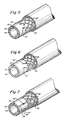
- FIG. 1 is a fragmented illustration of the catheter of the invention with the retroperfus.on balloon illustrated in an inflated configuration;
- FIG. 2 is an enlarged side elevation of a partly fragmented section of the distal end of the catheter with the balloon in an inflated configuration;
- FIG. 3 is a sectional illustration of the balloon region of the catheter as seen along the line 3-3 of FIG. 2;
- FIG. 4 is a sectional illustration similar to FIG. 3 showing the balloon in a collapsed configuration;
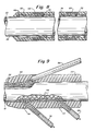
- FIG. 5 is a fragmented illustration of the main body of the catheter showing the composite structure of the catheter wall and illustrating one embodiment for containing the electrical leads;
- FIG. 6 is an illustration of the catheter body having a modified configuration for containing the electrical leads;
- FIG. 7 is an illustration of an embodiment of the catheter having still another configuration for containing the electrode leads;
- FIG. 8 is a longitudinal fragmented section of the catheter taken along the line 8-8 of FIG. 1 and illustrating the mounting and connection of the electrodes and the catheter structure in the region of the electrodes;
- FIG. 9 is a sectional illustration of the catheter taken through the furcated housing;
- FIG. 10 is a diagrammatic illustration of the retroperfusion catheter placed alone in the coronary sinus with the balloon in an inflated configuration as when delivering oxygenated blood;
- FIG. 11 is a sectional illustration seen along the line 11-11 of FIG. 10 with the balloon collapsed to permit drainage of the blood during systole.
- As shown in FIG. 1 the catheter includes an elongated catheter body indicated generally at 10, having a
proximal end 12 and adistal end 14. The inflatable anddeflatable retroperfusion balloon 16 is mounted to thedistal end 14 of thecatheter 10. Aproximal fitting 18 is mounted to theproximal end 12 of thecatheter body 10, the fitting 18 being of luer construction or a similar construction adapted for connection t? a suitable fluid connector. As shown in FIGS. 2 and 3 thecatheter body 10 has amain lumen 20 which extends longitudinally of the body and which terminates at adistal outlet port 22 at thedistal tip 24 of thecatheter body 10. Theproximal fitting 18 communicates directly with the proximal end of themain lumen 20. The region of thecatheter body 10 which extends through theballoon 16 has a plurality of inflation/deflation ports 26 which communicate between themain lumen 20 and the interior of theballoon 16. The cross-sectional flow area of the inflation-deflation ports 26 is substantially greater that that of thedistal outlet port 22 which assures that the balloon will inflate before fluid is ejected from the distal outlet port and also assures that theballoon 16 will collapse quickly when it is intended to be collapsed. - FIGS. 10 and 11 diagrammatically illustrate the placement and operation of the catheter to perform a retroperfusion procedure to direct oxygenated blood to the venous side of patient's heart. As shown, the catheter has been advanced through the superior venae cavae or inferior venae cavae into the right atrium and into the
coronary sinus 28. Thecoronary sinus 28 communicates through the greatcardiac vein 30 to smaller branches of the coronaryvenous tree 32 to the myocardium 33. As illustrated, the catheter is placed so that theballoon 16 is located within thecoronary sinus 28. Oxygenated blood is pumped in pulses synchronized with the patient's normal heart rhythm. When a pulse of oxygenated blood is pumped through the catheter, first it fills and inflates theballoon 16 through the larger flow area of theinflation ports 26 to form a temporary seal between the balloon and thelumen 34 of the coronary sinus. The seal prevents blood from draining away from the heart while the oxygenated blood is infused. After theballoon 16 has been inflated, the oxygenated blood is ejected from the smaller flow area of thedistal outlet port 22 into thecoronary sinus 28 and through the coronaryvenous tree 32 to the myocardium. During the systolic phase of the patient's heart rhythm theballoon 16 collapses to break its seal within the lumen of the coronary sinus and to permit the retroperfused blood to reverse its direction and flow through the vein, in a normal flow direction, away from the heart. - The
balloon 16 is mounted at the distal region of the catheter. It is molded, preferably in a dipping process, from polyvinyl chloride or similar material. The balloon preferably has a uniform wall thickness of about .005 inches and molded in a shape which, when the balloon is relaxed, defines somewhat of a cross or star-shaped in cross-section as shown in FIG. 4. The balloon may be considered as having a cross-sectional shape defined by alternating radially extendinglobes 36 and recessedportions 38. The recessedportions 38 will define longitudinal flow passages indicated at 40 in FIG. 11 within theblood vessel 28 to enable retroperfused blood to drain away from the retroperfusion site during systole. When theballoon 16 is expanded under the influence of a pulse of blood, it expands to the circular cross-section shown in FIG. 3 and into sealing contact with thelumen 34 of the blood vessel. Theballoon 16 also is formed to include aproximal neck portion 42 and adistal neck portion 44 at the proximal and distal ends of the balloon, respectively, by which the balloon may be attached to the catheter, as will be described in further detail. - As shown in further detail in FIGS. 5-9 the
catheter body 10 is formed from aninner core 46 which is surrounded by awire overbraid 48 which in turn is covered by anouter jacket 50. Theinner core 46 is an extruded tube formed from a soft flexible material, preferably a urethane composition. Theinner core 46 extends the full length of the catheter, from theproximal fitting 18 to thedistal tip 24. Theinner core 46 is extruded to define themain lumen 20 and also to define a smallersecondary lumen 52 which, as will be described, provides pressure measurement and medication infusion capability for the catheter. - In order to provide the catheter with adequate stiffness, a
wire overbraid 48 is formed to define a sheath which surrounds theinner core 46. The wire for the overbraid preferably is formed from stainless steel and may have a diameter of the order of .002-.003 inches. The overbraided wire sheath stiffens sufficiently the catheter so that torque may be transmitted to the distal end of the catheter by manipulation of the catheter from its proximal end. It is desirable to be able to transmit torque to the distal end to facilitate guiding of the distal end of the catheter through the patient's venous system to the coronary sinus. - The
inner core 46 and wire overbraid 48 are encased in anouter jacket 50. The outertubular jacket 50 also may be formed from urethane and fits firmly about thecore 46 andoverbraid 48. The compositeinner core 46, wire overbraid 48 andouter jacket 50 extend from theproximal fitting 18 toward thedistal tip 24 of the catheter. The wire overbraid 48 andouter jacket 50 terminate short of thedistal tip 24 of the catheter so that adistal segment 54 of theinner core 46 protrudes distally beyond theoverbraid 48 andouter jacket 50. Thedistal segment 54 provides a soft, flexible and atraumatic tip which reduces substantially the risk of trauma or injury to the patient. - By way of dimensional example, the inner core may have an outer diameter of the order of .090 inches and a wall thickness of about .018 inches. The
outer jacket 50 may have a wall thickness of about .003-.005 inches. The catheter may be made in varying lengths and, for example, may be of between 50 cms. and 100 cms. in length. - In order to facilitate steering of the distal end of the catheter, the distal end is provided with a preset curve or bend as indicated in FIG. 1. The curve may be similar to the curve formed in Cournand catheters. The combination of the curved distal end and the ability of the catheter shaft to transmit torque from the proximal end to the distal end enables the physician to control the drection in which the distal end extends, as it is advanced through the patient's blood vessels.
- The
balloon 16 is attached to thedistal segment 54 by adhesively attaching theneck portions distal segment 54. The inflation/deflation ports 26 are formed in thedistal segment 54 of theinner core 46 to communicate directly with the interior of theballoon 16. - The portion of the
distal segment 54 of theinner core 46 which is located beyond thefluid port 56 is tapered to a necked-down configuration having a first tapered portion 53 and a terminal untapered portion 55. The diameter of themain lumen 20 reduces progressively as it passes through the necked-down tip 53, 55 of the catheter to define a relatively smalldiameter outlet port 22 at thedistal tip 24. By way of example, in the preferred embodiment of the invention, themain lumen 20 may have an inner diameter of the order of .055 inches. The diameter of theoutlet port 22 may be reduced to an inner diameter of about .045 inches. In the preferred embodiment of the invention six or eight inflation/deflation ports 26 are provided and each may have a diameter of the order of .038 inches. Thus, the flow area defined by the inflation/deflation ports is substantially greater than that at the mostdistal outlet port 22. - The balloon is located so that its
distal neck 44 is spaced proximally from thedistal tip 24 of the catheter. The distal end of theinner core 46, which extends distally beyond thedistal neck 44 of theballoon 16 is formed to define afluid port 56 through the wall of theinner core 46. Thefluid port 56 communicates with and defines the distal end of thesecondary lumen 52, thereby to provide an independent means of fluid communication from the proximal end of the catheter to a location outside of the catheter and distally of the balloon. As shown in FIG. 9 access to thesecondary lumen 52 from the proximal end of the catheter is provided by means oftubular side leg 58 which is connected to the proximal regon of the catheter by afurcated housing 60. The lumen 59 of theside leg 58 is connected to the catheter within thefurcated housing 60 so as to be in communication with thesecondary lumen 52. The distal end of theside leg 58 may be reduced in diameter, as indicated at 57 to enable the reduced diameter portion 57 to be passed through the wall of theinner core 46 and into thesecondary lumen 52. The proximal end of the side leg 58 s provided with a fitting 62, such as a Luer-Lok device. The fitting 62 is connectible to a pressure monitoring device by which the pressure downstream of theballoon 16 may be measured. It also may be connected to a source of liquid infusion, for example, to infuse medication directly to the venous site. - The catheter also includes electrode means by which the patient's E.C.G. may be monitored. As shown in FIGS. 1 and 8 the catheter preferably has a pair of
ring electrodes distal electrode 66, is placed on the catheter close enough to the balloon so that when the balloon is in place in the coronary sinus, thedistal electrode 66 also will be disposed within thecoronary sinus 28. For example, in the illustrative embodiment, thedistal electrode 66 may be located about 2 to 3 cm. proximally of theballoon 16. Theproximal electrode 64 is spaced from the distal electrode and may be located so that it will be disposed in the patient's right atrium or in the coronary sinus. Theelectrodes outer jacket 50 to present a smooth external configuration. - The
electrodes electrical leads furcated housing 60 which is molded to and about thecatheter body 10, theleads side leg 58. The electrical leads 68, 70 are electrically connected to theelectrodes wires wires - The
wires electrodes wires outer jacket 50 and are wound a number of turns about theouter jacket 50. Theelectrodes wires wires outer jacket 50 are contained securely by the surroundingring electrodes outer jacket 50 may be slightly compressed in the region of the electrodes so as to maintain the outer surface of theelectrodes outer jacket 50. A suitable adhesive also may be used to secure the electrodes and wires in place on the catheter, if desired. - FIG. 6 illustrates an alternate arrangement for the wires 72ʹ, 74ʹ in which the wires are wound helically about the overbraid without forming a direct part of the overbraid structure itself.
- FIG. 7 illustrates still another embodiment in which the wires 72ʺ, 74ʺ are contained within longitudinally extending
channels inner core 46. In each case, the wires are individually insulated. The distal end of each of the wires is connected to its associatedelectrode - As mentioned above the distal region of the catheter preferably is formed to define a curved configuration to facilitate guiding of the catheter as it is advanced through the patient's blood vessels. It is preferred, however, that the
balloon 16 be mounted on an uncurved, straight portion of the catheter. To that end, the curve is formed in thedistal segment 58 of the catheter so that the portion which is to carry theballon 16 is straight, or at least is provided with a minimal curve. - In use the catheter is placed, as described, with the balloon and at least the distal electrode located in the patient's
coronary sinus 28. The fitting 18 is connected to the outlet from a suitable synchronous pumping system which also is connected to theleads
Claims (18)
an elongated catheter body having a proximal end and a distal end, the body having a central lumen extending from its proximal end to its distal end, the lumen terminating at its distal end at a distal outlet port;
a ballon mounted to the distal end of the body, the balloon being in communication with the central lumen whereby the balloon may be inflated and deflated in response to changes in pressure within the central lumen; and
means for monitoring the pressure at a location distally of the balloon independently of operation of the balloon.
a secondary lumen formed through and along the catheter body, the secondary lumen having an outlet port distally of the balloon, the secondary lumen having an inlet at the proximal region of the catheter.
the catheter body being formed from an inner elongated tubular core having the main lumen formed therethrough; and
the second lumen being formed through the wall of the core.
a wire overbraid formed about the inner core; and
an outer jacket formed about the wire overbraid.
a furcation formed on the catheter, the furcation having a side leg in communication with the secondary lumen; and
a proximal fitting attached to the proximal end of the catheter body.
the wire overbraid and outer jacket terminating short of the distal end of the tubular core thereby to define a distally protruding segment of the tubular core;
said balloon being mounted on the distal segment.
said inner core being formed from a relatively soft, flexible material whereby the distal segment of the catheter is relatively soft and flexible thereby to present a relatively atraumatic tip as the catheter is advanced in a patient's vascular system.
the distal region of the catheter being curved.
means carried by the catheter body for monitoring electrical activity of the blood vessel in which the balloon is placed.
a pair of spaced electrodes on the catheter body proximally of the balloon; and
electrical conductor means extending through the catheter body and being connected to the electrodes at their distal ends, the proximal ends of the conductor being connected to leads extending out of the catheter body at the proximal region of the catheter body.
a catheter body being formed from an inner elongated tubular core having the main lumen formed therethrough:
the secondary lumen being formed through the wall of the core;
a wire overbraid formed about the inner core; and
an outer jacket formed about the wire overbraid.
said electrically conductor means being formed integrally with and defining strands of the wire overbraid.
said electrically conductor means being wrapped helically about the wire overbraid.
means defining longitudinally extending grooves in the outer surface of the inner core, said electrical conductor means being disposed within the grooves.
an elongated catheter body having a lumen extending therethrough and a retroperfusion balloon at its distal end, the lumen being in communication with the interior of the balloon, the lumen terminating in a distal outlet tip; and
electrode means carried by the catheter body for monitoring electrical activity of the blood vessel in which the balloon is placed.
placing a retroperfusion catheter in a selected location of a patient's venous system and performing a retroperfusion procedure;
selectively performing at least one of the steps of monitoring the pressure in the blood vessel sensing electrical activity of the blood vessel, applying a pacing pulse to the blood vessel and infusion of liquids into the blood vessel independently of the retroperfusion procedure.
performing at least said steps of monitoring the pressure in the blood vessel and sensing electrical activity of the blood vessel.
Applications Claiming Priority (2)
| Application Number | Priority Date | Filing Date | Title |
|---|---|---|---|
| US87361586A | 1986-06-12 | 1986-06-12 | |
| US873615 | 1986-06-12 |
Publications (2)
| Publication Number | Publication Date |
|---|---|
| EP0249338A2 true EP0249338A2 (en) | 1987-12-16 |
| EP0249338A3 EP0249338A3 (en) | 1988-12-14 |
Family
ID=25361992
Family Applications (1)
| Application Number | Title | Priority Date | Filing Date |
|---|---|---|---|
| EP87304198A Withdrawn EP0249338A3 (en) | 1986-06-12 | 1987-05-12 | Retroperfusion catheter |
Country Status (3)
| Country | Link |
|---|---|
| EP (1) | EP0249338A3 (en) |
| JP (1) | JPS62298373A (en) |
| AU (1) | AU7413387A (en) |
Cited By (46)
| Publication number | Priority date | Publication date | Assignee | Title |
|---|---|---|---|---|
| WO1989010155A1 (en) * | 1988-04-28 | 1989-11-02 | Research Medical, Inc. | Retrograde venous cardioplegia catheters and methods of use and manufacture |
| EP0366807A1 (en) * | 1988-03-29 | 1990-05-09 | Nippon Zeon Co., Ltd. | Temporary pacing catheter |
| EP0369044A1 (en) * | 1988-11-14 | 1990-05-23 | Siemens-Elema AB | Electrode arrangement |
| EP0387453A1 (en) * | 1989-03-17 | 1990-09-19 | C.R. Bard, Inc. | Steerable guidewire having electrodes for measuring vessel cross-section and blood flow |
| EP0392099A1 (en) * | 1986-05-12 | 1990-10-17 | Bernard L. Charms | Defibrillation apparatus |
| AU603021B2 (en) * | 1987-12-01 | 1990-11-01 | Terumo Kabushiki Kaisha | Balloon cathether |
| US5013296A (en) * | 1989-09-21 | 1991-05-07 | Research Medical, Inc. | Antegrade cardioplegia cannula |
| US5084031A (en) * | 1989-09-12 | 1992-01-28 | Research Medical, Inc. | Cardioplegia three-way double stopcock |
| US5184621A (en) * | 1991-05-29 | 1993-02-09 | C. R. Bard, Inc. | Steerable guidewire having electrodes for measuring vessel cross-section and blood flow |
| WO1993014811A1 (en) * | 1992-01-28 | 1993-08-05 | Medtronic, Inc. | Removable endocardial lead |
| WO1993020881A1 (en) * | 1992-04-09 | 1993-10-28 | Scimed Life Systems, Inc. | Dilatation catheter with polyimide-encased stainless steel braid proximal shaft |
| EP0594201A2 (en) * | 1992-10-23 | 1994-04-27 | Terumo Kabushiki Kaisha | Catheter tube and method of manufacturing the tube |
| US5324260A (en) * | 1992-04-27 | 1994-06-28 | Minnesota Mining And Manufacturing Company | Retrograde coronary sinus catheter |
| WO1994020166A1 (en) * | 1993-03-02 | 1994-09-15 | Metra Aps | Dilation catheter |
| NL9300670A (en) * | 1993-04-20 | 1994-11-16 | Cordis Europ | Catheter with electrically conductive wire reinforcement. |
| US5395331A (en) * | 1992-04-27 | 1995-03-07 | Minnesota Mining And Manufacturing Company | Retrograde coronary sinus catheter having a ribbed balloon |
| WO1995009561A1 (en) * | 1993-10-01 | 1995-04-13 | Target Therapeutics, Inc. | Sheathed multipolar catheter and multipolar guidewire for sensing cardiac electrical activity |
| US5423745A (en) * | 1988-04-28 | 1995-06-13 | Research Medical, Inc. | Irregular surface balloon catheters for body passageways and methods of use |
| US5451232A (en) * | 1991-10-07 | 1995-09-19 | Medrad, Inc. | Probe for MRI imaging and spectroscopy particularly in the cervical region |
| EP0385367B1 (en) * | 1989-02-27 | 1995-10-25 | Medrad Inc. | Intracavity probe and interface device for MRI imaging and spectroscopy |
| US5476095A (en) * | 1989-02-24 | 1995-12-19 | Medrad, Inc. | Intracavity probe and interface device for MRI imaging and spectroscopy |
| US5487730A (en) * | 1992-12-30 | 1996-01-30 | Medtronic, Inc. | Balloon catheter with balloon surface retention means |
| US5533987A (en) * | 1992-04-09 | 1996-07-09 | Scimed Lifesystems, Inc. | Dilatation catheter with polymide encased stainless steel braid proximal shaft |
| US5558644A (en) * | 1991-07-16 | 1996-09-24 | Heartport, Inc. | Retrograde delivery catheter and method for inducing cardioplegic arrest |
| EP0786266A1 (en) * | 1996-01-26 | 1997-07-30 | B. Braun Melsungen Ag | Catheter set with ECG monitoring lead capability |
| EP0794811A1 (en) * | 1994-11-23 | 1997-09-17 | Micro Interventional Systems, Inc. | High torque balloon catheter |
| EP0798016A2 (en) * | 1996-03-28 | 1997-10-01 | Vitatron Medical B.V. | Implantable stimulus system having stimulus generator with pressure sensor and common lead for transmitting stimulus pulses to a body location and pressure signals from the body location to the stimulus generator |
| EP0841963A1 (en) * | 1994-12-07 | 1998-05-20 | Heartport, Inc. | Cardioplegia catheter system |
| US5765568A (en) | 1994-05-27 | 1998-06-16 | Heartport, Inc. | Catheter system and method for venting the left ventricle |
| US5779685A (en) * | 1995-11-13 | 1998-07-14 | Quest Medical, Inc. | Retrograde cardioplegia catheter and method of use |
| WO1998055027A2 (en) * | 1997-06-05 | 1998-12-10 | Vascular Science Inc. | Minimally invasive medical bypass methods and apparatus using partial relocation of tubular body conduit |
| EP0906132A4 (en) * | 1994-05-06 | 1999-04-07 | ||
| US5967978A (en) * | 1993-01-29 | 1999-10-19 | Cardima, Inc. | Intravascular sensing device |
| US6171297B1 (en) | 1998-06-30 | 2001-01-09 | Schneider (Usa) Inc | Radiopaque catheter tip |
| US6932792B1 (en) * | 1997-04-23 | 2005-08-23 | Frederick G. St. Goar | Antegrade cardioplegia catheter and method |
| US7004925B2 (en) | 2003-02-25 | 2006-02-28 | Cleveland Clinic Foundation | Apparatus and method for auto-retroperfusion of a coronary vein |
| US7004926B2 (en) | 2003-02-25 | 2006-02-28 | Cleveland Clinic Foundation | Apparatus and method for auto-retroperfusion of a coronary vein |
| US7473237B2 (en) | 2003-02-25 | 2009-01-06 | The Cleveland Clinic Foundation | Apparatus for auto-retroperfusion of a coronary vein |
| US7747310B2 (en) | 2002-05-16 | 2010-06-29 | Medrad, Inc. | System and method of obtaining images and spectra of intracavity structures using 3.0 Tesla magnetic resonance systems |
| US7885704B2 (en) | 2004-11-15 | 2011-02-08 | Medrad, Inc. | Intracavity probes and interfaces therefor for use in obtaining images and spectra of intracavity structures using high field magnetic resonance systems |
| CN102861373A (en) * | 2012-09-25 | 2013-01-09 | 厦门大学附属中山医院 | Central venous catheter with wall adherence preventing device for dialysis |
| EP3215209A4 (en) * | 2014-11-05 | 2018-06-13 | Clph, Llc | Catheter devices and methods for making them |
| EP3194001A4 (en) * | 2014-09-21 | 2018-07-04 | Clph, Llc | Catheter devices and methods for making them |
| WO2020247218A1 (en) | 2019-06-04 | 2020-12-10 | Surefire Medical, Inc. | Atraumatic occlusive system with compartment for measurement of vascular pressure change |
| CN113599675A (en) * | 2021-09-14 | 2021-11-05 | 蚌埠医学院第一附属医院(蚌埠医学院附属肿瘤医院) | Femoral artery intubation and catheterization method capable of monitoring and increasing blood supply of lower limbs |
| EP4218625A1 (en) * | 2022-02-01 | 2023-08-02 | Albert-Ludwigs-Universität Freiburg | A dual catheter arrangement and system for reperfusion of an ischemic tissue region via a coronary vessel |
Families Citing this family (7)
| Publication number | Priority date | Publication date | Assignee | Title |
|---|---|---|---|---|
| US5584803A (en) | 1991-07-16 | 1996-12-17 | Heartport, Inc. | System for cardiac procedures |
| US6482171B1 (en) | 1991-07-16 | 2002-11-19 | Heartport, Inc. | Multi-lumen catheter |
| US5769812A (en) | 1991-07-16 | 1998-06-23 | Heartport, Inc. | System for cardiac procedures |
| US6224619B1 (en) | 1991-12-17 | 2001-05-01 | Heartport, Inc. | Blood vessel occlusion trocar having size and shape varying insertion body |
| US5755687A (en) | 1997-04-01 | 1998-05-26 | Heartport, Inc. | Methods and devices for occluding a patient's ascending aorta |
| US6159178A (en) | 1998-01-23 | 2000-12-12 | Heartport, Inc. | Methods and devices for occluding the ascending aorta and maintaining circulation of oxygenated blood in the patient when the patient's heart is arrested |
| US20060184191A1 (en) | 2005-02-11 | 2006-08-17 | Boston Scientific Scimed, Inc. | Cutting balloon catheter having increased flexibility regions |
Citations (5)
| Publication number | Priority date | Publication date | Assignee | Title |
|---|---|---|---|---|
| US3585983A (en) * | 1968-03-05 | 1971-06-22 | Adrian Kantrowitz | Cardiac assisting pump |
| US3707960A (en) * | 1970-09-03 | 1973-01-02 | Us Health | Balloon cardiac assisting pump having intraaortic electrocardiographic electrodes |
| GB2029236A (en) * | 1978-09-01 | 1980-03-19 | Durand A | Coatheter with bulb |
| US4284073A (en) * | 1977-10-11 | 1981-08-18 | Krause Horst E | Method and apparatus for pumping blood within a vessel |
| EP0150960A2 (en) * | 1984-01-20 | 1985-08-07 | Corday, Eliot, Dr. | Catheter for retroinfusion of pharmacologic agents |
-
1987
- 1987-05-12 EP EP87304198A patent/EP0249338A3/en not_active Withdrawn
- 1987-06-11 AU AU74133/87A patent/AU7413387A/en not_active Abandoned
- 1987-06-12 JP JP62146845A patent/JPS62298373A/en active Pending
Patent Citations (5)
| Publication number | Priority date | Publication date | Assignee | Title |
|---|---|---|---|---|
| US3585983A (en) * | 1968-03-05 | 1971-06-22 | Adrian Kantrowitz | Cardiac assisting pump |
| US3707960A (en) * | 1970-09-03 | 1973-01-02 | Us Health | Balloon cardiac assisting pump having intraaortic electrocardiographic electrodes |
| US4284073A (en) * | 1977-10-11 | 1981-08-18 | Krause Horst E | Method and apparatus for pumping blood within a vessel |
| GB2029236A (en) * | 1978-09-01 | 1980-03-19 | Durand A | Coatheter with bulb |
| EP0150960A2 (en) * | 1984-01-20 | 1985-08-07 | Corday, Eliot, Dr. | Catheter for retroinfusion of pharmacologic agents |
Cited By (77)
| Publication number | Priority date | Publication date | Assignee | Title |
|---|---|---|---|---|
| EP0392099A1 (en) * | 1986-05-12 | 1990-10-17 | Bernard L. Charms | Defibrillation apparatus |
| AU603021B2 (en) * | 1987-12-01 | 1990-11-01 | Terumo Kabushiki Kaisha | Balloon cathether |
| EP0366807A1 (en) * | 1988-03-29 | 1990-05-09 | Nippon Zeon Co., Ltd. | Temporary pacing catheter |
| EP0366807A4 (en) * | 1988-03-29 | 1992-08-12 | Nippon Zeon Co., Ltd. | Temporary pacing catheter |
| US5021045A (en) * | 1988-04-28 | 1991-06-04 | Research Medical, Inc. | Retrograde venous cardioplegia catheters and methods of use and manufacture |
| EP0411039A1 (en) * | 1988-04-28 | 1991-02-06 | Research Medical, Inc. | Retrograde venous cardioplegia catheters and methods of use and manufacture |
| EP0411039A4 (en) * | 1988-04-28 | 1991-04-10 | Research Medical, Inc. | Retrograde venous cardioplegia catheters and methods of use and manufacture |
| US5423745A (en) * | 1988-04-28 | 1995-06-13 | Research Medical, Inc. | Irregular surface balloon catheters for body passageways and methods of use |
| AU633824B2 (en) * | 1988-04-28 | 1993-02-11 | Research Medical, Inc. | Retrograde venous cardioplegia catheters and methods of use and manufacture |
| WO1989010155A1 (en) * | 1988-04-28 | 1989-11-02 | Research Medical, Inc. | Retrograde venous cardioplegia catheters and methods of use and manufacture |
| EP0369044A1 (en) * | 1988-11-14 | 1990-05-23 | Siemens-Elema AB | Electrode arrangement |
| US5476095A (en) * | 1989-02-24 | 1995-12-19 | Medrad, Inc. | Intracavity probe and interface device for MRI imaging and spectroscopy |
| EP0385367B1 (en) * | 1989-02-27 | 1995-10-25 | Medrad Inc. | Intracavity probe and interface device for MRI imaging and spectroscopy |
| EP0387453A1 (en) * | 1989-03-17 | 1990-09-19 | C.R. Bard, Inc. | Steerable guidewire having electrodes for measuring vessel cross-section and blood flow |
| US5084031A (en) * | 1989-09-12 | 1992-01-28 | Research Medical, Inc. | Cardioplegia three-way double stopcock |
| US5013296A (en) * | 1989-09-21 | 1991-05-07 | Research Medical, Inc. | Antegrade cardioplegia cannula |
| US5184621A (en) * | 1991-05-29 | 1993-02-09 | C. R. Bard, Inc. | Steerable guidewire having electrodes for measuring vessel cross-section and blood flow |
| US5558644A (en) * | 1991-07-16 | 1996-09-24 | Heartport, Inc. | Retrograde delivery catheter and method for inducing cardioplegic arrest |
| US5913842A (en) * | 1991-07-16 | 1999-06-22 | Heartport, Inc. | Retrograde delivery catheter and method for inducing cardioplegic arrest |
| US5738652A (en) | 1991-07-16 | 1998-04-14 | Heartport, Inc. | Retrograde delivery catheter and method for inducing cardioplegic arrest |
| US5451232A (en) * | 1991-10-07 | 1995-09-19 | Medrad, Inc. | Probe for MRI imaging and spectroscopy particularly in the cervical region |
| US5338295A (en) * | 1991-10-15 | 1994-08-16 | Scimed Life Systems, Inc. | Dilatation catheter with polyimide-encased stainless steel braid proximal shaft |
| WO1993014811A1 (en) * | 1992-01-28 | 1993-08-05 | Medtronic, Inc. | Removable endocardial lead |
| US5533987A (en) * | 1992-04-09 | 1996-07-09 | Scimed Lifesystems, Inc. | Dilatation catheter with polymide encased stainless steel braid proximal shaft |
| WO1993020881A1 (en) * | 1992-04-09 | 1993-10-28 | Scimed Life Systems, Inc. | Dilatation catheter with polyimide-encased stainless steel braid proximal shaft |
| US5324260A (en) * | 1992-04-27 | 1994-06-28 | Minnesota Mining And Manufacturing Company | Retrograde coronary sinus catheter |
| US5395331A (en) * | 1992-04-27 | 1995-03-07 | Minnesota Mining And Manufacturing Company | Retrograde coronary sinus catheter having a ribbed balloon |
| US5620418A (en) * | 1992-04-27 | 1997-04-15 | Minnesota Mining And Manufacturing Company | Retrograde coronary sinus catheter |
| US5807326A (en) * | 1992-04-27 | 1998-09-15 | Minnesota Mining And Manufacturing Company | Retrograde coronary sinus catheter |
| EP0594201A3 (en) * | 1992-10-23 | 1995-04-05 | Terumo Corp | Catheter tube and method of manufacturing the tube. |
| EP0594201A2 (en) * | 1992-10-23 | 1994-04-27 | Terumo Kabushiki Kaisha | Catheter tube and method of manufacturing the tube |
| US5538513A (en) * | 1992-10-23 | 1996-07-23 | Terumo Kabushiki Kaisha | Catheter tube having a filamentous reinforcing layer |
| US5487730A (en) * | 1992-12-30 | 1996-01-30 | Medtronic, Inc. | Balloon catheter with balloon surface retention means |
| US5720726A (en) * | 1992-12-30 | 1998-02-24 | Medtronic, Inc. | Balloon catheter having retention enhancements on the balloon |
| US6141576A (en) * | 1993-01-29 | 2000-10-31 | Cardima, Inc. | Intravascular sensing device |
| US5967978A (en) * | 1993-01-29 | 1999-10-19 | Cardima, Inc. | Intravascular sensing device |
| WO1994020166A1 (en) * | 1993-03-02 | 1994-09-15 | Metra Aps | Dilation catheter |
| US5591142A (en) * | 1993-04-20 | 1997-01-07 | Cordis Corporation | Catheter with wire reinforcement having good electrical conductivity |
| EP0629416A1 (en) * | 1993-04-20 | 1994-12-21 | Cordis Europa N.V. | Catheter with wire reinforcement having good electrical conductivity |
| NL9300670A (en) * | 1993-04-20 | 1994-11-16 | Cordis Europ | Catheter with electrically conductive wire reinforcement. |
| US5549109A (en) * | 1993-10-01 | 1996-08-27 | Target Therapeutics, Inc. | Sheathed multipolar catheter and multipolar guidewire for sensing cardiac electrical activity |
| WO1995009561A1 (en) * | 1993-10-01 | 1995-04-13 | Target Therapeutics, Inc. | Sheathed multipolar catheter and multipolar guidewire for sensing cardiac electrical activity |
| EP0906132A1 (en) * | 1994-05-06 | 1999-04-07 | Trustees Of Boston University | Coronary sinus reperfusion catheter |
| EP0906132A4 (en) * | 1994-05-06 | 1999-04-07 | ||
| US5765568A (en) | 1994-05-27 | 1998-06-16 | Heartport, Inc. | Catheter system and method for venting the left ventricle |
| EP0794811A1 (en) * | 1994-11-23 | 1997-09-17 | Micro Interventional Systems, Inc. | High torque balloon catheter |
| EP0794811A4 (en) * | 1994-11-23 | 1998-10-28 | Micro Interventional Systems I | High torque balloon catheter |
| EP0841963A4 (en) * | 1994-12-07 | 1998-08-19 | Heartport Inc | Cardioplegia catheter system |
| EP0841963A1 (en) * | 1994-12-07 | 1998-05-20 | Heartport, Inc. | Cardioplegia catheter system |
| AU709259B2 (en) * | 1995-01-12 | 1999-08-26 | Edwards Lifesciences Ag | Retrograde delivery catheter and method for inducing cardioplegic arrest |
| US5779685A (en) * | 1995-11-13 | 1998-07-14 | Quest Medical, Inc. | Retrograde cardioplegia catheter and method of use |
| EP0786266A1 (en) * | 1996-01-26 | 1997-07-30 | B. Braun Melsungen Ag | Catheter set with ECG monitoring lead capability |
| EP0798016A3 (en) * | 1996-03-28 | 1998-12-16 | Vitatron Medical B.V. | Implantable stimulus system having stimulus generator with pressure sensor and common lead for transmitting stimulus pulses to a body location and pressure signals from the body location to the stimulus generator |
| EP0798016A2 (en) * | 1996-03-28 | 1997-10-01 | Vitatron Medical B.V. | Implantable stimulus system having stimulus generator with pressure sensor and common lead for transmitting stimulus pulses to a body location and pressure signals from the body location to the stimulus generator |
| US6932792B1 (en) * | 1997-04-23 | 2005-08-23 | Frederick G. St. Goar | Antegrade cardioplegia catheter and method |
| WO1998055027A3 (en) * | 1997-06-05 | 2001-06-07 | Vascular Science Inc | Minimally invasive medical bypass methods and apparatus using partial relocation of tubular body conduit |
| WO1998055027A2 (en) * | 1997-06-05 | 1998-12-10 | Vascular Science Inc. | Minimally invasive medical bypass methods and apparatus using partial relocation of tubular body conduit |
| US6171297B1 (en) | 1998-06-30 | 2001-01-09 | Schneider (Usa) Inc | Radiopaque catheter tip |
| US6652692B2 (en) | 1998-06-30 | 2003-11-25 | Boston Scientific Scimed, Inc. | Method of making radiopaque catheter tip |
| US7747310B2 (en) | 2002-05-16 | 2010-06-29 | Medrad, Inc. | System and method of obtaining images and spectra of intracavity structures using 3.0 Tesla magnetic resonance systems |
| US8989841B2 (en) | 2002-05-16 | 2015-03-24 | Bayer Medical Care Inc. | Interface devices for use with intracavity probes for high field strength magnetic resonance systems |
| US7004926B2 (en) | 2003-02-25 | 2006-02-28 | Cleveland Clinic Foundation | Apparatus and method for auto-retroperfusion of a coronary vein |
| US7473237B2 (en) | 2003-02-25 | 2009-01-06 | The Cleveland Clinic Foundation | Apparatus for auto-retroperfusion of a coronary vein |
| US7004925B2 (en) | 2003-02-25 | 2006-02-28 | Cleveland Clinic Foundation | Apparatus and method for auto-retroperfusion of a coronary vein |
| WO2006031597A1 (en) * | 2004-09-10 | 2006-03-23 | The Cleveland Clinic Foundation | Apparatus and method for auto-retroperfusion of a coronary vein |
| US7885704B2 (en) | 2004-11-15 | 2011-02-08 | Medrad, Inc. | Intracavity probes and interfaces therefor for use in obtaining images and spectra of intracavity structures using high field magnetic resonance systems |
| CN102861373A (en) * | 2012-09-25 | 2013-01-09 | 厦门大学附属中山医院 | Central venous catheter with wall adherence preventing device for dialysis |
| EP3194001A4 (en) * | 2014-09-21 | 2018-07-04 | Clph, Llc | Catheter devices and methods for making them |
| US10124145B2 (en) | 2014-09-21 | 2018-11-13 | Clph, Llc | Catheter devices and methods for making them |
| EP3650071A1 (en) * | 2014-09-21 | 2020-05-13 | Clph, Llc | Catheter devices and methods for making them |
| EP3215209A4 (en) * | 2014-11-05 | 2018-06-13 | Clph, Llc | Catheter devices and methods for making them |
| EP4218882A3 (en) * | 2014-11-05 | 2023-08-16 | Clph, Llc | Catheter devices and methods for making them |
| WO2020247218A1 (en) | 2019-06-04 | 2020-12-10 | Surefire Medical, Inc. | Atraumatic occlusive system with compartment for measurement of vascular pressure change |
| EP3979923A4 (en) * | 2019-06-04 | 2023-07-26 | Trisalus Life Sciences, Inc. | Atraumatic occlusive system with compartment for measurement of vascular pressure change |
| CN113599675A (en) * | 2021-09-14 | 2021-11-05 | 蚌埠医学院第一附属医院(蚌埠医学院附属肿瘤医院) | Femoral artery intubation and catheterization method capable of monitoring and increasing blood supply of lower limbs |
| EP4218625A1 (en) * | 2022-02-01 | 2023-08-02 | Albert-Ludwigs-Universität Freiburg | A dual catheter arrangement and system for reperfusion of an ischemic tissue region via a coronary vessel |
| WO2023148069A1 (en) | 2022-02-01 | 2023-08-10 | Albert-Ludwigs-Universität Freiburg | A dual catheter arrangement and system for reperfusion of an ischemic tissue region via a coronary vessel |
Also Published As
| Publication number | Publication date |
|---|---|
| AU7413387A (en) | 1987-12-17 |
| EP0249338A3 (en) | 1988-12-14 |
| JPS62298373A (en) | 1987-12-25 |
Similar Documents
| Publication | Publication Date | Title |
|---|---|---|
| EP0249338A2 (en) | Retroperfusion catheter | |
| US20200337564A1 (en) | Catheter System and Method For Occluding A Body Vessel | |
| US4581017A (en) | Catheter systems | |
| EP0753322B1 (en) | Catheter for injecting fluid medication into an arterial wall | |
| US6602270B2 (en) | Reduced size intra-aortic balloon catheter | |
| CA2354628C (en) | Improved intra-aortic balloon catheter and insertion sheath | |
| US5533957A (en) | Method of tissue retroperfusion | |
| US4741328A (en) | Means for intraaortic assist and method of positioning a catheter therefor | |
| US4531936A (en) | Device and method for the selective delivery of drugs to the myocardium | |
| US6616597B2 (en) | Intra-aortic balloon catheter having a dual sensor pressure sensing system | |
| EP0238791B1 (en) | Tubular catheter | |
| US6592567B1 (en) | Kidney perfusion catheter | |
| EP2389974B1 (en) | A balloon catheter for introduction into a body vessel, in particular the coronary sinus | |
| US20060173441A1 (en) | Method and device for accessing a pericardial space | |
| AU7270498A (en) | Aortic arch occlusion and perfusion balloon catheter having pressure ports | |
| WO2001078574A2 (en) | Method and device for inserting leads into coronary veins | |
| AU1248492A (en) | Introduction balloon catheter | |
| JP2014501554A (en) | Cannula with bifurcated tip for cardiac assist device | |
| EP0768098A2 (en) | Catheter with fluid medication injectors | |
| EP0363117A1 (en) | A position-monitoring flow-directed catheter and method | |
| EP1210135B1 (en) | Improved intra-aortic balloon catheter having a tapered y-fitting | |
| US5772631A (en) | Procedure for alleviating arterial obstruction | |
| US7883500B2 (en) | Method and system to treat and prevent myocardial infarct expansion | |
| WO2002076545A2 (en) | Intra-aortic balloon catheter having a gas lumen insert | |
| JPH03198864A (en) | Auxiliary circulation apparatus |
Legal Events
| Date | Code | Title | Description |
|---|---|---|---|
| PUAI | Public reference made under article 153(3) epc to a published international application that has entered the european phase |
Free format text: ORIGINAL CODE: 0009012 |
|
| AK | Designated contracting states |
Kind code of ref document: A2 Designated state(s): BE DE ES FR GB IT NL |
|
| PUAL | Search report despatched |
Free format text: ORIGINAL CODE: 0009013 |
|
| AK | Designated contracting states |
Kind code of ref document: A3 Designated state(s): BE DE ES FR GB IT NL |
|
| STAA | Information on the status of an ep patent application or granted ep patent |
Free format text: STATUS: THE APPLICATION IS DEEMED TO BE WITHDRAWN |
|
| 18D | Application deemed to be withdrawn |
Effective date: 19890615 |
|
| RIN1 | Information on inventor provided before grant (corrected) |
Inventor name: SPECTOR, KENNETH ALAN Inventor name: HERMAN, STEPHEN JACK Inventor name: LEVENDUSKY, JOSEPH ANTHONY |