EP0247738B1 - Polarization independent coherent optical heterodyne receivers - Google Patents
Polarization independent coherent optical heterodyne receivers Download PDFInfo
- Publication number
- EP0247738B1 EP0247738B1 EP87303852A EP87303852A EP0247738B1 EP 0247738 B1 EP0247738 B1 EP 0247738B1 EP 87303852 A EP87303852 A EP 87303852A EP 87303852 A EP87303852 A EP 87303852A EP 0247738 B1 EP0247738 B1 EP 0247738B1
- Authority
- EP
- European Patent Office
- Prior art keywords
- signal
- polarization
- signals
- output
- optical
- Prior art date
- Legal status (The legal status is an assumption and is not a legal conclusion. Google has not performed a legal analysis and makes no representation as to the accuracy of the status listed.)
- Expired - Lifetime
Links
Images


Classifications
-
- H—ELECTRICITY
- H04—ELECTRIC COMMUNICATION TECHNIQUE
- H04B—TRANSMISSION
- H04B10/00—Transmission systems employing electromagnetic waves other than radio-waves, e.g. infrared, visible or ultraviolet light, or employing corpuscular radiation, e.g. quantum communication
- H04B10/60—Receivers
- H04B10/61—Coherent receivers
- H04B10/614—Coherent receivers comprising one or more polarization beam splitters, e.g. polarization multiplexed [PolMux] X-PSK coherent receivers, polarization diversity heterodyne coherent receivers
-
- H—ELECTRICITY
- H04—ELECTRIC COMMUNICATION TECHNIQUE
- H04B—TRANSMISSION
- H04B10/00—Transmission systems employing electromagnetic waves other than radio-waves, e.g. infrared, visible or ultraviolet light, or employing corpuscular radiation, e.g. quantum communication
- H04B10/60—Receivers
- H04B10/61—Coherent receivers
- H04B10/64—Heterodyne, i.e. coherent receivers where, after the opto-electronic conversion, an electrical signal at an intermediate frequency [fIF] is obtained
Landscapes
- Physics & Mathematics (AREA)
- Electromagnetism (AREA)
- Engineering & Computer Science (AREA)
- Computer Networks & Wireless Communication (AREA)
- Signal Processing (AREA)
- Optical Communication System (AREA)
Description
- The present invention relates to polarization independent optical heterodyne receivers.
- Optical heterodyne receivers are known in the art and comprise configurations as shown, for example, in U.S. patent 3,215,840 issued to C.F. Buhrer on November 2, 1965, and the article by G.T. Wrixon presented in the 8th European Microwave Conference, Paris, France, 4-8 September, 1978, at pages 717-719. In a conventional coherent optical communication system, the polarization of the received signal must be linear and aligned with the polarization axis of the local optical signal of the receiver. A departure from this condition rapidly degrades the performance of the coherent receiver. Such a degradation is likely to occur in a coherent fiber communication system because the polarization alignment between the two signals cannot be maintained permanently due to deformations of the fiber that randomly change the polarization state of the received signal.
- The use of a polarization maintaining fiber can solve such problem. Unfortunately, this option is likely to be precluded by the impossibility of changing the fibers of existing optical communication systems. An alternative solution consists of using an adaptive polarization technique. Such a system measures the polarization state of the received signal and uses this information to control the polarization of the received signal. This technique usually relies on an electro-mechanical or electro-optical feedback loop which may not be the most desirable solution for a communication system.
- JP-A-59.122140 discloses an optical heterodyne detector where performance is stable with respect to variations in the polarization state of the signal and mentions the possibility of adapting the detector for differential phase shift key demodulation.
- T.G. Hodgkinson and others in Electronics Letters, vol. 21, no. 19, 12th September 1985, 867-868 discloses a receiver as set out in the preamble of claim 1. In fact the receiver is highly sensitive to signal polarization and it is necessary to provide means for controlling the polarization very precisely.
- Therefore, the problem remaining in the prior art is to provide a coherent optical heterodyne receiver for differential phase shift key (DPSK) modulated signals which is independent of the polarization state of the received signal to avoid the deficiencies of the prior art optical heterodyne receivers.
- The foregoing problem in the prior art has been solved in accordance with the present invention as set out in claim 1.
- In the drawings:
- FIG. 1 is a block schematic of preferred arrangement of a polarization independent optical heterodyne receiver in accordance with the present invention which uses the entire available local signal for heterodyning;
- FIG. 2 is a block schematic showing the detection of the horizontal polarization component of the received signal in the arrangement of FIG. 1;
- FIG. 3 is a block schematic showing the detection of the vertical polarization component of the received signal in the arrangement of FIG. 1; and
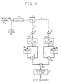
- FIG. 4 is a block schematic of an alternative arrangement of the polarization independent optical heterodyne receiver shown in FIG. 1 which uses only a fraction of the power supplied by the local optical signal for heterodyning.
- FIG. 4 is a block schematic of a coherent optical heterodyning receiver in accordance with the present invention whose performance is independent of the polarization state of the received optical signal. The effect of the polarization is eliminated by simple signal processing at the Intermediate Frequency (IF) frequency. The received optical signal, E s , is a Differential Phase Shift Keyed (DPSK) signal.
- In FIG. 4, the received polarized optical signal, E s , is combined with a polarized optical local oscillator signal, E L , in an optical combining means such as a
directional coupler 10, and the combined signals E s + E L are directed to a polarizingbeam splitter 11. Polarizing beam splitter 11 functions to direct the combined signals in a first polarization direction into afirst branch 12 and the combined signals in a second orthogonal polarization direction into asecond branch 13. The signals propagating inbranches second photodetector - More particularly, the two polarization directions are defined by the two polarization axes of polarizing
beam splitter 11. The local oscillator optical source, not shown, being used for heterodyning, is assumed to be linearly polarized. This local oscillator signal of power P L , radial frequency ω L and phase noise ϑ L (t) is given by

This signal power is equally divided between the two polarization axes of polarizingbeam splitter 11. Assuming that the two photodetectors have the same quantum efficiency, this can be accomplished by rotating polarizingbeam splitter 11 until the twophotodetectors photodetectors

and

The quantities α H and α V represent two arbitrary independent phases which depend on the state-of-polarization of P L , the opticaldirectional coupler 10, polarizingbeam splitter 11 and the respective paths seen by the two optical signals E s and E L . - When the received signal, E s , is linearly polarized, its value along its polarization axis is given by

where P s is the signal power, ω s the radial frequency, and ϑ s (t) the phase noise. The quantity M(t) represents the DPSK modulation given by
with α k equal to +1 or -1 during each bit of duration T having the pulse shape P(t). Under general conditions, the polarization of the received signal, E s , fluctuates randomly between all possible states of polarization. In this case, the received signal added to the local oscillator signal, E L , by means ofdirectional coupler 10 is split between the two polarization axes of polarizingbeam splitter 11. The resulting optical signals seen byphotodetectors

and

respectively, where β√
1- β² √
beam splitter 11. They also include the arbitrary, independent phase shifts introduced bydirectional coupler 10, thebeam splitter 11, and the respective paths seen by the two signals. - The currents provided by
phototdetectors 

and
The quantity η represents the quantum efficiency of the photodiodes; h is Planck's constant, ω is the optical frequency and e is the charge of the electron. The phase terms are given by

and

The remaining terms represent the shot noise generated in the IF bandwidth assumed to be equal to 1/T. Assuming that P L »P s , the shot noise terms are gaussian random variables of zero-mean and variance
where N is the average number of photons/bit. - In
branch 12, afterphotodetector 14, the output signal fromphotodetector 14 is passed through anIF filter 16 which functions to pass only the IF frequencies and reject all other frequencies. The resultant IF signal is divided equally by a dividing means 17 which can comprise, for example, a solder joint. The two portions of the divided signal propagate along separate paths, with one path including a delay means 18 for providing a delay of T seconds equal to one bit duration. The delayed and undelayed portions of the signal fromfilter 16 are multiplied in amultiplier 19. The same elements 16-19 are included inbranch 13 for processing the signal fromphotodetector 15 in a similar manner. The two signals frommultiplers 19 inbranches adder 20 to yield a baseband signal which is filtered in abaseband filter 21 to ensure only a baseband signal providing data recovery. - More particularly, the information M(t) M(t-T) is retrieved separately in the two
branches multiplexer 19 of each branch. This process provides a baseband signal whose magnitude is the square of the IF current magnitude and whose phase is equal to the phase difference between the two halves of the IF current. Providing that the IF frequency is adjusted to yield ΩT = 2nπ, and that the polarization state of the received signal, E s , is quasi-constant over a bit duration, the phase of the two baseband signals in the twobranches

Thus, the baseband signals are proportional to

and

where n₁(t) and n₂(t) are due to the noise terms in Equations (7) and (8), respectively. The magnitudes of the desired component of Equations (13) and (14) are respectively proportional to the received signal power in the horizontal and vertical polarization. Thus, the sum of the two signals yields the baseband signal

which is independent of the polarization state of the received signal. - The optical heterodyne receiver of FIG. 4 provides performance independent of the polarization state of the received signal. The result is obtained by demodulating separately the signals received in the two polarization axes of a
polarizing beam splitter 11 and adding these signals prior to detecting the data. The excess noise due to using twobranches directional coupler 10 and one branch including a photodetector (either 14 or 15) and the associated IFfilter 16,divider 17,delay 18 andmultiplier 19. The problem with the conventional receiver is that the polarization directions of the signals must be matched or, for example, β in Equations (5) and (6) approaches zero and no output signal is obtained. The disadvantage of the receiver of FIG. 4 is that the received signal is combined with the local oscillator signal by means of adirectional coupler 10 quasi-transparent to the received signal. Thus, most of the local oscillator signal, E L , is wasted in the unused fourth arm ofdirectional coupler 10 which is not connected to an optical path. - FIG. 1 illustrates a more efficient and, therefore, a preferred arrangement of the optical heterodyne receiver in accordance with the present invention. Instead of a
directional coupler 10, as shown in FIG. 4, the receiver of FIG 1 uses a mixer arrangement, which is shown to include a 3dB beam splitter 30, afirst mirror 33, a
polarization rotator 34 and asecond mirror 35. The 3dB beam splitter 30 functions to both (a) combine the received signal, E s , and the local oscillator signal, E L , and (b) transmit substantially equal portions of the combined signals E s + E L along substantially perpendicular first andsecond paths paths 
polarization rotator 34. - For purposes of illustration and not for purpose of limitation, the receiver shown in FIG. 1 disposes the
polarization rotator 34 inpath 32. It is to be understood, however, thatpolarization rotator 34 could be disposed inpath 31 instead. The polarization direction of the combined signal portion propagating alongsecond path 32 is rotated by
exemplary mirrors polarizing beam splitter 11 substantially perpendicular to the direction of the beam propagating alongpath 31. The two inputs topolarizing beam splitter 11 are transparent and reflective to a first and a second orthogonal orientation of polarization, respectively. Thus, the receiver arrangement of FIG. 1 differs from the arrangement of FIG. 4 by the substitution of both a 3dB beam splitter 30 and apolarization rotator 34 for thedirectional coupler 10, with the remaining circuitry remaining unchanged. - The operating mode of the receiver of FIG. 1 can be seen by first considering only the components of the received signal, E s , and the local oscillator signal, E L , which exit
polarizing beam splitter 11 on the same axis, e.g.,branch 12, as shown in FIG. 2. For purposes of illustration, the input polarization of these components will be defined as horizontal and denoted by the symbols of a dot surrounded by a circle as shown in FIG. 2. The horizontally polarized component of the received signal can be expressed as
The quantity β² denotes the fraction of the signal power P s received in this polarization direction; M(t) represents the signal DPSK modulation; ω₁ is the radial frequency; ϑ₁(t) is the phase noise and α is a slowly fluctuating phase depending on the polarization state of the received signal. The local oscillator signal is assumed to be linearly polarized in a plane which distributes the input power equally between the two outputs of the polarizing beam splitter. Thus, the horizontal component of this signal is
where P L represents the signal power supplied by the local optical source; ω₂ is the radial frequency and ϑ₂(t) is the phase noise. - The signals from Equations (16) and (17) are combined by 3
dB beam splitter 30 into two beams. The beam directed toward the polarizing beam splitter alongpath 31 traverses this device to go intobranch 12 of the receiver. This beam yields atphotodetector 14 of this branch
The quantity
represents the time delay sustained by the beam propagating along the distance L₁, separating 3dB beam splitter 30 from thepolarizing beam splitter 11. The phases φ T and φ R are phase shifts introduced, by the transmission and reflection, respectively, at 3dB beam splitter 30. These phase shifts are related by

Similar phase shifts φ' T and φ' R are introduced bypolarizing beam splitter 11. The last term δ A represents the phase due to thepath separating photodetector 14 frompolarizing beam splitter 11. - The other beam propagating along
path 32 provided by 3dB beam splitter 30, has its polarization axis rotated by
polarization rotator 34. This polarization direction is defined as the vertical axis and is denoted by the symbol ↑. The resulting beam is then directed toward the other input ofpolarizing beam splitter 11 byexemplary mirrors path 31. The incoming beam inpath 32, being vertically polarized, is reflected bypolarizing beam splitter 11 intobranch 12 of the receiver yielding atphotodetector 14 of this branch
The quantity L₂ represents the distance traveled by this beam between 3dB beam splitter 30 andpolarizing beam splitter 11. Note that the signals of Equations (16) and (17) provide no output signal intobranch 13 of the receiver. - Consider now the polarization components of the received signal and the local oscillator signal which are perpendicular relative to the signals of Equations (16) and (17) as shown in FIG. 3. The value of these signals are, respectively,

and
The quantity (1-β²)P s represents the signal power received in this polarization and α↑ is a phase which depends, as α, on the polarization state of this signal.
- The signals of Equations (21) and (22) are combined by 3
dB beam splitter 30 into two beams. In this case, the beam directed towardpolarizing beam splitter 11 alongpath 31 is reflected by this device intobranch 13 of the receiver becausepolarizing beam splitter 11 is reflective to the polarization direction of this beam. This beam yields atphotodetector 15 ofbranch 13
The quantity δ B represents a phase similar to δ A. The polarization of the second beam provided by
3dB beam splitter 30 and propagating alongpath 32 is rotated by
polarization rotator 34. As a result, this beam traversespolarizing beam splitter 11 into the direction ofbranch 13 of the receiver and yields atphotodetector 15 ofreceiver branch 13
Note that signals of Equations (21 and (22) feedonly branch 13 of the receiver while, as shown before, the signals of Equations (16) and (17) feedonly branch 12 of the receiver. Thus, the two polarization components of the received signal can be processed independently as in the receiver of FIG. 4. - The photodetector of each branch is fed by two perpendicularly polarized signals. For example,
branch 12 is fed the horizontally polarized combined signal pattern frompath 31 and the vertically polarized combined signal portions frompath 32 as shown in FIG. 2. Therefore, these signals are detected independently, contributing equally to the IF current at the radial frequency

and providing that the quantities M(t), ϑ₁(t) and ϑ₂(t) vary little over the time interval
the IF current supplied by the twophotodetectors 
and
The quantity η represents the quantum efficiency of the photodiodes; e is the charge of an electron; h is Planck's constant, and t' is the delayed time
The last two quantities n H (t') and n V (t') represent the shot noise generated by the detection process, which now can more easily dominate the receiver noise since the entire power of the local signal is available for heterodyning. - The remaining signal processing is identical to that described for the receiver of FIG. 4. Therefore, the receiver yields the same performance independent of the polarization of the received signal, providing that the signal modulation and the phase noise vary little over one-half of an IF period.
- From the foregoing discussion, it can be seen that the present receiver arrangements are independent of the polarization state of the received signal, E s . It is to be understood that the local oscillator signal, E L , is fixed in its polarization direction, but that the received signal E s , can randomly change during transmission and may not always be linear and aligned with the polarization of the local oscillator signal. Should the received signal be linear and aligned with the polarization of the local oscillator signal, then each of
branches polarization beam splitter 11, which currents are added inadder 20 to provide a predetermined signal level. If the received signal, however, randomly changes so that it is not linear and aligned with the local oscillator signal, then one of thebranches branches - It is to be understood that the above-described embodiments are simply illustrative of the principles of the invention. Various other modifications and changes may be made by those skilled in the art which will embody the principles of the invention and fall within the scope of the claims. For example, in FIGs. 1-3, the

polarization rotator 34 could be disposed inpath 31 instead of inpath 32. Under such conditions the signals normally received byphotodetector 14 would be received byphotodetector 15 and vice versa. Similarly, mirrors 33 and 35 could be replaced by any known redirecting means such as a prism or reflector. The circuit of FIGS. 1 and 2 can also be formed using optical fibers in the optical paths.
Claims (4)
- An optical heterodyne receiver comprising:
a first and a second input terminal for receiving a polarized differential phase shift keyed modulated optical input signal and a polarized optical local oscillator signal respectively;
combining and transmitting means (10,30) for combining the signals from the first and second input terminals and transmitting the combined signal along a first path;
a polarizing beam splitter (11) for directing components of the combined signals from the combining and transmitting means which are polarized in a first polarization direction along a first branch and components which are polarized in a second direction, orthogonal to the first direction, along a second branch, the polarizing beam splitter being oriented to divide the power of the polarized optical local oscillator signal received in the combined signals substantially equally into the first and second branches:
a first and second photodetector (14,15) disposed in the first and second branch respectively, for detecting the components of the combined signals propagating in the respective first and second branch and generating representative electrical signals at an output thereof;
first and second generating means (16-19) responsive to the output electrical signals from the first and second photodetectors respectively, for dividing the said electrical signal into two equal parts, multiplying one part by the other part delayed by one duration and generating an output baseband signal; and
adder means (20) for adding the output baseband signals from the first and second generating means,
CHARACTERIZED IN THAT
the polarization state of the modulated optical input signal is permitted to vary randomly with time; and
the frequency of the local oscillator signal differs from that of the modulated optical input signal by an intermediate frequency Ω such that the duration (T) of a bit is a whole number of cycles of the intermediate frequency. - An optical heterodyne receiver according to claim 1 wherein
the combining and transmitting means comprises a directional coupler (10). - An optical heterodyne receiver according to claim 1 wherein
the combining and transmitting means comprises:
an optical beam splitter (30) for both (a) combining the signals received at the first and second input terminals and (b)directing first and second substantially equal portions of the combined signals along first and second output paths, respectively; and
polarization rotating means (34) disposed in either one of the first and second output paths from the optical beam splitter for rotating the direction of polarization of the portion of the combined signals propagating in the one output path by
the polarizing beam splitter is responsive to the signals propagating in the first and second output paths from the combining and transmitting means for coaxially aligning both (a) the first combined signal portion with a first polarization direction propagating in the first output path and the second combined signal portion with a second polarization direction propagating in the second output path into an output beam directed along the first branch, and (b) the first combined signal portion with a second polarization direction propagating in the first output path and the second combined signal portion with a first polarization direction propagating in the second output path into an output beam directed along the second branch. - An optical heterodyne receiver according to claim 3 including redirecting means comprising a first (33) and a second (35) mirror disposed to, in combination, redirect the associated output path from the combining and transmitting means to intersect the other output path substantially perpendicular thereto.
Applications Claiming Priority (2)
| Application Number | Priority Date | Filing Date | Title |
|---|---|---|---|
| US06/860,823 US4723316A (en) | 1986-05-08 | 1986-05-08 | Polarization independent coherent optical heterodyne receivers |
| US860823 | 1986-05-08 |
Publications (3)
| Publication Number | Publication Date |
|---|---|
| EP0247738A2 EP0247738A2 (en) | 1987-12-02 |
| EP0247738A3 EP0247738A3 (en) | 1989-06-07 |
| EP0247738B1 true EP0247738B1 (en) | 1993-03-31 |
Family
ID=25334109
Family Applications (1)
| Application Number | Title | Priority Date | Filing Date |
|---|---|---|---|
| EP87303852A Expired - Lifetime EP0247738B1 (en) | 1986-05-08 | 1987-04-30 | Polarization independent coherent optical heterodyne receivers |
Country Status (5)
| Country | Link |
|---|---|
| US (1) | US4723316A (en) |
| EP (1) | EP0247738B1 (en) |
| JP (1) | JP2786188B2 (en) |
| CA (1) | CA1255755A (en) |
| DE (1) | DE3785081T2 (en) |
Families Citing this family (25)
| Publication number | Priority date | Publication date | Assignee | Title |
|---|---|---|---|---|
| US4697284A (en) * | 1986-05-08 | 1987-09-29 | American Telephone And Telegraph Company, At&T Bell Laboratories | Single-photodiode optical heterodyne mixers |
| US4723317A (en) * | 1986-05-08 | 1988-02-02 | American Telephone And Telegraph Company, At&T Bell Laboratories | Optical heterodyne mixers providing image-frequency rejection |
| CA1308440C (en) * | 1987-03-13 | 1992-10-06 | Hideaki Tsushima | Optical receiving method utilizing polarization diversity and apparatus for carrying out the same |
| JPH02162330A (en) * | 1988-12-16 | 1990-06-21 | Hitachi Ltd | Method and device for receiving polarization diversity light and method for stabilizing intermediate frequency |
| US5060311A (en) * | 1989-06-06 | 1991-10-22 | Siemens Aktiengesellschaft | Method and apparatus for obtaining phase or polarization insensitive optical heterodyne reception for dpsk or ask-modulated transmission signal |
| US5115332A (en) * | 1989-07-20 | 1992-05-19 | Fujitsu Limited | Receiver for coherent optical communication |
| US4989212A (en) * | 1990-04-09 | 1991-01-29 | Trw, Inc. | Laser diode phase modulation technique |
| US5027436A (en) * | 1990-04-27 | 1991-06-25 | At&T Bell Laboratories | Optical hybrid for coherent detection systems |
| GB2256761A (en) * | 1991-06-14 | 1992-12-16 | Northern Telecom Ltd | Fsk direct detection transmission system. |
| EP0556960A3 (en) * | 1992-02-20 | 1995-02-01 | Optical Metrology Ltd | Measurement apparatus using heterodyne phase conversion techniques |
| GB2264834A (en) * | 1992-02-25 | 1993-09-08 | Northern Telecom Ltd | Optical transmission system |
| NL9201130A (en) * | 1992-06-25 | 1994-01-17 | Nederland Ptt | OPTICAL MIXER WITH A PHOTODETECTOR FOR A HETERODYNE RECEIVER. |
| US5574553A (en) * | 1994-12-27 | 1996-11-12 | The United States Of America As Represented By The Secretary Of The Air Force | Ladar receiver incorporating an optical amplifier and polarization optical mixer |
| US6473222B2 (en) | 2000-12-27 | 2002-10-29 | John N. Hait | Hyper-heterodyning, expanded bandpass apparatus and method |
| US6407848B1 (en) | 2000-12-27 | 2002-06-18 | All Optical Networks, Inc. | Servo-stabilized-phase, differential coherence detector |
| DE102004006584B4 (en) * | 2004-02-10 | 2006-07-06 | T-Mobile Deutschland Gmbh | Method and apparatus for operating MIMO air interfaces in mobile communications systems |
| US7532822B2 (en) * | 2005-02-28 | 2009-05-12 | Nortel Networks Limited | Clock recovery from an optical signal with polarization impairments |
| US7522841B2 (en) * | 2005-10-21 | 2009-04-21 | Nortel Networks Limited | Efficient data transmission and training of data processing functions |
| US7606498B1 (en) | 2005-10-21 | 2009-10-20 | Nortel Networks Limited | Carrier recovery in a coherent optical receiver |
| US7555227B2 (en) * | 2005-10-21 | 2009-06-30 | Nortel Networks Limited | Polarization compensation in a coherent optical receiver |
| US7809284B2 (en) * | 2006-06-23 | 2010-10-05 | Alcatel-Lucent Usa Inc. | System and method for receiving coherent, polarization-multiplexed optical signals |
| JP5737874B2 (en) * | 2010-07-06 | 2015-06-17 | 日本オクラロ株式会社 | Demodulator and optical transceiver |
| US9002150B2 (en) | 2012-05-08 | 2015-04-07 | General Dynamics Advanced Information Systems, Inc. | Optical sensing system and method |
| US8855449B1 (en) | 2013-08-13 | 2014-10-07 | Aurrion, Inc. | Adiabatic waveguide polarization converter |
| CN113438030B (en) * | 2021-06-24 | 2022-06-03 | 中国舰船研究设计中心 | Polarization-insensitive photon-assisted millimeter wave coherent receiving device |
Family Cites Families (10)
| Publication number | Priority date | Publication date | Assignee | Title |
|---|---|---|---|---|
| US3215840A (en) * | 1962-11-23 | 1965-11-02 | Gen Telephone & Elect | Image rejecting optical superheterodyne receiver |
| US3975628A (en) * | 1975-04-02 | 1976-08-17 | Hughes Aircraft Company | Optical heterodyne receiver with phase or frequency lock |
| US3970838A (en) * | 1975-08-29 | 1976-07-20 | Hughes Aircraft Company | Dual channel phase locked optical homodyne receiver |
| FR2517081A1 (en) * | 1981-11-26 | 1983-05-27 | Monerie Michel | METHOD FOR THE COHERENT DETECTION AND DEMODULATION OF A MODULATED CARRIER WAVE WITH A VARIABLE POLARIZATION STATE AND DEVICE FOR IMPLEMENTING THE SAME |
| JPS58149025A (en) * | 1982-03-02 | 1983-09-05 | Nec Corp | Optical heterodyne-homodyne detector |
| JPS59122140A (en) * | 1982-12-28 | 1984-07-14 | Nec Corp | Optical heterodyne detector |
| JPH0618348B2 (en) * | 1984-02-06 | 1994-03-09 | 日本電信電話株式会社 | Optical receiver circuit controller |
| JPS60242435A (en) * | 1984-05-17 | 1985-12-02 | Nec Corp | Polarization diversity optical receiver |
| US4697284A (en) * | 1986-05-08 | 1987-09-29 | American Telephone And Telegraph Company, At&T Bell Laboratories | Single-photodiode optical heterodyne mixers |
| US4723317A (en) * | 1986-05-08 | 1988-02-02 | American Telephone And Telegraph Company, At&T Bell Laboratories | Optical heterodyne mixers providing image-frequency rejection |
-
1986
- 1986-05-08 US US06/860,823 patent/US4723316A/en not_active Expired - Lifetime
-
1987
- 1987-04-29 CA CA000535970A patent/CA1255755A/en not_active Expired
- 1987-04-30 EP EP87303852A patent/EP0247738B1/en not_active Expired - Lifetime
- 1987-04-30 DE DE8787303852T patent/DE3785081T2/en not_active Expired - Fee Related
- 1987-05-08 JP JP62110930A patent/JP2786188B2/en not_active Expired - Lifetime
Also Published As
| Publication number | Publication date |
|---|---|
| JP2786188B2 (en) | 1998-08-13 |
| EP0247738A3 (en) | 1989-06-07 |
| DE3785081D1 (en) | 1993-05-06 |
| DE3785081T2 (en) | 1993-07-08 |
| EP0247738A2 (en) | 1987-12-02 |
| US4723316A (en) | 1988-02-02 |
| CA1255755A (en) | 1989-06-13 |
| JPS62272233A (en) | 1987-11-26 |
Similar Documents
| Publication | Publication Date | Title |
|---|---|---|
| EP0247738B1 (en) | Polarization independent coherent optical heterodyne receivers | |
| EP0445943B1 (en) | Polarization independent coherent lightwave detection arrangement | |
| Kazovsky | Phase-and polarization-diversity coherent optical techniques | |
| JP3001943B2 (en) | Polarization switching light source, optical receiver, and coherent optical transmission system | |
| CA1250897A (en) | Optical fibre transmission system with polarization modulation and heterodyne coherent detection | |
| EP0337644B1 (en) | Method and apparatus for transmitting information | |
| US4882775A (en) | Demodulation technique for coherence multiplexed optical data transmission system | |
| US5307197A (en) | Optical circuit for a polarization diversity receiver | |
| EP0222384B1 (en) | Full duplex optical communication system | |
| EP0527966A1 (en) | A multilevel coherent optical system. | |
| GB2110895A (en) | Coherent detection and demodulation of a phase-modulated carrier wave in a random polarization state | |
| EP0245026B1 (en) | Optical heterodyne mixers providing image-frequency rejection | |
| EP0246004B1 (en) | Single-photodiode optical heterodyne mixers | |
| US5146359A (en) | Double-stage phase-diversity receiver | |
| US5027436A (en) | Optical hybrid for coherent detection systems | |
| Norimatsu et al. | Linewidth requirements for optical synchronous detection systems with nonnegligible loop delay time | |
| CA1308440C (en) | Optical receiving method utilizing polarization diversity and apparatus for carrying out the same | |
| US5025487A (en) | System for transmitting information on interferometrically generated optical carriers | |
| EP0260745A1 (en) | Device for optical heterodyne detection of an optical signal beam and optical transmission system provided with such a device | |
| GB2214381A (en) | Optical phase-diversity receivers | |
| US5467414A (en) | Device for generating feedback signals to regulate optical monitoring circuits (PLL) | |
| Singh et al. | New phase and polarization-insensitive receivers for coherent optical fibre communication systems | |
| van den Boom et al. | An optical ASK and FSK phase diversity transmission system | |
| JPS62245741A (en) | Polarization diversity optial reception | |
| JPH03116120A (en) | Optical receiving circuit |
Legal Events
| Date | Code | Title | Description |
|---|---|---|---|
| PUAI | Public reference made under article 153(3) epc to a published international application that has entered the european phase |
Free format text: ORIGINAL CODE: 0009012 |
|
| AK | Designated contracting states |
Kind code of ref document: A2 Designated state(s): DE FR GB IT |
|
| PUAL | Search report despatched |
Free format text: ORIGINAL CODE: 0009013 |
|
| AK | Designated contracting states |
Kind code of ref document: A3 Designated state(s): DE FR GB IT |
|
| 17P | Request for examination filed |
Effective date: 19891129 |
|
| 17Q | First examination report despatched |
Effective date: 19920116 |
|
| GRAA | (expected) grant |
Free format text: ORIGINAL CODE: 0009210 |
|
| AK | Designated contracting states |
Kind code of ref document: B1 Designated state(s): DE FR GB IT |
|
| REF | Corresponds to: |
Ref document number: 3785081 Country of ref document: DE Date of ref document: 19930506 |
|
| ET | Fr: translation filed | ||
| ITF | It: translation for a ep patent filed |
Owner name: MODIANO & ASSOCIATI S.R.L. |
|
| PLBE | No opposition filed within time limit |
Free format text: ORIGINAL CODE: 0009261 |
|
| STAA | Information on the status of an ep patent application or granted ep patent |
Free format text: STATUS: NO OPPOSITION FILED WITHIN TIME LIMIT |
|
| 26N | No opposition filed | ||
| PGFP | Annual fee paid to national office [announced via postgrant information from national office to epo] |
Ref country code: FR Payment date: 20010322 Year of fee payment: 15 |
|
| PGFP | Annual fee paid to national office [announced via postgrant information from national office to epo] |
Ref country code: GB Payment date: 20010326 Year of fee payment: 15 |
|
| PGFP | Annual fee paid to national office [announced via postgrant information from national office to epo] |
Ref country code: DE Payment date: 20010629 Year of fee payment: 15 |
|
| REG | Reference to a national code |
Ref country code: GB Ref legal event code: IF02 |
|
| PG25 | Lapsed in a contracting state [announced via postgrant information from national office to epo] |
Ref country code: GB Free format text: LAPSE BECAUSE OF NON-PAYMENT OF DUE FEES Effective date: 20020430 |
|
| PG25 | Lapsed in a contracting state [announced via postgrant information from national office to epo] |
Ref country code: DE Free format text: LAPSE BECAUSE OF NON-PAYMENT OF DUE FEES Effective date: 20021101 |
|
| GBPC | Gb: european patent ceased through non-payment of renewal fee |
Effective date: 20020430 |
|
| PG25 | Lapsed in a contracting state [announced via postgrant information from national office to epo] |
Ref country code: FR Free format text: LAPSE BECAUSE OF NON-PAYMENT OF DUE FEES Effective date: 20021231 |
|
| REG | Reference to a national code |
Ref country code: FR Ref legal event code: ST |
|
| PG25 | Lapsed in a contracting state [announced via postgrant information from national office to epo] |
Ref country code: IT Free format text: LAPSE BECAUSE OF NON-PAYMENT OF DUE FEES;WARNING: LAPSES OF ITALIAN PATENTS WITH EFFECTIVE DATE BEFORE 2007 MAY HAVE OCCURRED AT ANY TIME BEFORE 2007. THE CORRECT EFFECTIVE DATE MAY BE DIFFERENT FROM THE ONE RECORDED. Effective date: 20050430 |