EP0246555A2 - Self aligned zero overlap charge coupled device - Google Patents
Self aligned zero overlap charge coupled device Download PDFInfo
- Publication number
- EP0246555A2 EP0246555A2 EP87106938A EP87106938A EP0246555A2 EP 0246555 A2 EP0246555 A2 EP 0246555A2 EP 87106938 A EP87106938 A EP 87106938A EP 87106938 A EP87106938 A EP 87106938A EP 0246555 A2 EP0246555 A2 EP 0246555A2
- Authority
- EP
- European Patent Office
- Prior art keywords
- layer
- gate
- shield
- poly
- layers
- Prior art date
- Legal status (The legal status is an assumption and is not a legal conclusion. Google has not performed a legal analysis and makes no representation as to the accuracy of the status listed.)
- Withdrawn
Links
- VYPSYNLAJGMNEJ-UHFFFAOYSA-N Silicium dioxide Chemical compound O=[Si]=O VYPSYNLAJGMNEJ-UHFFFAOYSA-N 0.000 claims abstract description 66
- 229910021420 polycrystalline silicon Inorganic materials 0.000 claims abstract description 36
- 229920005591 polysilicon Polymers 0.000 claims abstract description 35
- 235000012239 silicon dioxide Nutrition 0.000 claims abstract description 33
- 239000000377 silicon dioxide Substances 0.000 claims abstract description 33
- 229910052681 coesite Inorganic materials 0.000 claims abstract description 29
- 229910052906 cristobalite Inorganic materials 0.000 claims abstract description 29
- 229910052682 stishovite Inorganic materials 0.000 claims abstract description 29
- 229910052905 tridymite Inorganic materials 0.000 claims abstract description 29
- 238000005530 etching Methods 0.000 claims abstract description 28
- 238000000151 deposition Methods 0.000 claims abstract description 19
- 238000000034 method Methods 0.000 claims description 36
- 239000000758 substrate Substances 0.000 claims description 20
- 238000004519 manufacturing process Methods 0.000 claims description 13
- 239000000463 material Substances 0.000 claims description 9
- 230000003647 oxidation Effects 0.000 claims description 7
- 238000007254 oxidation reaction Methods 0.000 claims description 7
- 238000000059 patterning Methods 0.000 claims description 6
- 239000004065 semiconductor Substances 0.000 claims description 5
- 229910052710 silicon Inorganic materials 0.000 claims description 5
- 239000010703 silicon Substances 0.000 claims description 5
- 239000000126 substance Substances 0.000 claims description 5
- 230000001590 oxidative effect Effects 0.000 claims description 4
- 238000003631 wet chemical etching Methods 0.000 claims description 3
- 238000001020 plasma etching Methods 0.000 claims description 2
- 230000008021 deposition Effects 0.000 abstract description 7
- 239000010410 layer Substances 0.000 description 75
- 238000005229 chemical vapour deposition Methods 0.000 description 13
- 230000008569 process Effects 0.000 description 9
- 150000004767 nitrides Chemical class 0.000 description 8
- 239000004020 conductor Substances 0.000 description 6
- XUIMIQQOPSSXEZ-UHFFFAOYSA-N Silicon Chemical compound [Si] XUIMIQQOPSSXEZ-UHFFFAOYSA-N 0.000 description 4
- 239000011241 protective layer Substances 0.000 description 4
- 238000000137 annealing Methods 0.000 description 3
- 238000007796 conventional method Methods 0.000 description 2
- 238000010586 diagram Methods 0.000 description 2
- 230000005496 eutectics Effects 0.000 description 2
- 230000000873 masking effect Effects 0.000 description 2
- 238000000206 photolithography Methods 0.000 description 2
- 238000012545 processing Methods 0.000 description 2
- 230000001681 protective effect Effects 0.000 description 2
- 238000003860 storage Methods 0.000 description 2
- 241000581364 Clinitrachus argentatus Species 0.000 description 1
- 229910020286 SiOxNy Inorganic materials 0.000 description 1
- 238000003491 array Methods 0.000 description 1
- 238000010894 electron beam technology Methods 0.000 description 1
- 230000008030 elimination Effects 0.000 description 1
- 238000003379 elimination reaction Methods 0.000 description 1
- 230000010354 integration Effects 0.000 description 1
- 238000012986 modification Methods 0.000 description 1
- 230000004048 modification Effects 0.000 description 1
- 230000003287 optical effect Effects 0.000 description 1
- 229920002120 photoresistant polymer Polymers 0.000 description 1
- 230000009467 reduction Effects 0.000 description 1
- 239000002344 surface layer Substances 0.000 description 1
- 239000010409 thin film Substances 0.000 description 1
Images

Classifications
-
- H—ELECTRICITY
- H01—ELECTRIC ELEMENTS
- H01L—SEMICONDUCTOR DEVICES NOT COVERED BY CLASS H10
- H01L29/00—Semiconductor devices adapted for rectifying, amplifying, oscillating or switching, or capacitors or resistors with at least one potential-jump barrier or surface barrier, e.g. PN junction depletion layer or carrier concentration layer; Details of semiconductor bodies or of electrodes thereof ; Multistep manufacturing processes therefor
- H01L29/66—Types of semiconductor device ; Multistep manufacturing processes therefor
- H01L29/66007—Multistep manufacturing processes
- H01L29/66075—Multistep manufacturing processes of devices having semiconductor bodies comprising group 14 or group 13/15 materials
- H01L29/66227—Multistep manufacturing processes of devices having semiconductor bodies comprising group 14 or group 13/15 materials the devices being controllable only by the electric current supplied or the electric potential applied, to an electrode which does not carry the current to be rectified, amplified or switched, e.g. three-terminal devices
- H01L29/66946—Charge transfer devices
- H01L29/66954—Charge transfer devices with an insulated gate
-
- H—ELECTRICITY
- H01—ELECTRIC ELEMENTS
- H01L—SEMICONDUCTOR DEVICES NOT COVERED BY CLASS H10
- H01L29/00—Semiconductor devices adapted for rectifying, amplifying, oscillating or switching, or capacitors or resistors with at least one potential-jump barrier or surface barrier, e.g. PN junction depletion layer or carrier concentration layer; Details of semiconductor bodies or of electrodes thereof ; Multistep manufacturing processes therefor
- H01L29/40—Electrodes ; Multistep manufacturing processes therefor
- H01L29/41—Electrodes ; Multistep manufacturing processes therefor characterised by their shape, relative sizes or dispositions
- H01L29/423—Electrodes ; Multistep manufacturing processes therefor characterised by their shape, relative sizes or dispositions not carrying the current to be rectified, amplified or switched
- H01L29/42312—Gate electrodes for field effect devices
- H01L29/42396—Gate electrodes for field effect devices for charge coupled devices
Definitions
- This invention relates to the fabrication of integrated circuit gate structures, and more particular strictlyly to a method of making a self sligned, nonoverlapping gate structure for a charge coupled device (CCD).
- CCD charge coupled device
- An ideal gate structure for a CCD has a series of elongated, narrow conductors formed on the surface of a semiconductor substrate in alignment with underyling, doped charge-storage regions.
- the conductors are closely spaced but separated by a thin, insulative layer or dielectric. Ideally, the adjacent conductors do not overlap.
- conventional fabrication techniques cannot assure perfect alignement of the gate electrodes to avoid discontinuities in the gate structure. Alignment becomes even more difficult as device dimensions are reduced, for example, to increase resolution in optical CCDs.
- U.S. Pat. Nos. 4,351,100 and 4,352,237 to Widmann disclose two related but different self-adjusting, nonoverlapping CCD gate processes as follows: a first polysilicon layer is deposited and covered with a layer of silicon dioxide. These layers are patterned and etched to form spaced poly-Si-1 electrodes that are initially somewhat larger than their final width. Then, the first polysilicon layer is undercut beneath the silicon dioxide cover to produce pairs of confronting SiO2 overhangs with gaps therebetween. Oxidizing provides an insulating layer at the end faces of the poly-Si-1 electrodes. Then, a second polysilicon layer is applied by chemical vapor deposition (CVD) so as to fill the cavities beneath the two overhangs. Any excess polysilicon deposited atop the SiO2 cover layer is then etched away so as to leave the intervening self adjusting, nonoverlapping poly-Si-2 electrodes.
- CVD chemical vapor deposition
- Widmann U.S. Pat. No. 4,352,237 requires very small gap geometry, 1.6 to 1.8 ⁇ m. gap width. It will not provide a planar poly-Si-2 layer if the gap is too wide, e.g., 3 ⁇ m. Consequently, it cannot be used in large-sized imagers which are needed in situations requiring large dynamic range and low noise, such as astronomy. It also cannot be used in a three-layer polysilicon--3-phase process. The process of Widmann U.S. Pat. No. 4,351,100 is vulnerable to alignment inaccuracies and, therefore, would not increase yields over devices made by conventional techniques.
- One object of the invention is to provide an improved method of making self aligned CCD gate structures.
- a second object is to improve the yield of charge coupled devices.
- Another object of the invention is to enable a reduction in gate structure dimensions without foreclosing the ability to make large-area imagers by the same process.
- a further object is to provide a method that can be used in making three-layer polysilicon, three-phase gate structures.
- An additional object is to eliminate shorting between adjacent electrodes.
- the invention provides a method of making CCD gate structures which includes forming a poly-Si-1 electrode, forming dielectric sidewalls on opposite sides of the poly-Si-1 electrode, and forming a poly-Si-2 electrode next to and overlapping the poly-Si-1 electrode.
- a shield layer is deposited atop the poly-Si-1 electrode, to space the overlapping portion of the poly-Si-2 electrode a distance above the poly-Si-1 electrode.
- the shield layer is then removed, for example, by etching to expose an underside of the overlapping portion of the poly-Si-2 layer.
- the overlapping portion of the poly-Si-2 electrode is etched away, leaving behind nonoverlapping poly-Si-1 and poly-Si-2 electrodes abutting at and insulatively spaced apart about the dielectric layer.
- the etching step assures that no conductive polysilicon material extends across the dielectric layer between the two gate electrodes.
- the foregoing procedure can be extended to include forming a pair of poly-Si-3 electrodes on opposite sides of the combined poly-Si-1 and poly-Si-2 gate structure.
- the poly-Si-3 electrodes are initially applied in overlapping form, and spaced from the preceding gate structures by a second shield layer, as was the poly-Si-2 electrode.
- the first and second shield layers are simultaneously removed and all of the overlapping portions of the poly-Si-2 and poly-Si-3 layers can be simultaneously removed.
- each of the polysilicon layers can be covered with a protective layer that is resistant to an etch which is specific to polysilicon.
- the overlapping portions of the poly-Si-2 and poly-Si-3 layers are etched only from below, through the passageway left by removal of the shield layers.
- the protective layer is omitted, allowing the overlapping portions of the poly-Si-2 and poly-Si-3 electrodes to be etched from both above and below.
- the polysilicon electrodes are deposited in a sufficient thickness that, after etching away half of such thickness, they still provide sufficient conductivity for satisfactory operation of the device.
- a silicon substrate 10 having a planar reference surface 12 is provided.
- the substrate can have an epitaxial silicon surface layer, or a silicon wafer can be used.
- the substrate is masked and ion implanted in accordance with conventional techniques to form CCD storage regions, such as region 14, within the substrate.
- the gate oxide layer 16 (400 ⁇ -1,200 ⁇ ) is grown atop the substrate. This step is followed by a chemical vapor deposition of a nitride (Si3N4) layer 18 (400 ⁇ -1,000 ⁇ ). Optionally, the surface of layer 18 is oxidized to provide a nitride oxide (SiO x N y ) layer 20 (75 ⁇ -100 ⁇ ). The gate structure of the invention is then constructed atop the resultant surface 12a.
- Si3N4 nitride
- SiO x N y nitride oxide
- poly-Si-1 electrode layer 22a is deposited (4,000 ⁇ -8,000 ⁇ ) atop surface 12a and oxidized to provide a covering SiO2 layer 24a (400 ⁇ -1,000 ⁇ ).
- a nitride (Si3N4) layer 26a is deposited (600 ⁇ -1,200 ⁇ ).
- a SiO2 layer 28a is chemical vapor deposited to provide a first shield layer (8,000 ⁇ -12,000 ⁇ ) over the poly-Si-1 layer.
- the CVD SiO2 layer 28a is densified by annealing.
- the first polysilicon gate photolithography step to form the poly-Si-1 gate electrodes 22, one of which is shown in Fig. 1.
- the first photolithography step includes masking a predetermined gate width at intervals of three gate widths. Only one such poly-Si-1 gate electrode is shown in the figures, but it will be understood that additional such poly-Si-1 gates electrodes 22 are used, spaced out of the views in the Figures.
- the first etching step employs a buffered HF (hydrofluoric) etch to remove the unmasked portions of CVD SiO2 layer 28a to produce shield 28, with parallel, opposite sidewalls 29.
- layer 26a is plasma etched using a gas such as Freon, that leaves the photoresist layer (not shown) intact atop shield 28.
- a second HF etch to pattern SiO2 layer 24.
- Layers 24, 26 are etched sufficiently to slightly undercut layer 28.
- layer 22a is plasma etched to produce the poly-Si-1 gate electrode 22.
- a thermal oxidation step provides SiO2 dielectric layers 40 on the sidewalls of the poly-Si-2 layer.
- Electrode 42 has an overlapping portion 42a which overlaps one side of the poly-Si-2 electrode and its protective and shield layers 32, 34, 36 at a position remote from the poly-Si-1 electrode.
- Electrode 43 has an overlapping portion 43a which overlaps one side of the poly-Si-1 electrode 22 and its covering layers 24, 26 28.
- the poly-Si-3 layer is covered by protective oxide and nitride layers 44, 46.
- These layers are etched in a manner previously described to define separate electrodes 42, 43 and provide openings 48, 50 which expose the upper surfaces of CVD SiO2 layers 28, 38, respectively. Thermal oxidation of the poly-Si-3 electrodes after patterning and etching is unnecessary.
- the CVD SiO2 layers 28, 38 are selectively HF etched (10((NH4)2F):HF) to remove the entirety of material of the shield layers 28, 38.
- This step undercuts the overlapping portions 32a, 42a, 43a of the poly-Si-2 and poly-Si-3 electrodes.
- This step provides passageways 52, 54 wherein are exposed the undersurfaces 53, 55 of the overhanging por tions 32a, 42a, 43a of the poly-Si-2 and poly-Si-3 layers.
- a wet chemical etching step which can use any of the available wet chemical silicon etchants, e.g., EDC etch.
- EDC etch wet chemical silicon etchants
- the CVD SiO2 shield layers 28, 38 are originally deposited, they are deposited to a sufficient thickness (8,000 ⁇ -12,000 ⁇ ) to provide passageways 52, 54 of a width that permits circulation of the etchant.
- This step etches away the overlapping portions 32a, 42a, 43a of the poly-Si-2 and poly-Si-3 gate electrodes.
- the overhanging portions can be removed by oxidizing the exposed polysilicon and stripping away the oxide.
- Fig. 4 shows the structure of Fig. 3 following the last described etching step and two additional steps: first, plasma etching to remove the nitride layers 24, 34, 44 and, second, thermal oxidation to grow a thermal oxide layer 60 (2,000 ⁇ ) on the upper surface of the gate electrodes. Next, the device is patterned and implanted to dope the source, drain and gate contacts, annealed and further processed in accordance with conventional procedures to complete the device.
- nitride layers 24, 34, 44 serve to shield the polysilicon gate electrodes during removal of the overlapping portions of the poly-Si-2 and poly-Si-3 electrodes.
- a second embodiment of the process, illustrated in Fig. 5, omits the use of such protective layers. Instead, during the polysilicon deposition steps, the polysilicon layers 122, 132, 142, 143, corresponding to the layers 22, 32, 42 and 43 of Fig. 3, respectively, are grown to a somewhat greater thickness (8,000 ⁇ -12,000 ⁇ ).
- overhanging portions 132a, 142a, 143a are etched not only via passages 52, 54 but on their upper surfaces as well.
- Etching for a period of time sufficient to remove half of the deposited thickness of the polysilicon layers is sufficient to remove the entire overhanging portions while leaving roughly half of the deposited thickness (3,000 ⁇ -4,000 ⁇ ) of the deposited thickness in contact with the substrate surface.
- the amount of polysilicon deposited is thus predetermined so as to provide a final thickness of the conductors sufficient to yield the necessary conductivity characteristics of the gate electrodes.
Abstract
Description
- This invention relates to the fabrication of integrated circuit gate structures, and more particularly to a method of making a self sligned, nonoverlapping gate structure for a charge coupled device (CCD).
- An ideal gate structure for a CCD has a series of elongated, narrow conductors formed on the surface of a semiconductor substrate in alignment with underyling, doped charge-storage regions. The conductors are closely spaced but separated by a thin, insulative layer or dielectric. Ideally, the adjacent conductors do not overlap. In practice, however, conventional fabrication techniques cannot assure perfect alignement of the gate electrodes to avoid discontinuities in the gate structure. Alignment becomes even more difficult as device dimensions are reduced, for example, to increase resolution in optical CCDs.
- Consequently, most commercially available CCD are fabricated with an overlapping gate structure, for example, as shown in Fig. 1 of U.S. Pat. No. 4,319.261 to Kub. It is recognized that such devices exhibit overlap capacitance, which can be disadvantageous in their operation for many applications. Employing such an overlap also limits the ability to reduce device size. A practical limit to gate width, using conventional photolithographic techniques is 4 µm., and using electron beam technology is about 2 µm. Another draw back is that overlapping gate designs are prone to shorting along the overlap. This problem limits operative device yields and makes wafer-scale integration almost impossible.
- Various proposals have been made to fabricate nonoverlapping gate structures in CCDs. The aforementioned patent to Kub suggests forming alternate, doped polysilicon gate conductors at different elevations from the substrate surface. The elevated gages are spaced from the substrate and the adjacent, non-elevated conductors by a thickness of undoped polysilicon. U.S. Pat. No. 4,461,070 to Cline applies thin film lamellar metallic eutectic gates, and selectively removes one of the eutectic phases to form one of the spaced gate arrays. After applying an insulative layer, another conductive layer is applied and etched to form the intervening gates. Some overlap results in this process.
- U.S. Pat. Nos. 4,351,100 and 4,352,237 to Widmann disclose two related but different self-adjusting, nonoverlapping CCD gate processes as follows: a first polysilicon layer is deposited and covered with a layer of silicon dioxide. These layers are patterned and etched to form spaced poly-Si-1 electrodes that are initially somewhat larger than their final width. Then, the first polysilicon layer is undercut beneath the silicon dioxide cover to produce pairs of confronting SiO₂ overhangs with gaps therebetween. Oxidizing provides an insulating layer at the end faces of the poly-Si-1 electrodes. Then, a second polysilicon layer is applied by chemical vapor deposition (CVD) so as to fill the cavities beneath the two overhangs. Any excess polysilicon deposited atop the SiO₂ cover layer is then etched away so as to leave the intervening self adjusting, nonoverlapping poly-Si-2 electrodes.
- One drawback in the process of Widmann U.S. Pat. No. 4,352,237 is that it requires very small gap geometry, 1.6 to 1.8 µm. gap width. It will not provide a planar poly-Si-2 layer if the gap is too wide, e.g., 3µm. Consequently, it cannot be used in large-sized imagers which are needed in situations requiring large dynamic range and low noise, such as astronomy. It also cannot be used in a three-layer polysilicon--3-phase process. The process of Widmann U.S. Pat. No. 4,351,100 is vulnerable to alignment inaccuracies and, therefore, would not increase yields over devices made by conventional techniques.
- Accordingly, a need remains for a satisfactory method of making nonoverlapping gate structures for CCDs and other semiconductor devices.
- One object of the invention is to provide an improved method of making self aligned CCD gate structures.
- A second object is to improve the yield of charge coupled devices.
- Another object of the invention is to enable a reduction in gate structure dimensions without foreclosing the ability to make large-area imagers by the same process.
- A further object is to provide a method that can be used in making three-layer polysilicon, three-phase gate structures.
- An additional object is to eliminate shorting between adjacent electrodes.
- The invention provides a method of making CCD gate structures which includes forming a poly-Si-1 electrode, forming dielectric sidewalls on opposite sides of the poly-Si-1 electrode, and forming a poly-Si-2 electrode next to and overlapping the poly-Si-1 electrode. Before applying the poly-Si-2 electrode, a shield layer is deposited atop the poly-Si-1 electrode, to space the overlapping portion of the poly-Si-2 electrode a distance above the poly-Si-1 electrode. The shield layer is then removed, for example, by etching to expose an underside of the overlapping portion of the poly-Si-2 layer. Then, using the space formerly occupied by the shield layer as a channel or passageway, the overlapping portion of the poly-Si-2 electrode is etched away, leaving behind nonoverlapping poly-Si-1 and poly-Si-2 electrodes abutting at and insulatively spaced apart about the dielectric layer. The etching step assures that no conductive polysilicon material extends across the dielectric layer between the two gate electrodes.
- The foregoing procedure can be extended to include forming a pair of poly-Si-3 electrodes on opposite sides of the combined poly-Si-1 and poly-Si-2 gate structure. The poly-Si-3 electrodes are initially applied in overlapping form, and spaced from the preceding gate structures by a second shield layer, as was the poly-Si-2 electrode. The first and second shield layers are simultaneously removed and all of the overlapping portions of the poly-Si-2 and poly-Si-3 layers can be simultaneously removed.
- The foregoing method is illustrated in two alternate embodiments. In the first embodiment, each of the polysilicon layers can be covered with a protective layer that is resistant to an etch which is specific to polysilicon. In this embodiment, the overlapping portions of the poly-Si-2 and poly-Si-3 layers are etched only from below, through the passageway left by removal of the shield layers. In the second embodiment, the protective layer is omitted, allowing the overlapping portions of the poly-Si-2 and poly-Si-3 electrodes to be etched from both above and below. The polysilicon electrodes are deposited in a sufficient thickness that, after etching away half of such thickness, they still provide sufficient conductivity for satisfactory operation of the device.
- The foregoing and other objects, features and advantages of the invention will become more readily apparent from the following detailed description, which proceeds with reference to the accompanying drawings.
-
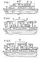
- Fig. 1 is a cross-sectional diagram of a portion of a substrate during fabrication of a charge coupled device, thereon showing a poly-Si-1 electrode formed on the device.
- Fig. 2 illustrates a subsequent step in the fabrication of the device of Fig. 1, following deposition of poly-si-2 and poly-si-3 gate structures.
- Fig. 3 illustrates a subsequent step in the processing of the device of Fig. 2, following removal of SiO₂ shield layers.
- Fig. 4 shows a later step in the fabrication of the device of Fig. 3, following etching away of the overlapping portions of the poly-Si-2 and poly-Si-3 electrodes, to produce the final, nonoverlapping gate structure.
- Fig. 5 is a cross-sectional diagram of an alternative embodiment of the invention corresponding to the stage of fabrication illustrated in Fig. 3.
- In the folllowing description, various abbreviations are used that are recognized by those skilled in the art of fabrication of charge coupled devices (CCDs). Examples of abbreviations used include the term poly-Si-1 to indicate the first-applied gate electrode, thermal SiO₂ for thermally grown silicon dioxide, CVD SiO₂ for a chemical vapor deposited silicon dioxide, etc. Although the invention is preferably carried out employing the specific combination of materials disclosed herein, persons skilled in the art will recognize that alternative materials can be used, with appropriate choices of etchants and patterning procedures, while employing the principles of the invention disclosed herein. Also, to aid in understanding how to make and use the invention, illustrative dimensions are included in the description. These dimensions are all approximate within the tolerances conventionally attainable by those skilled in the art using conventional processing apparatus, and are included merely by way of example and not of limitation.
- Referring to Fig. 1, a
silicon substrate 10 having aplanar reference surface 12 is provided. The substrate can have an epitaxial silicon surface layer, or a silicon wafer can be used. The substrate is masked and ion implanted in accordance with conventional techniques to form CCD storage regions, such asregion 14, within the substrate. These steps, being generally known in the art and forming no part of the invention except that the gate structure formed by the invention is aligned with such regions, are not further described. - The gate oxide layer 16 (400Å-1,200Å) is grown atop the substrate. This step is followed by a chemical vapor deposition of a nitride (Si₃N₄) layer 18 (400Å-1,000Å). Optionally, the surface of
layer 18 is oxidized to provide a nitride oxide (SiOxNy) layer 20 (75Å-100Å). The gate structure of the invention is then constructed atop the resultant surface 12a. - First, poly-Si-1 electrode layer 22a is deposited (4,000Å-8,000Å) atop surface 12a and oxidized to provide a covering SiO₂ layer 24a (400Å-1,000Å). Next, a nitride (Si₃N₄) layer 26a is deposited (600Å-1,200Å). Finally, a SiO₂ layer 28a is chemical vapor deposited to provide a first shield layer (8,000Å-12,000Å) over the poly-Si-1 layer. The CVD SiO₂ layer 28a is densified by annealing.
- Next is the first polysilicon gate photolithography step, to form the poly-Si-1
gate electrodes 22, one of which is shown in Fig. 1. As illustrated and described in connection with subsequent figures, three separate sets of gates are produced by this process. Accordingly, the first photolithography step includes masking a predetermined gate width at intervals of three gate widths. Only one such poly-Si-1 gate electrode is shown in the figures, but it will be understood that additional such poly-Si-1gates electrodes 22 are used, spaced out of the views in the Figures. - After masking and developing the intermediate gate structure shown in Fig. 1 is produced by four successive etching steps. The first etching step employs a buffered HF (hydrofluoric) etch to remove the unmasked portions of CVD SiO₂ layer 28a to produce
shield 28, with parallel,opposite sidewalls 29. Next, layer 26a is plasma etched using a gas such as Freon, that leaves the photoresist layer (not shown) intact atopshield 28. This is followed by a second HF etch topattern SiO₂ layer 24.Layers layer 28. Then, layer 22a is plasma etched to produce the poly-Si-1gate electrode 22. - Next follows a thermal oxidation step to oxidize the sidewalls of poly-Si-1
layer 22 to provide a dielectric (SiO₂) layer 30 (700Å-1,000Å) thereon. This step completes the procedure of forming the first set of polysilicon gate electrodes. - Referring to Fig. 2, the above-described steps of polysilicon deposition, thermal oxidation, nitride deposition, CVD SiO₂ deposition and annealing steps are repeated. The resultant layers are patterned and selectively etched in accordance with the previously described procedures to produce a poly-Si-2
gate electrode 32, covered in turn by anSiO₂ layer 34,nitride layer 36 and a densifiedCVD SiO₂ layer 38. The poly-Si-2 layer is positioned to one side of the poly-Si-1 layer, abutting againstdielectric layer 30, and is sized to overlap one side of the poly-Si-1 layer and its shield andprotective layers reference numeral 32a. A thermal oxidation step provides SiO₂ dielectric layers 40 on the sidewalls of the poly-Si-2 layer. - The procedure described in the preceding paragraph is again repeated, except for the omission of the CVD SiO₂ deposition and annealing steps, to provide poly-Si-3
gate electrodes Electrode 42 has an overlappingportion 42a which overlaps one side of the poly-Si-2 electrode and its protective and shield layers 32, 34, 36 at a position remote from the poly-Si-1 electrode.Electrode 43 has an overlappingportion 43a which overlaps one side of the poly-Si-1electrode 22 and its coveringlayers separate electrodes openings - Referring to Fig. 3, the CVD SiO₂ layers 28, 38 are selectively HF etched (10((NH₄)₂F):HF) to remove the entirety of material of the shield layers 28, 38. This step undercuts the overlapping
portions passageways undersurfaces - Next is a wet chemical etching step, which can use any of the available wet chemical silicon etchants, e.g., EDC etch. When the CVD SiO₂ shield layers 28, 38 are originally deposited, they are deposited to a sufficient thickness (8,000Å-12,000Å) to provide
passageways portions - Fig. 4 shows the structure of Fig. 3 following the last described etching step and two additional steps: first, plasma etching to remove the nitride layers 24, 34, 44 and, second, thermal oxidation to grow a thermal oxide layer 60 (2,000Å) on the upper surface of the gate electrodes. Next, the device is patterned and implanted to dope the source, drain and gate contacts, annealed and further processed in accordance with conventional procedures to complete the device.
- In the above-described embodiment of the process of the invention, nitride layers 24, 34, 44 serve to shield the polysilicon gate electrodes during removal of the overlapping portions of the poly-Si-2 and poly-Si-3 electrodes. A second embodiment of the process, illustrated in Fig. 5, omits the use of such protective layers. Instead, during the polysilicon deposition steps, the polysilicon layers 122, 132, 142, 143, corresponding to the
layers passages - The foregoing procedure provides a substantially planar, self aligned, nonoverlapping gate structure. Inter-contact shorting is reduced with concomitant improvements in yield of operative devices sufficent to make possible wafer-scale integrated CCDs. Such result is attributable to elimination of the overlapping gate structures, separated by relatively thin dielectric layers, as used in prior devices, and may be aided by the fact that the uppermost ends of the dielectric sidewall layers 30, 40, which insulatively separate the gate electrodes, are cleansed of potentially semiconductive polysilicon material by the successive plasma and chemical etch and final thermal oxidation steps at the upper surface of the contacts.
- Having illustrated and described the principles of our invention in two alternative embodiments and variations thereof, it should be apparent that the invention may be modified in arrangement and detail without departing from the principles thereof. We claim all modifications coming within the spirit and scope of the following claims.
Claims (16)
forming a poly-Si-1 electrode on the substrate surface, a first SiO₂ shield layer atop the electrode, and SiO₂ sidewalls on opposite sides of the electrode;
forming a poly-Si-2 electrode on the substrate surface on one side of the poly-Si-1 electrode and overlapping a predetermined portion of the first shield layer, a second SiO₂ layer atop the poly-Si-2 electrode, and SiO₂ sidewalls on opposite sides of the poly-Si-2 electrode;
forming two poly-Si-3 electrodes on the substrate surface, along opposite sides of the first and second shield layers of the poly-Si-1 and poly-Si-2 electrodes and overlapping said opposite sides, so as to provide four electrodes spaced side by side along the substrate surface and separated by the SiO₂ sidewalls;
removing the shield layers to form passageways exposing overlapping portions of the poly-Si-2 and poly-Si-3 electrodes; and
etching away said overlapping portions of the poly-Si-2 and poly-Si-3 electrodes, the SiO₂ shield layers being formed with a predetermined thickness such that, upon removal, the passageways can readily circulate a polysilicon etchant into contact with said overlapping portions.
depositing a first conductive gate layer on the reference surface of the substrate;
depositing a first shield layer atop the conductive gate layer;
patterning and etching the first shield and gate layers, using first and second etchants, in turn, for selectively etching first predetermined portions of the first shield and gate layers to form exposed sidewalls on the layers, the sidewall of the gate layer extending between the shield layer and the reference surface and a first adjoining portion of the reference surface being thereby exposed;
forming a first dielectric layer on the sidewall of the first gate layer;
depositing a second conductive gate layer over the reference surface and the first gate, shield and dielectric layers;
forming an opening through the second gate layer to expose a portion of the surface of the shield layer;
using said first etchant, selectively etching through said opening to remove the shield layer between the first and second conductive gate layers to undercut a portion of the second conductive gate layer and to expose a sidewall portion thereof upwardly adjacent the dielectric layer; and
subsequently, using said second etchant, selectively etching away the undercut and sidewall portions of the second gate layers so as to produce a nonoverlap ping arrangement of the first and second gate layers insulatively spaced apart by said dielectric layer.
depositing a second shield layer atop the second conductive gate layer;
patterning and etching second predetermined portions of the second gate and shield layers, using said first and second etchants in turn, to form sidewalls on the second layers, the sidewall of the second gate layer extending between the second shield layer and the reference surface, and to expose a second, adjoining portion of the reference surface at a position spaced apart from the first conductive layer by a remaining portion of the second layer;
forming a second dielectric layer on the sidewall of the second gate layer; and
depositing a third conductive gate layer over the exposed second portion of the substrate reference surface and the second shield layer;
the step of forming an opening including exposing the second shield layer over a portion of the remaining second gate layer so that the step of selectively etching through the opening using said first etchant also removes the second shield layer to undercut and expose a portion of the third gate layer upwardly adjacent the second dielectric layer for subsequently selectively etching away using the second etchant.
depositing the gate layers to a first predetermined thickness;
exposing an upper surface of the second gate layer opposite said undercut and exposed sidewall portions; and
etching the second gate layer at both the upper surface and the undercut and exposed sidewall portions to remove the layer therebetween while leaving a second predetermined thickness of the second gate layer on the reference surface.
providing a plasma-etch resistant layer on the reference surface to define a second reference surface,
depositing a first layer of plasma-etchable, polysilicon material on the plasma etch-resistant layer;
depositing a first shield layer atop an upper surface of the polysilicon layer, the shield layer being composed of a nonoxidizable, chemically-etchable material;
patterning and etching the shield and polysilicon layers in turn to form a first polysilicon gate contact and an adjacent second gate contact opening, the first contact having an exposed sidewall intersecting the second reference surface and defining a boundary of the second gate contact opening;
oxidizing the exposed sidewall of the first polysilicon gate contact to form thereon a dielectric sidewall layer of predetermined thickness spacing the first gate contact from the boundary of the second gate contact opening, the shield layer shielding the upper surface of the polysilicon gate contact from oxidation;
depositing a second layer of said polysilicon material so as to cover contiguously the oxidized layer in the second gate contact opening and the dielectric sidewall layer while leaving an upper surface portion of the shield layer exposed;
selectively etching the shield layer to remove the material thereof and from a passageway exposing an undersurface portion of the second polysilicon layer extending above the first polysilicon layer; and
selectively etching the exposed portion of the second polysilicon layer through said passageway to remove said portion.
Applications Claiming Priority (2)
| Application Number | Priority Date | Filing Date | Title |
|---|---|---|---|
| US06/866,423 US4677737A (en) | 1986-05-23 | 1986-05-23 | Self aligned zero overlap charge coupled device |
| US866423 | 1986-05-23 |
Publications (2)
| Publication Number | Publication Date |
|---|---|
| EP0246555A2 true EP0246555A2 (en) | 1987-11-25 |
| EP0246555A3 EP0246555A3 (en) | 1989-05-03 |
Family
ID=25347582
Family Applications (1)
| Application Number | Title | Priority Date | Filing Date |
|---|---|---|---|
| EP87106938A Withdrawn EP0246555A3 (en) | 1986-05-23 | 1987-05-13 | Self aligned zero overlap charge coupled device |
Country Status (3)
| Country | Link |
|---|---|
| US (1) | US4677737A (en) |
| EP (1) | EP0246555A3 (en) |
| JP (1) | JPH0656858B2 (en) |
Cited By (2)
| Publication number | Priority date | Publication date | Assignee | Title |
|---|---|---|---|---|
| EP0570090A1 (en) * | 1992-05-11 | 1993-11-18 | Samsung Electronics Co., Ltd. | Image sensor and manufacturing method thereof |
| EP0652589A1 (en) * | 1993-11-10 | 1995-05-10 | Koninklijke Philips Electronics N.V. | Method of manufacturing a semiconductor device comprising two coplanar electrical conductors separated by a dielectric layer and semiconductor device obtained by suel a method |
Families Citing this family (4)
| Publication number | Priority date | Publication date | Assignee | Title |
|---|---|---|---|---|
| US6573541B1 (en) | 2000-09-29 | 2003-06-03 | International Business Machines Corporation | Charge coupled device with channel well |
| US6998657B2 (en) * | 2003-10-21 | 2006-02-14 | Micron Technology, Inc. | Single poly CMOS imager |
| JP2007201320A (en) * | 2006-01-30 | 2007-08-09 | Matsushita Electric Ind Co Ltd | Solid-state image pickup device and manufacturing method thereof |
| JP2007201319A (en) * | 2006-01-30 | 2007-08-09 | Matsushita Electric Ind Co Ltd | Solid-state image pickup device and manufacturing method thereof |
Citations (8)
| Publication number | Priority date | Publication date | Assignee | Title |
|---|---|---|---|---|
| GB2052858A (en) * | 1979-05-18 | 1981-01-28 | Matsushita Electronics Corp | Method of making field effect transistors with short gates |
| EP0026376A2 (en) * | 1979-09-28 | 1981-04-08 | Siemens Aktiengesellschaft | Method of making integrated semiconductor circuits, particularly CCD circuits with self-aligned, non-overlapping polysilicon electrodes |
| EP0026386A2 (en) * | 1979-09-28 | 1981-04-08 | Siemens Aktiengesellschaft | Method of making integrated semiconductor circuits, particularly CCD circuits, with self-aligned, non-overlapping polysilicon electrodes |
| US4319261A (en) * | 1980-05-08 | 1982-03-09 | Westinghouse Electric Corp. | Self-aligned, field aiding double polysilicon CCD electrode structure |
| US4402188A (en) * | 1979-07-11 | 1983-09-06 | Skala Stephen F | Nested thermal reservoirs with heat pumping therebetween |
| US4461070A (en) * | 1982-05-28 | 1984-07-24 | General Electric Company | Method for making eutectic charge-coupled devices |
| EP0158371A1 (en) * | 1984-01-25 | 1985-10-16 | Koninklijke Philips Electronics N.V. | Method of manufacturing a semiconductor device and device manufactured by the use of the method |
| EP0209425A1 (en) * | 1985-06-18 | 1987-01-21 | Thomson-Csf | Method for producing a semiconductor device with several levels of gates |
Family Cites Families (5)
| Publication number | Priority date | Publication date | Assignee | Title |
|---|---|---|---|---|
| US4077112A (en) * | 1974-09-24 | 1978-03-07 | U.S. Philips Corporation | Method of manufacturing charge transfer device |
| GB1545208A (en) * | 1975-09-27 | 1979-05-02 | Plessey Co Ltd | Electrical solid state devices |
| GB2043336B (en) * | 1979-02-19 | 1983-02-09 | Philips Electronic Associated | Charge-coupled devices |
| US4402128A (en) * | 1981-07-20 | 1983-09-06 | Rca Corporation | Method of forming closely spaced lines or contacts in semiconductor devices |
| US4614564A (en) * | 1984-12-04 | 1986-09-30 | The United States Of America As Represented By The United States Department Of Energy | Process for selectively patterning epitaxial film growth on a semiconductor substrate |
-
1986
- 1986-05-23 US US06/866,423 patent/US4677737A/en not_active Expired - Lifetime
-
1987
- 1987-05-13 EP EP87106938A patent/EP0246555A3/en not_active Withdrawn
- 1987-05-20 JP JP62123622A patent/JPH0656858B2/en not_active Expired - Lifetime
Patent Citations (8)
| Publication number | Priority date | Publication date | Assignee | Title |
|---|---|---|---|---|
| GB2052858A (en) * | 1979-05-18 | 1981-01-28 | Matsushita Electronics Corp | Method of making field effect transistors with short gates |
| US4402188A (en) * | 1979-07-11 | 1983-09-06 | Skala Stephen F | Nested thermal reservoirs with heat pumping therebetween |
| EP0026376A2 (en) * | 1979-09-28 | 1981-04-08 | Siemens Aktiengesellschaft | Method of making integrated semiconductor circuits, particularly CCD circuits with self-aligned, non-overlapping polysilicon electrodes |
| EP0026386A2 (en) * | 1979-09-28 | 1981-04-08 | Siemens Aktiengesellschaft | Method of making integrated semiconductor circuits, particularly CCD circuits, with self-aligned, non-overlapping polysilicon electrodes |
| US4319261A (en) * | 1980-05-08 | 1982-03-09 | Westinghouse Electric Corp. | Self-aligned, field aiding double polysilicon CCD electrode structure |
| US4461070A (en) * | 1982-05-28 | 1984-07-24 | General Electric Company | Method for making eutectic charge-coupled devices |
| EP0158371A1 (en) * | 1984-01-25 | 1985-10-16 | Koninklijke Philips Electronics N.V. | Method of manufacturing a semiconductor device and device manufactured by the use of the method |
| EP0209425A1 (en) * | 1985-06-18 | 1987-01-21 | Thomson-Csf | Method for producing a semiconductor device with several levels of gates |
Non-Patent Citations (1)
| Title |
|---|
| IBM TECHNICAL DISCLOSURE BULLETIN vol. 24, no. 2, July 1981, pages 1273-1276, Armonk, New York, US; P. GARBARINO et al.: ""Contact first fet technology" *figures 1,2; pages 1273 - 1275* * |
Cited By (3)
| Publication number | Priority date | Publication date | Assignee | Title |
|---|---|---|---|---|
| EP0570090A1 (en) * | 1992-05-11 | 1993-11-18 | Samsung Electronics Co., Ltd. | Image sensor and manufacturing method thereof |
| EP0652589A1 (en) * | 1993-11-10 | 1995-05-10 | Koninklijke Philips Electronics N.V. | Method of manufacturing a semiconductor device comprising two coplanar electrical conductors separated by a dielectric layer and semiconductor device obtained by suel a method |
| BE1007768A3 (en) * | 1993-11-10 | 1995-10-17 | Philips Electronics Nv | Process for the manufacture of a semiconductor device and semiconductor device obtained with such a method. |
Also Published As
| Publication number | Publication date |
|---|---|
| JPH0656858B2 (en) | 1994-07-27 |
| EP0246555A3 (en) | 1989-05-03 |
| JPS62286280A (en) | 1987-12-12 |
| US4677737A (en) | 1987-07-07 |
Similar Documents
| Publication | Publication Date | Title |
|---|---|---|
| US5502009A (en) | Method for fabricating gate oxide layers of different thicknesses | |
| US5444021A (en) | Method for making a contact hole of a semiconductor device | |
| US5834816A (en) | MOSFET having tapered gate electrode | |
| KR100273070B1 (en) | Semiconductor device and method of manufacturing such a semiconductor device | |
| US4754311A (en) | Semiconductor device with contacts to parallel electrode strips | |
| JPS5836508B2 (en) | Manufacturing method of semiconductor device | |
| EP0246555A2 (en) | Self aligned zero overlap charge coupled device | |
| US6114217A (en) | Method for forming isolation trenches on a semiconductor substrate | |
| US5620911A (en) | Method for fabricating a metal field effect transistor having a recessed gate | |
| KR0183718B1 (en) | Method of manufacturing semiconductor device | |
| KR100214534B1 (en) | Method of forming a device isolation structure of semiconductor device | |
| JP2971085B2 (en) | Method for manufacturing semiconductor device | |
| KR100313543B1 (en) | Manufacturing method for flat rom | |
| KR100245075B1 (en) | Method of forming an element field oxide film in a semiconductor device | |
| KR0123782B1 (en) | Eprom semiconductor device and fabricating method thereof | |
| JPS58171864A (en) | Semiconductor device | |
| KR0172268B1 (en) | Method of manufacturing semiconductor device | |
| KR0166504B1 (en) | Method of forming a contact hall of semiconductor device | |
| KR100338095B1 (en) | Method for forming contact hole in semiconductor device | |
| KR100478495B1 (en) | Semiconductor device and fabricating method thereof | |
| KR950007422B1 (en) | Semiconductor device isolation method | |
| KR100258857B1 (en) | Manufacturing method for isolation structure of semiconductor device | |
| KR100261993B1 (en) | Manufacturing method of a capacitor using metal lines | |
| KR100257081B1 (en) | Method of forming wiring in semiconductor device using oxidation of polysilicon | |
| KR0167260B1 (en) | Manufacture of semiconductor device |
Legal Events
| Date | Code | Title | Description |
|---|---|---|---|
| PUAI | Public reference made under article 153(3) epc to a published international application that has entered the european phase |
Free format text: ORIGINAL CODE: 0009012 |
|
| AK | Designated contracting states |
Kind code of ref document: A2 Designated state(s): DE FR GB NL |
|
| PUAL | Search report despatched |
Free format text: ORIGINAL CODE: 0009013 |
|
| AK | Designated contracting states |
Kind code of ref document: A3 Designated state(s): DE FR GB NL |
|
| 17P | Request for examination filed |
Effective date: 19891031 |
|
| 17Q | First examination report despatched |
Effective date: 19910613 |
|
| STAA | Information on the status of an ep patent application or granted ep patent |
Free format text: STATUS: THE APPLICATION IS DEEMED TO BE WITHDRAWN |
|
| 18D | Application deemed to be withdrawn |
Effective date: 19911024 |
|
| RIN1 | Information on inventor provided before grant (corrected) |
Inventor name: BENN, PAULINE Inventor name: CORRIE, BRIAN L. Inventor name: MCELEVEY, MICHAEL J. |