EP0245196A2 - Method for data transmission between a fixed part and a mobile part - Google Patents
Method for data transmission between a fixed part and a mobile part Download PDFInfo
- Publication number
- EP0245196A2 EP0245196A2 EP87730045A EP87730045A EP0245196A2 EP 0245196 A2 EP0245196 A2 EP 0245196A2 EP 87730045 A EP87730045 A EP 87730045A EP 87730045 A EP87730045 A EP 87730045A EP 0245196 A2 EP0245196 A2 EP 0245196A2
- Authority
- EP
- European Patent Office
- Prior art keywords
- stationary part
- frequency
- low
- oscillator
- transmitted
- Prior art date
- Legal status (The legal status is an assumption and is not a legal conclusion. Google has not performed a legal analysis and makes no representation as to the accuracy of the status listed.)
- Granted
Links
- 230000005540 biological transmission Effects 0.000 title claims abstract description 5
- 230000010355 oscillation Effects 0.000 claims abstract description 11
- 230000001360 synchronised effect Effects 0.000 claims abstract description 8
- 230000002457 bidirectional effect Effects 0.000 claims abstract description 3
- 239000003990 capacitor Substances 0.000 claims description 3
- 230000002123 temporal effect Effects 0.000 claims 1
- 238000010586 diagram Methods 0.000 description 7
- 230000015654 memory Effects 0.000 description 6
- 230000010363 phase shift Effects 0.000 description 5
- 230000008054 signal transmission Effects 0.000 description 3
- 239000000969 carrier Substances 0.000 description 1
- 230000008878 coupling Effects 0.000 description 1
- 238000010168 coupling process Methods 0.000 description 1
- 238000005859 coupling reaction Methods 0.000 description 1
- 238000001514 detection method Methods 0.000 description 1
- 230000007613 environmental effect Effects 0.000 description 1
- 238000011156 evaluation Methods 0.000 description 1
- 230000006870 function Effects 0.000 description 1
- 230000001939 inductive effect Effects 0.000 description 1
- 230000010354 integration Effects 0.000 description 1
- 230000001502 supplementing effect Effects 0.000 description 1
Images


Classifications
-
- H04B5/266—
-
- G—PHYSICS
- G06—COMPUTING; CALCULATING OR COUNTING
- G06K—GRAPHICAL DATA READING; PRESENTATION OF DATA; RECORD CARRIERS; HANDLING RECORD CARRIERS
- G06K7/00—Methods or arrangements for sensing record carriers, e.g. for reading patterns
- G06K7/0008—General problems related to the reading of electronic memory record carriers, independent of its reading method, e.g. power transfer
-
- H—ELECTRICITY
- H04—ELECTRIC COMMUNICATION TECHNIQUE
- H04L—TRANSMISSION OF DIGITAL INFORMATION, e.g. TELEGRAPHIC COMMUNICATION
- H04L27/00—Modulated-carrier systems
- H04L27/18—Phase-modulated carrier systems, i.e. using phase-shift keying
- H04L27/22—Demodulator circuits; Receiver circuits
- H04L27/233—Demodulator circuits; Receiver circuits using non-coherent demodulation
- H04L27/2335—Demodulator circuits; Receiver circuits using non-coherent demodulation using temporal properties of the received signal
- H04L27/2337—Demodulator circuits; Receiver circuits using non-coherent demodulation using temporal properties of the received signal using digital techniques to measure the time between zero-crossings
Abstract
Diese Erfindung erweitert Schaltungen, die nach dem Prinzip des Svnchronschalters arbeiten, derart, dass eine bidirektionale Datenübertragung möglich ist, ohne dass zusätzliche Spulen benötigt werden. Durch das Anlegen von Daten an der Datenleitung beim vorwiegend stationären Teil, wird ein Phasensprung einer Schwingung fx erzeugt, welcher bei Schaltungen, die nach dem Prinzip des Synchronschalters arbeiten, zum vorwiegend beweglichen Teil übertragen wird. Aufgrund des Wechselspannungsanteiles der Schwingung fx bildet das vorwiegend bewegliche Teil Rechteckimpulse, so dass nur, wenn ein Phasensprung vorliegt, sich unterschiedliche Low- und High-Signale ergeben. Während der High- und Low-Signale werden die positiven Flanken einer festschwingenden Frequenz gezählt und miteinander verglichen. Da ein Phasensprung eine Zustandsänderung der Datenleitung beim vorwie gend stationären Teil als Ursache hat, ist mit dem Phasensprung auch die Zustandsänderung der Datenleitung erkannt.This invention extends circuits which operate on the principle of the synchronous switch in such a way that bidirectional data transmission is possible without the need for additional coils. By applying data to the data line in the predominantly stationary part, a phase jump of an oscillation fx is generated which is transmitted to the predominantly movable part in circuits which operate on the principle of the synchronous switch. Due to the alternating voltage component of the oscillation fx, the predominantly movable part forms square-wave pulses, so that different low and high signals only result when there is a phase jump. During the high and low signals, the positive edges of a fixed frequency are counted and compared with each other. Since a phase change is caused by a change in state of the data line in the predominantly stationary part, the change in state of the data line is also recognized with the phase change.
Description
Es besteht das Problem, im Bereich miniaturisierter Schaltungsträger, wie Schlüssel und Chipkarte (Scheckkarte), Signale von einer Schaltung eines ersten Teiles zu einer Schaltung eines zweiten Teiles und umgekehrt zu übertragen, wobei das erste Teil das zweite Teil auch während der Signalübertragung mit Energie versorgt und sowohl zur bidirektionalen Signalübertragung sowie zur Energieversorgung nur eine Spule, jeweils auf dem ersten Teil und eine Spule auf dem zweiten Teil, benutzt wird. Dies Problem soll durch die erfindungsgemäßen Ansprüche gelöst werden.There is the problem in the area of miniaturized circuit carriers such as keys and chip cards (check cards) to transmit signals from a circuit of a first part to a circuit of a second part and vice versa, the first part also supplying the second part with energy during the signal transmission and only one coil, each on the first part and one coil on the second part, is used both for bidirectional signal transmission and for energy supply. This problem is to be solved by the claims according to the invention.
Das Problem der monodirektionalen Signalübertragung ist durch Verwendung und Einsatz von Schaltungen nach dem Prinzip des Synchronschalters gelöst. Hierbei werden vorwiegend von einem beweglichen Teil, wie Schlüssel oder Chipkarte, zu bestimmten Zeitpunkten, welche durch Zählung von Schwingungshalbwellen markiert werden, Signale per Kurzschluß einer Spule übertragen. Solche Systeme finden bereits Anwendung im Schloß- und Schlüsselbereich.The problem of monodirectional signal transmission is solved by using and using circuits based on the principle of the synchronous switch. In this case, signals from a moving part, such as a key or chip card, are transmitted at certain points in time, which are marked by counting oscillation half-waves, by short-circuiting a coil. Such systems are already used in the lock and key area.
Der Erfindung liegt nun die Aufgabe zugrunde diese Systeme derart zu ergänzen, daß Signale vom vorwiegend stationären Teil zum beweglichen Teil (z.B. vom Schloß zum Schlüssel) nach dem Prinzip des Phasensprunges übertragen werden können, ohne daß eine zusätzliche Spule zum Einsatz kommt und auch der geometrische, äußere Aufbau der Übertragungsbauteile gleich bleibt und bestehende Empfangselektroniken nach dem Prinzip des Synchronschalters weiterhin, auch bei dem Einsatz der hier beschriebenen Erfindung, voll funktionsfähig bleiben und Signale vom vorwiegend beweglichen Elektronikteil erhalten können.The invention is based on the object of supplementing these systems in such a way that signals can be transmitted from the predominantly stationary part to the movable part (for example from the lock to the key) according to the principle of the phase jump, without an additional coil being used and also the geometric one , External structure of the transmission components remains the same and existing receiving electronics continue to function according to the principle of the synchronous switch, even when using the invention described here, and can receive signals from the predominantly movable electronic part.
Gelöst wird diese Aufgabe mit den Merkmalen im Kennzeichen des Patentanspruches.This problem is solved with the features in the characterizing part of the claim.
Neben der Integration des Synchronschalterprinzipes war es erforderlich, eine solche Auswertung eines Phasensprunges zu finden, welche per Schaltung problemlos miniaturisierbar ist und somit als IC auf einem beweglichen Träger, wie einem Schlüssel oder einer Chipkarte, unterzubringen ist. Größere Bauteile, wie Spulen oder Kondensatoren oder Widerstände, welche im Bereich digitaler Schaltungen nur schwer realisierbar sind, sollten möglichst für die Schaltung nicht benötigt werden. Auch sollte die Schaltung gegenüber Umwelteinflüssen äußerst stabil sein.In addition to the integration of the synchronous switch principle, it was necessary to find such an evaluation of a phase jump, which can be miniaturized easily by switching and can therefore be accommodated as an IC on a movable carrier, such as a key or a chip card. Larger components, such as coils or capacitors or resistors, which are difficult to implement in the field of digital circuits, should preferably not be required for the circuit. The circuit should also be extremely stable against environmental influences.
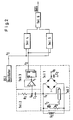
Im Bild 1 ist die Erzeugung eines Phasensprunges per EXOR Glied (EX1) dargestellt. Die Signaldaten werden vom Flipflop (FF1) mit dem Text des Oszillators (OS1) synchronisiert. Mit dem Ausgang vom EX1 ist die Basis des Transistors T1 verbunden. T1 zwingt dem Schwingkreis, bestehend aus Kondensator C1 und Spule S1, die vom Oszillator OS1 vorgegebene Frequenz auf. Über die Spule S1 besteht eine induktive Kopplung zur Spule S2 in Bild 2. Aus dieser Anordnung von Bild 1 ist ersichtlich, daß eine Zustandsänderung der Signaldatenleitung (S) eine Phasenverschiebung von 180 der Schwingung fx zur Folge hat, die über S1 auf S2 übertragen wird. In der DE-PS 31 49 789 ist dies Prinzip, ohne die Phasenverschiebung, bereits beschrieben.Figure 1 shows the generation of a phase jump using the EXOR element (EX1). The signal data are synchronized by the flip-flop (FF1) with the text of the oscillator (OS1). The base of transistor T1 is connected to the output of EX1. T1 forces the resonant circuit, consisting of capacitor C1 and coil S1, to the frequency specified by oscillator OS1. Via coil S1 there is an inductive coupling to coil S2 in Figure 2. From this arrangement in Figure 1 it can be seen that a change in state of the signal data line (S) results in a phase shift of 180 of oscillation fx, which is transmitted via S1 to S2 . In DE-PS 31 49 789 this principle is described without the phase shift.
Bild 2 zeigt das Blockschaltbild des vorwiegend beweglichen Teiles zur Erkennung des Phasensprunges und Details der Teile 1, 2 und 3. Die benötigte Betriebsspannung des vorwiegend beweglichen Teiles wird aus dem Gleichspannungsteil der von S1 nach S2 übertragenen Schwingung fx' im stationären Teil 1 gewonnen. Ferner wird z.B. über den Transistor T2 und den Widerstand R2 die Spule S2 über ein Schaltungsteil 7 zu Zeitpunkten kurzgeschlossen, welche durch Zählung von Halbwellen der Frequenz fx bestimmt ist. Im beweglichen Teil 2 wird der Wechselspannungsteil (Bild 4, Diagramm fm) der Schwingung fx' ausgefiltert. Schaltungsteil 3 bildet aus dem in Teil 2 ausgefilterten Wechselspannungsteil Rechteck-Impulse, und zwar so, daß, wenn kein Phasensprung vorliegt, die High-Signale ebenso lang sind wie die Low-Signale (Bild 4, Diagramm f2). Schaltungsteil 5 zählt die positiven Flanken der fest schwingenden Frequenz fo während das Low-Signal von f2 anliegt. Schaltungsteil 4 zählt die positiven Flanken der fest schwingenden Frequenz fo während das High-Signal von f2 anliegt. Die fest schwingende Frequenz fo wird durch den Oszillator OS2 auf dem vorwiegend beweglichen Teil erzeugt, dessen Frequenz höher ist als die des Oszillators OS1 auf dem vorwiegend stationären Teil.Figure 2 shows the block diagram of the predominantly moving part for the detection of the phase shift and details of
Schaltungsteil 6 subtrahiert die Anzahl der von den Schaltungsteilen 4 und 5 gezählten positiven Flanken voneinander. Aus der Differenz dieser Zahlen kann auf einen Phasensprung auf seiten des stationären Teiles geschlossen werden, womit der Ausgang DATA von Schaltungsteil 6 auf High gesetzt werden kann.
Schaltungsteil 3 besteht aus einem übersteuerten Operationsverstärker und einem Flipflop. Der Operationsverstärker wandelt die sinusähnliche Wechselspannung in Rechteck-Impulse um, so daß die Dauer der positiven Halbwellen der Dauer des High-Signales, die Dauer der negativen Halbwelle der Dauer des Low-Signales entspricht. Sollten jedoch, wenn kein Phasensprung vorliegt, die positive und die negative Halbwelle des Wechselspannungsteiles verschieden lang sein, würde die Schaltung zur Erkennung des Phasensprunges fälschlicherweise einen Phasensprung erkennen, wie aus obiger Beschreibung deutlich wird. Um dies zu verhindern, wird dem Operationsverstärker ein Flipflop nachgeschaltet, so daß eine Periodendauer der Schwingung fm der Dauer des High bzw. Low-Signales entspricht.
Bild 3 zeigt eine mögliche Ausgestaltung der Schaltungsteile 4, 5, 6. Die And- Gatter A und B bestimmen, wann die dahinter folgende Zählschaltung aktiviert wird. Bauelement C bildet den Betrag der Differenz der Inhalte des Datenspeichers G und H.Figure 3 shows a possible configuration of the
Bauelement D legt seinen Ausgang auf High, wenn der Betrag der Differenz größer als 1 ist. Die weitere Funktionsweise verdeutlichen die Diagramme von Bild 6.Component D sets its output to high if the magnitude of the difference is greater than 1. The diagrams in Figure 6 illustrate the further mode of operation.
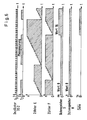
Bild 4 zeigt für den Fall, daß kein Phasensprung vorliegt, wie aus dem Wechselspannungsanteil der Schwingung fx' Rechteckimpulse zur digitalen Weiterverarbeitung werden anhand von zu Bild 2 gehörigen Diagrammen.In the event that there is no phase jump, Figure 4 shows how the alternating voltage component of the oscillation fx 'becomes rectangular pulses for further digital processing on the basis of diagrams belonging to Figure 2.
Bild 5 zeigt für den Fall, daß ein Phasensprung vorliegt, wie aus dem Wechselspannungsanteil der Schwingung fx' Rechteckimpulse zur digitalen Weiterverarbeitung werden anhand von zu Bild 2 gehörigen Diagrammen. Bild 5 macht deutlich, daß es unerheblich ist, wie sich die Schwingung beim Phasensprung verhält, da sich aufgrund der Phasenverschiebung um 180 eine unterschiedliche Dauer von High- zu Low-Signalen ergeben muß.In the event that there is a phase jump, Figure 5 shows how the alternating voltage component of the oscillation fx 'becomes rectangular pulses for digital further processing on the basis of diagrams belonging to Figure 2. Figure 5 makes it clear that it does not matter how the oscillation behaves during the phase shift, since the phase shift by 180 means that the duration of the signals must vary from high to low.
In Bild 6 sind die zu Bild 3 gehörigen Diagramme dargestellt. Liegt von f2 ein High-Signal an, so zählt der Zähler E jede positive Flanke der Frequenz des Oszillators OS2. Wechselt nun mit f2 das Signal von High auf Low, so übernimmt der Datenspeicher G mit der negativen Flanke die von E gezählten positiven Flanken und der Zähler F wird zurückgesetzt. Im Datenspeicher H ist noch die Anzahl der gezählten positiven Flanken während des vorherigen Low-Signales gespeichert. Da die Differenz der Inhalte der Datenspeicher H und G kleiner als 2 ist, ist der Ausgang von Teil 6 auf DATA = Low gesetzt. Der Zähler F zählt nun die Anzahl der positiven Flanken während des Low-Signales.Figure 6 shows the diagrams belonging to Figure 3. If there is a high signal from f2, the counter E counts each positive edge of the frequency of the oscillator OS2. If the signal changes from high to low with f2, the data memory G with the negative edge takes over the positive edges counted by E and the counter F is reset. The number of positive edges counted during the previous low signal is also stored in data memory H. Since the difference in the contents of the data memories H and G is less than 2, the output from
Wechselt f2 von Low auf High, übernimmt der Datenspeicher H mit der positiven Flanke die gezählten positiven Flanken während des Low-Signales und der Zähler E wird zurückgesetzt. Nun zählt der Zähler E wieder die positiven Flanken während des High-Signales.If f2 changes from low to high, the data memory H with the positive edge takes over the counted positive edges during the low signal and the counter E is reset. Now the counter E counts the positive edges again during the high signal.
Ändert sich das Verhältnis der Zeit von Signalzustand High zu Signalzustand Low von f2, ändert sich auch die Zahl der gezählten positiven Flanken von fo, welche in den Datenspeichern G und H gespeichert sind. Der Komperator (Schaltungsteil G) vergleicht die in G und H gespeicherten Zahlen und gibt das Signal DATA (gemäß Bild :3 und Bild G) ab.If the ratio of the time from signal state high to signal state low changes from f2, the number of counted positive edges of fo, which are stored in the data memories G and H, also changes. The comparator (circuit part G) compares the numbers stored in G and H and outputs the signal DATA (according to Fig. 3 and Fig. G).
Gemäß Bild 5 und obiger Beschreibung tritt ein solcher Zeitunterschied zwischen Signalzustand High von f2 und Signalzustand Low von f2 mit der Erzeugung eines Phasensprunges auf, der somit eindeutig durch das Signal DATA indiziert wird.As shown in Figure 5 and the description above, such a time difference occurs between signal state High of f2 and signal state Low of f2 with the generation of a phase jump, which is thus clearly indicated by the DATA signal.
Wie aus dieser Beschreibung ersichtlich wird, erfüllt die Schaltung die eingangs aufgestellten Forderungen. Der Schaltungsmehraufwand bei Schaltungen, die nach dem Prinzip des Synchronschalters arbeiten, ist begrenzt und fast ausschließlich digital und somit problemlos miniaturisierbar.As can be seen from this description, the circuit fulfills the requirements set out at the beginning. The additional circuitry for circuits that work according to the principle of the synchronous switch is limited and almost exclusively digital and therefore can be miniaturized without problems.
Claims (1)
dadurch gekennzeichnet,
daß auf dem beweglichen Teil aus der vom stationären Teil übertragenen Schwingung, der zu bestimmten Zeitpunkten vom stationären Teil Phasensprünge aufgezwungen werden können, Rechteckimpulse erzeugt werden, deren zeitliches Verhältnis der Dauer von High-Zustand zu Low-Zustand konstant ist, indem der Frequenzanteil der übertragenen Schwingung über einen Kondensator vom Gleichspannungsanteil getrennt wird, wobei ein Gleichspannungsteil aus der übertragenen Schwingung zur Versorgung der Schaltung des beweglichen Teiles gewonnen wird und indem die derart gewonnene Frequenz einem übersteuerten Operationsverstärker mit nachgeschaltetem Flip-Flop zugeführt wird und daß die derart erzeugten Rechteckimpulse konstante Zeitverhältnisse zwischen High- und Low-Zuständen haben, sofern der vom stationären Teil übertragenen Schwingung keine Phasensprünge aufgezwungen wurden, wobei auch ein Oszillator auf dem beweglichen Teil enthalten ist, welcher eine Schwingung mit einer wesentlich höheren Frequenz als der Oszillator vom stationären Teil erzeugt und daß'ferner die High-Zeiten der Rechteckimpulse, welche aus der übertragenen Frequenz des Oszillators vom stationären Teil gewonnen wurden, mit den Low-zeiten dieser Rechteckimpulse verglichen werden, indem die Frequenz des Oszillators des beweglichen Teiles laufend während der High- und Low-Zeiten der aus der übertragenen Frequenz des Oszillators vom stationären Teil gewonnenen Rechteckimpulse gezält werden und die Zählung der Frequenzdurchgänge einer High-zeit zu einer unmittelbar folgenden Low-Zeit der Rechteckimpulse oder die Zählung der Frequenzdurchgänge der Low-Zeit zu einer unmittelbar folgenden High-Zeit zu Unterschieden in der Zahl der Zählung führen, wenn infolge eines Phasensprunges in der Schwindung des stationären Teiles die High- zu den Low-Zeiten der auf dem beweglichen Teil gewonnenen Rechteckimpulse ihre Zeitanteile ändern, womit in einem digitalen Vergleich der Zählwerte bei Abweichung der auf dem stationären Teil erzeugte Phasensprung vom beweglichen Teil nachgewiesen wird.Device for bidirectional data transmission between a predominantly stationary part and a predominantly moving part, the stationary part containing an oscillator and transmitting power to the moving part during the total time of the data transmission according to the transformer principle, and the moving part and the stationary part in each case only one coil have, and furthermore the movable part transmits signals to the stationary part according to the principle of the synchronous switch,
characterized,
that rectangular pulses are generated on the movable part from the oscillation transmitted by the stationary part, which can be forced at certain points in time by the stationary part, whose temporal ratio of the duration from high state to low state is constant by the frequency component of the transmitted part Vibration is separated from the DC voltage component via a capacitor, a DC voltage part being obtained from the transmitted vibration for supplying the circuit of the movable part and by the frequency obtained in this way being fed to an overdriven operational amplifier with a downstream flip-flop, and in that the square-wave pulses generated in this way have constant time ratios between High and low states have been provided that no phase jumps were imposed on the oscillation transmitted by the stationary part, an oscillator also being included on the movable part, which oscillation has a significantly higher frequency than the oscillator generated by the stationary part and that 'er further the high times the rectangular pulses, which were obtained from the transmitted frequency of the oscillator from the stationary part, are compared with the low times of these rectangular pulses by the frequency of the oscillator of the movable part continuously during the high and low times of the transmitted frequency of the oscillator rectangular pulses obtained from the stationary part are counted and the counting of the frequency crossings of a high time leads to an immediately following low time of the rectangular pulses or the counting of the frequency crossings of the low time leads to differences immediately in the number of counting, if, due to a phase jump in the shrinkage of the stationary part, the high to low times of the rectangular pulses obtained on the moving part change their time components, whereby a digital comparison of the count values in the event of a deviation from the moving part generated on the stationary part proves the difference in time .
Priority Applications (1)
| Application Number | Priority Date | Filing Date | Title |
|---|---|---|---|
| AT87730045T ATE64801T1 (en) | 1986-04-29 | 1987-04-27 | METHOD OF DATA TRANSMISSION BETWEEN A FIXED PART AND A MOVING PART. |
Applications Claiming Priority (2)
| Application Number | Priority Date | Filing Date | Title |
|---|---|---|---|
| DE19863614477 DE3614477A1 (en) | 1986-04-29 | 1986-04-29 | DEVICE FOR BIDIRECTIONAL DATA TRANSFER |
| DE3614477 | 1986-04-29 |
Publications (3)
| Publication Number | Publication Date |
|---|---|
| EP0245196A2 true EP0245196A2 (en) | 1987-11-11 |
| EP0245196A3 EP0245196A3 (en) | 1988-03-16 |
| EP0245196B1 EP0245196B1 (en) | 1991-06-26 |
Family
ID=6299774
Family Applications (1)
| Application Number | Title | Priority Date | Filing Date |
|---|---|---|---|
| EP87730045A Expired - Lifetime EP0245196B1 (en) | 1986-04-29 | 1987-04-27 | Method for data transmission between a fixed part and a mobile part |
Country Status (5)
| Country | Link |
|---|---|
| US (1) | US4796028A (en) |
| EP (1) | EP0245196B1 (en) |
| JP (1) | JPS62261242A (en) |
| AT (1) | ATE64801T1 (en) |
| DE (1) | DE3614477A1 (en) |
Cited By (14)
| Publication number | Priority date | Publication date | Assignee | Title |
|---|---|---|---|---|
| DE4017934A1 (en) * | 1990-06-05 | 1992-01-02 | Josef Thomas Wanisch | Wireless signal interrogator for relay station - achieves capacitive energy and data transmission using opposite electrode pairs forming capacitors at both stations |
| EP0649110A1 (en) * | 1993-10-18 | 1995-04-19 | France Telecom | Device with spectral purity for exchanging at a distance information between a portable object and a station |
| US6018299A (en) * | 1998-06-09 | 2000-01-25 | Motorola, Inc. | Radio frequency identification tag having a printed antenna and method |
| US6040773A (en) * | 1995-10-11 | 2000-03-21 | Motorola, Inc. | Radio frequency identification tag arranged for magnetically storing tag state information |
| US6107920A (en) * | 1998-06-09 | 2000-08-22 | Motorola, Inc. | Radio frequency identification tag having an article integrated antenna |
| US6229442B1 (en) | 2000-03-14 | 2001-05-08 | Motorola, Inc, | Radio frequency identification device having displacement current control and method thereof |
| US6236316B1 (en) | 1999-01-05 | 2001-05-22 | Motorola, Inc. | Transport device with openings for capacitive coupled readers |
| US6246327B1 (en) | 1998-06-09 | 2001-06-12 | Motorola, Inc. | Radio frequency identification tag circuit chip having printed interconnection pads |
| US6252508B1 (en) | 1995-10-11 | 2001-06-26 | Motorola, Inc. | Radio frequency identification tag arranged for magnetically storing tag state information |
| US6265977B1 (en) | 1998-09-11 | 2001-07-24 | Motorola, Inc. | Radio frequency identification tag apparatus and related method |
| US6362738B1 (en) | 1998-04-16 | 2002-03-26 | Motorola, Inc. | Reader for use in a radio frequency identification system and method thereof |
| US6411213B1 (en) | 1995-10-11 | 2002-06-25 | Motorola, Inc. | Radio frequency identification tag system using tags arranged for coupling to ground |
| US6496112B1 (en) | 1998-02-27 | 2002-12-17 | Motorola, Inc. | Radio frequency identification tag with a programmable circuit state |
| US6611199B1 (en) | 1995-10-11 | 2003-08-26 | Motorola, Inc. | Capacitively powered portable communication device and associated exciter/reader and related method |
Families Citing this family (13)
| Publication number | Priority date | Publication date | Assignee | Title |
|---|---|---|---|---|
| DE3912497A1 (en) * | 1989-04-15 | 1990-10-18 | Daimler Benz Ag | SIMULTANEOUS ENERGY AND DATA RETURN TRANSFER OVER LOOSE TRANSFORMERAL COUPLING |
| ATE135835T1 (en) * | 1990-07-16 | 1996-04-15 | Siemens Ag | DEVICE FOR CONTACTLESS DATA AND ENERGY TRANSMISSION AND USE OF SUCH |
| AT395224B (en) * | 1990-08-23 | 1992-10-27 | Mikron Ges Fuer Integrierte Mi | CONTACTLESS, INDUCTIVE DATA TRANSFER SYSTEM |
| DE4038970A1 (en) * | 1990-12-06 | 1992-06-11 | Schlafhorst & Co W | METHOD AND DEVICE FOR BIDIRECTIONAL DATA TRANSMISSION BETWEEN A TEXTILE MACHINE AND A TEXTILE PRODUCT |
| DE4230148C2 (en) * | 1992-09-09 | 1994-08-25 | Angewandte Digital Elektronik | Circuit arrangement for detecting an interruption in the electrical connection of contactless chip cards to their read / write device |
| DE4240238C2 (en) * | 1992-11-30 | 1995-01-05 | Angewandte Digital Elektronik | Device for contactless energy and data transmission for single-coil and double-coil systems |
| US5736967A (en) * | 1993-09-03 | 1998-04-07 | Kayser Ventures, Ltd. | Article-information display system using electronically controlled tags |
| US6181299B1 (en) | 1993-09-03 | 2001-01-30 | Display Edge Technology, Ltd. | Power and communication system for electronic display tags |
| US6266052B1 (en) | 1993-09-03 | 2001-07-24 | Display Edge Technology, Ltd. | Power and information distribution system for article display or storage areas and related method |
| US6249263B1 (en) | 1993-09-03 | 2001-06-19 | Display Edge Technology, Ltd. | Article-information display system using electronically controlled tags |
| DE19726335C2 (en) | 1997-06-20 | 2000-03-02 | Angewandte Digital Elektronik | Chip card with at least two coil arrangements for the transmission of data and / or energy |
| DE19800565C2 (en) * | 1998-01-09 | 2000-06-29 | Siemens Ag | Data transmission system with a movable transponder and a base station |
| WO2012026343A1 (en) * | 2010-08-24 | 2012-03-01 | Semiconductor Energy Laboratory Co., Ltd. | Semiconductor device |
Citations (1)
| Publication number | Priority date | Publication date | Assignee | Title |
|---|---|---|---|---|
| DE2658499A1 (en) * | 1976-01-13 | 1977-07-14 | Asea Ab | ARRANGEMENT FOR THE CONTACTLESS TRANSMISSION OF SIGNALS BETWEEN A FIXED AND A MOVING PART OF A MACHINE |
Family Cites Families (8)
| Publication number | Priority date | Publication date | Assignee | Title |
|---|---|---|---|---|
| US3088099A (en) * | 1960-09-19 | 1963-04-30 | W W Henry Company | Data communication system |
| US3488632A (en) * | 1967-02-20 | 1970-01-06 | William T Clark | Infinitely variable inductive remote control system |
| DE3149789C1 (en) * | 1981-12-16 | 1983-08-25 | Angewandte Digital Elektronik Gmbh, 2051 Brunstorf | Device for inductive identification of an information item |
| US4549176A (en) * | 1983-04-01 | 1985-10-22 | Angewandte Digital Elektronik Gmbh | Device for identifying an information particularly an electronic lock/key combination |
| DE3402737C1 (en) * | 1984-01-27 | 1985-08-01 | Angewandte Digital Elektronik Gmbh, 2051 Brunstorf | Mutual information transmission device |
| US4654658A (en) * | 1984-08-03 | 1987-03-31 | Walton Charles A | Identification system with vector phase angle detection |
| DE3447560A1 (en) * | 1984-12-21 | 1986-07-10 | Angewandte Digital Elektronik Gmbh, 2051 Brunstorf | DEVICE FOR CONTACTLESS SIGNAL AND ENERGY TRANSMISSION |
| US4656472A (en) * | 1985-01-23 | 1987-04-07 | Walton Charles A | Proximity identification system with power aided identifier |
-
1986
- 1986-04-29 DE DE19863614477 patent/DE3614477A1/en active Granted
-
1987
- 1987-04-17 US US07/039,436 patent/US4796028A/en not_active Expired - Lifetime
- 1987-04-27 EP EP87730045A patent/EP0245196B1/en not_active Expired - Lifetime
- 1987-04-27 AT AT87730045T patent/ATE64801T1/en not_active IP Right Cessation
- 1987-04-28 JP JP62103449A patent/JPS62261242A/en active Pending
Patent Citations (1)
| Publication number | Priority date | Publication date | Assignee | Title |
|---|---|---|---|---|
| DE2658499A1 (en) * | 1976-01-13 | 1977-07-14 | Asea Ab | ARRANGEMENT FOR THE CONTACTLESS TRANSMISSION OF SIGNALS BETWEEN A FIXED AND A MOVING PART OF A MACHINE |
Non-Patent Citations (1)
| Title |
|---|
| IEEE TRANSACTIONS ON COMMUNICATIONS, Band COM-21, Nr. 12, Dezember 1973, Seiten 1352-1360, V.O. HENTINEN et al.: "A digital demodulator for PSK signals" * |
Cited By (16)
| Publication number | Priority date | Publication date | Assignee | Title |
|---|---|---|---|---|
| DE4017934A1 (en) * | 1990-06-05 | 1992-01-02 | Josef Thomas Wanisch | Wireless signal interrogator for relay station - achieves capacitive energy and data transmission using opposite electrode pairs forming capacitors at both stations |
| EP0649110A1 (en) * | 1993-10-18 | 1995-04-19 | France Telecom | Device with spectral purity for exchanging at a distance information between a portable object and a station |
| FR2711440A1 (en) * | 1993-10-18 | 1995-04-28 | France Telecom | Spectral purity device for the remote exchange of information between a portable object and a station. |
| US5734333A (en) * | 1993-10-18 | 1998-03-31 | France Telecom | Device with spectral purity for the remote exchange of information between a portable object and a station |
| US6252508B1 (en) | 1995-10-11 | 2001-06-26 | Motorola, Inc. | Radio frequency identification tag arranged for magnetically storing tag state information |
| US6040773A (en) * | 1995-10-11 | 2000-03-21 | Motorola, Inc. | Radio frequency identification tag arranged for magnetically storing tag state information |
| US6611199B1 (en) | 1995-10-11 | 2003-08-26 | Motorola, Inc. | Capacitively powered portable communication device and associated exciter/reader and related method |
| US6411213B1 (en) | 1995-10-11 | 2002-06-25 | Motorola, Inc. | Radio frequency identification tag system using tags arranged for coupling to ground |
| US6496112B1 (en) | 1998-02-27 | 2002-12-17 | Motorola, Inc. | Radio frequency identification tag with a programmable circuit state |
| US6362738B1 (en) | 1998-04-16 | 2002-03-26 | Motorola, Inc. | Reader for use in a radio frequency identification system and method thereof |
| US6018299A (en) * | 1998-06-09 | 2000-01-25 | Motorola, Inc. | Radio frequency identification tag having a printed antenna and method |
| US6246327B1 (en) | 1998-06-09 | 2001-06-12 | Motorola, Inc. | Radio frequency identification tag circuit chip having printed interconnection pads |
| US6107920A (en) * | 1998-06-09 | 2000-08-22 | Motorola, Inc. | Radio frequency identification tag having an article integrated antenna |
| US6265977B1 (en) | 1998-09-11 | 2001-07-24 | Motorola, Inc. | Radio frequency identification tag apparatus and related method |
| US6236316B1 (en) | 1999-01-05 | 2001-05-22 | Motorola, Inc. | Transport device with openings for capacitive coupled readers |
| US6229442B1 (en) | 2000-03-14 | 2001-05-08 | Motorola, Inc, | Radio frequency identification device having displacement current control and method thereof |
Also Published As
| Publication number | Publication date |
|---|---|
| DE3614477C2 (en) | 1988-05-05 |
| EP0245196A3 (en) | 1988-03-16 |
| US4796028A (en) | 1989-01-03 |
| EP0245196B1 (en) | 1991-06-26 |
| DE3614477A1 (en) | 1987-11-05 |
| JPS62261242A (en) | 1987-11-13 |
| ATE64801T1 (en) | 1991-07-15 |
Similar Documents
| Publication | Publication Date | Title |
|---|---|---|
| EP0245196B1 (en) | Method for data transmission between a fixed part and a mobile part | |
| DE3810702C2 (en) | ||
| DE2748584C2 (en) | Portable detection wafer for an identification device | |
| EP0151087B1 (en) | Device for two-way interchange of information | |
| DE3713821C2 (en) | Isolation amplifier with exact timing of the signals coupled across the isolation barrier | |
| DE2524571C3 (en) | Homodyne transmission system with phase detector for radio location | |
| DE60203637T2 (en) | CONTACT-FREE INTEGRATED CIRCUIT WITH AUTOMATIC FRAME IDENTIFICATION AGENTS | |
| EP0191019B1 (en) | Unit for transferring binary data between a movable data medium and a fixed station | |
| DE2535410B2 (en) | Query / response system for information transmission for rail vehicles with impulse query and modulated response | |
| DE2427225A1 (en) | PROCEDURE AND CIRCUIT ARRANGEMENT FOR DEMODULATING DIGITAL INFORMATION | |
| EP1125407B1 (en) | Method for ask demodulation and ask demodulator | |
| DE3149789C1 (en) | Device for inductive identification of an information item | |
| DE1416100B2 (en) | DEVICE FOR IDENTIFYING MOVING OBJECTS USING HIGH FREQUENCY ELECTRICAL SIGNALS | |
| DE1813319B2 (en) | Identification system providing "key" - employs radiation transmitter in fixed appts and responder cct in key | |
| DE19800565C2 (en) | Data transmission system with a movable transponder and a base station | |
| DE3113800A1 (en) | FREQUENCY MODULATOR | |
| DE3832330C2 (en) | Circuit arrangement for deriving horizontal-frequency and critical-frequency pulses | |
| DE3919191A1 (en) | Two capacitance or resistance difference evaluation circuit - comprises interconnected monostable flip=flops and is used for acceleration sensor in vehicle control system | |
| DE2522441C2 (en) | Monitoring system for electronic assemblies or devices in wired telecommunications systems | |
| DE3403637A1 (en) | METHOD AND DELAY UNIT FOR GENERATING A DELAYED OUTPUT SIGNAL | |
| EP0647926B1 (en) | Device for detecting disturbances during signal transmission in motorcars | |
| DE3539491C2 (en) | ||
| DE2811753C2 (en) | Digital demodulator on semiconductor basis | |
| DE2339026C2 (en) | Method and circuit arrangement for removing parity bits from binary words | |
| EP0645915B1 (en) | Data link system |
Legal Events
| Date | Code | Title | Description |
|---|---|---|---|
| PUAI | Public reference made under article 153(3) epc to a published international application that has entered the european phase |
Free format text: ORIGINAL CODE: 0009012 |
|
| AK | Designated contracting states |
Kind code of ref document: A2 Designated state(s): AT CH FR GB IT LI NL SE |
|
| PUAL | Search report despatched |
Free format text: ORIGINAL CODE: 0009013 |
|
| AK | Designated contracting states |
Kind code of ref document: A3 Designated state(s): AT CH FR GB IT LI NL SE |
|
| 17P | Request for examination filed |
Effective date: 19880418 |
|
| 17Q | First examination report despatched |
Effective date: 19900412 |
|
| GRAA | (expected) grant |
Free format text: ORIGINAL CODE: 0009210 |
|
| AK | Designated contracting states |
Kind code of ref document: B1 Designated state(s): AT CH FR GB IT LI NL SE |
|
| PG25 | Lapsed in a contracting state [announced via postgrant information from national office to epo] |
Ref country code: SE Effective date: 19910626 |
|
| REF | Corresponds to: |
Ref document number: 64801 Country of ref document: AT Date of ref document: 19910715 Kind code of ref document: T |
|
| GBT | Gb: translation of ep patent filed (gb section 77(6)(a)/1977) | ||
| ET | Fr: translation filed | ||
| ITF | It: translation for a ep patent filed |
Owner name: STUDIO JAUMANN |
|
| PLBE | No opposition filed within time limit |
Free format text: ORIGINAL CODE: 0009261 |
|
| STAA | Information on the status of an ep patent application or granted ep patent |
Free format text: STATUS: NO OPPOSITION FILED WITHIN TIME LIMIT |
|
| 26N | No opposition filed | ||
| PGFP | Annual fee paid to national office [announced via postgrant information from national office to epo] |
Ref country code: NL Payment date: 19990429 Year of fee payment: 13 |
|
| PGFP | Annual fee paid to national office [announced via postgrant information from national office to epo] |
Ref country code: AT Payment date: 20000510 Year of fee payment: 14 |
|
| PGFP | Annual fee paid to national office [announced via postgrant information from national office to epo] |
Ref country code: GB Payment date: 20000511 Year of fee payment: 14 |
|
| PGFP | Annual fee paid to national office [announced via postgrant information from national office to epo] |
Ref country code: FR Payment date: 20000626 Year of fee payment: 14 |
|
| PGFP | Annual fee paid to national office [announced via postgrant information from national office to epo] |
Ref country code: CH Payment date: 20000628 Year of fee payment: 14 |
|
| PG25 | Lapsed in a contracting state [announced via postgrant information from national office to epo] |
Ref country code: NL Free format text: LAPSE BECAUSE OF NON-PAYMENT OF DUE FEES Effective date: 20001101 |
|
| NLV4 | Nl: lapsed or anulled due to non-payment of the annual fee |
Effective date: 20001101 |
|
| REG | Reference to a national code |
Ref country code: FR Ref legal event code: ST |
|
| PG25 | Lapsed in a contracting state [announced via postgrant information from national office to epo] |
Ref country code: GB Free format text: LAPSE BECAUSE OF NON-PAYMENT OF DUE FEES Effective date: 20010427 Ref country code: AT Free format text: LAPSE BECAUSE OF NON-PAYMENT OF DUE FEES Effective date: 20010427 |
|
| REG | Reference to a national code |
Ref country code: FR Ref legal event code: RN |
|
| PG25 | Lapsed in a contracting state [announced via postgrant information from national office to epo] |
Ref country code: LI Free format text: LAPSE BECAUSE OF NON-PAYMENT OF DUE FEES Effective date: 20010526 Ref country code: CH Free format text: LAPSE BECAUSE OF NON-PAYMENT OF DUE FEES Effective date: 20010526 |
|
| REG | Reference to a national code |
Ref country code: FR Ref legal event code: FC |
|
| REG | Reference to a national code |
Ref country code: CH Ref legal event code: PL |
|
| GBPC | Gb: european patent ceased through non-payment of renewal fee |
Effective date: 20010427 |
|
| PG25 | Lapsed in a contracting state [announced via postgrant information from national office to epo] |
Ref country code: IT Free format text: LAPSE BECAUSE OF NON-PAYMENT OF DUE FEES;WARNING: LAPSES OF ITALIAN PATENTS WITH EFFECTIVE DATE BEFORE 2007 MAY HAVE OCCURRED AT ANY TIME BEFORE 2007. THE CORRECT EFFECTIVE DATE MAY BE DIFFERENT FROM THE ONE RECORDED. Effective date: 20050427 |
|
| PG25 | Lapsed in a contracting state [announced via postgrant information from national office to epo] |
Ref country code: FR Free format text: LAPSE BECAUSE OF NON-PAYMENT OF DUE FEES Effective date: 20010430 |
|
| PGRI | Patent reinstated in contracting state [announced from national office to epo] |
Ref country code: FR Effective date: 20100326 |