EP0244769A2 - X-Ray source - Google Patents
X-Ray source Download PDFInfo
- Publication number
- EP0244769A2 EP0244769A2 EP87106299A EP87106299A EP0244769A2 EP 0244769 A2 EP0244769 A2 EP 0244769A2 EP 87106299 A EP87106299 A EP 87106299A EP 87106299 A EP87106299 A EP 87106299A EP 0244769 A2 EP0244769 A2 EP 0244769A2
- Authority
- EP
- European Patent Office
- Prior art keywords
- anode
- grid
- cathode
- ray source
- rays
- Prior art date
- Legal status (The legal status is an assumption and is not a legal conclusion. Google has not performed a legal analysis and makes no representation as to the accuracy of the status listed.)
- Withdrawn
Links
Images


Classifications
-
- G—PHYSICS
- G21—NUCLEAR PHYSICS; NUCLEAR ENGINEERING
- G21K—TECHNIQUES FOR HANDLING PARTICLES OR IONISING RADIATION NOT OTHERWISE PROVIDED FOR; IRRADIATION DEVICES; GAMMA RAY OR X-RAY MICROSCOPES
- G21K1/00—Arrangements for handling particles or ionising radiation, e.g. focusing or moderating
- G21K1/02—Arrangements for handling particles or ionising radiation, e.g. focusing or moderating using diaphragms, collimators
-
- H—ELECTRICITY
- H01—ELECTRIC ELEMENTS
- H01J—ELECTRIC DISCHARGE TUBES OR DISCHARGE LAMPS
- H01J35/00—X-ray tubes
-
- H—ELECTRICITY
- H01—ELECTRIC ELEMENTS
- H01J—ELECTRIC DISCHARGE TUBES OR DISCHARGE LAMPS
- H01J35/00—X-ray tubes
- H01J35/02—Details
- H01J35/04—Electrodes ; Mutual position thereof; Constructional adaptations therefor
-
- H—ELECTRICITY
- H01—ELECTRIC ELEMENTS
- H01J—ELECTRIC DISCHARGE TUBES OR DISCHARGE LAMPS
- H01J35/00—X-ray tubes
- H01J35/02—Details
- H01J35/04—Electrodes ; Mutual position thereof; Constructional adaptations therefor
- H01J35/08—Anodes; Anti cathodes
- H01J35/112—Non-rotating anodes
-
- H—ELECTRICITY
- H01—ELECTRIC ELEMENTS
- H01J—ELECTRIC DISCHARGE TUBES OR DISCHARGE LAMPS
- H01J35/00—X-ray tubes
- H01J35/02—Details
- H01J35/14—Arrangements for concentrating, focusing, or directing the cathode ray
-
- H—ELECTRICITY
- H01—ELECTRIC ELEMENTS
- H01S—DEVICES USING THE PROCESS OF LIGHT AMPLIFICATION BY STIMULATED EMISSION OF RADIATION [LASER] TO AMPLIFY OR GENERATE LIGHT; DEVICES USING STIMULATED EMISSION OF ELECTROMAGNETIC RADIATION IN WAVE RANGES OTHER THAN OPTICAL
- H01S4/00—Devices using stimulated emission of electromagnetic radiation in wave ranges other than those covered by groups H01S1/00, H01S3/00 or H01S5/00, e.g. phonon masers, X-ray lasers or gamma-ray lasers
-
- H—ELECTRICITY
- H05—ELECTRIC TECHNIQUES NOT OTHERWISE PROVIDED FOR
- H05G—X-RAY TECHNIQUE
- H05G2/00—Apparatus or processes specially adapted for producing X-rays, not involving X-ray tubes, e.g. involving generation of a plasma
-
- H—ELECTRICITY
- H01—ELECTRIC ELEMENTS
- H01J—ELECTRIC DISCHARGE TUBES OR DISCHARGE LAMPS
- H01J35/00—X-ray tubes
- H01J35/02—Details
- H01J35/04—Electrodes ; Mutual position thereof; Constructional adaptations therefor
- H01J35/08—Anodes; Anti cathodes
- H01J35/112—Non-rotating anodes
- H01J35/116—Transmissive anodes
Definitions
- This invention relates to a novel X-ray source.
- the invention disclosed is related to copending application, Serial No. 86105551.5 entitled X-RAY SOURCE TUBE EMPLOYING COLD CATHODE GAS DISCHARGE TUBE WITH COLLIMATED BEAM, filed April 22, 1986 the disclosure of which is herein incorporated by reference.
- That application discloses a novel X-ray source which employs a cold cathode, rather than a heated filament cathode.
- the use of a cold cathode in conjunction with a triode structure results in the emission of X-rays having of a constant bremstrahlung spectrum, which is necessary to obtain proper grey scale rendition when the tube is used, for example, for medical diagnostic purposes.
- a cold cathode can be configured to provide a relatively wide surface area source of energetic electrons. Such a configuration avoids a high density target region on the anode which is associated with prior art filament heated cathodes.
- a control grid is disposed between the cathode and anode of the X-ray source tube. The control grid ensures the firing and operation of the tube at substantially a constant voltage, thus avoiding a change in KVp eak for the tube and the consequent shift in bremstrahlung content.
- the present invention uses a cathode-grid- anode configuration similar to the X-ray source tube described above, but produces the spontaneous emission of X-rays from a working medium in the anode.
- X-rays When the electrons impinge on the anode, X-rays are created and, in particular, flood the hollow center section of the anode which is filled with a working medium.
- the present invention provides a novel X-ray source.
- the X-ray source of the present invention is arranged in a series of stages, a highly amplified X-ray beam is obtained.
- the X-ray source of the present invention is formed of a cylindrical cathode having a hollow central anode tube centered on its axis with a grid surrounding the anode and interposed between the anode and cathode.
- the central anode tube is connected at one end to a gas source or furnace which produces a gas vapor and forces the vapor to flow along the axis of the tube.
- the gas constitutes the working medium in the preferred embodiment, but other materials may be used.
- a high negative voltage is applied to the cathode, but the flow of electrons from the cathode to the anode is blocked by the interposing grid, which is normally maintained at ground potential like the anode.
- a very short high negative pulse is applied to one end of the grid, which releases the space charge created at the grid by electrons from the cathode.
- the cylindrical shape of the cathode and grid focuses the released electrons onto the central anode.
- the high voltage pulse creates a relativistic wave of potential which propagates along the axial length of the grid, releasing electrons from the grid toward the anode as it travels.
- the impingement of the electrons on the tubular anode produces X-rays from the interior surface of the tube.
- the X-ray flux created is the equivalent of the pumping energy of a conventional laser. This X-ray flux, together with the impinging electrons, interacts with the gas ions in the tube to produce a population inversion which yields a very high strength pulse of X-rays which sweep down the length of the anode tube in synchronization with the release of the electrons induced by the propagating grid potential.
- the gas vapor can flow through one continuous anode to a second stage device having an identical construction to the first stage.
- the grid of the second stage is fired at the instant when the X-ray radiation output of the first unit reaches the second unit.
- the radiation of the second unit is pumped still higher, resulting in amplified X-ray beam.
- Any number of stages can be ganged together with their respective grids timed to fire when the X-ray wave from the preceding unit arrives.
- a single grid is used for a plurality of stages and the propagation of potential along the grid causes the release of electrons from the continuous grid to the continuous anode in the manner of a relativistic wave propagating from stage to stage along the length of the axis of the respective cathodes.
- the anode tube containing a vaporized element can be replaced by solid wire material.
- the wire is vaporized by the release of electrons from the cathode.
- the material of the wire serves as the atom source of the working medium.
- the grid is eliminated from the system and a fixed voltage is connected between the anode and'cathode.
- a photoemitter material lines the internal surface of the cathode.
- a laser light is arranged to shine on the photoemitter surface to induce electron emission.
- the propagation of the axially directed laser beam along the photoemitter surface acts like the propagating potential in other embodiments to induce a moving wavefront of X-rays along the anode.
- the structure of the device need not necessarily be of cylindrical shape.
- the shape may be varied according to the desired X-ray output pattern.
- the basic structure consists of a cylindrical electrode forming the cathode 2 having a hollow central anode tube 4 disposed on its axis, with a cylindrical grid 6 surrounding the anode tube and interposed between the anode and the cathode.
- the cathode cylinder 2 has a wall thickness of approximately one centimeter and is formed of a carbon material with a carbon felt lining on its interior surface.
- the anode 4 consists of a hollow rod one-half inch in diameter having a wall thickness of a few mils, and is preferably formed of a material such as rhenium or molybdenum.
- Grid 6 may be formed of any common conductive metal but is preferably comprised of electronic grade nickel or nickel chrome alloy. As shown in further detail in Fig. 2, grid 6 consists of end rings 8 and a plurality of slats 10 joining the end rings 8. The slats or fins of the grid are approximately 120 in number, but the number is variable depending on the particular grid configuration desired.
- the diameter of cathode 2 can range from six inches to two feet.
- the critical dimension is the ratio of the diameter of cathode to the diameter of anode, this ratio being greater than 10:1. The greater this ratio, the greater will be density of electrons on the anode. It is possible to use other anode/cathode ratios according to geometrical requirements, but the drive requirements will change accordingly.
- the grid 6 is positioned quite close to the cathode 2.
- the cathode 2 would be positioned approximately 7.25 inches from the anode 4, with the grid 6 positioned almost adjacent to cathode 2.
- the length of the assembly is typically, but not limited to, one and a half to two feet. As will be discussed in further detail below, however, the preferred length is dependent upon the length of time that the metastable state lasts in the working medium.
- anode 4 is slightly longer than cathode 2 to enable external support of the anode within the cathode.
- a pair of ceramic support end plates 12, 13 are provided with cylindrical grooves 14, 15 for receiving the ends of grid 6 and cathode 2.
- Ceramic support insulator 12 is supported by support tubes 16, 17 which are mounted on base plate 18. Base plate 18 and top plate 19 are kept at ground potential.
- a stainless or copper tube 20 is connected to anode 4 for supplying gas to the anode from gas source 22.
- the working medium can be any of a variety of gases such as neon, aluminum, sodium, selenium or yttrium. Argon, krypton and xenon may also be used and are particularly desirable since they are gases at room temperature and allow for simpler construction of the device since they need not be vaporized. It is also possible to use liquid mercury as the working medium. The liquid mercury could be preheated by an electrical current to vaporize the mercury in order to produce ionizable atoms. Other liquids or solids can be used provided they are appropriately transparent to the soft X -rays which are produced.
- the furnace may be of any well-known variety, and may operate at a temperature, for example, of 2,500°C.
- the pressure of the gas in the anode should be as high as possible consistent with the anode wall thickness and the ability of the wall to resist the pressure.
- the anode 4 is electrically coupled to the base plate 18 by wire 24 and is thereby kept at ground potential.
- Cathode 2 is electrically coupled to a -150 KV source by wire 26 passing through insulator 28.
- the grid is coupled at one end to a switching tube 34 by wire connection 30 passing through insulator 32.
- conductor 30 actually consists of a plurality of wires which lead through end ring 8 to the ends of the individual slats 10 of grid 6.
- a recess 35 in ceramic support insulator 12 is provided for the wires.
- the individual wires comprising conductor 30 are designed to be the same length to within 1/1000 of an inch, such that the change in voltage from switching tube 34 reaches each of the slats at approximately the same instant of time.
- Switching tube 40 is preferably an Eimac Y847 switching tube which can provide a pulse of -150 KV in a length in time of one nanosecond to the grid 6.
- the entire assembly is surrounded by a glass envelope 36 and a vacuum of 10 -6 Torr is maintained inside the glass envelope.
- Apertures 37 are provided in ceramic support insulators'12, 13 and base plates 18 to provide connection for the vacuum pump.
- the cathode is raised to a potential of -150 KV.
- the flow of electrons to the anode 4 is blocked by the presence of the grid 6 at ground potential.
- a very sharp pulse of -150 KV potential of one nanosecond duration is applied to one end of the grid through wire connection 30.
- the pulse creates a relativistic wave of potential which propagates along the axial length of the grid, releasing electrons from the grid toward the anode as it travels. All of the electrons which are released from the-grid reach the anode 4 within about one nanosecond.
- the impingement of the electrons on the tubular anode 4 will produce X-rays from the interior surface of the tube, this X-ray flux being the equivalent of the pumping energy of a conventional laser.
- This X-ray flux together with the impinging electrons, interacts with the gas ions of the working medium to produce a very high strength pulse of X-rays which sweeps down the length of the anode tube in synchronization with the release of the electrons induced by the propagating grid potential.
- An electron energy of approximately 200 KeV is easily obtained.
- the grid geometry should be appropriately designed so that the propagation along the length of the grid will occur at the velocity of light.
- the X-rays produced are either ultraviolet or soft X-rays in the wavelength of 50 Angstroms to 200 Angstroms, depending on the working medium used. For example, if selenium gas is used as the working medium, a radiation of approximately 180 Angstroms will result. Other working mediums can produce higher energy X-rays. All X-rays produced by this version of the invention occur in a single pass. That is, there is no traditional multiple reflection as in a true laser, but there is simply amplified stimulated radiation created by the passage of a single wavefront along the axis of the tube (i.e. the tube acts as a superradiant source).
- the length of the tube assembly should be adjusted to be equal to the length of time that the metastable state exists in the atoms selected from the working.medium.
- the lifetime of the metastable state results in a length of tube of approximately one foot, or one nanosecond of time for the existence of the metastable state.
- the anode wall is made thin so that the electrons that enter into the laser space enhance production of X-rays in that space.
- X-ray dump 38 can, for example, consist of cubic boron nitrates backed by lead and capable of withstanding several thousand degrees Centigrade.
- a detector 40 is present at the open end of tube anode 4 to measure the amount of X-ray radiation generated.
- the vapor in the anode 4 can flow to a second stage device having an identical construction to the first which, however, is fired at the instant the output X-ray radiation of the first unit reaches the second unit. This results in the radiation of the second unit being pumped still higher.
- Grid timing circuitry 42 is provided for this purpose.
- a continuous grid is used for a plurality of stages.
- the propagation of potential along the grid causes the release of electrons from the continuous grid to the continuous anode 4 in the manner of a relativistic wave propagating from stage to stage along the length of the axis of the respective cathodes.
- This arrangement eliminates the requirement for the grid timing circuitry 42 required in the multi-stage embodiment of Fig. 4.
- the X-ray beam repeatedly passes through the same two units by grazing incidence reflection from plane mirrors 41.
- Mirror 43 is a beam splitter, so as the intensity of the X-ray beam builds up, an output 45 is generated therethrough.
- the grids of the two (or more) stages are fired alternately to increase the gain (and thus the X-ray beam intensity).
- FIG. 7A and 7B a further embodiment of the invention is shown in which the anode tube 4 containing a vaporized element is replaced by a solid wire 44 of material which is to be vaporized.
- the material of the wire serves as the atom source of the working medium.
- the wire is vaporized by the release of electrons from cathode 2 and must be replaced after each shot.
- the grid is eliminated from the system and a fixed voltage is applied to the cathode 2.
- the cathode 2 has a photoemitter material on its internal surface such as nickel lined with cesium iodide or any other material with a low work function.
- Laser light from an excimer laser (minimum 200 watts) with an output wavelength of 100-300 nanometers is formed by an optical system into a cylindrical tube of light and is arranged to shine on the photoemitter surface of cathode 2 to induce electron emission.
- an excimer laser minimum 200 watts
- the laser light is intercepted by a conical reflector 46 which reflects the cylinder of light out to a parabolic reflector 48, which forms a hollow cylinder of laser light which propagates down the interior of the cathode cylinder.
- the propagation of the laser light along the photoemitter surface acts like the propagating potential in the previously described embodiments to thereby induce a moving wavefront of X-rays along the anode 4.
- Fig. 9 shows an example of the present invention in the shape of a truncated cone. Such a configuration produces a diverging output of laser light.
- Figs. 10A, 10B and 10C show the respective outputs generated from the present invention in various shapes.
- a cone shape produces the diverging output, shown in Fig. 10A.
- a hyperbolic shape produces a gaussian output as shown in Fig. 10B.
- a parabolic shape results in a square wave output as shown in Fig. 10C.
Abstract
Description
- This invention relates to a novel X-ray source.
- The invention disclosed is related to copending application, Serial No. 86105551.5 entitled X-RAY SOURCE TUBE EMPLOYING COLD CATHODE GAS DISCHARGE TUBE WITH COLLIMATED BEAM, filed April 22, 1986 the disclosure of which is herein incorporated by reference. That application discloses a novel X-ray source which employs a cold cathode, rather than a heated filament cathode. The use of a cold cathode in conjunction with a triode structure results in the emission of X-rays having of a constant bremstrahlung spectrum, which is necessary to obtain proper grey scale rendition when the tube is used, for example, for medical diagnostic purposes.
- A cold cathode can be configured to provide a relatively wide surface area source of energetic electrons. Such a configuration avoids a high density target region on the anode which is associated with prior art filament heated cathodes. As described in the copending application, a control grid is disposed between the cathode and anode of the X-ray source tube. The control grid ensures the firing and operation of the tube at substantially a constant voltage, thus avoiding a change in KVpeak for the tube and the consequent shift in bremstrahlung content.
- The present invention uses a cathode-grid- anode configuration similar to the X-ray source tube described above, but produces the spontaneous emission of X-rays from a working medium in the anode. When the electrons impinge on the anode, X-rays are created and, in particular, flood the hollow center section of the anode which is filled with a working medium. The X-rays, together with the impinging electrons, act as the pump to produce a population inversion that causes spontaneous emission of coherent X-rays (which are different from the pumping X-rays produced in the prior invention).
- Thus, the present invention provides a novel X-ray source. When the X-ray source of the present invention is arranged in a series of stages, a highly amplified X-ray beam is obtained.
- The X-ray source of the present invention is formed of a cylindrical cathode having a hollow central anode tube centered on its axis with a grid surrounding the anode and interposed between the anode and cathode.
- The central anode tube is connected at one end to a gas source or furnace which produces a gas vapor and forces the vapor to flow along the axis of the tube. The gas constitutes the working medium in the preferred embodiment, but other materials may be used. A high negative voltage is applied to the cathode, but the flow of electrons from the cathode to the anode is blocked by the interposing grid, which is normally maintained at ground potential like the anode. A very short high negative pulse is applied to one end of the grid, which releases the space charge created at the grid by electrons from the cathode. The cylindrical shape of the cathode and grid focuses the released electrons onto the central anode.
- Since the grid potential is connected to one axial end of the grid, the high voltage pulse creates a relativistic wave of potential which propagates along the axial length of the grid, releasing electrons from the grid toward the anode as it travels. The impingement of the electrons on the tubular anode produces X-rays from the interior surface of the tube. The X-ray flux created is the equivalent of the pumping energy of a conventional laser. This X-ray flux, together with the impinging electrons, interacts with the gas ions in the tube to produce a population inversion which yields a very high strength pulse of X-rays which sweep down the length of the anode tube in synchronization with the release of the electrons induced by the propagating grid potential.
- In one embodiment of the invention, the gas vapor can flow through one continuous anode to a second stage device having an identical construction to the first stage. The grid of the second stage, however, is fired at the instant when the X-ray radiation output of the first unit reaches the second unit. Thus, the radiation of the second unit is pumped still higher, resulting in amplified X-ray beam. Any number of stages can be ganged together with their respective grids timed to fire when the X-ray wave from the preceding unit arrives.
- In a further embodiment of the invention, a single grid is used for a plurality of stages and the propagation of potential along the grid causes the release of electrons from the continuous grid to the continuous anode in the manner of a relativistic wave propagating from stage to stage along the length of the axis of the respective cathodes. This arrangement eliminates the need for the grid timing circuitry required in the previously described multi-state embodiment.
- In another embodiment of the invention, the anode tube containing a vaporized element can be replaced by solid wire material. The wire is vaporized by the release of electrons from the cathode. Thus, the material of the wire serves as the atom source of the working medium.
- In a further embodiment of the invention, the grid is eliminated from the system and a fixed voltage is connected between the anode and'cathode. A photoemitter material lines the internal surface of the cathode. A laser light is arranged to shine on the photoemitter surface to induce electron emission. The propagation of the axially directed laser beam along the photoemitter surface acts like the propagating potential in other embodiments to induce a moving wavefront of X-rays along the anode.
- The structure of the device need not necessarily be of cylindrical shape. The shape may be varied according to the desired X-ray output pattern.
-
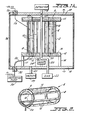
- Figs. 1A and lB show a side cross-sectional view, and a side perspective view, respectively, of the X-ray source constructed in accordance with the invention.
- Fig. 2 is a perspective view of the grid utilized in the present invention.
- Fig. 3 is a timing diagram showing the relative potentials of the cathode, grid, and anode.
- Fig. 4 is a depiction of one embodiment of the present invention in which multiple units are connected in series and grid timing circuitry is used to control the propagation of the X-ray beam.
- Fig. 5 is a view of another embodiment of the present invention in which multiple stages are connected together and which features a unitary grid which controls the propagation of the X-ray beam.
- Fig. 6 shows an embodiment of the present invention in which the X-ray beam repeatedly passes through two stages for amplification.
- Figs. 7A and 7B show a side view and an end view, respectively, of another embodiment of the present invention in which the anode consists of a solid wire, the material of which serves as the atom source for the working medium.
- Figs. 8A and 8B show another embodiment of the invention which uses a laser beam traveling down the inner surface of the cathode in lieu of the grid.
- Fig. 9 shows an embodiment of the present invention in the shape of truncated cones.
- Figs. 10A, 10B and 10C show the output pattern resulting from various shapes of the present invention.
- Referring first to Figs. 1A and 1B, there is shown therein the structure of a single unit of the present invention. The basic structure consists of a cylindrical electrode forming the
cathode 2 having a hollowcentral anode tube 4 disposed on its axis, with acylindrical grid 6 surrounding the anode tube and interposed between the anode and the cathode. Thecathode cylinder 2 has a wall thickness of approximately one centimeter and is formed of a carbon material with a carbon felt lining on its interior surface. Theanode 4 consists of a hollow rod one-half inch in diameter having a wall thickness of a few mils, and is preferably formed of a material such as rhenium or molybdenum.Grid 6 may be formed of any common conductive metal but is preferably comprised of electronic grade nickel or nickel chrome alloy. As shown in further detail in Fig. 2,grid 6 consists ofend rings 8 and a plurality ofslats 10 joining theend rings 8. The slats or fins of the grid are approximately 120 in number, but the number is variable depending on the particular grid configuration desired. - In the preferred embodiment, the diameter of
cathode 2 can range from six inches to two feet. The critical dimension is the ratio of the diameter of cathode to the diameter of anode, this ratio being greater than 10:1. The greater this ratio, the greater will be density of electrons on the anode. It is possible to use other anode/cathode ratios according to geometrical requirements, but the drive requirements will change accordingly. - The
grid 6 is positioned quite close to thecathode 2. Typically, thecathode 2 would be positioned approximately 7.25 inches from theanode 4, with thegrid 6 positioned almost adjacent tocathode 2. - The length of the assembly is typically, but not limited to, one and a half to two feet. As will be discussed in further detail below, however, the preferred length is dependent upon the length of time that the metastable state lasts in the working medium.
- Preferably,
anode 4 is slightly longer thancathode 2 to enable external support of the anode within the cathode. A pair of ceramicsupport end plates cylindrical grooves 14, 15 for receiving the ends ofgrid 6 andcathode 2.Ceramic support insulator 12 is supported bysupport tubes 16, 17 which are mounted onbase plate 18.Base plate 18 and top plate 19 are kept at ground potential. - A stainless or
copper tube 20 is connected toanode 4 for supplying gas to the anode fromgas source 22. The working medium can be any of a variety of gases such as neon, aluminum, sodium, selenium or yttrium. Argon, krypton and xenon may also be used and are particularly desirable since they are gases at room temperature and allow for simpler construction of the device since they need not be vaporized. It is also possible to use liquid mercury as the working medium. The liquid mercury could be preheated by an electrical current to vaporize the mercury in order to produce ionizable atoms. Other liquids or solids can be used provided they are appropriately transparent to the soft X-rays which are produced. - Unless a room temperature gas is used, it is necessary to provide a furnace to form vaporized gas and to force the vaporized gas along the axis of the
anode 4. The furnace may be of any well-known variety, and may operate at a temperature, for example, of 2,500°C. The pressure of the gas in the anode should be as high as possible consistent with the anode wall thickness and the ability of the wall to resist the pressure. - The
anode 4 is electrically coupled to thebase plate 18 bywire 24 and is thereby kept at ground potential.Cathode 2 is electrically coupled to a -150 KV source bywire 26 passing throughinsulator 28. The grid is coupled at one end to a switchingtube 34 bywire connection 30 passing throughinsulator 32. As shown-in further detail in Fig. 2,conductor 30 actually consists of a plurality of wires which lead throughend ring 8 to the ends of theindividual slats 10 ofgrid 6. As shown in Fig 1B, arecess 35 inceramic support insulator 12 is provided for the wires. The individualwires comprising conductor 30 are designed to be the same length to within 1/1000 of an inch, such that the change in voltage from switchingtube 34 reaches each of the slats at approximately the same instant of time. Switching tube 40 is preferably an Eimac Y847 switching tube which can provide a pulse of -150 KV in a length in time of one nanosecond to thegrid 6. - The entire assembly is surrounded by a
glass envelope 36 and a vacuum of 10-6 Torr is maintained inside the glass envelope.Apertures 37 are provided in ceramic support insulators'12, 13 andbase plates 18 to provide connection for the vacuum pump. - Referring now to Fig. 3, in the operation of the device, the cathode is raised to a potential of -150 KV. At this point in time, the flow of electrons to the
anode 4 is blocked by the presence of thegrid 6 at ground potential. However, after a space charge is created atgrid 6, a very sharp pulse of -150 KV potential of one nanosecond duration is applied to one end of the grid throughwire connection 30. The pulse creates a relativistic wave of potential which propagates along the axial length of the grid, releasing electrons from the grid toward the anode as it travels. All of the electrons which are released from the-grid reach theanode 4 within about one nanosecond. The impingement of the electrons on thetubular anode 4 will produce X-rays from the interior surface of the tube, this X-ray flux being the equivalent of the pumping energy of a conventional laser. This X-ray flux, together with the impinging electrons, interacts with the gas ions of the working medium to produce a very high strength pulse of X-rays which sweeps down the length of the anode tube in synchronization with the release of the electrons induced by the propagating grid potential. An electron energy of approximately 200 KeV is easily obtained. The grid geometry should be appropriately designed so that the propagation along the length of the grid will occur at the velocity of light. - The X-rays produced are either ultraviolet or soft X-rays in the wavelength of 50 Angstroms to 200 Angstroms, depending on the working medium used. For example, if selenium gas is used as the working medium, a radiation of approximately 180 Angstroms will result. Other working mediums can produce higher energy X-rays. All X-rays produced by this version of the invention occur in a single pass. That is, there is no traditional multiple reflection as in a true laser, but there is simply amplified stimulated radiation created by the passage of a single wavefront along the axis of the tube (i.e. the tube acts as a superradiant source). The length of the tube assembly should be adjusted to be equal to the length of time that the metastable state exists in the atoms selected from the working.medium. Thus, if selenium is used, which radiates at 180 Angstroms, the lifetime of the metastable state results in a length of tube of approximately one foot, or one nanosecond of time for the existence of the metastable state. The anode wall is made thin so that the electrons that enter into the laser space enhance production of X-rays in that space.
- Since the radiation produced within the
anode tube 4 flows in both directions alongtube 4, it is necessary to provide a suitable X-ray dump 38 at the gas source end of the tube to prevent damage to the gas source orfurnace 22. X-ray dump 38 can, for example, consist of cubic boron nitrates backed by lead and capable of withstanding several thousand degrees Centigrade. - In the embodiment shown in Fig. 1, a detector 40 is present at the open end of
tube anode 4 to measure the amount of X-ray radiation generated. However, in further embodiments of the invention, shown in Figs. 4 and 5, the vapor in theanode 4 can flow to a second stage device having an identical construction to the first which, however, is fired at the instant the output X-ray radiation of the first unit reaches the second unit. This results in the radiation of the second unit being pumped still higher. - In the embodiment shown in Fig. 4, a number of stages are ganged together with their respective grids controlled to fire when the preceding wave arrives.
Grid timing circuitry 42 is provided for this purpose. - In the embodiment shown in Fig. 5, a continuous grid is used for a plurality of stages. The propagation of potential along the grid causes the release of electrons from the continuous grid to the
continuous anode 4 in the manner of a relativistic wave propagating from stage to stage along the length of the axis of the respective cathodes. This arrangement eliminates the requirement for thegrid timing circuitry 42 required in the multi-stage embodiment of Fig. 4. - In the embodiment of the present invention shown in Fig. 6, the X-ray beam repeatedly passes through the same two units by grazing incidence reflection from plane mirrors 41.
Mirror 43 is a beam splitter, so as the intensity of the X-ray beam builds up, anoutput 45 is generated therethrough. The grids of the two (or more) stages are fired alternately to increase the gain (and thus the X-ray beam intensity). - Referring now to Figs. 7A and 7B, a further embodiment of the invention is shown in which the
anode tube 4 containing a vaporized element is replaced by asolid wire 44 of material which is to be vaporized. The material of the wire serves as the atom source of the working medium. The wire is vaporized by the release of electrons fromcathode 2 and must be replaced after each shot. - In the embodiment shown in Figs. 8A and 8B, the grid is eliminated from the system and a fixed voltage is applied to the
cathode 2. Thecathode 2 has a photoemitter material on its internal surface such as nickel lined with cesium iodide or any other material with a low work function. Laser light from an excimer laser (minimum 200 watts) with an output wavelength of 100-300 nanometers is formed by an optical system into a cylindrical tube of light and is arranged to shine on the photoemitter surface ofcathode 2 to induce electron emission. In the example shown in Fig. 8B, the laser light is intercepted by aconical reflector 46 which reflects the cylinder of light out to aparabolic reflector 48, which forms a hollow cylinder of laser light which propagates down the interior of the cathode cylinder. The propagation of the laser light along the photoemitter surface acts like the propagating potential in the previously described embodiments to thereby induce a moving wavefront of X-rays along theanode 4. - Although the present invention has been described with respect to a number of embodiments above, obviously various other modifications are possible. For example, when X-ray mirrors become available that reflect at normal incidence, it will be possible to form a true X-ray laser with traditional multiple internal reflection. Also, as previously mentioned, the cylindrical shape shown in the preferred embodiments is not necessary and various other geometries could operate equally satisfactory.
- Fig. 9 shows an example of the present invention in the shape of a truncated cone. Such a configuration produces a diverging output of laser light.
- Figs. 10A, 10B and 10C show the respective outputs generated from the present invention in various shapes. As previously discussed in connection with Fig. 9, a cone shape produces the diverging output, shown in Fig. 10A. A hyperbolic shape produces a gaussian output as shown in Fig. 10B. A parabolic shape results in a square wave output as shown in Fig. 10C.
- Thus, although the present invention has been described in connection with a plurality of preferred embodiments thereof, many other variations and modifications will now become apparent to those skilled in the art. It is preferred, therefore, that the present invention be limited not by the specific disclosure herein, but only by the appended claims.
Claims (22)
Applications Claiming Priority (2)
| Application Number | Priority Date | Filing Date | Title |
|---|---|---|---|
| US06/860,414 US4723263A (en) | 1985-05-20 | 1986-05-07 | X-ray source |
| US860414 | 1986-05-07 |
Publications (2)
| Publication Number | Publication Date |
|---|---|
| EP0244769A2 true EP0244769A2 (en) | 1987-11-11 |
| EP0244769A3 EP0244769A3 (en) | 1990-02-28 |
Family
ID=25333185
Family Applications (1)
| Application Number | Title | Priority Date | Filing Date |
|---|---|---|---|
| EP87106299A Withdrawn EP0244769A3 (en) | 1986-05-07 | 1987-04-30 | X-ray source |
Country Status (5)
| Country | Link |
|---|---|
| US (1) | US4723263A (en) |
| EP (1) | EP0244769A3 (en) |
| JP (1) | JPS6324532A (en) |
| CA (1) | CA1278017C (en) |
| IL (1) | IL82429A0 (en) |
Cited By (2)
| Publication number | Priority date | Publication date | Assignee | Title |
|---|---|---|---|---|
| EP2501437A1 (en) * | 2008-05-16 | 2012-09-26 | Advanced Fusion Systems LLC | Flash x-ray irradiator |
| EP3208808A1 (en) * | 2006-05-30 | 2017-08-23 | Advanced Fusion Systems LLC | Electron-coupled transformer |
Families Citing this family (11)
| Publication number | Priority date | Publication date | Assignee | Title |
|---|---|---|---|---|
| US4950962A (en) * | 1985-05-20 | 1990-08-21 | Quantum Diagnostics, Ltd. | High voltage switch tube |
| US5930331A (en) * | 1989-03-22 | 1999-07-27 | Rentzepis; Peter M. | Compact high-intensity pulsed x-ray source, particularly for lithography |
| US5082900A (en) * | 1989-03-29 | 1992-01-21 | Chisso Corporation | Opacified molded product |
| JP4584470B2 (en) * | 2001-02-01 | 2010-11-24 | 浜松ホトニクス株式会社 | X-ray generator |
| WO2007074029A1 (en) * | 2005-12-27 | 2007-07-05 | Siemens Aktiengesellschaft | Focus detector arrangement for generating phase-contrast x-ray images and method for this |
| DE502006007410D1 (en) * | 2005-12-27 | 2010-08-26 | Paul Scherrer Inst Psi | Focus-detector arrangement for generating phase-contrast X-ray images and method for this purpose |
| US7742571B1 (en) * | 2006-04-17 | 2010-06-22 | Roman Krzystyniak | Grid control system for eliminating soft radiation emissions from an X-ray tube |
| JP5580825B2 (en) | 2008-08-28 | 2014-08-27 | アドバンスド フュージョン システムズ リミテッド ライアビリティー カンパニー | Method for injecting a predetermined energy and quantity of electrons into a plasma derived from an inertial confinement fusion fuel |
| US8248740B2 (en) * | 2008-09-19 | 2012-08-21 | Advanced Fusion Systems, Llc | High speed current shunt |
| DE102018114295A1 (en) * | 2018-06-14 | 2019-12-19 | Paul Höss Kg | Device for generating a filamentary auxiliary discharge for a device for generating X-rays and particle radiation and for a fusion reactor with the device for generating X-rays and particle radiation and method for generating X-rays and particle radiation |
| CN111524772B (en) * | 2020-05-28 | 2022-07-08 | 西北核技术研究院 | Cascade bremsstrahlung reflection triode |
Citations (4)
| Publication number | Priority date | Publication date | Assignee | Title |
|---|---|---|---|---|
| US3970884A (en) * | 1973-07-09 | 1976-07-20 | Golden John P | Portable X-ray device |
| GB2025729A (en) * | 1978-07-10 | 1980-01-23 | Butler Newton Inc | Radiation imaging apparatus |
| US4229708A (en) * | 1977-04-08 | 1980-10-21 | Avco Everett Research Laboratory, Inc. | X-ray laser |
| EP0037917A1 (en) * | 1980-04-11 | 1981-10-21 | International Business Machines Corporation | Flash X-ray source |
Family Cites Families (2)
| Publication number | Priority date | Publication date | Assignee | Title |
|---|---|---|---|---|
| US3567940A (en) * | 1969-02-24 | 1971-03-02 | Gen Electric | Cineradiographic x-ray tube grid pulsing circuit employing series connected high voltage switching transistors |
| US4042827A (en) * | 1973-10-03 | 1977-08-16 | Research Corporation | Stimulated emission X-ray generator |
-
1986
- 1986-05-07 US US06/860,414 patent/US4723263A/en not_active Expired - Fee Related
-
1987
- 1987-04-30 EP EP87106299A patent/EP0244769A3/en not_active Withdrawn
- 1987-05-05 IL IL82429A patent/IL82429A0/en unknown
- 1987-05-06 CA CA000536525A patent/CA1278017C/en not_active Expired - Fee Related
- 1987-05-07 JP JP62113403A patent/JPS6324532A/en active Pending
Patent Citations (4)
| Publication number | Priority date | Publication date | Assignee | Title |
|---|---|---|---|---|
| US3970884A (en) * | 1973-07-09 | 1976-07-20 | Golden John P | Portable X-ray device |
| US4229708A (en) * | 1977-04-08 | 1980-10-21 | Avco Everett Research Laboratory, Inc. | X-ray laser |
| GB2025729A (en) * | 1978-07-10 | 1980-01-23 | Butler Newton Inc | Radiation imaging apparatus |
| EP0037917A1 (en) * | 1980-04-11 | 1981-10-21 | International Business Machines Corporation | Flash X-ray source |
Non-Patent Citations (1)
| Title |
|---|
| PATENT ABSTRACTS OF JAPAN, unexamined applications, E field, vol. 7, no. 88, April 12, 1983 THE PATENT OFFICE JAPANESE GOVERNMENT page 25 E 170 * |
Cited By (4)
| Publication number | Priority date | Publication date | Assignee | Title |
|---|---|---|---|---|
| EP3208808A1 (en) * | 2006-05-30 | 2017-08-23 | Advanced Fusion Systems LLC | Electron-coupled transformer |
| US10181376B2 (en) | 2006-05-30 | 2019-01-15 | Advanced Fusion Systems Llc | Electron-coupled transformer |
| EP2501437A1 (en) * | 2008-05-16 | 2012-09-26 | Advanced Fusion Systems LLC | Flash x-ray irradiator |
| EP2501437A4 (en) * | 2008-05-16 | 2013-08-07 | Advanced Fusion Systems Llc | Flash x-ray irradiator |
Also Published As
| Publication number | Publication date |
|---|---|
| JPS6324532A (en) | 1988-02-01 |
| CA1278017C (en) | 1990-12-18 |
| EP0244769A3 (en) | 1990-02-28 |
| IL82429A0 (en) | 1987-11-30 |
| US4723263A (en) | 1988-02-02 |
Similar Documents
| Publication | Publication Date | Title |
|---|---|---|
| US6346770B1 (en) | Discharge device having cathode with micro hollow array | |
| US4504964A (en) | Laser beam plasma pinch X-ray system | |
| US4723263A (en) | X-ray source | |
| US6172324B1 (en) | Plasma focus radiation source | |
| JP2750349B2 (en) | In particular, a plasma X-ray tube for gas laser X-ray-preionization, a method of generating X-ray radiation by this X-ray tube and its use | |
| US6134300A (en) | Miniature x-ray source | |
| US4670894A (en) | X-ray source employing cold cathode gas discharge tube with collimated beam | |
| US3751701A (en) | Convergent flow hollow beam x-ray gun with high average power | |
| US3956712A (en) | Area electron gun | |
| JP2750348B2 (en) | X-ray of gas laser, especially for plasma X-ray tube for pre-ionization and application as electron gun | |
| US6185276B1 (en) | Collimated beam x-ray tube | |
| US5057740A (en) | Photoemissive trigger for backlighted thyratron switches | |
| JPS6122545A (en) | X-ray tube | |
| US3881132A (en) | Compact, high intensity arc lamp with internal magnetic field producing means | |
| US3821580A (en) | Flash x ray tube | |
| US3497827A (en) | Gas laser utilizing the negative glow in a cold cathode glow discharge tube | |
| US3531734A (en) | Ion laser having metal cylinders to confine the discharge | |
| US4680770A (en) | Dual beam gas ion laser | |
| US4825446A (en) | Laser apparatus having cathode bore directing electron beam onto anode | |
| WO1987005159A1 (en) | Cold electrode metal vapour laser | |
| EP0101043A2 (en) | Plasma cathode electron beam generating system | |
| US2540537A (en) | Vacuum tube current amplifier | |
| GB2194673A (en) | Apparatus for forming an electron beam sheet | |
| SU1080668A1 (en) | Electron gun intended,mainly,for gas lasers | |
| Whaley et al. | PPM focused TWT using a field emitter array cold cathode |
Legal Events
| Date | Code | Title | Description |
|---|---|---|---|
| PUAI | Public reference made under article 153(3) epc to a published international application that has entered the european phase |
Free format text: ORIGINAL CODE: 0009012 |
|
| AK | Designated contracting states |
Kind code of ref document: A2 Designated state(s): BE CH DE FR GB IT LI NL SE |
|
| PUAL | Search report despatched |
Free format text: ORIGINAL CODE: 0009013 |
|
| AK | Designated contracting states |
Kind code of ref document: A3 Designated state(s): BE CH DE FR GB IT LI NL SE |
|
| STAA | Information on the status of an ep patent application or granted ep patent |
Free format text: STATUS: THE APPLICATION IS DEEMED TO BE WITHDRAWN |
|
| 18D | Application deemed to be withdrawn |
Effective date: 19900829 |
|
| RIN1 | Information on inventor provided before grant (corrected) |
Inventor name: HEESE,RICHARD Inventor name: BIRNBACH, CURTIS Inventor name: TANNER, JAY |