EP0243586A2 - Electromechanical locking device with an individual key - Google Patents
Electromechanical locking device with an individual key Download PDFInfo
- Publication number
- EP0243586A2 EP0243586A2 EP87101313A EP87101313A EP0243586A2 EP 0243586 A2 EP0243586 A2 EP 0243586A2 EP 87101313 A EP87101313 A EP 87101313A EP 87101313 A EP87101313 A EP 87101313A EP 0243586 A2 EP0243586 A2 EP 0243586A2
- Authority
- EP
- European Patent Office
- Prior art keywords
- key
- lock
- memory
- code
- locking
- Prior art date
- Legal status (The legal status is an assumption and is not a legal conclusion. Google has not performed a legal analysis and makes no representation as to the accuracy of the status listed.)
- Withdrawn
Links
Images

Classifications
-
- E—FIXED CONSTRUCTIONS
- E05—LOCKS; KEYS; WINDOW OR DOOR FITTINGS; SAFES
- E05B—LOCKS; ACCESSORIES THEREFOR; HANDCUFFS
- E05B47/00—Operating or controlling locks or other fastening devices by electric or magnetic means
- E05B47/06—Controlling mechanically-operated bolts by electro-magnetically-operated detents
- E05B47/0611—Cylinder locks with electromagnetic control
- E05B47/0638—Cylinder locks with electromagnetic control by disconnecting the rotor
- E05B47/0642—Cylinder locks with electromagnetic control by disconnecting the rotor axially, i.e. with an axially disengaging coupling element
-
- G—PHYSICS
- G07—CHECKING-DEVICES
- G07C—TIME OR ATTENDANCE REGISTERS; REGISTERING OR INDICATING THE WORKING OF MACHINES; GENERATING RANDOM NUMBERS; VOTING OR LOTTERY APPARATUS; ARRANGEMENTS, SYSTEMS OR APPARATUS FOR CHECKING NOT PROVIDED FOR ELSEWHERE
- G07C9/00—Individual registration on entry or exit
- G07C9/00174—Electronically operated locks; Circuits therefor; Nonmechanical keys therefor, e.g. passive or active electrical keys or other data carriers without mechanical keys
- G07C9/00182—Electronically operated locks; Circuits therefor; Nonmechanical keys therefor, e.g. passive or active electrical keys or other data carriers without mechanical keys operated with unidirectional data transmission between data carrier and locks
-
- E—FIXED CONSTRUCTIONS
- E05—LOCKS; KEYS; WINDOW OR DOOR FITTINGS; SAFES
- E05B—LOCKS; ACCESSORIES THEREFOR; HANDCUFFS
- E05B47/00—Operating or controlling locks or other fastening devices by electric or magnetic means
- E05B2047/0092—Operating or controlling locks or other fastening devices by electric or magnetic means including means for preventing manipulation by an external magnetic field, e.g. preventing opening by using a strong magnet
-
- G—PHYSICS
- G07—CHECKING-DEVICES
- G07C—TIME OR ATTENDANCE REGISTERS; REGISTERING OR INDICATING THE WORKING OF MACHINES; GENERATING RANDOM NUMBERS; VOTING OR LOTTERY APPARATUS; ARRANGEMENTS, SYSTEMS OR APPARATUS FOR CHECKING NOT PROVIDED FOR ELSEWHERE
- G07C9/00—Individual registration on entry or exit
- G07C9/00174—Electronically operated locks; Circuits therefor; Nonmechanical keys therefor, e.g. passive or active electrical keys or other data carriers without mechanical keys
- G07C2009/00753—Electronically operated locks; Circuits therefor; Nonmechanical keys therefor, e.g. passive or active electrical keys or other data carriers without mechanical keys operated by active electrical keys
- G07C2009/00761—Electronically operated locks; Circuits therefor; Nonmechanical keys therefor, e.g. passive or active electrical keys or other data carriers without mechanical keys operated by active electrical keys with data transmission performed by connected means, e.g. mechanical contacts, plugs, connectors
Definitions
- the invention relates to a cylinder lock and / or locking system with at least one lock containing a changeable coding and decoding device and at least one key which can be made suitable or unsuitable as a master or secondary key.
- a locking system in which programmable locks connected to a central unit and programmable keys are available, in which a master key can make secondary keys suitable or not suitable.
- This system requires external electronics and the connection of locks by means of a central unit, as well as an external power supply and an additional magnetic field to carry out the actual locking process.
- a key-specific code stored in the lock, but also a code relating only to this lock is stored in the key, so that for each lock for which the key receives a locking authorization , memory locations are occupied in the key.
- All previously known locks consist of 3 components and an external energy supply. These 3 components are the electronic control and monitoring unit, the electromechanical unit and the locking unit.
- the electronic control and monitoring unit is used for storing, coding and decoding Key codes, as well as the recognition of locking authorization.
- the electromechanical unit either actuates a lock or a bolt, that is to say the locking unit, or clears the way for actuating the locking unit.
- the previously known constructive solutions of electronic locks are so space and energy consuming that, for example, in addition to the lock and lock cylinder, an electronic component, an electromechanical component and an external power supply have to be accommodated. Such a construction takes up a lot of space and is costly
- These solutions have the traditional relationship between a key and a lock, so it is not possible to lock a large number of locks with as few keys as possible without losing security.
- the invention seeks to remedy this.
- the invention as characterized in the claims, solves the task of a space-saving electronic lock to replace conventional lock cylinders without structural changes and elimination of the relationship between key and lock required by mechanical coding without security loss in that an initially neutral lock the codes receives all those keys that are authorized to lock and, because it is a mechanical unit key, can also lock.
- the essence of the solution is that the electronic control and monitoring unit can be completely housed in the lock cylinder, for example a standard lock according to DIN 18 252.
- a part of the electronics that is not required for the pure locking authorization check, such as memory programming, querying the entire memory allocation, checking whether a key is authorized to give further keys locking authorization len, outsourced to a separate mobile service device.
- the lock part contains a memory in the lock cylinder, in which key codes can be saved and deleted using looo.
- Each key receives an individual code, a processor and a power supply, with each key mechanically fitting into each lock.
- Each lock can now be entered by means of a service device, which key is to be given a locking authorization and, if necessary, which key is to be withdrawn from a locking authorization once it has been stored.
- each key has an individual code and duplicates, as were previously the case with locks that should be locked by different people, would endanger security. Instead of issuing duplicates for a lock that should be able to be locked by different people, all codes of the keys with locking authorization are stored in the lock. Then different people who only have one key can do so close identical (identical) locks as well as locks that others cannot close.
- the simple design enables manufacturing costs that do not exceed those of conventional locking cylinders, so that use is not limited to areas with increased security requirements.
- the key Fig. 1.2 consists of a standardized shaft part and a freely and individually designable handle part.
- the shaft part is designed in such a way that each key mechanically fits into each key channel of each cylinder core.
- the key shaft transmits energy and data in the cylinder core at defined points and, due to its nature, is able to transmit the required mechanical locking forces to the lock bit.
- Energy is preferably transmitted via galvanic connections (contacts).
- the data can either be transmitted via galvanic connections (contacts) or contactlessly via optical elements (e.g. via LED or LASER diodes).
- the handle part Fig. 1.2 and Fig. 5 contains the primary and secondary power supply (eg active and replacement battery terie), the clock generator, the processor, the program memory, the number memory, the programming control, the transmitter and receiver, and the error display.
- the primary and secondary power supply eg active and replacement battery terie
- the number memory contains a single, unique code once assigned.
- the cylinder core is preferably freely rotatable in the cylinder housing. In this case, it contains a standard opening on one side, into which the shaft of the key fits. This side is protected by a hard metal disc Fig. 1.5. Behind it is an electrically insulating part Fig. 1.6, which contains the necessary contacts and decoding and activation unit. This part is secured by the guide Fig. 2 against rotation to the cylinder core.
- FIG. 1 Behind part 6 of Fig. 1 is the freely movable coupling part Fig. 1.4, which is also secured by the guide Fig. 2 against rotation to the cylinder core, but can be moved axially.
- This coupling part is provided with a groove on which the coil Fig. 1.7 is applied.
- the coupling part can snap into the grooves Fig. 1.9 (on part 3) of the lock bit Fig. 1.3 and thus enable the power transmission of the key Fig. 1.2 to the lock bit Fig. 1.3.
- This arrangement prevents an unauthorized coupling of the lock cylinder to the lock bit being made possible by applying an external strong magnetic field.
- the spring Fig. 1.1o ensures safe decoupling of the clasp from the lock bit when the coil is not activated. Due to the symmetrical structure of the locking system, use from opposite sides is possible.
- the dimensions selected in the description above are based on the standards of the most frequently used locking cylinder according to DIN 18 252.
- the explained mechanics, electronics and electromechanics can also be accommodated in smaller and larger cylinder cores.
- the reduction in the external dimensions of the locking cylinder is only limited by the dimension of the key shaft.
- the control unit itself consists of a central processor unit (CPU), a clock generator, a power-up reset and the data transmission and reception unit.
- the power-up reset ensures a defined initial state of the complete unit after the energy has been switched on.
- the clock generator generates the clocks required for the CPU and the transmitting and receiving unit. Furthermore, a synchronization clock is generated for the evaluation unit in the cylinder core and transferred via the transmission element Fig. 5.4.
- the program in the CPU contains all communication processes to the control and evaluation unit in the cylinder core, the variable coding algorithm, the individual code number and a special programming process.
- the CPU manages all program parts and evaluates the responses coming from the control and evaluation unit of the cylinder core.
- the transmitter and receiver unit converts the computer signals accordingly to the transmission parameters in send signals, or receive signals in computer signals.
- a special feature is the internal programming control for the subsequent programming of the key number. External access to address and data lines is not necessary, as is the case with conventional programming of this memory, but is made possible internally by special programming hardware and the associated programming sequence.
- a protocol is sent to the CPU via the transmission element 5 and the associated receiver, on the basis of which the programming sequence is called and which in turn puts the programming hardware into operation.
- the key code is transferred to the CPU by a handshake process, which then requests the external programming pulse on transmission element 7, as a result of which the key code is permanently programmed into the memory.
- the transmission element Fig. 5.7 is part of the control unit and can only be accessed by the authorized programming unit before installation in the key. After successful and verified programming, the transmission element 7 is electrically disconnected from the control unit and is therefore inoperative forever.
- the electrically insulating part Fig. 1.6 contains all transmission elements, the control and evaluation unit, as well as the bridge of the transmission elements Fig. 1.2 and Fig. 1.3 for energizing the key.
- the control and evaluation unit is normally supplied with energy from the key.
- the control and evaluation unit consists of a central processor unit (CPU), clock synchronization, a power-up reset, the data transmission and reception unit, several memory groups, the memory programming device, a lock activation, a lock coupling measurement system, an alarm unit and the device_an additional energy supply.
- the power-up reset ensures a defined initial state of the complete unit after the energy has been switched on.
- the clock synchronizer receives the synchronization clock from the key via the transmission element Fig. 5.4 and derives therefrom all necessary clock signals for the CPU and the transmitting and receiving unit in a synchronized manner.
- the program in the CPU includes all communication flows to and from the key, the variable coding - algorithm, the particular programming sequence for storing fixed value numbers, the management of the number memory, the measurement and activation of the coupling part, and an alarm evaluation and reporting and a ring memory.
- the transmitting and receiving unit converts the computer signals according to the transmission parameters into transmission signals, or reception signals into computer signals.
- the memory programming device works analogously to that in the key. The only difference is that there is much more memory space for codes and the programming routine manages a correspondingly larger memory.
- the lock activation switches when authorization is recognized the key to the energy on the electromechanical part and thus couples the freely rotatable cylinder core with the lock bit, which enables the power transmission from the key to the lock.
- the energy supply is switched off and the lock can be actuated until the key is removed from the cylinder core by locking by means of the bending spring FIG. 4.
- locking pin Fig. 4.11 blocks the coupling in the second cylinder core.
- the bending spring is thus against a groove in part Fig. 4.4 by the pin Fig. 4.5. pressed that after coupling of part Fig. 4.4 it slides over the edge of the groove and remains on the back of part Fig. 4.4, so that it can no longer move back to its starting position and thus via the locking pin, the coupling of the opposite one Fig. 4.4 is prevented.
- the key is inserted, it cannot be locked from the opposite side.
- the service device contains at least 2 sockets Fig. 7.1. and 7.2 for socket wrenches, a socket wrench adapter Fig. 7.3, a display field Fig. 7.4 and an input field Fig. 7.5, as well as the required transmission, reception and processing electronics and their energy supply.
- the service device is used to store key codes in the lock's memory. To do this, the key adapter is pushed into the key channel of the locking cylinder. The device then checks whether any code of a key is already stored in the lock's memory. If no key code has yet been stored, the code of the key which is inserted in the socket wrench insertion 1 is stored. This key (or the keys, if a key is also in socket wrench insertion 2 e) is then authorized in the future to grant or withdraw other keys.
- any further programming of key codes in the lock's memories takes place in such a way that the key, the code of which is to be stored in the lock memory, is inserted into the socket insertion 2 at the service device; the servo device then checks whether the key is inserted in socket wrench insertion 1, the code of which is stored in the lock at the 1st position and, if applicable, the new key code is stored; where a number appears in the display field Fig. 7.4, indicating the number at which the new key is stored.
- To delete a locking authorization of a key it is then sufficient to insert the key with programming authorization for this lock into the socket entry No. 1 and then to type in the location number of the key whose locking authorization is to be deleted. At no point does the code itself come to light.
Abstract
Description
Die Erfindung bezieht sich auf ein Zylinderschloss und/ oder Schliessanlage mit mindestens einem eine veränderbare Codier- und Dekodiereinrichtung enthaltenden Schloss und mindestens einem Schlüssel, der als Haupt-oder Nebenschlüssel passend oder unpassend gemacht werden kann. I The invention relates to a cylinder lock and / or locking system with at least one lock containing a changeable coding and decoding device and at least one key which can be made suitable or unsuitable as a master or secondary key. I.
Aus der Schrift DE - PS 30 31 405 ist eine Schließanlage bekannt, bei welcher programmier_bare Schlösser verbunden mit einer Zentraleinheit und programmierbare Schlüssel vorhanden sind, in welcher ein Hauptschlüssel Nebenschlüssel passend oder nichtpassend machen kann. Dieses System benötigt schloßexterne Elektronik und die Verknüpfung von Schlössern mittels Zentraleinheit, sowie eine externe Energieversorgung und ein zusätzliches Magnetfeld zur Durchführung des eigentlichen Schließvorgangs. Desweiteren wird für jeden Schlüssel, der berechtigt sein soll, ein bestimmtes Schloß zu schließen, nicht nur im Schloß ein schlüsselspezifischer Code gespeichert sondern auch im Schlüssel ein nur dieses Schloß betreffender Code gespeichert, so daß für jedes Schloß, für welches der Schlüssel eine Schließberechtigung erhält, im Schlüssel Speicherplätze belegt werden.From the document DE-PS 30 31 405 a locking system is known, in which programmable locks connected to a central unit and programmable keys are available, in which a master key can make secondary keys suitable or not suitable. This system requires external electronics and the connection of locks by means of a central unit, as well as an external power supply and an additional magnetic field to carry out the actual locking process. Furthermore, for each key that is supposed to be authorized to lock a particular lock, not only is a key-specific code stored in the lock, but also a code relating only to this lock is stored in the key, so that for each lock for which the key receives a locking authorization , memory locations are occupied in the key.
Alle bisher bekannten S chlösser bestehen aus 3 Bauelementen und einer externen Energieversorgung. Diese 3 Bauelemente sind die elektronische Steuer- und Kontrolleinheit, die elektromechanische Einheit und die Sperreinheit. Die elektronische Steuer- und Kontrolleinheit dient zur Speicherung, Codierung und Decodierung von Schlüsselcodes, sowie der Erkennung von Schließberechtigung. Die elektromechanische Einheit betätigt entweder ein Schloß oder einen Riegel, also die Sperreinheit, oder gibt den Weg zum Betätigen der Sperreinheit frei. Die bisher bekannten konstruktorischen Lösungen von elektronischen Schlössern sind so raum-"und energieaufwendig, daß beispielsweise zusätzlich zum Schloß und Schließzylinder ein elektronisches Bauteil, ein elektromechanisches Bauteil und eine externe Energieversorgung unterzubringen sind. Eine solche Konstruktion hat hohen Raumbedarf und ist kostenaufwendig. Desweiteren bleibt bei diesen Lösungen die herkömmliche Beziehung zwischen Schlüssel und Schloß bestehen. Es ist also nicht möglich, ohne Sicherheitsverlust mit möglichst wenigen Schlüsseln viele Schlösser schließen zu können.All previously known locks consist of 3 components and an external energy supply. These 3 components are the electronic control and monitoring unit, the electromechanical unit and the locking unit. The electronic control and monitoring unit is used for storing, coding and decoding Key codes, as well as the recognition of locking authorization. The electromechanical unit either actuates a lock or a bolt, that is to say the locking unit, or clears the way for actuating the locking unit. The previously known constructive solutions of electronic locks are so space and energy consuming that, for example, in addition to the lock and lock cylinder, an electronic component, an electromechanical component and an external power supply have to be accommodated. Such a construction takes up a lot of space and is costly These solutions have the traditional relationship between a key and a lock, so it is not possible to lock a large number of locks with as few keys as possible without losing security.
Hier will die Erfindung Abhilfe schaffen. Die Erfindung, wie sie in den Ansprüchen gekennzeichnet ist, löst die Aufgabe, ein raumsparendes elektronisches Schloß zum Ersatz herkömmlicher Schließzylinder ohne bauliche Veränderung und Beseitigung der durch mechanische Codierung notwendigen Beziehung zwischen Schlüssel und Schloß ohne Sicherheits verlust dadurch, daß ein zunächst neutrales Schloß die Codes all jener Schlüssel eingespeichert erhält, die Schließbere chtigung haben und, da es sich um einen mechanischen Einheitsschlüssel handelt, dann auch schließen können. Das Wesen der Lösung ist, daß die elektronische Steuer- und Kontrolleinheit vollständig im Schließzylinder, beispielsweise eines Normschlosses nach DIN 18 252, untergebracht werden kann. Dazu wird ein Teil der Elektronik, welcher nicht zur reinen Schließberechtigungsprüfung benötigt wird, wie z.B. Speicherprogrammierung, Abfrage der gesamten Speicherbelegung, Prüfung, ob ein Schlüssel berechtigt ist, weiteren Schlüsseln eine Schließberechtigung zu erteilen, in ein gesondertes mo biles Servicegerät ausgelagert. Damit auch zur Energieversorgung keine bauliche Veränderung notwendig ist, wird diese im Schlüssel untergebracht zur Versorgung der Gesamtelektronik des Systems und zum Betreiben der Elektromechanik, deren Energieaufnahme dadurch im 1 m As gehalten werden kann, daß der Zylinder nicht durch Zuhaltestifte blockiert ist, sondern frei dreht und im Falle einer Schließberechtigung ein Teil mit geringerem Gewicht als 1 Gramm magnetisch einkoppelt zur Kraftübertragung von Schlüssel auf Schließbart.The invention seeks to remedy this. The invention, as characterized in the claims, solves the task of a space-saving electronic lock to replace conventional lock cylinders without structural changes and elimination of the relationship between key and lock required by mechanical coding without security loss in that an initially neutral lock the codes receives all those keys that are authorized to lock and, because it is a mechanical unit key, can also lock. The essence of the solution is that the electronic control and monitoring unit can be completely housed in the lock cylinder, for example a standard lock according to DIN 18 252. For this purpose, a part of the electronics that is not required for the pure locking authorization check, such as memory programming, querying the entire memory allocation, checking whether a key is authorized to give further keys locking authorization len, outsourced to a separate mobile service device. So that no structural changes are necessary for the energy supply, it is housed in the key for supplying the entire electronics of the system and for operating the electromechanics, whose energy consumption can be kept in 1 m As by not blocking the cylinder with locking pins, but rotating it freely and in the case of a locking authorization, a part with a weight of less than 1 gram magnetically couples in to transmit power from the key to the lock bit.
Der Schloßteil enthält im Schließzylinder einen Speicher, in welchem über looo Schlüsselcodes gespeichert und wieder gelöscht werden können. Jeder Schlüssel erhält einen individuellen Code, einen Prozessor und eine Energieversorgung, wobei jeder Schlüssel mechanisch in jedes Schloß paßt.The lock part contains a memory in the lock cylinder, in which key codes can be saved and deleted using looo. Each key receives an individual code, a processor and a power supply, with each key mechanically fitting into each lock.
Jedem Schloß kann nun mittels Servicegerät eingegeben werden, welcher Schlüssel eine Schließberechtigung erhalten soll und gegebenenfalls welchem Schlüssel eine einmal durch Speicherung erteilte Schließbere chtigung entzogen werden soll.Each lock can now be entered by means of a service device, which key is to be given a locking authorization and, if necessary, which key is to be withdrawn from a locking authorization once it has been stored.
Wesentlich ist, daß hier jeder Schlüssel einen individuellen Code hat und Doubletten, wie sie bisher bei Schlössern üblich sind, die von verschiedenen Personen geschlossen werden sollen, die Sicherheit gefährden würden. Anstelle der Ausgabe von Doubletten für ein Schloß, das von verschiedenen Personen geschlossen werden können soll, werden in das Schloß alle Codes der Schlüssel mit Schließberechtigung eingespeichert. Dann können verschiedene Personen, die dann nur einen Schlüssel haben, sowohl gleiche (identische)Schlösser schließen, als auch Schlösser schließen, die andere nicht schließen können.It is essential that each key has an individual code and duplicates, as were previously the case with locks that should be locked by different people, would endanger security. Instead of issuing duplicates for a lock that should be able to be locked by different people, all codes of the keys with locking authorization are stored in the lock. Then different people who only have one key can do so close identical (identical) locks as well as locks that others cannot close.
Die durch die Erfindung erreichten Vorteile sind im wesentlichen darin zu sehen, daß sich ein solches Schloß eignet sowohl für alle jene Verwendungen herkömmlicher Schließzylinder als auch für den Einsatz in Zentralschließanlagen und Hauptschlüsselanlagen. Das System ist also aufwärts kompatibel vom einfachen einzelnen Schloß bis zur kompliziertesten Zentralschließ- und Hauptschlüsselanlage, wobei dieses System erstmalig die Möglichkeit beinhaltet, daß ein Schlüsselträger im Idealfall mit nur einem Schlüssel sämtliche Schlösser, für welche er eine Berechtigung hat, ohne Sicherheitsverlust schließen kann, wofür bei herkömmlichen Systemen eine Vielzahl von Schlüsseln (Haustüre, Garage, Auto, Firma, Hotel, Tressor, Aktenschrank u.a.) notwendig sind. Dabei kann jedes Schloß ohne Veränderung Einsatz finden als Zimmer-, Haus- und auch als Haustürschloß in einer Zentralschließanlage. Die Funktion ergibt sich aus dem oder den eingespeicherten Codes. Der Einbau ist ohne bauliche Veränderung möglich, da nur und nur der alte Schließzylinder nebst Schließzylindergehäuse getauscht werden muß. Bei Verlust ist nun nicht mehr aus Sicherheitsgründen ein Austausch der Anlage erforderlich, sondern es genügt das Löschen des entsprechenden Codes mittels Servicegerät. Dabei wird ü-ber die Einga-be der Speicherplatznummer dieser Code gelöscht; diese Nummer ist bei Einspeicherung des Codes am Servicegerät abzulesen gewesen. Der Code selbst wird weder beim Einspeichern noch beim Löschen oder beim Schließen direkt und damit ermittelbar übertragen.The advantages achieved by the invention are essentially to be seen in the fact that such a lock is suitable for all those uses of conventional lock cylinders as well as for use in central locking systems and master key systems. The system is therefore upwards compatible from the simple individual lock to the most complicated central locking and master key system, whereby this system includes for the first time the possibility that a key holder can ideally lock all the locks for which he is authorized without a loss of security with just one key, for which a large number of keys (front door, garage, car, company, hotel, processor, filing cabinet, etc.) are required for conventional systems. Each lock can be used without change as a room, house and also front door lock in a central locking system. The function results from the stored code or codes. Installation is possible without structural changes, since only and only the old lock cylinder and lock cylinder housing need to be replaced. If it is lost, it is no longer necessary to replace the system for security reasons; simply delete the corresponding code using the service device. This code is deleted by entering the memory location number; this number was read on the service device when the code was saved. The code itself is not transmitted directly and thus ascertainable, neither when saving nor when deleting or when closing.
Die einfache Bauweise ermöglicht Herstellungskosten, die jene herkömmlicher Schließzylinder nicht übersteigen, so daß der Einsatz nicht nur auf Gebiete mit erhöhtem Sicherheits-bedarf beschränkt ist.The simple design enables manufacturing costs that do not exceed those of conventional locking cylinders, so that use is not limited to areas with increased security requirements.
Im Folgenden wird die Erfindung anhand von lediglich einen Ausführungsweg darstellenden Zeichnungen näher erläutert.In the following, the invention will be explained in more detail with reference to drawings that show only one embodiment.
Es zeigen
- Figur 1: Zylinderkern mit Schließbart und Schlüssel
- Figur 2: Schnitt des Zylinderkerns an II nach Fig. 1
- Figur 3: Schnitt des Zylinderkerns an III nach Fig, 1
- Figur 4: Arretierungsmechanismus bei Stecken eines Schlüssels
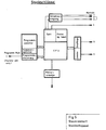
- Figur 5: Blockschaltbild der Steuereinheit Schlüssel
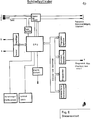
- Figur 6: Blockschaltbild der Steuereinheit Zylinderkern
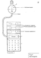
- Figur 7: schematische Darstellung Servicegerät
- Figure 1: cylinder core with lock bit and key
- Figure 2: Section of the cylinder core on II of FIG. 1st
- FIG. 3: section of the cylinder core on III according to FIG. 1
- Figure 4: locking mechanism when inserting a key
- Figure 5: Block diagram of the key control unit
- Figure 6: Block diagram of the control unit cylinder core
- Figure 7: schematic representation of the service device
Der Schlüssel Fig. 1.2 besteht aus einem normierten Schaftteil und einem frei und individuell gestaltbaren Griffteil. Das Schaftteil ist so gestaltet, daß jeder Schlüssel mechanisch in jeden Schlüsselkanal jedes Zylinderkerns paßt.The key Fig. 1.2 consists of a standardized shaft part and a freely and individually designable handle part. The shaft part is designed in such a way that each key mechanically fits into each key channel of each cylinder core.
Der Schlüsselschaft überträgt an definierten Stellen Energie und Daten in den Zylinderkern und ist durch seine Beschaffenheit in der Lage, die erforderlichen mechanischen Schließkräfte auf den Schließbart zu übertragen. Die Energieübertragung erfolgt vorzugsweise über galvanische Verbindungen (Kontakte). Die Daten können entweder über galvanische Ver bindungen (Kontakte) oder berührungslos über optische Elemente (z.B. über LED oder LASER-Dioden) übertragen werden.The key shaft transmits energy and data in the cylinder core at defined points and, due to its nature, is able to transmit the required mechanical locking forces to the lock bit. Energy is preferably transmitted via galvanic connections (contacts). The data can either be transmitted via galvanic connections (contacts) or contactlessly via optical elements (e.g. via LED or LASER diodes).
Der Griffteil Fig. 1.2 und Fig. 5 enthält die primäre und sekundäre Stromversorgung.(z.B. Aktiv- und Ersatzbatterie), den Taktgeber, den Prozessor, den Programmspeicher, den Nummernspeicher, die Programmiersteuerung, den Sender und Empfänger, sowie die Fehleranzeige.The handle part Fig. 1.2 and Fig. 5 contains the primary and secondary power supply (eg active and replacement battery terie), the clock generator, the processor, the program memory, the number memory, the programming control, the transmitter and receiver, and the error display.
Der Nummernspeicher enthält einen einzigen individuellen einmal vergebenen Code.The number memory contains a single, unique code once assigned.
Der Zylinderkern ist im Zylindergehäuse vorzugsweise frei dreh bar. Er enthält in diesem Falle auf der einen Seite eine Normöffnung, in welche der Schaft des Schlüssels paßt. Diese Seite ist durch eine hartmetallische Scheibe Fig. 1.5 geschützt. Dahinter befindet sich ein elektrisch isolierender Teil Fig. 1.6, der die notwendigen Kontakte und Dekodier- und Aktiviereinheit enthält. Dieser Teil ist durch die Führung Fig. 2 gegen Verdrehung zum Zylinderkern gesichert.The cylinder core is preferably freely rotatable in the cylinder housing. In this case, it contains a standard opening on one side, into which the shaft of the key fits. This side is protected by a hard metal disc Fig. 1.5. Behind it is an electrically insulating part Fig. 1.6, which contains the necessary contacts and decoding and activation unit. This part is secured by the guide Fig. 2 against rotation to the cylinder core.
Hinter Teil 6 der Fig. 1 befindet sich der freibewegliche Kupplungsteil Fig. 1.4, der ebenfalls durch die Führung Fig. 2 gegen Verdrehung zum Zylinderkern gesichert ist, sich aber axial bewegen läßt. Dieses Kupplungsteil ist mit einer Nut versehen, auf welcher die Spule Fig. 1.7 aufgebracht ist. Durch die Stege Fig. 3.8 kann das Kupplungsteil bei Aktivierung der Spule Fig. 1.7 in die Nuten Fig. 1.9 (auf Teil 3) des Schließbartes Fig. 1.3 einrasten und somit die Kraftübertragung des Schlüssels Fig. 1.2 zu Schließbart Fig. 1.3 ermöglichen. Durch diese Anordnung wird verhindert, daß durch Anlegen eines externen starken Magnetfeldes eine unerlaubte Ankoppelung des Schließzylinders an den Schließbart ermöglicht wird. Die Feder Fig. 1.1o gewährleistet eine sichere Abkopplung des Schließe linders vom Schließbart bei nicht aktivierter Spule. Durch einen symetrischen Aufbau des Schließsystems ist eine Benutzung von entgegengesetzten Seiten möglich.Behind
Die in der obigen Beschreibung gewählten Abmessungen sind an den Normen des häufigst verwandten Schließzylinders nach DIN 18 252 ausgerichtet. Ober erläuterte Mechanik, Elektronik und Elektromechanik ist auch in kleineren und größeren Zylinderkernen unterzubringen. Die Reduzierung der Außenmaße des Schließzylinders ist nur durch die Dimension des Schlüsselschaftes begrenzt.The dimensions selected in the description above are based on the standards of the most frequently used locking cylinder according to DIN 18 252. The explained mechanics, electronics and electromechanics can also be accommodated in smaller and larger cylinder cores. The reduction in the external dimensions of the locking cylinder is only limited by the dimension of the key shaft.
Im eingeführten Zustand wird über die Kontakte 2 und 3 in Fig. 5 die Energieversorgung zur Steuereinheit hergestellt. Dadurch ist gewährleistet, daß kein Energieverbrauch bei Nichtbenützung des Schlüssels erfolgt.In the inserted state, the power supply to the control unit is established via
Das Steuerwerk sebst besteht aus einer zentralen Prozessoreinheit (CPU), einem Taktgenerator, einem Power-Up-Reset und der Datensende- und Empfangseinheit.The control unit itself consists of a central processor unit (CPU), a clock generator, a power-up reset and the data transmission and reception unit.
Der Power-Up-Reset gewährleistet nach erfolgter Energiezuschaltung einen definierten Ausgangszustand der kompletten Einheit.The power-up reset ensures a defined initial state of the complete unit after the energy has been switched on.
Der Taktgenerator erzeugt die für die CPU und die Sende-und Empfangseinheit erforderlichen Takte. Ferner wird ein Synchronisationstakt für die Auswerteeinheit im Z y-linderkern generiert und über das Übertragungselement Fig. 5.4 transferiert.The clock generator generates the clocks required for the CPU and the transmitting and receiving unit. Furthermore, a synchronization clock is generated for the evaluation unit in the cylinder core and transferred via the transmission element Fig. 5.4.
Das Programm in der CPU beinhaltet alle Kommunikationsabläufe zur Steuer- und Auswerteeinheit im Zylinderkern, den variablen Codieralgorithmus, die individuelle Codenummer, sowie einen speziellen Programmierablauf.The program in the CPU contains all communication processes to the control and evaluation unit in the cylinder core, the variable coding algorithm, the individual code number and a special programming process.
Die CPU verwaltet alle Programmteile und wertet die von der Steuer- und Auswerteeinheit des Zylinderkerns kommenden Antworten aus.The CPU manages all program parts and evaluates the responses coming from the control and evaluation unit of the cylinder core.
Die Sende- und Empfängereinheit konvertiert die Rechnersignale entspre chend den Übertragungsparametern in Zendesignale, bzw. Empfangssignale in Rechnersignale.The transmitter and receiver unit converts the computer signals accordingly to the transmission parameters in send signals, or receive signals in computer signals.
Eine Besonderheit stellt die interne Programmiersteuerung zur nachträglichen Programmierung der Schlüsselnummer dar. Es ist nicht wie bei herkömmlicher Programmierung ses Speichers der externe Zugriff zu Adress- und Datenleitungen notwendig, sondern wird intern durch eine spezielle Programmierhardware und des dazugehörigen Programmierablaufs ermöglicht. Über das Ü bertragungselement 5 und den dazugehörigen Empfänger wird der CPU ein Protokoll übersandt, aufgrund dessen der Programmierablauf aufgerufen wird und der wiederum die Programmierhardware in Betrieb nimmt.A special feature is the internal programming control for the subsequent programming of the key number. External access to address and data lines is not necessary, as is the case with conventional programming of this memory, but is made possible internally by special programming hardware and the associated programming sequence. A protocol is sent to the CPU via the
Durch ein Handshake-Verfahren wird der Schlüsselcode der CPU übergeben, welche daraufhin den externen Programmierimpuls auf U bertragungselement 7 anfordert, wodurch der Schlüsselcode in den Speicher fest einprogrammiert wird. DasUbertragungselement Fig. 5.7 ist Bestandteil der Steuereinheit und nur vor Einbau in den Schlüssel durch die authorisierte Programmiereinheit zugänglich. Nach erfolgter und überprüfter Programmierung wird das Übertragungselement 7 elektrisch von der Steuereinheit abgetrennt und ist somit für immer funktionslos.The key code is transferred to the CPU by a handshake process, which then requests the external programming pulse on
Der elektrisch isolierende Teil Fig. 1.6 enthält alle Übertragungselemente, die Steuer- und Auswerteeinheit, sowie die Brücke der Übertragungselemente Fig. 1.2 und Fig. 1.3 zur Energieanschaltung des Schlüssels. Die Energie versorgung der Steuer- und Auswerteeinheit erfolgt im Normalfall vom Schlüssel aus. Die Steuer- und Auswerteeinheit besteht aus einer zentralen Prozessoreinheit (CPU),einer Taktsychronisation, einem Power-Up-Reset, der Datensende- und Empfangseinheit, mehreren Speichergruppen, der Speicherprogrammiereinrichtung, einer Schloßaktivierung, einem Schloßkupplungsmeßsystem, einer Alarmeinheit und der Einrichtung_einer zusätzlichen Energieversorgung.The electrically insulating part Fig. 1.6 contains all transmission elements, the control and evaluation unit, as well as the bridge of the transmission elements Fig. 1.2 and Fig. 1.3 for energizing the key. The control and evaluation unit is normally supplied with energy from the key. The control and evaluation unit consists of a central processor unit (CPU), clock synchronization, a power-up reset, the data transmission and reception unit, several memory groups, the memory programming device, a lock activation, a lock coupling measurement system, an alarm unit and the device_an additional energy supply.
Der Power-Up-Reset gewährleistet nach erfolgter Energiezuschaltung einen definierten Ausgangszustand der kompletten Einheit.The power-up reset ensures a defined initial state of the complete unit after the energy has been switched on.
Der Taktsynchronisator empfängt vom Schlüssel ü ber das Übertragungselement Fig. 5.4 den Synchronisationstakt und leitet davon fürdie CPU und die Sende- und Empfangseinheit-alle notwendigen Taktsignale in syncronisierter Weise ab.The clock synchronizer receives the synchronization clock from the key via the transmission element Fig. 5.4 and derives therefrom all necessary clock signals for the CPU and the transmitting and receiving unit in a synchronized manner.
Das Programm in der CPU beinhaltet alle Kommunikationsabläufe vom und zum Schlüssel, den variablen Codierungs- algorithmus, den speziellen Programmierablauf zum Speichern von Festwertnummern, die Verwaltung der Nummernspeicher, die Messung und Aktivierung des Kupplungsteils, sowie eine Alarmauswertung und -meldung und einen Ringspeicher.The program in the CPU includes all communication flows to and from the key, the variable coding - algorithm, the particular programming sequence for storing fixed value numbers, the management of the number memory, the measurement and activation of the coupling part, and an alarm evaluation and reporting and a ring memory.
Die Sende- und Empfangseinheit konvertiert die Re chnersignale entsprechend den Übertragungsparametern in Sendesignale, bzw. Empfangsignale in Re chnersignale.The transmitting and receiving unit converts the computer signals according to the transmission parameters into transmission signals, or reception signals into computer signals.
Die Speicherprogrammiereinrichtung funktioniert analog zu der im Schlüssel. Der einzige Unterschied besteht darin, daß hier wesentlich mehr Speicherplätze für Codes vorhanden sind und die Programmierroutine einen dementsprechend größeren Speicher verwaltet.The memory programming device works analogously to that in the key. The only difference is that there is much more memory space for codes and the programming routine manages a correspondingly larger memory.
Die Schloßaktivierung schaltet bei erkannter Berechtigung des Schlüssels die Energie auf den elektromechanischen Teil und koppelt damit den frei drehbaren Zylinderkern mit dem Schließbart zusammen, wodurch die Kraftübertragung vom Schlüssel zum Schloß ermöglicht wird. Nach Einkupplung wird die Energiezufuhr abgeschaltet und durch die Arretierung durch die Biegungsfeder Fig. 4 kann das Schloß solange betätigt werden, bis der Schlüssel aus dem Zylinderkern entnommen wird. Während dieser Zeit ist bei symetrisch ausgeführten Schließzylindern ein Schließen durch einen gegenüber eingeführten Schlüssel ausgeschlossen, da durch den Arretierungsstift Fig. 4.11 ein Ankoppeln im zweiten Zylinderkern blockiert wird. Die Biegungsfeder wird durch den Stift Fig. 4.5 so gegen eine Nut in Teil Fig. 4.4. gedrückt, daß sie nach erfolgter Einkopplung von Teil Fig. 4.4 über den Rand der Nut hinweggleitet und auf der Rückseite von Teil Fig. 4.4 stehenbleibt, so daß dieses sich nicht mehr in seine Ausgangsposition zurückbewegen kann und damit ü ber den Arretierungsstift das Einkuppeln des gegenüberliegenden Teils Fig. 4.4 verhindert wird. Bei eingestecktem Schlüssel kann also von der gegenüberliegenden Seite nicht geschlossen werden.The lock activation switches when authorization is recognized the key to the energy on the electromechanical part and thus couples the freely rotatable cylinder core with the lock bit, which enables the power transmission from the key to the lock. After engagement, the energy supply is switched off and the lock can be actuated until the key is removed from the cylinder core by locking by means of the bending spring FIG. 4. During this time, locking with a key inserted symmetrically is precluded, since locking pin Fig. 4.11 blocks the coupling in the second cylinder core. The bending spring is thus against a groove in part Fig. 4.4 by the pin Fig. 4.5. pressed that after coupling of part Fig. 4.4 it slides over the edge of the groove and remains on the back of part Fig. 4.4, so that it can no longer move back to its starting position and thus via the locking pin, the coupling of the opposite one Fig. 4.4 is prevented. When the key is inserted, it cannot be locked from the opposite side.
Erst nach Entfernen des Steckschlüssels wird die Biegungsfeder durch eine Gegenfeder in ihre Ausgangsstellung zurü ckgebracht. Das hat ein Auskuppeln von Teil Fig. 4.4 zur Folge und der Ausgangszustand ist wieder hergestellt. Der Arretierungsstift ist wieder beweglich und kann ein Einkuppeln nicht mehr verhindern.Only after removing the socket wrench, the bending spring is returned to its starting position by a counter spring. This results in a disengagement of part Fig. 4.4 and the initial state is restored. The locking pin is movable again and can no longer prevent engagement.
Das Servicegerät enthält mindestens 2 Steckbuchsen Fig. 7.1. und 7.2 für Steckschlüssel, einen Steckschlüsseladapter Fig. 7.3, ein Anzeigefeld Fig. 7.4 und ein Eingabefeld Fig. 7.5, sowie die erforderliche Sende-, Empfangs- und Bearbeitungselektronik und deren Energieversorgung.The service device contains at least 2 sockets Fig. 7.1. and 7.2 for socket wrenches, a socket wrench adapter Fig. 7.3, a display field Fig. 7.4 and an input field Fig. 7.5, as well as the required transmission, reception and processing electronics and their energy supply.
Das Servicegerät dient zum Speichern von Schlüsselcodes in den Speicher des Schlosses. Hierzu wird der Schlüsseladapter in den Schlüsselkanal des Schließzylinders geschoben. Das Gerät prüft dann, ob im Speicher des Schlosses bereits irgendein Code eines Schlüssels gespeichert ist. Falls noch kein Schlüsselcode gespeichert ist, wird der Code des Schlüssels gespeichert, der in die Steckschlüsseleinfuhr 1 gesteckt ist. Dieser Schlüssel (oder die Schlüssel, wenn in Steckschlüsseleinfuhr 2 e benfalls ein Schlüssel steckt), ist dann für die Zukunft autorisiert, anderen Schlüsseln eine Schließberechtigung zu erteilen oder zu entziehen. D.h, jede weitere Programmierung von Schlüsselcodes in den Speichern des Schlosses erfolgtin der Weise, daß der Schlüssel, dessen Code in den Schloßspeicher soll, beim Servicegerät in die Ste ckschlüsseleinfuhr 2 gesteckt wird; das Servioegerät prüft dann, ob in Steckschlüsseleinfuhr 1 der Schlüssel steckt, dessen Code im Schloß an 1. Stelle gespeichert ist und zutreffendenfalls erfolgt die Speicherung des neuen Schlüsselcodes; wobei im Anzeigefeld Fig. 7.4 eine Zahl erscheint, die angibt, an wievielter Stelle der neue Schlüssel gespeichert ist. Zum Löschen einer Schließberechtigung eines Schlüssels genügt es dann, in die Steckschlüsseleinfuhr Nr. 1 den Schlüssel mit Programmierautorisierung für dieses Schloß zu stecken und dann die Platznummer einzutippen des Schlüssels, dessen Schließberechtigung gelöscht werden soll. Es tritt also zu keinem Zeitpunkt der Code selbst zutage.The service device is used to store key codes in the lock's memory. To do this, the key adapter is pushed into the key channel of the locking cylinder. The device then checks whether any code of a key is already stored in the lock's memory. If no key code has yet been stored, the code of the key which is inserted in the
Durch diese Speicherplatznummern wird auch die Zuordnung der Nummern im Ringspeicher zu den jeweiligen Schlüsselinha-bern möglich, ohne jemals den tatsächlichen individuellen Schlüsselcode bekanntgeben zu müssen.These memory location numbers also make it possible to assign the numbers in the ring buffer to the respective key holder without ever having to disclose the actual individual key code.
Claims (7)
Applications Claiming Priority (2)
| Application Number | Priority Date | Filing Date | Title |
|---|---|---|---|
| DE3602989 | 1986-01-31 | ||
| DE19863602989 DE3602989A1 (en) | 1986-01-31 | 1986-01-31 | ELECTROMECHANICAL LOCKING SYSTEM |
Publications (2)
| Publication Number | Publication Date |
|---|---|
| EP0243586A2 true EP0243586A2 (en) | 1987-11-04 |
| EP0243586A3 EP0243586A3 (en) | 1989-03-01 |
Family
ID=6293093
Family Applications (1)
| Application Number | Title | Priority Date | Filing Date |
|---|---|---|---|
| EP87101313A Withdrawn EP0243586A3 (en) | 1986-01-31 | 1987-01-30 | Electromechanical locking device with an individual key |
Country Status (2)
| Country | Link |
|---|---|
| EP (1) | EP0243586A3 (en) |
| DE (1) | DE3602989A1 (en) |
Cited By (17)
| Publication number | Priority date | Publication date | Assignee | Title |
|---|---|---|---|---|
| EP0497040A1 (en) * | 1991-01-31 | 1992-08-05 | Meridian, Inc. | Removable file programming unit |
| DE4201568A1 (en) * | 1992-01-22 | 1993-07-29 | Vdo Schindling | Synchronisation of wireless transmission between key and lock - combining command with fixed code and part of variable code from pseudo-random generators. |
| EP0597373A1 (en) * | 1992-11-10 | 1994-05-18 | Zexel Corporation | Data input device for IC-key lock system |
| DE19507043A1 (en) * | 1995-03-01 | 1996-09-05 | Deutsche Telekom Ag | Process for generating and distributing non-personalized confidential electronic keys |
| US5605066A (en) * | 1992-04-16 | 1997-02-25 | Abloy Security Ltd Oy | Electromechanical lock arrangement |
| EP0780531A1 (en) * | 1995-12-18 | 1997-06-25 | James Salvatore Bianco | Compact electronic lock |
| US5745044A (en) * | 1990-05-11 | 1998-04-28 | Medeco Security Locks, Inc. | Electronic security system |
| AU698600B2 (en) * | 1994-12-29 | 1998-11-05 | James Baber Rowe | Prevention of adverse behaviour, diarrhoea, skin disorders and infections of the hindgut associated with acidic conditions in humans and animals |
| US6005487A (en) * | 1990-05-11 | 1999-12-21 | Medeco Security Locks, Inc. | Electronic security system with novel electronic T-handle lock |
| WO2005001224A1 (en) * | 2003-06-23 | 2005-01-06 | Buga Technologies Gmbh | Electromechanical lock cylinder |
| EP1619632A2 (en) * | 1999-12-08 | 2006-01-25 | Winfield Locks, Inc., doing business as Computerized Security Systems | Electronic lock |
| EP1707712A1 (en) * | 2005-03-30 | 2006-10-04 | WFE Technology Corp. | Cylinder lock assembly with mechanical and electronic mechanism |
| EP2110501A2 (en) | 2008-04-14 | 2009-10-21 | ASTRA Gesellschaft für Asset Management mbH & Co. KG | Lock cylinder assembly |
| US7845202B2 (en) | 2006-09-22 | 2010-12-07 | Assa Abloy Ab | Interchangeable electromechanical lock core |
| US8028553B2 (en) | 2005-06-24 | 2011-10-04 | Assa Abloy Ab | Modular electromechanical lock cylinder |
| US8122746B2 (en) | 1995-09-29 | 2012-02-28 | Hyatt Jr Richard G | Electromechanical cylinder plug |
| US8528373B2 (en) | 1997-06-06 | 2013-09-10 | Richard G. Hyatt, Jr. | Electronic cam assembly |
Families Citing this family (19)
| Publication number | Priority date | Publication date | Assignee | Title |
|---|---|---|---|---|
| DE3918445C1 (en) * | 1989-06-06 | 1990-12-20 | Anatoli Dipl.-Ing. 3013 Barsinghausen De Stobbe | |
| DE4117721C1 (en) * | 1991-05-30 | 1992-07-02 | Hans Dr. Dr. 6800 Mannheim De Schreiber | Operating electronically controlled programmable lock - transferring light pulses from key to microprocessor chip via light conductor and photodiode to operate electromagnet(s) via power amplifier(s) |
| DE4314854C2 (en) * | 1993-05-05 | 2003-02-06 | Valeo Deutschland Gmbh & Co | steering lock |
| DE4438832A1 (en) * | 1994-10-31 | 1996-05-02 | Diehl Gmbh & Co | Lock with identification activation |
| DE19509918C2 (en) * | 1995-03-18 | 1997-04-10 | Hajo Weigel | Electronic lock |
| DE19540990A1 (en) * | 1995-10-28 | 1997-05-22 | Parucha Horst | Universal security key for different doors |
| DE19603320C2 (en) * | 1996-01-31 | 1999-01-14 | Guenter Uhlmann | Electronically programmable locking system with lock and key |
| DE19613460C2 (en) * | 1996-04-04 | 1998-09-24 | Richard Hoepper | Electronic security door lock for a locking system |
| DE19618526A1 (en) * | 1996-05-08 | 1997-11-20 | Zangenstein Elektro | Lock system |
| DE19650048A1 (en) * | 1996-12-03 | 1998-06-04 | Bayerische Motoren Werke Ag | Memory for user-specific setting data of vehicle equipment parts |
| DE19829958B4 (en) * | 1997-11-06 | 2009-01-15 | Drumm Gmbh | Electronic-mechanical locking system |
| EP0915220B1 (en) * | 1997-11-06 | 2008-09-24 | Drumm GmbH | Electronic-mechanical locking system |
| DE19834691A1 (en) | 1998-07-31 | 2000-02-03 | Wilke Heinrich Hewi Gmbh | Locking system |
| DE19961160A1 (en) * | 1999-12-17 | 2001-06-21 | Volkswagen Ag | Luggage for vehicle has lock that can be opened using vehicle ignition key |
| DE102005026910A1 (en) * | 2005-06-10 | 2006-12-14 | Hewi Heinrich Wilke Gmbh | Locking cylinder for an electronic locking system |
| BRPI0619822A2 (en) | 2005-12-13 | 2011-10-18 | Yebo Tech Proprietary Ltd | electromechanical locking system |
| SE543627C2 (en) * | 2019-10-03 | 2021-04-27 | Swedlock Ab | Electromechanical lock assembly with annular element and blocking arrangement comprising a retaining device |
| WO2022211689A1 (en) * | 2021-04-01 | 2022-10-06 | Swedlock Ab | Electromechanical lock assembly |
| WO2024005661A1 (en) * | 2022-06-30 | 2024-01-04 | Общество с ограниченной ответственностью "Электроник Аксес" | Electromechanical locking device |
Citations (4)
| Publication number | Priority date | Publication date | Assignee | Title |
|---|---|---|---|---|
| US4073527A (en) * | 1977-01-12 | 1978-02-14 | Schlage Lock Company | Electrically controlled door lock |
| DE3031405A1 (en) * | 1980-08-19 | 1982-04-01 | Leicher GmbH & Co, 8011 Kirchheim | Multiple lock system for coded information - uses change of master key providing new master key with altered programming |
| EP0059874A2 (en) * | 1981-03-06 | 1982-09-15 | Egon Gelhard | Cylinder lock with key for mechanical or electro-mechanical locking |
| GB2155988A (en) * | 1984-03-15 | 1985-10-02 | Bauer Kaba Ag | Mechanical/electronic key |
Family Cites Families (6)
| Publication number | Priority date | Publication date | Assignee | Title |
|---|---|---|---|---|
| DE957726C (en) * | 1957-01-17 | Zeiss Ikon A G Goerzwerk, Berlm-Fnedenau | Double cylinder lock with a coupling element between the locking element and the locking cylinders | |
| DE1939858C3 (en) * | 1969-08-05 | 1980-03-13 | Fa. Aug. Winkhaus, 4404 Telgte | Coupling device for a profile double cylinder lock |
| DE3218112C2 (en) * | 1982-05-13 | 1985-04-04 | Klaus Dr. 8022 Grünwald Meister | Locking device |
| DE3225754A1 (en) * | 1982-07-09 | 1984-01-12 | Hülsbeck & Fürst GmbH & Co KG, 5620 Velbert | METHOD FOR THE LOCKING EFFECTIVE INTERACTION OF A KEY-LIKE PART WITH A LOCK-LIKE PART |
| GB2124808B (en) * | 1982-07-27 | 1986-06-11 | Nat Res Dev | Security system |
| NO153409C (en) * | 1982-09-02 | 1986-03-12 | Trioving As | RECOVERABLE ELECTRONIC LAST. |
-
1986
- 1986-01-31 DE DE19863602989 patent/DE3602989A1/en active Granted
-
1987
- 1987-01-30 EP EP87101313A patent/EP0243586A3/en not_active Withdrawn
Patent Citations (4)
| Publication number | Priority date | Publication date | Assignee | Title |
|---|---|---|---|---|
| US4073527A (en) * | 1977-01-12 | 1978-02-14 | Schlage Lock Company | Electrically controlled door lock |
| DE3031405A1 (en) * | 1980-08-19 | 1982-04-01 | Leicher GmbH & Co, 8011 Kirchheim | Multiple lock system for coded information - uses change of master key providing new master key with altered programming |
| EP0059874A2 (en) * | 1981-03-06 | 1982-09-15 | Egon Gelhard | Cylinder lock with key for mechanical or electro-mechanical locking |
| GB2155988A (en) * | 1984-03-15 | 1985-10-02 | Bauer Kaba Ag | Mechanical/electronic key |
Non-Patent Citations (1)
| Title |
|---|
| ELECTRONICS WEEK, Band 57, Nr. 26, Oktober 1984, Seiten 36,38, New York, US; J. GOSCH: "Smart key does screening" * |
Cited By (25)
| Publication number | Priority date | Publication date | Assignee | Title |
|---|---|---|---|---|
| US6005487A (en) * | 1990-05-11 | 1999-12-21 | Medeco Security Locks, Inc. | Electronic security system with novel electronic T-handle lock |
| US5745044A (en) * | 1990-05-11 | 1998-04-28 | Medeco Security Locks, Inc. | Electronic security system |
| EP0497040A1 (en) * | 1991-01-31 | 1992-08-05 | Meridian, Inc. | Removable file programming unit |
| US5791177A (en) * | 1991-10-21 | 1998-08-11 | Bianco; James S. | Compact electronic lock |
| DE4201568A1 (en) * | 1992-01-22 | 1993-07-29 | Vdo Schindling | Synchronisation of wireless transmission between key and lock - combining command with fixed code and part of variable code from pseudo-random generators. |
| US5605066A (en) * | 1992-04-16 | 1997-02-25 | Abloy Security Ltd Oy | Electromechanical lock arrangement |
| EP0597373A1 (en) * | 1992-11-10 | 1994-05-18 | Zexel Corporation | Data input device for IC-key lock system |
| US5477213A (en) * | 1992-11-10 | 1995-12-19 | Zexel Corporation | Data input device for IC-key lock system |
| AU698600B2 (en) * | 1994-12-29 | 1998-11-05 | James Baber Rowe | Prevention of adverse behaviour, diarrhoea, skin disorders and infections of the hindgut associated with acidic conditions in humans and animals |
| DE19507043A1 (en) * | 1995-03-01 | 1996-09-05 | Deutsche Telekom Ag | Process for generating and distributing non-personalized confidential electronic keys |
| DE19507043B4 (en) * | 1995-03-01 | 2006-11-23 | Deutsche Telekom Ag | Process for generating and distributing unpersonalized confidential electronic keys |
| US8122746B2 (en) | 1995-09-29 | 2012-02-28 | Hyatt Jr Richard G | Electromechanical cylinder plug |
| US8141399B2 (en) | 1995-09-29 | 2012-03-27 | Hyatt Jr Richard G | Electromechanical cylinder plug |
| EP0780531A1 (en) * | 1995-12-18 | 1997-06-25 | James Salvatore Bianco | Compact electronic lock |
| US8528373B2 (en) | 1997-06-06 | 2013-09-10 | Richard G. Hyatt, Jr. | Electronic cam assembly |
| EP1619632A2 (en) * | 1999-12-08 | 2006-01-25 | Winfield Locks, Inc., doing business as Computerized Security Systems | Electronic lock |
| EP1619632A3 (en) * | 1999-12-08 | 2008-03-12 | Winfield Locks, Inc., doing business as Computerized Security Systems | Electronic lock |
| AU2004251188B2 (en) * | 2003-06-23 | 2010-01-21 | Assa Abloy Ab | Electromechanical lock cylinder |
| US7874190B2 (en) | 2003-06-23 | 2011-01-25 | Assa Abloy Ab | Electromechanical lock cylinder |
| WO2005001224A1 (en) * | 2003-06-23 | 2005-01-06 | Buga Technologies Gmbh | Electromechanical lock cylinder |
| EP1707712A1 (en) * | 2005-03-30 | 2006-10-04 | WFE Technology Corp. | Cylinder lock assembly with mechanical and electronic mechanism |
| US8028553B2 (en) | 2005-06-24 | 2011-10-04 | Assa Abloy Ab | Modular electromechanical lock cylinder |
| US7845202B2 (en) | 2006-09-22 | 2010-12-07 | Assa Abloy Ab | Interchangeable electromechanical lock core |
| EP2110501A2 (en) | 2008-04-14 | 2009-10-21 | ASTRA Gesellschaft für Asset Management mbH & Co. KG | Lock cylinder assembly |
| EP2110501A3 (en) * | 2008-04-14 | 2013-04-03 | ASTRA Gesellschaft für Asset Management mbH & Co. KG | Lock cylinder assembly |
Also Published As
| Publication number | Publication date |
|---|---|
| DE3602989C2 (en) | 1988-07-28 |
| DE3602989A1 (en) | 1987-11-19 |
| EP0243586A3 (en) | 1989-03-01 |
Similar Documents
| Publication | Publication Date | Title |
|---|---|---|
| EP0243586A2 (en) | Electromechanical locking device with an individual key | |
| DE2560688C2 (en) | ||
| DE3905651C2 (en) | ||
| EP0401647B1 (en) | Locking mechanism | |
| DE2234815A1 (en) | ELECTRONIC LOCKING SYSTEM | |
| DE212010000037U1 (en) | MECHATRONIC LOCKING DEVICE | |
| EP0811739B1 (en) | Device and method for checking the user authorization of an access control system,in particular locking device for vehicles | |
| EP0600194B1 (en) | Access control system | |
| DE102009005322B4 (en) | Electronic furniture locking unit | |
| EP0911466B1 (en) | Wearfree programmable electronic locking device | |
| EP1256671A2 (en) | Escutcheon for a lock cylinder | |
| DE4234321A1 (en) | Electronically controlled door lock operating system - has active key transmitting pre-programmed code and fibre-optic conductors for electromagnetic latch release and manual unlocking | |
| EP0094592A1 (en) | Locking device | |
| DE4313779A1 (en) | Remote control system with a code which can be transmitted from a transmitter to a receiving control device by physical means | |
| DE3031405C2 (en) | Locking system | |
| DE102011054637A1 (en) | Method for configuring an electromechanical lock | |
| DE2635180C3 (en) | Process for the electronically controlled release of door, safe and function locks using electronically coded keys and a circuit arrangement for carrying out the process | |
| DE4117721C1 (en) | Operating electronically controlled programmable lock - transferring light pulses from key to microprocessor chip via light conductor and photodiode to operate electromagnet(s) via power amplifier(s) | |
| DE3724407C2 (en) | ||
| EP0132627B1 (en) | Electrically operated locking device | |
| DE102021114239A1 (en) | Keys with a key bow and with a key shank and a generator | |
| DE10225368C1 (en) | Electromechanical lock cylinder with contactless signal transmission has 2 reception antenna on opposite sides of lock cylinder coupled to common evaluation unit via change-over switch | |
| DE102004052802A1 (en) | Operating system for motor vehicle/building door locking system, has generator whose shaft is rotated, when transponder unit rotates, to generate energy which is converted to DC voltage and supplied to authentication verification unit | |
| DE4341333B4 (en) | Method for operating an electronic immobilizer and electronic immobilizer for motor vehicles | |
| EP0915220B1 (en) | Electronic-mechanical locking system |
Legal Events
| Date | Code | Title | Description |
|---|---|---|---|
| PUAI | Public reference made under article 153(3) epc to a published international application that has entered the european phase |
Free format text: ORIGINAL CODE: 0009012 |
|
| AK | Designated contracting states |
Kind code of ref document: A2 Designated state(s): ES FR GB IT |
|
| XX | Miscellaneous |
Free format text: EIN ANTRAG GEMAESS REGEL 88 EPUE AUF HINZUFUEGUNG DER FIGUR 4 LIEGT VOR. UEBER DIESEN ANTRAG WIRD IM LAUFE DES VERFAHRENS VON DER PRUEFUNGSABTEILUNG EINE ENTSCHEIDUNG GETROFFEN WERDEN. |
|
| PUAL | Search report despatched |
Free format text: ORIGINAL CODE: 0009013 |
|
| AK | Designated contracting states |
Kind code of ref document: A3 Designated state(s): ES FR GB IT |
|
| 17P | Request for examination filed |
Effective date: 19890315 |
|
| STAA | Information on the status of an ep patent application or granted ep patent |
Free format text: STATUS: THE APPLICATION IS DEEMED TO BE WITHDRAWN |
|
| 18D | Application deemed to be withdrawn |
Effective date: 19910912 |
|
| RIN1 | Information on inventor provided before grant (corrected) |
Inventor name: KORSELT, THOMAS |