EP0240262A2 - Diffraction grating color imaging - Google Patents
Diffraction grating color imaging Download PDFInfo
- Publication number
- EP0240262A2 EP0240262A2 EP87302660A EP87302660A EP0240262A2 EP 0240262 A2 EP0240262 A2 EP 0240262A2 EP 87302660 A EP87302660 A EP 87302660A EP 87302660 A EP87302660 A EP 87302660A EP 0240262 A2 EP0240262 A2 EP 0240262A2
- Authority
- EP
- European Patent Office
- Prior art keywords
- gratings
- color
- plate
- diffraction grating
- grating
- Prior art date
- Legal status (The legal status is an assumption and is not a legal conclusion. Google has not performed a legal analysis and makes no representation as to the accuracy of the status listed.)
- Withdrawn
Links
- 238000003384 imaging method Methods 0.000 title 1
- 238000000034 method Methods 0.000 claims abstract description 38
- 230000000873 masking effect Effects 0.000 claims abstract description 9
- 238000003491 array Methods 0.000 claims abstract description 7
- 239000003086 colorant Substances 0.000 claims description 19
- 238000000926 separation method Methods 0.000 claims description 17
- 238000005286 illumination Methods 0.000 claims description 14
- 239000000758 substrate Substances 0.000 claims description 11
- 230000000694 effects Effects 0.000 claims description 3
- 238000012545 processing Methods 0.000 claims description 3
- 108091008695 photoreceptors Proteins 0.000 claims 2
- 230000003362 replicative effect Effects 0.000 claims 2
- 230000002452 interceptive effect Effects 0.000 claims 1
- 239000000463 material Substances 0.000 abstract description 7
- 206010034972 Photosensitivity reaction Diseases 0.000 abstract description 2
- 230000033458 reproduction Effects 0.000 description 12
- 230000003595 spectral effect Effects 0.000 description 7
- 230000005540 biological transmission Effects 0.000 description 6
- 238000001228 spectrum Methods 0.000 description 6
- 239000006185 dispersion Substances 0.000 description 5
- 238000004519 manufacturing process Methods 0.000 description 4
- 230000035807 sensation Effects 0.000 description 4
- 230000008859 change Effects 0.000 description 3
- 238000000576 coating method Methods 0.000 description 3
- 230000000295 complement effect Effects 0.000 description 3
- 238000013461 design Methods 0.000 description 3
- 239000000976 ink Substances 0.000 description 3
- 230000008569 process Effects 0.000 description 3
- PXHVJJICTQNCMI-UHFFFAOYSA-N Nickel Chemical compound [Ni] PXHVJJICTQNCMI-UHFFFAOYSA-N 0.000 description 2
- 230000015572 biosynthetic process Effects 0.000 description 2
- 239000011248 coating agent Substances 0.000 description 2
- 230000001419 dependent effect Effects 0.000 description 2
- 238000010586 diagram Methods 0.000 description 2
- 238000005323 electroforming Methods 0.000 description 2
- 238000001459 lithography Methods 0.000 description 2
- 239000000203 mixture Substances 0.000 description 2
- 229920002120 photoresistant polymer Polymers 0.000 description 2
- 238000003786 synthesis reaction Methods 0.000 description 2
- 229920002799 BoPET Polymers 0.000 description 1
- 229920000134 Metallised film Polymers 0.000 description 1
- 239000005041 Mylar™ Substances 0.000 description 1
- 241001085205 Prenanthella exigua Species 0.000 description 1
- 238000013459 approach Methods 0.000 description 1
- 230000000903 blocking effect Effects 0.000 description 1
- 238000012822 chemical development Methods 0.000 description 1
- 238000004590 computer program Methods 0.000 description 1
- 230000002596 correlated effect Effects 0.000 description 1
- 238000000354 decomposition reaction Methods 0.000 description 1
- 238000011161 development Methods 0.000 description 1
- 239000000975 dye Substances 0.000 description 1
- 238000004049 embossing Methods 0.000 description 1
- 230000002708 enhancing effect Effects 0.000 description 1
- 238000013507 mapping Methods 0.000 description 1
- 230000013011 mating Effects 0.000 description 1
- 230000007246 mechanism Effects 0.000 description 1
- 238000012986 modification Methods 0.000 description 1
- 230000004048 modification Effects 0.000 description 1
- 229910052759 nickel Inorganic materials 0.000 description 1
- 238000009304 pastoral farming Methods 0.000 description 1
- 230000000737 periodic effect Effects 0.000 description 1
- -1 phosphors Substances 0.000 description 1
- 239000000049 pigment Substances 0.000 description 1
- 230000010076 replication Effects 0.000 description 1
- 230000004044 response Effects 0.000 description 1
- WFKWXMTUELFFGS-UHFFFAOYSA-N tungsten Chemical compound [W] WFKWXMTUELFFGS-UHFFFAOYSA-N 0.000 description 1
- 229910052721 tungsten Inorganic materials 0.000 description 1
- 239000010937 tungsten Substances 0.000 description 1
- 230000000007 visual effect Effects 0.000 description 1
Images


Classifications
-
- G—PHYSICS
- G02—OPTICS
- G02B—OPTICAL ELEMENTS, SYSTEMS OR APPARATUS
- G02B27/00—Optical systems or apparatus not provided for by any of the groups G02B1/00 - G02B26/00, G02B30/00
- G02B27/42—Diffraction optics, i.e. systems including a diffractive element being designed for providing a diffractive effect
- G02B27/4233—Diffraction optics, i.e. systems including a diffractive element being designed for providing a diffractive effect having a diffractive element [DOE] contributing to a non-imaging application
- G02B27/4244—Diffraction optics, i.e. systems including a diffractive element being designed for providing a diffractive effect having a diffractive element [DOE] contributing to a non-imaging application in wavelength selecting devices
-
- G—PHYSICS
- G02—OPTICS
- G02B—OPTICAL ELEMENTS, SYSTEMS OR APPARATUS
- G02B27/00—Optical systems or apparatus not provided for by any of the groups G02B1/00 - G02B26/00, G02B30/00
- G02B27/42—Diffraction optics, i.e. systems including a diffractive element being designed for providing a diffractive effect
-
- G—PHYSICS
- G02—OPTICS
- G02B—OPTICAL ELEMENTS, SYSTEMS OR APPARATUS
- G02B5/00—Optical elements other than lenses
- G02B5/18—Diffraction gratings
- G02B5/1842—Gratings for image generation
-
- G—PHYSICS
- G03—PHOTOGRAPHY; CINEMATOGRAPHY; ANALOGOUS TECHNIQUES USING WAVES OTHER THAN OPTICAL WAVES; ELECTROGRAPHY; HOLOGRAPHY
- G03C—PHOTOSENSITIVE MATERIALS FOR PHOTOGRAPHIC PURPOSES; PHOTOGRAPHIC PROCESSES, e.g. CINE, X-RAY, COLOUR, STEREO-PHOTOGRAPHIC PROCESSES; AUXILIARY PROCESSES IN PHOTOGRAPHY
- G03C7/00—Multicolour photographic processes or agents therefor; Regeneration of such processing agents; Photosensitive materials for multicolour processes
Definitions
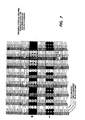
- Figure 6, Figure 7 and Figure 9 show three possible complementary grating arrays. It is noted that when any two masks are superimposed in registration there is no transmission.
Abstract
Description
- This invention relates to full color reproduction of a continuous tone color picture or image by the use of diffraction techniques.
- In the conventional color halftone picture, or, for example, in a color television picture, a continuous family of colors is simulated by the superposition or complementary juxtaposition of three "single color" halftones or "separations". These three colors are often referred to as the three "primaries". For example, there may be a "red" separation, a "blue" separation, and a "green" separation.
- In magazine or color print lithography, different primary color dots are deposited on the paper or other medium in various sized or diameters, so that the human eye integrates these dots and interprets them as various colors depending upon the dot mix. In photography, color negatives are provided which detect the various colors passing through the lens in a reversal process and, when printed, the various colors become viewable by the human eye. In all of these instances, however, the color perceived is due to either the reflective, transmissive, absorptive and/or radiant properties of the media (e.g. toner, ink, dyes, phosphors, pigments, etc.) involved, not the dispersive or diffractive properties.
- Our co-pending European application (D/85272) discloses that a full color image is created and is viewable in white light without the aid of colored inks, toner, sources, guns, or phosphors. A full color reproduction of a color picture, image or scene is realized by means of diffraction techniques. The output reproduction consists of a regular array of small planar diffraction gratings of multiple spatial frequencies configured in much the same way as conventional color halftone dots or color television pixels. Each individual grating by itself would produce a relatively monochromatic color sensation. A multiplicity of gratings are then superimposed or co-mingled in such a way as to produce any arbitrary color sensation. (In D/85272, no opaquing techniques are used and new separation masks and a new master must be created for each new original.)
- In accordance with the present application, a sheet of reflective or transmissive multiple diffraction gratings (which will appear much as a plain white canvas or paper) is prepared as in said copending application, with, however, no predisposition as for a particular image to be reproduced. The multiple reflective diffraction pixels are then selectively masked by, for example, black marks applied by xerographic or photographic means. The canvas is blackened or opaqued or rendered non-diffracting in such a way as to leave the appropriate grating or portion thereof exposed and functional for the correct color reproduction on a pixel-by-pixel basis.
- The present invention provides full colour reproduction of a continuous tone colour picture of image by the use of diffraction techniques in conjunction with at least two possible masking techniques. Both photographic and xerographic masking techniques will be treated here. The reproduction i.e., the device, consists of a regular array of small planar diffraction gratings of multiple spatial frequencies. The configuration of these arrays is analogous to similar arrays of color halftone dots or color television pixels. However, portions of these diffraction gratings, of either the reflective or transmissive variety, will be selectively blocked, masked or opaqued by either photographic or xerographic means in order to leave the appropriate gratings or portions thereof exposed for the correct color reproduction on a pixel-by-pixel basis. The full color image so created is viewed in white light.
- In accordance with one aspect of the invention there is a multiple diffraction grating comprising a plurality of areas on a single substrate, each of said areas having one of a plurality of diffraction grating frequencies, in a predetermined pattern such that the substrate appears white when viewed in white light.
- For a more complete understanding of the invention, reference may be had to the following detailed description of the invention in conjunction with the drawings wherein:
- Figure 1 shows the dispersion characteristic of three coplanar diffraction gratings of the present invention;
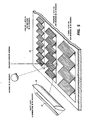
- Figure 2 is a schematic diagram of the present invention utilizing a Lloyd's mirror arrangement to record the multiple diffraction grating color reproduction;
- Figures 3A and 3B are schematic diagrams of the synthesis of the different grating frequencies utilizing the Lloyd's mirror arrangement;
- Figure 4 shows the spectral response to the gratings;
- Figure 5 is a schematic representation of a person viewing a multiple diffraction grating prepared in accordance with the present invention;
- Figure 6 is a schematic representation of a multiple diffraction grating in a horizontal stripe configuration of the present invention;
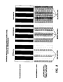
- Figure 7 is a schematic representation of a multiple diffraction grating in a vertical stripe configuration of the present invention;
- Figure 8 is a schematic representation of the fabrication of the white grating canvas (WGC) in a vertical configuration for the present invention
- Figure 9 is a schematic representation of three diffraction gratings arrayed in a hexagonal configuration.
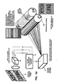
- Figure 10 is a representative drawing showing the overall principles of the present invention; and
- Figure 11 is a schematic representation of the registration of the grating-blocking transmission mask over the white grating canvas.
- In accordance with this invention, a regular array of three co-planar diffraction gratings is the device on which all full color reproductions will be formed. Under the proper conditions of illumination and viewing, this unique device will appear to be uniformly "white".
- The full color reproduction of an image which has been electronically captured will then be played-out onto this special material. On a pixel-by-pixel basis, the proper color rendition obtains by means of the selective opaquing of portions or elements of the three grating arrays.
- Figure 1 of the present application discloses one variation on the multiple diffraction grating technique of the present invention. F1, F2, and F3 are different reflective diffraction gratings all in the same plane, but not necessarily superimposed over one another.
- White light illumination is incident on this device near grazing incidence; e.g., at 85 degrees from the grating surface normal. One then finds three characteristic spectra associated with each of the three grating frequencies. The visible blue-to-red portions of the first-order spectra are shown for each grating in the figure. The gratings have been designed in such a way that a 20 degree viewing angel the (red) 630nm light from F1 coincides with both the (green) 530nm light from F2 and the (blue) 470nm light from F3.

- In the example described above, an observer positioned at an angle of 20 degrees from the grating normal will, with 85 degree illumination, see a new color which is the combination of the "red" portion of the incident spectrum dispersed by frequency F1 grating areas, the "green" portion of the spectrum dispersed by frequency F2 grating areas, and the "blue" portion of the incident spectrum dispersed by frequency F3 grating areas.
- A basic premise in this application is that a "white" color sensation can be produced through the proper combination of the red, green, and blue portions of spectra produced by these three different diffraction gratings. The actual color perceived due to any single grating alone will be dependent upon its grating spatial frequency, its size and shape, its diffraction efficiency and the viewing and illumination conditions. Reviewing the parameters which will influence the appearance of this device are: the particular observer,
grating frequency (lines per millimeter),
grating size and shape,
grating diffraction efficiency,
viewing angle,
viewer distance to device,
illumination spectral content,
illumination angle of incidence,
illumination source size.
- The second basic premise is that arbitrary color values can be fabricated through the judicious blackening or opaqueing of portions of the above described multiple diffraction gratings.
- The process by which a multiple diffraction grating full color reproduction is created is as follows:
- This step consists of two sub steps:
- 1: create grating separation masks
- 2: record gratings interferometrically through separation masks
- Fabrication of the three color separation masks - may be created from either conventional artwork, or may be computer-generated. In order to produce for example a vertically-oriented array of the three primary gratings, such as seen in Figure 7, the "separation mask" is straightforward and would look much as in Figure 8. These three transmission masks delineate which areas on the plate get which gratings. It is noted that in this application, the gratings will not overlap but will fall side by side on the plate.
- That is, as in television color techniques, certain areas are designated for "red grating" only, others for "green grating" only and the rest for "blue grating". These three separations are termed as being "complementary". It is noted that the spatial frequency of the halftoning screen is effectively reduced, that is, made coarser by this approach.
- Figure 6, Figure 7 and Figure 9 show three possible complementary grating arrays. It is noted that when any two masks are superimposed in registration there is no transmission.
- Fabrication of the WGC master is the next step. (When properly illuminated and viewed, this master, and all subsequent final replicas will appear as a uniformly bright white plane.) It is assumed that for purposes of the invention herein, that the master is recorded on a positive-working photoresist. In the particular embodiment described above, the diffraction gratings are all oriented in the same direction so as to disperse light in the same plane. Reference is made to Figure 5.
- The WGC consists of regular arrays of three different gratings. Figure 6, and Figure 7. These gratings are recorded in three serial interferometric exposures through different transmission masks.
- On a single properly
photosensitized plate 70, Figure 2, with the appropriate photosensitive coating, an interferometric diffraction grating exposure 60 (holographic) is made through each of the lithographic type transmission/separation masks 60 described above. A "Lloyd's mirror"arrangement 62 in conjunction with a vacuum platen, not shown, as shown in Figure 2 can be used to easily "impress" a different diffraction grating through each of the three masks. The masks are used in registered contact with the photosensitive coating. In this example, three masks would require three separate, registered, exposures. - The Lloyd's mirror arrangement is one method by which the gratings can be recorded. Such an arrangement creates interference between two monochromatic beams derived from the same laser. These interference patterns consist of very high spatial frequency "fringes", bands of light and dark. These illumination variations will ultimately be converted into periodic surface relief patterns which will exhibit diffraction effects. See Figure 3A and 3B.
- Proper chemical development results in a
WGC master plate 70 containing the three diffraction gratings as a surface relief pattern in the photoresist. This photresist-coated plate, without any reflection enhancing coatings will exhibit perceptible amounts of diffraction, amounts sufficient to enable the prediction of the performance of the final replicated product. - The exposure, development, and replication process will be optimized with respect to grating diffraction efficiency and with due consideration to the following parameters:
- grating type: either reflection of transmission,
- viewing and illumination angles,
- wavelength of interest. - Use standard electroforming techniques to create many reflective WGC replicas.
- Conventional nickel electroforming and embossing on clear or aluminized mylar techniques may now be applied to make white grating canvas replicas from the above master. These are the same techniques currently being used to make reflective hologram replicas. These flexible sheets of embossed mylar, either aluminized or clear, may now be used to create full-color image reproductions.
- On a pixel-by pixel basis, decompose color image to be reproduced into a collection of black marks. At the end of this step one has stored an electronic bit map file.
- Knowledge of the WGC design is necessary to insure that the mating array of black opaquing marks can correctly register with the WGC and provide the correct color rendition. Once the WGC design is defined, a computer program can be written which de-composes the original color content in the original scene on a WGC-pixel-by-pixel basis and decides where the black/opaque marks must fall. These marks, when registered with the WGC, act to block those grating primary colors or fractions thereof which do not contribute to the color value being rendered.
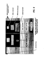
- The colored object or
scene 82 which is desired to be produced is first decomposed into three primary color signals by one of a few possible means, Figure 10. Acolor video camera 84 or color laser input scanner are two such means. In raster fashion, on a pixel by pixel basis, the color video camera decomposes the image or scene into three video signals, typically, red, green, and blue, representing the primary component colors. If desired, an electronic bit map file, perhaps of an intermediate nature may be generated here. - These three signals must then be reconstituted, i.e., processed, 90, with due consideration to: 1) the detailed design of the grating canvas that will be the playback media on which the black marks will be placed (a hexagonal array and a straight stripe array are two possible configurations shown in Figures 8 and Figure 9 and 2) the opaquing mechanism, 100 (either a laser raster output scanner or ROS, 94 mated to a xerographic marking engine, or a more conventional masking technique using photographic methods) which will selectively cause the blocking of the gratings or portions thereof. After this re-composition is done, the final bit map file representing a special array of black marks is created.
- In registration with the WGC, this file of opaque black marks is recorded or played back either directly onto the WGC using xerographic marking methods, or onto an intermediate clear material using photographic or xerographic marking methods. Then, in registration with the WGC, the intermediate clear material is superimposed and laminated to the WGC:
- After processing, this file is "played-out" to a raster output scanner 94 (ROS) mated to a xerographic marking engine, or a more conventional masking technique using photographic methods, Figure 10, in such a way as to 1) selectively mask those portions in the original scene that are truly black, and 2) selectively mask those elemental gratings whose primary color is not a component of the color in the original scene.
- By selectively occluding or masking the appropriate grating pixels, arbitrary colors, both spectral and non-spectral, can be created. The tonal value of a "cell", its brightness or luminance, can also be controlled in this way.
- For example, if any two of the three primary gratings are completely blocked within a cell, then only the one remaining monochromatic primary color will appears, i.e., red, green, or blue. If only one grating type is blocked, then the superposition of the remaining two primaries will give a color sensation within the subtractive primary family, that is cyan, magenta, or yellow. And, if no grating is blocked, the original "white canvas" will be apparent. See Figure 7.
- Obviously, a high degree of registration accuracy between the grating canvas and the xerographic marking engine is necessary in order to insure that the proper elemental gratings will be masked. One possible method by which this registration problem could be relaxed would be to record the blackening marks on a piece of clear material with registration marks rather than writing directly onto the white grating canvas. See Figure 11.
- This piece of clear material in then placed on top of the reflective white grating canvas or to the back of transmitting WGC, both of which will include registration marks identical to those on the WGC. The two are then laminated together.
- In so doing, the registration problem is removed from the marking engine.
- The final result when properly viewed and illuminated will, on a pixel-by-pixel basis, leave the same color value seen in the original image.
- In Figure 5, a linear, white light line source of
illumination 76 is shown. A long tungsten filament lamp would be such a source.Cylindrical collimation optics 74 are schematically shown. These would be designed to provide a collimated flood of white light onto thegrating halftone 78 at a single narrow angle of incidence. In Figure 5, the angle of incidence of the white light shown is approximately 85 degrees as calculated in the above examples. The WGC is of the reflective type; in the transmissive type, the illumination would be on the other side of the WGC. - Some very important applications of the present invention include:
- 1. Novel Halftone: Insofar as the novel halftone application described above would be virtually impossible to reproduce by conventional printing methods, such as lithography or xerography, it offers a unique method of counterfeiting protection.
Application of the device's principles and techniques described in the embodiment of this application makes viable the following scenario: a system can be designed which can reproduce conventional color images or scenes in the form of the novel grating produced color halftones. Key components of the system are 1) an input scanner/color separator, 2) a color reprocessor, 3) the opaquing engine (may be xerograpghic and would include laser output scanner) and 4) the white grating canvas material of either the reflective or transmitting type.
Since the appearance of this sort of halftone is strongly dependent upon the viewing conditions, specifically the spatial arrangement of the light source, halftone, and observer, this characteristic might also be exploited to unfold another layer of (metrological) information into the image. For example, if under the optimized viewing conditions, the scene shows a red colored stop sign, departures from the optimum viewing condition will cause the stop sign to change color. Since the change in color with viewing condition change can be predicted, this knowledge gives the viewer information as to where he stands relative to the optimum position. The perceived color of the sign thus gives the viewer feedback as to his position. Position, distance, angle, direction, and other metrological applications are further discussed below. - 2- Color synthesis: any visible color can, in principle, be synthesized by the addition of at least two spectral colors. By exploiting the dispersion characteristics of a plurality of linear diffraction gratings in a common plane as described above, virtually any color can be synthesized without the aid of inks, toners, special phosphors, etc.
- 3- Metrology: The characteristic one-to-one mapping or correlation between wavelength and dispersion angle of the linear diffraction grating is exploited for metrological purposes or applications. Normal spectral dispersion phenomena exhibited by a linear diffraction grating is used to encode metrological information such as angle, direction, and/or distance. The apparent color perceived by the observer is visual feedback information which can be correlated to the metrological parameter of interest.
- 4. Navigation, surveying, range finding, position sensing are some of the applications where direction and distance information could be encoded and decoded by spectral dispersion means described above. The Lloyd's mirror mastering technique described above is a particularly powerful way to synthesize these unique halftones with a wealth of spatially and spectrally detailed information.
- While the invention has been described with reference to specific embodiments, it will be understood by those skilled in the art that various changes may be made and equivalents may be substituted for elements thereof without departing from the scope of the invention. In addition, many modifications may be made without departing from the essential teachings of the invention.
Claims (15)
creating individual separation masks which delineate areas or zones dedicated to the reproduction of each of the primary colors,
exposing a single photosensitive plate with an interference pattern representative of a primary color through each of said individual separation masks to form multiple diffraction grating latent images on said photosensitive plate,
developing said photosensitive plate to convert said multiple diffraction grating latent images into surface relief diffraction gratings,
replicating said photosensitive plate where the replicas exhibit the same diffraction effects of said plate, and
selectively causing gratings or portions thereof on the plate or a replica to be masked in order to leave the gratings or portions thereof all or partially diffracting so as to further render said plate or said replica into a unique pattern of active and inactive diffraction gratings reproducing the original colors in the original scene, image or picture.
means for creating individual separation masks which delineate areas or zones dedicated to the reproduction of each of the primary colors,
means for exposing a single photosensitive plate with an interference pattern representative of a primary color through each of said individual separation masks to form multiple diffraction grating latent images on said photosensitive plate,
means for developing said photosensitive plate to convert said multiple diffraction grating latent images into surface relief diffraction gratings,
means for replicating said photosensitive plate where the replicas exhibit the same diffraction effects of said plate, and
means for selectively causing gratings or portions thereof on the plate or a replica to be masked in order to leave the gratings or portions thereof all or partially diffracting so as to further render said plate or said replica into a unique pattern of active and inactive diffraction gratings reproducing the original colors in the original scene, image or picture.
monochromatic laser illumination means (48) for providing a beam of light at a wavelength capable of exposing said photosensitive plate (70),
means for supporting said photosensitive plate and for placing said plate in a position to receive part of said laser light,
mirror means (62) in the path of the laser light for reflecting part of said laser light toward the photosensitive plate, such that the light reaching said photosensitive plate is a pattern of light and dark regions resulting from the interference between the direct and reflected laser light beams,
different separation mask means (60) for each primary color to be reproduced positioned in contact with said photosensitive plate, each of said mask means comprising transparent and opaque repeating patterns representative of the primary colors to be reproduced on said photosensitive plate, and
means for changing the angle between the interfering beams arriving at said plate through said separation masks and supporting means.
de-composing a color picture, image or scene into its primary color components, represented by electronic video signals,
re-processing said electronic video signals into a format consistent with the particular configuration of said multiple diffraction grating substrate, and
creating an array of marks from said electronic video signals which selectively causes gratings or portions thereof on the plate or a replica to be rendered non-functional.
recording said electronic video signals as an electrostatic latent image on a xerographic photoreceptor,
developing said latent image to leave opaque toner areas representative of said re-processed electronic video signals on said xerographic photoreceptor,
transfering said opaque toner areas in such a manner as to render the multiple diffaction gratings or portions thereof on the plate or a replica non-functional and thereby produce the full color reproduction of the original color image, picture or scene.
recording said electronic video signals as a latent image on a conventional photographic media,
developing said latent image to leave opaque areas representative of said re-processed electronic video signals on said photographic media,
transfering said opaque areas in such a manner as to render the multiple diffaction gratings or portions thereof on the plate or a replica non-functional and thereby produce the full color reproduction of the original color image, picture or scene.
means (84) for de-composing a color picture, image or scene into its primary color components, represented by electronic video signals,
means (90) for re-processing said electronic video signals into a format consistent with the particular configuration of said multiple diffraction grating substrate, and
means for creating an array of marks from said electronic video signals which selectively causes gratings or portions thereof on the plate or a replica to be rendered non-functional.
Applications Claiming Priority (2)
| Application Number | Priority Date | Filing Date | Title |
|---|---|---|---|
| US846535 | 1986-03-31 | ||
| US07/846,535 US4788116A (en) | 1986-03-31 | 1986-03-31 | Full color images using multiple diffraction gratings and masking techniques |
Publications (2)
| Publication Number | Publication Date |
|---|---|
| EP0240262A2 true EP0240262A2 (en) | 1987-10-07 |
| EP0240262A3 EP0240262A3 (en) | 1989-05-10 |
Family
ID=25298210
Family Applications (1)
| Application Number | Title | Priority Date | Filing Date |
|---|---|---|---|
| EP87302660A Withdrawn EP0240262A3 (en) | 1986-03-31 | 1987-03-27 | Diffraction grating color imaging |
Country Status (3)
| Country | Link |
|---|---|
| US (1) | US4788116A (en) |
| EP (1) | EP0240262A3 (en) |
| JP (1) | JPS62232616A (en) |
Cited By (18)
| Publication number | Priority date | Publication date | Assignee | Title |
|---|---|---|---|---|
| EP0357837A2 (en) * | 1988-09-07 | 1990-03-14 | Toppan Printing Co., Ltd. | Method for producing a display with a diffraction grating pattern and a display produced by the method |
| JPH0289081A (en) * | 1988-09-26 | 1990-03-29 | Dainippon Printing Co Ltd | Holographic color filter |
| GB2223861A (en) * | 1988-10-14 | 1990-04-18 | Trade & Industry Secretary Of | Making a product having a multiplicity of fine lines |
| WO1990007133A1 (en) * | 1988-12-19 | 1990-06-28 | Reserve Bank Of Australia | Diffraction grating |
| WO1991003747A1 (en) * | 1989-09-04 | 1991-03-21 | Commonwealth Scientific And Industrial Research Organisation | Diffraction grating and method of manufacture |
| EP0467601A2 (en) * | 1990-07-12 | 1992-01-22 | Applied Holographics Corporation | Holographic diffraction grating patterns and methods for creating the same |
| EP0497292A2 (en) * | 1991-01-29 | 1992-08-05 | Toppan Printing Co., Ltd. | Display having diffraction grating pattern |
| EP0534616A2 (en) * | 1991-08-29 | 1993-03-31 | Fujitsu Limited | Holographic recording apparatus and holographic optical element |
| GB2260203A (en) * | 1991-10-04 | 1993-04-07 | Marconi Gec Ltd | Transmissive colour display system illuminated using a holographic element |
| WO1993018419A1 (en) * | 1992-03-12 | 1993-09-16 | Commonwealth Scientific And Industrial Research Organisation | Security diffraction grating with special optical effects |
| WO1994028444A1 (en) * | 1993-05-25 | 1994-12-08 | Commonwealth Scientific And Industrial Research Organisation | Multiple image diffractive device |
| WO1995004948A1 (en) * | 1993-08-06 | 1995-02-16 | Commonwealth Scientific And Industrial Research Organisation | A diffractive device |
| AU673100B2 (en) * | 1993-08-06 | 1996-10-24 | Commonwealth Scientific And Industrial Research Organisation | A diffractive device |
| AU679664B2 (en) * | 1993-08-06 | 1997-07-03 | Commonwealth Scientific And Industrial Research Organisation | A diffractive device |
| US5912767A (en) * | 1993-11-23 | 1999-06-15 | Commonwealth Scientific And Industrial Research Organisation | Diffractive indicia for a surface |
| US6088161A (en) * | 1993-08-06 | 2000-07-11 | The Commonwealth Of Australia Commonwealth Scientific And Industrial Research Organization | Diffractive device having a surface relief structure which generates two or more diffraction images and includes a series of tracks |
| EP0769179B2 (en) † | 1994-07-02 | 2004-12-29 | LEONHARD KURZ GMBH & CO. | Structural assembly with diffractive properties |
| WO2015167363A1 (en) * | 2014-04-29 | 2015-11-05 | Федеральное Государственное Унитарное Предприятие "Гознак" (Фгуп "Гознак") | Method for producing combined black-and-white and full-color personalized image on multi-layer structure |
Families Citing this family (45)
| Publication number | Priority date | Publication date | Assignee | Title |
|---|---|---|---|---|
| ES2116981T3 (en) * | 1989-03-16 | 1998-08-01 | Dainippon Printing Co Ltd | FILTER PRODUCTION AND DUPLICATION PROCEDURE, AND PRODUCTION PROCEDURE OF PHOTOSENSITIVE ORGANS PROVIDED WITH THESE FILTERS. |
| US5266986A (en) * | 1989-06-26 | 1993-11-30 | Kobel John O | System and method for providing enlarged prints of color transparencies and negatives |
| US5396839A (en) * | 1992-09-23 | 1995-03-14 | Col1Or | Apparatus and method for printing color images |
| US5519210A (en) * | 1993-05-13 | 1996-05-21 | Gretag Aktiengesellschaft | Apparatus and a process for recording photometric data that is positioned in succession or in adjacent fashion on a page-like or strip-like print |
| US5818717A (en) * | 1993-06-02 | 1998-10-06 | Trintec Industries Inc. | Automated small volume production of instrument faces |
| EP0992020B1 (en) * | 1996-12-12 | 2003-03-19 | OVD Kinegram AG | Surface pattern |
| US7667895B2 (en) | 1999-07-08 | 2010-02-23 | Jds Uniphase Corporation | Patterned structures with optically variable effects |
| US7604855B2 (en) | 2002-07-15 | 2009-10-20 | Jds Uniphase Corporation | Kinematic images formed by orienting alignable flakes |
| US7517578B2 (en) * | 2002-07-15 | 2009-04-14 | Jds Uniphase Corporation | Method and apparatus for orienting magnetic flakes |
| US7047883B2 (en) | 2002-07-15 | 2006-05-23 | Jds Uniphase Corporation | Method and apparatus for orienting magnetic flakes |
| US11768321B2 (en) | 2000-01-21 | 2023-09-26 | Viavi Solutions Inc. | Optically variable security devices |
| US6730443B2 (en) * | 2000-02-28 | 2004-05-04 | University Of Tennessee Research Foundation | Patterning methods and systems using reflected interference patterns |
| US20030017421A1 (en) * | 2001-07-18 | 2003-01-23 | Miri Park | Holographic grating fabrication using mirror with surface curvature |
| US6902807B1 (en) * | 2002-09-13 | 2005-06-07 | Flex Products, Inc. | Alignable diffractive pigment flakes |
| US7625632B2 (en) | 2002-07-15 | 2009-12-01 | Jds Uniphase Corporation | Alignable diffractive pigment flakes and method and apparatus for alignment and images formed therefrom |
| US7221512B2 (en) * | 2002-01-24 | 2007-05-22 | Nanoventions, Inc. | Light control material for displaying color information, and images |
| US7934451B2 (en) | 2002-07-15 | 2011-05-03 | Jds Uniphase Corporation | Apparatus for orienting magnetic flakes |
| US11230127B2 (en) | 2002-07-15 | 2022-01-25 | Viavi Solutions Inc. | Method and apparatus for orienting magnetic flakes |
| US9458324B2 (en) | 2002-09-13 | 2016-10-04 | Viava Solutions Inc. | Flakes with undulate borders and method of forming thereof |
| US7241489B2 (en) * | 2002-09-13 | 2007-07-10 | Jds Uniphase Corporation | Opaque flake for covert security applications |
| US7645510B2 (en) | 2002-09-13 | 2010-01-12 | Jds Uniphase Corporation | Provision of frames or borders around opaque flakes for covert security applications |
| US7674501B2 (en) | 2002-09-13 | 2010-03-09 | Jds Uniphase Corporation | Two-step method of coating an article for security printing by application of electric or magnetic field |
| US8025952B2 (en) | 2002-09-13 | 2011-09-27 | Jds Uniphase Corporation | Printed magnetic ink overt security image |
| US9164575B2 (en) | 2002-09-13 | 2015-10-20 | Jds Uniphase Corporation | Provision of frames or borders around pigment flakes for covert security applications |
| US7258915B2 (en) * | 2003-08-14 | 2007-08-21 | Jds Uniphase Corporation | Flake for covert security applications |
| US7550197B2 (en) | 2003-08-14 | 2009-06-23 | Jds Uniphase Corporation | Non-toxic flakes for authentication of pharmaceutical articles |
| JP4563213B2 (en) * | 2004-02-25 | 2010-10-13 | 大日本印刷株式会社 | An optical diffraction structure including an optical diffraction structure replicated by the optical diffraction structure replication method and the replication method. |
| TWI402106B (en) | 2005-04-06 | 2013-07-21 | Jds Uniphase Corp | Dynamic appearance-changing optical devices (dacod) printed in a shaped magnetic field including printable fresnel structures |
| CA2564764C (en) | 2005-10-25 | 2014-05-13 | Jds Uniphase Corporation | Patterned optical structures with enhanced security feature |
| CA2570965A1 (en) | 2005-12-15 | 2007-06-15 | Jds Uniphase Corporation | Security device with metameric features using diffractive pigment flakes |
| US10343436B2 (en) | 2006-02-27 | 2019-07-09 | Viavi Solutions Inc. | Security device formed by printing with special effect inks |
| CA2592667C (en) | 2006-07-12 | 2014-05-13 | Jds Uniphase Corporation | Stamping a coating of cured field aligned special effect flakes and image formed thereby |
| US7894109B2 (en) | 2006-08-01 | 2011-02-22 | Xerox Corporation | System and method for characterizing spatial variance of color separation misregistration |
| US8274717B2 (en) | 2006-08-01 | 2012-09-25 | Xerox Corporation | System and method for characterizing color separation misregistration |
| US8270049B2 (en) | 2006-08-01 | 2012-09-18 | Xerox Corporation | System and method for high resolution characterization of spatial variance of color separation misregistration |
| US8314989B1 (en) | 2006-12-29 | 2012-11-20 | Lightsmyth Technologies Inc. | Decorative, ornamental, or jewelry articles having arrays of diffraction gratings |
| US7826095B2 (en) | 2007-01-16 | 2010-11-02 | Xerox Corporation | System and method for estimating color separation misregistration utilizing frequency-shifted halftone patterns that form a moiré pattern |
| US8228559B2 (en) | 2007-05-21 | 2012-07-24 | Xerox Corporation | System and method for characterizing color separation misregistration utilizing a broadband multi-channel scanning module |
| US7630672B2 (en) | 2007-05-21 | 2009-12-08 | Xerox Corporation | System and method for determining and correcting color separation registration errors in a multi-color printing system |
| US8270079B1 (en) | 2007-11-15 | 2012-09-18 | Lightsmyth Technologies Inc. | Decorative, ornamental, or jewelry articles having diffraction gratings |
| JP2009193069A (en) | 2008-02-13 | 2009-08-27 | Jds Uniphase Corp | Medium for laser printing including optical special effect flake |
| JP2012042704A (en) * | 2010-08-19 | 2012-03-01 | Toppan Printing Co Ltd | Image display body |
| JP5637371B2 (en) * | 2010-09-24 | 2014-12-10 | 凸版印刷株式会社 | Image display body, transfer foil, and labeled article |
| DK2802450T3 (en) | 2012-01-12 | 2019-03-25 | Viavi Solutions Inc | Article with a dynamic frame consisting of decorated pigment flakes |
| JP2018120010A (en) * | 2017-01-23 | 2018-08-02 | 凸版印刷株式会社 | Color image print medium, article including the same, and printing method |
Citations (4)
| Publication number | Priority date | Publication date | Assignee | Title |
|---|---|---|---|---|
| US3078338A (en) * | 1958-12-24 | 1963-02-19 | Gen Electric | Orthogonal diffraction gratings for color reproduction |
| US3743507A (en) * | 1970-10-23 | 1973-07-03 | Rca Corp | Recording of a continuous tone focused image on a diffraction grating |
| US3997243A (en) * | 1975-02-20 | 1976-12-14 | Xerox Corporation | Color image reproduction system |
| US4153457A (en) * | 1978-01-16 | 1979-05-08 | Minnesota Mining And Manufacturing Company | High resolution halftone microimages and method therefor |
Family Cites Families (5)
| Publication number | Priority date | Publication date | Assignee | Title |
|---|---|---|---|---|
| US817569A (en) * | 1905-10-19 | 1906-04-10 | Herbert E Ives | Diffraction color photograph and mode of making same. |
| US3947105A (en) * | 1973-09-21 | 1976-03-30 | Technical Operations, Incorporated | Production of colored designs |
| US3957354A (en) * | 1975-02-03 | 1976-05-18 | Rca Corporation | Diffractive subtractive color filtering technique |
| US4017158A (en) * | 1975-03-17 | 1977-04-12 | E. I. Du Pont De Nemours And Company | Spatial frequency carrier and process of preparing same |
| CH616253A5 (en) * | 1977-06-21 | 1980-03-14 | Landis & Gyr Ag |
-
1986
- 1986-03-31 US US07/846,535 patent/US4788116A/en not_active Expired - Fee Related
-
1987
- 1987-03-24 JP JP62068175A patent/JPS62232616A/en active Pending
- 1987-03-27 EP EP87302660A patent/EP0240262A3/en not_active Withdrawn
Patent Citations (4)
| Publication number | Priority date | Publication date | Assignee | Title |
|---|---|---|---|---|
| US3078338A (en) * | 1958-12-24 | 1963-02-19 | Gen Electric | Orthogonal diffraction gratings for color reproduction |
| US3743507A (en) * | 1970-10-23 | 1973-07-03 | Rca Corp | Recording of a continuous tone focused image on a diffraction grating |
| US3997243A (en) * | 1975-02-20 | 1976-12-14 | Xerox Corporation | Color image reproduction system |
| US4153457A (en) * | 1978-01-16 | 1979-05-08 | Minnesota Mining And Manufacturing Company | High resolution halftone microimages and method therefor |
Non-Patent Citations (2)
| Title |
|---|
| OPTICS COMMUNICATIONS, vol. 18, no. 3, August 1976, pages 292-297; M.T. GALE: "Sinusoidal relief gratings for zero-order reconstruction of black-and-white images" * |
| OPTICS COMMUNICATIONS, vol. 18, no. 3, August 1976, pages 298-303; K. KNOP: "Color pictures using the zero diffraction order of phase grating structures" * |
Cited By (30)
| Publication number | Priority date | Publication date | Assignee | Title |
|---|---|---|---|---|
| EP0585966A2 (en) * | 1988-09-07 | 1994-03-09 | Toppan Printing Co., Ltd. | Method for producing a display with a diffraction grating pattern and a display produced by the method |
| EP0357837A3 (en) * | 1988-09-07 | 1991-10-16 | Toppan Printing Co., Ltd. | Method for producing a display with a diffraction grating pattern and a display produced by the method |
| EP0585966A3 (en) * | 1988-09-07 | 1994-04-13 | Toppan Printing Co., Ltd. | Method for producing a display with a diffraction grating pattern and a display produced by the method |
| EP0357837A2 (en) * | 1988-09-07 | 1990-03-14 | Toppan Printing Co., Ltd. | Method for producing a display with a diffraction grating pattern and a display produced by the method |
| JPH0289081A (en) * | 1988-09-26 | 1990-03-29 | Dainippon Printing Co Ltd | Holographic color filter |
| GB2223861A (en) * | 1988-10-14 | 1990-04-18 | Trade & Industry Secretary Of | Making a product having a multiplicity of fine lines |
| WO1990007133A1 (en) * | 1988-12-19 | 1990-06-28 | Reserve Bank Of Australia | Diffraction grating |
| WO1991003747A1 (en) * | 1989-09-04 | 1991-03-21 | Commonwealth Scientific And Industrial Research Organisation | Diffraction grating and method of manufacture |
| EP0467601A3 (en) * | 1990-07-12 | 1992-03-04 | Applied Holographics Corporation | Holographic diffraction grating patterns and methods for creating the same |
| US5291317A (en) * | 1990-07-12 | 1994-03-01 | Applied Holographics Corporation | Holographic diffraction grating patterns and methods for creating the same |
| EP0467601A2 (en) * | 1990-07-12 | 1992-01-22 | Applied Holographics Corporation | Holographic diffraction grating patterns and methods for creating the same |
| EP0497292A3 (en) * | 1991-01-29 | 1994-02-16 | Toppan Printing Co Ltd | |
| EP0497292A2 (en) * | 1991-01-29 | 1992-08-05 | Toppan Printing Co., Ltd. | Display having diffraction grating pattern |
| US5892597A (en) * | 1991-08-29 | 1999-04-06 | Fujitsu Limited | Holographic recording apparatus and holographic optical element |
| EP0534616A2 (en) * | 1991-08-29 | 1993-03-31 | Fujitsu Limited | Holographic recording apparatus and holographic optical element |
| EP0534616B1 (en) * | 1991-08-29 | 1997-10-29 | Fujitsu Limited | Holographic recording apparatus and holographic optical element |
| GB2260203A (en) * | 1991-10-04 | 1993-04-07 | Marconi Gec Ltd | Transmissive colour display system illuminated using a holographic element |
| GB2260203B (en) * | 1991-10-04 | 1994-09-07 | Marconi Gec Ltd | Colour display system |
| WO1993018419A1 (en) * | 1992-03-12 | 1993-09-16 | Commonwealth Scientific And Industrial Research Organisation | Security diffraction grating with special optical effects |
| WO1994028444A1 (en) * | 1993-05-25 | 1994-12-08 | Commonwealth Scientific And Industrial Research Organisation | Multiple image diffractive device |
| US6342969B1 (en) | 1993-05-25 | 2002-01-29 | Commonwealth Scientific/Industrial Research Organization | Multiple image diffractive device |
| US5909313A (en) * | 1993-05-25 | 1999-06-01 | Commonwealth Scientific And Industrial Research Organisation | Multiple image diffractive device |
| AU673100B2 (en) * | 1993-08-06 | 1996-10-24 | Commonwealth Scientific And Industrial Research Organisation | A diffractive device |
| AU679664B2 (en) * | 1993-08-06 | 1997-07-03 | Commonwealth Scientific And Industrial Research Organisation | A diffractive device |
| US6088161A (en) * | 1993-08-06 | 2000-07-11 | The Commonwealth Of Australia Commonwealth Scientific And Industrial Research Organization | Diffractive device having a surface relief structure which generates two or more diffraction images and includes a series of tracks |
| EP0766103B1 (en) * | 1993-08-06 | 2001-05-23 | Commonwealth Scientific And Industrial Research Organisation | A diffractive device |
| WO1995004948A1 (en) * | 1993-08-06 | 1995-02-16 | Commonwealth Scientific And Industrial Research Organisation | A diffractive device |
| US5912767A (en) * | 1993-11-23 | 1999-06-15 | Commonwealth Scientific And Industrial Research Organisation | Diffractive indicia for a surface |
| EP0769179B2 (en) † | 1994-07-02 | 2004-12-29 | LEONHARD KURZ GMBH & CO. | Structural assembly with diffractive properties |
| WO2015167363A1 (en) * | 2014-04-29 | 2015-11-05 | Федеральное Государственное Унитарное Предприятие "Гознак" (Фгуп "Гознак") | Method for producing combined black-and-white and full-color personalized image on multi-layer structure |
Also Published As
| Publication number | Publication date |
|---|---|
| JPS62232616A (en) | 1987-10-13 |
| EP0240262A3 (en) | 1989-05-10 |
| US4788116A (en) | 1988-11-29 |
Similar Documents
| Publication | Publication Date | Title |
|---|---|---|
| US4788116A (en) | Full color images using multiple diffraction gratings and masking techniques | |
| US4737448A (en) | Color images formed by multiple diffraction gratings | |
| EP0357837B1 (en) | Method for producing a display with a diffraction grating pattern and a display produced by the method | |
| US3947105A (en) | Production of colored designs | |
| US4062628A (en) | Black-and-white diffractive subtractive light filter | |
| US20070064290A1 (en) | Device for making a reflection hologram | |
| US5283140A (en) | Halftone image screening array of parallel lines with effective maximum and minimum optical density and method of generating a halftone image utilizing the screening array | |
| US4968064A (en) | Variable color print | |
| US7806499B2 (en) | Complex pointillistic printing | |
| US4081828A (en) | Method for halftone reproduction of continuous tone images | |
| JPH1115104A (en) | Color negative photographic printing medium for copying limitation | |
| US4108654A (en) | Color electrophotographic process employing a document screen | |
| CA1211978A (en) | Integrated photoscreen for making a halftone reproduction printing plate from a photograph | |
| CA1116897A (en) | High resolution halftone microimages and method therefor | |
| US4269915A (en) | Information carrier original for zero order diffraction projection | |
| US5074597A (en) | Computerized method of generating film masters for embossing and printing color images | |
| WO1988005387A1 (en) | Variable color print and method of making same | |
| CA1124122A (en) | Information carrier and process for its manufacture | |
| KR920005770B1 (en) | Device for producing separation film for print reprodution | |
| US5180305A (en) | Process color separation guide for color transparencies | |
| CA1062762A (en) | Color dot screen for electro photography | |
| US6163382A (en) | Devices and methods for offset and similar printing systems | |
| US4281049A (en) | Color separation transparency and process for the preparation thereof | |
| Knop et al. | Color Recording And Display By Zero Order Diffraction | |
| US4157220A (en) | Technique for recording micropicture-information on a diffractive subtractive filter embossing master |
Legal Events
| Date | Code | Title | Description |
|---|---|---|---|
| PUAI | Public reference made under article 153(3) epc to a published international application that has entered the european phase |
Free format text: ORIGINAL CODE: 0009012 |
|
| AK | Designated contracting states |
Kind code of ref document: A2 Designated state(s): DE FR GB |
|
| PUAL | Search report despatched |
Free format text: ORIGINAL CODE: 0009013 |
|
| AK | Designated contracting states |
Kind code of ref document: A3 Designated state(s): DE FR GB |
|
| 17P | Request for examination filed |
Effective date: 19891025 |
|
| 17Q | First examination report despatched |
Effective date: 19920130 |
|
| STAA | Information on the status of an ep patent application or granted ep patent |
Free format text: STATUS: THE APPLICATION HAS BEEN WITHDRAWN |
|
| 18W | Application withdrawn |
Withdrawal date: 19930227 |
|
| RIN1 | Information on inventor provided before grant (corrected) |
Inventor name: HOCHBERG, ERIC B. |