EP0230572A1 - A method of manufacturing ion-selective electrodes for analyzing selected ions in solution - Google Patents
A method of manufacturing ion-selective electrodes for analyzing selected ions in solution Download PDFInfo
- Publication number
- EP0230572A1 EP0230572A1 EP86116841A EP86116841A EP0230572A1 EP 0230572 A1 EP0230572 A1 EP 0230572A1 EP 86116841 A EP86116841 A EP 86116841A EP 86116841 A EP86116841 A EP 86116841A EP 0230572 A1 EP0230572 A1 EP 0230572A1
- Authority
- EP
- European Patent Office
- Prior art keywords
- solution
- layer
- electrode
- diaphragm
- ion
- Prior art date
- Legal status (The legal status is an assumption and is not a legal conclusion. Google has not performed a legal analysis and makes no representation as to the accuracy of the status listed.)
- Granted
Links
Images
Classifications
-
- G—PHYSICS
- G01—MEASURING; TESTING
- G01N—INVESTIGATING OR ANALYSING MATERIALS BY DETERMINING THEIR CHEMICAL OR PHYSICAL PROPERTIES
- G01N27/00—Investigating or analysing materials by the use of electric, electrochemical, or magnetic means
- G01N27/26—Investigating or analysing materials by the use of electric, electrochemical, or magnetic means by investigating electrochemical variables; by using electrolysis or electrophoresis
- G01N27/28—Electrolytic cell components
- G01N27/30—Electrodes, e.g. test electrodes; Half-cells
- G01N27/333—Ion-selective electrodes or membranes
- G01N27/3335—Ion-selective electrodes or membranes the membrane containing at least one organic component
Definitions
- the invention relates to the manufacture of laminar electrodes comprising a selectively ion-permeable diaphragm and used for determining specific ions in aqueous solution, e.g. Na , K + , Mg ,Ca , Cl , etc., inter alia in biological fluids.
- aqueous solution e.g. Na , K + , Mg ,Ca , Cl , etc.
- the electrodes usually comprise an internal electrochemical reference half-cell at a stable potential and adapted, in conjunction with an external reference electrode immersed simultaneously with the measuring electrode in a solution to be analyzed, to form an electrochemical cell of a potential dependent on the presence of a given ion in the solution.
- an assembly of this kind comprising two electrodes and a connecting electrolyte is described as a "battery”.
- a battery produces current in contrast to the present cell, which delivers a potential only in order to avoid irreversibility conditions.
- Electrodes in the form of dry multi-laminates comprising, in the following order, an insulating support, a metal electrically conductive layer covered with an insoluble salt of the metal, a part of the layer being used as a terminal for connection to an electrometer, a reference electrolyte and an ion-selective diaphragm for selectively measuring a given ion.
- the assembly made up of the metal layer, the insoluble salt and the reference electrolyte constitutes the internal reference half-cell at stable potential.
- the assembly can be replaced by a conductive layer covered with a redox system, e.g. the quinone-hydroquinone couple, which system likewise comprises an internal reference cell at stable potential.
- the ionically selective diaphragm usually comprises a plasticizer and a hydrophobic matrix containing in dispersion an ionophoric substance, i.e. one of use for selectively detecting a given ion to the exclusion of any other ions in the solution to be analyzed, compare W. E. MORF et al., Ion-Selective Electrodes in Analytical Chemistry, Vol.I, FRIESER Editor, Plenum Press (1981), pp 221 ff.
- MILES Magnetic Ink Characterization
- Docunent GB-A-2 106 253 (FUJI) likewise describes an electrode for selectively deternining ions, the electrode being a laminate comprising an insulating support, a conductive layer covered with an insoluble salt of the metal forming the conductive layer, and a hydrophobic layer of an ion-selective nateriai (ISM) covering the rest.
- ISM ion-selective nateriai
- Document US-A-4 454 007 likewise describes a laminar ion-selective electrode having the following structure: a baseplate of insulating material, a layer of conductive material, a layer comprising powdered carbon dispersed in a dielectric polymer, and finally an ion-selective diaphragm made of material which penetrates with the material in the preceding layer at their junction plane.
- the previously-described electrodes are used as follows.
- a drop thereof is deposited on to the diaphragm, which has selective ion permeability, and the drop is also placed in contact with the external reference electrode, e.g. via a salt bridge, the terminals of the ion-selective electrode and the reference electrode being connected to a suitable electrometer for reading the potential.
- the external reference electrode may be similar to or identical with the measuring electrode, and the external reference potential can be supplied either by a standard solution deposited simultaneously with the solution to be analyzed (in which case the solutions make contact by diffusion into a porous element situated between the deposition areas) or by a fixed reference element (the salt bridge for example) forming part of the external reference electrode.
- the ISM diaphragm In order to locate and fix the position of the drop of solution to be analyzed (and also the drop of standard solution when necessary) the ISM diaphragm is usually covered with a layer of insulating, waterproof material formed with compartments or windows giving access to only that portion of the ISM layer facing the window.
- This system prevents the drop spreading on the surface of the I SM layer and can also be used for selecting a fixed preset quantity of liquid for measuring, since the capacity of the compartments is kept constant from one electrode to the other.
- Electrodes of this kind are capable of producing short-circuits as a result either of inter-layer diffusion of aqueous liquids or if the liquids accidentally come into contact with the edges of the electrodes. Attempts have been made to obviate these defects by various means, e.g. by tightly sealing the edges of the electrodes (GB-A-2 106 253) or by grooving the conductive layer so as to divide it into zones and filling the grooves with ISM material (GB-A-2 121 183). According to the invention, as summarised in claim 1, the risk of short-circuits has been obviated by completely tightly sealing the ion selective (ISM) diaphragm to the impermeable hydrophobic mask covering the electrode. The tight seal between these components completely prevents any inter-layer diffusion of aqueous liquids and eliminates the risk of short-circuits.
- ISM ion selective
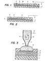
- Fig. 1 shows an electrode comprising the following components in succession; an insulating base plate or sheet 1, an electrically conductive layer 2 co-operating with the next layer 3 to form a redox system, an internal electrochemical reference cell at stable potential, and finally a mask 4 covering the rest and made of hydrophobic insulating material and formed with two windows 4a and 4b.
- Window 4b is for establishing electric contact (e.g. via a conductor 5) and thus provides a contact terminal connecting the conductive layer 2 to one terminal of an electrometer (not shown).
- the electrode also comprises a diaphragm 6 disposed in window 4a and in contact with reference element 3.
- Diaphragm 6 selects specific ions, e.g. K + ions, and is secured in completely sealing-tight manner to the walls of the mask as a result of inter-diffusion of the (polymer) binder of diaphragm 6 and the material of mask 4. This interpenetration results from the method of manufacture as defined in claim 1 and as will be detailed later.
- the configuration of the variant in Fig. 2 is similar to F ig. 1, and consequently like elements are denoted by like reference numbers.
- This variant differs with regard to the nature of the reference half-cell at stable potential.
- the cell in addition to the conductive metal base, the cell comprises a layer 7 of an insoluble salt of the conductive-base metal and a reference electrolyte where the anion is identical with that of the insoluble salt and the cation identical with that which is to be measured in the analyzed substance.
- the conductive base 2 can be silver
- the insoluble salt can be a silver halide such as AgCl
- the electrolyte 8 can be a potassium halide, e.g. KC1.
- Fig. 3 illustrates a method of analyzing a solution 10 using the electrode in Fig. 2 (the first variant will of course be the same in operation).
- a drop 10 of the solution for analysis is taken and deposited in the compartment 4a formed in mask 4, so that it makes contact with the ion-selective diaphragm 6.
- contact is made with an electrometer via a coupling means, e.g. a pipette 11 having a porous glass tip 12 and a reference electrode 13 (e.g. a silver plate covered with AgCl and immersed in a reference electrode 14 , e.g. KC1 N).
- a coupling means e.g. a pipette 11 having a porous glass tip 12 and a reference electrode 13 (e.g. a silver plate covered with AgCl and immersed in a reference electrode 14 , e.g. KC1 N).
- contact with the electrometer is made via conductor 5 and also via a conductor 15 connected to the reference electrode 13.
- the potential of the electrochemical cell formed by the aforementioned elements - is measured and, if the internal reference potential (elements 2, 7 and 8) and the concentration of the reference solution 14 are known, it is possible to calculate the concentration of chosen ions in solution 10 by using the NERNST relation (see e.g. "Physical Chemistry” by W. J. Moore, Prentice-Hall, Inc. 3e ed. London 1962, p.389).
- the electrodes according to the invention can be constructed by using an insulating base 1 comprising a shee;, film or plate of a polymer such as PVC, mylar, cellulose acetate, polycarbonates, plexiglass, polystyrene, etc.
- a polymer such as PVC, mylar, cellulose acetate, polycarbonates, plexiglass, polystyrene, etc.
- the nature of the insulating base is not critical provided it does not interfere with the other electrode components, and it can be made from conventional materials and by conventional methods.
- the conductive layer 2 can be made from a metal sheet or film, e.g. Fe, Pt, Ag, Cu, Ni, Co, etc., inter alia if the layer is coated with an insoluble salt 7 of the base metal.
- layer 2 can comprise a sheet of silver between 10 and 100 ⁇ m thick or a silver deposit produced by "electroless" techniques or by vaporization in vacuo or by using a silver paint, e.g. Type P-720 or P-750 produced by JOHNSON-MATTHEY, England.
- An aforementioned silver layer can be coated with an insoluble silver salt, e.g. silver chloride, by oxidation by conventional methods, e.g. chemically or by anodization in the presence of HC1 and by conventional methods.
- the internal reference-potential element is a redox couple
- the conductive layer in addition to a metal as previously described, can comprise other conductive substances such as carbon powder or fibres (in a polymer) or a porous carbon sheet.
- the redox reference system can be a conventional redox system such as quin- hydrone or ferrous/ferric couples such as Fe(CN) 6 -4 / Fe(CN) 6 3 or cobaltous/cobaltic. e.g.
- Prussian blue it is also (unexpectedly) possible to use Prussian blue.
- the system is prepared by immersing the conductive layer in an FeCl 3 solution and subsequently in an alkaline ferrocyanide solution.
- the result is an adhesive layer of Prussian blue between 0.1 and 10 ⁇ m thick and having a potential (on an Fe, Ni, Co or carbon support) which is particularly stable.
- binders suitable for redox couples gelatine, polyvinyl alcohol, polyacrylamide, polyvinyl pyrrolidone, etc.
- an electrolyte such as KC1 dispersed in a hydrophilic polymer such as gelatine or polyhydroxyacrylic acid.
- an electrolyte such as KC1 dispersed in a hydrophilic polymer such as gelatine or polyhydroxyacrylic acid.
- a layer of electrolyte which is completely dry and without a hydrophilic binder, e.g. KCl, NaCl or another alkali-metal or alkaline earth salt, etc., obtained by complete evaporation and drying of a solution of one of these salts.
- KCl, NaCl or another alkali-metal or alkaline earth salt, etc. obtained by complete evaporation and drying of a solution of one of these salts.
- the possibility of using a dehydrated alkaline salt as the stable-potential reference electrolyte is a surprising and unexpected development, since the resulting electrode rapidly stabilizes and has a very short response time.
- the mask 4 covering the electrode can be made of a hydrophobic polymer such as PVC, polyacrylate, polystyrene, polycarbonate, etc.
- the mask does not require any complicated device for positioning it, since the sealing-tightness of the operating zone of the electrode does not depend on the actual mask over the other components of the laminate, but rather on the uniformity of the material joining the mask 4 to the ion-selective diaphragm 6.
- the mask can be a single sheet of adhesive polymer applied by hot or cold pressure on to the other components of the laminate and intimately following their shape.
- the "solvent casting" technique can be used.
- Diaphragm 6 comprises a binder, a plasticizer and an ionophore.
- ionophore will depend on the nature of the ions to be deternined, e.g. valinomycin for potassium, methyl-monensin for sodium, certain phosphonic esters for calcium, etc.
- Detailed information on the required ionophores, depending on the chosen type of analysis, will be found amomg the previous citations, inter alia document US-A-4 454 007.
- the binder for the ionophoric compound can be a polymer such as polyvinyl chloride (PVC), polystyrene, polyacrylates, polycarbonates, polyesters (polyethylene terephthalate), etc.
- PVC polyvinyl chloride
- the polymer chosen for the binder of diaphragm 6 will be identical with the material in the mask, e.g. PVC.
- a solution of constituents thereof should be applied in a solvent in which the mask material is also soluble.
- the plasticizer used in the diaphragm can be one of the conventional plasticizers such as dimethylphthalate, dioctylphenylphosphonate, dibutylphtalate, tritolylphosphate, dibutylsebacate, etc.
- plasticizers will be found in the citations referred to.
- an electrode as per Fig. 1 the method is as follows:
- a layer or e.g. sheet of silver is deposited on to a plate or sheet of plastics and is anodized in a hydrochloric medium to form an AgCl layer between a few nm and a few ⁇ m thick (e.g. 10 nm to 100 ⁇ m).
- an aqueous solution of KC1 at a concentration between e.g. 0.01 M and 3.5 M is deposited on the AgCl layer and the layer is evaporated and dehydrated until completely dry.
- the assembly is then covered with an adhesive PVC mask which has previously been formed with an opening corresponding to window 4a.
- the thickness of the mask is of the order of 0.05 to 0.5 mm.
- a solution of ionophore containing PVC binder, a plasticizer and a solvent such as THF is deposited in the opening in the mask.
- the solution is then dried to for a film constituting the diaphragm 6.
- the solvent dissolves part of the walls of the mask with which it is in contact and, after evaporation, forms a completely tight seal between the diaphragm and the walls of opening 4a.
- Electrode with reference cell comprising a dry electrolyte
- a silver sheet 0.1 mm thick was selected and polished, degreased, cleaned and rinsed by conventional methods (emery No. 600, isopropyl alcohol, distilled water, conc. NH 4 0H followed by distilled water). One surface of it was then protected by applying a self-adhesive polyethylene film from 0.2 to 0.5 mm thick. Polyethylene may be replaced by an adhesive PVC or mylar sheet.
- the sheet was rinsed with twice-distilled water and placed in a second electrolytic bath of 0.1 N aqueous hydrochloric acid and anodized under the following conditions: ambient temperature, current density 0 . 3 A/d m 2 , duration 7 minutes. (This and the subsequent operations must be carried out under subdued light to avoid damaging the photosensitive silver chloride).
- the sheet was again rinsed and depolarized in the following manner: Two sheets anodized as described were placed in a vessel containing twice-distilled hot water (60 - 80°C) and were elelectrically short-circuited for 12 hours. After this treatment, the sheets comprised a layer of silver protectedon one surface by the plastics sheet and covered on the other surface by a thickness of about 1 to 15 ⁇ m of AgCl. Manufacture of these reference components was checked by means of a sample, the potential of which was measured in a standard 3 M KC1 solution using a standard calomel reference counter-electrode. The measured value (-33 to -34 mV under normal conditions) was correct to within 0.1 mV of the theoretical value.
- the sheets were dried and kept in darkness until used for manufacturing the electrodes. Note that the anodization treatment can be replaced by oxidation for 1 to 2 minutes at ambient temperature in a solution containing 10.01 g potassium bichromate, 15.4 g KC1 and 25 ml of conc. HC1 per litre.
- a 7 x 15 mm portion was cut from a sheet of Ag/AgCl prepared as described hereinbefore, and about 20 ⁇ l of a 3.5 M aqueous solution of KC1 was deposited over the entire non-protected surface, using a pipette. The water was evaporated from the solution and the plate portion was dried for 8 - 12 hours at 110° until completely dehydrated. After this period the activated surface was covered with fine KCl crystals (about 5 mg) uniformly distributed over the entire surface. In this treatment, the KC1 was not associated with any hydrophilic matrix as in the prior art. Dry KCl layers were also prepared by the same method but using aqueous solutions containing 7 x 10⁻³ M and 0.1 M KC1. The physical vapour deposition method was also used.
- THF tetrahydrofuran
- the resulting electrodes were used as follows (see Fig. 3). Using a micropipette, a drop (20 - 50 ⁇ l) of standard solution (or of solution to be measured) was placed in the compartment 4a in contact with the ISM diaphragm 6. Connector 5 was connected to the terminals of a high-impedance electrometer (differential preamplifier, input impedance more than 10-13 ohms, current approximately 2 pA, followed by Digital KEITHLEY-197 multimeter) and also to the external reference electrode, which comprised a sintered-tip micropipette in contact with the drop to be measured and containing a KC1 reference solution and a plate of Ag/AgCl.
- a high-impedance electrometer differential preamplifier, input impedance more than 10-13 ohms, current approximately 2 pA, followed by Digital KEITHLEY-197 multimeter
- a comparative test was also made on conventionally constructed electrodes without a dry KC1 electrolyte.
- the potential was maasured every 6 seconds for a total period of 6 minutes.
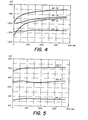
- the electrodes in the present example rapidly stabilized and had only a very slight drift, below 0.1 mV/min.
- the comparison electrodes on the other hand, had an uncontrollable drift (more than 1 mV/min) which was difficult or impossible to stabilize (see Fig. 3).
- the results obtained from test solutions of KC1 having a concentration of 10-2 to 10-5 M are shown in the following table. These results relate to electrodes previously rinsed in distilled water and then with the solution to be-measured at each change of concentration.
- F ig7 4 is a graph showing the variation in potential of virgin electrodes (including AK-14 to 16 samples for comparison), in dependence on the stabilization time.
- Electrode with reference cell comprising Prussian blue
- a sheet of Fe, Ag, Ni, Pt or porous conductive carbon about 0.05 to 0.2 mm thick was selected and immersed for a few minutes in a hot non-ionic detergent, then rinsed-a number of times in hot distilled water. After a further rinse in twice-distilled water, the sheet was dried for at least 4 hours at 150°C.
- the conductive sheet was handled with very great care in order to avoid depositing impurities (metal forceps were used), since Prussian blue is extremely sensitive to impurities.
- One of the conductive sheets was cathodized at lm A/ cm 2 in 1 N HC1 at 40°C.
- a Fe or Ni sheet requires 5 minutes treatment whereas Pt takes about 60 minutes; a conductive carbon sheet does not require cathodization.
- deposition of Prussian blue can be accelerated by inserting a second sheet (of platinum) into the mixture and applying a potential between the sheets, the first being negatively polarized so as to obtain a current density of 50 uA/cm 2 .
- This technique results in more uniform, homogeneous deposition than purely chemical methods.
- a suitably thick deposit is obtained by passing about 10-15 mCoulombs/cm electrode.
- the sheet portion (except for the contact zone 4b) was then covered with a sheet of PVC (mask) formed (see Fig. 1) with an aperture or window 4a about 3 to 5 mm in diameter, giving access to a corresponding area of active electrode.
- a self-adhesive sheet about 0.1 mm thick was used for mask 4.
- an ISM solution was poured into window 4 through a pipette.
- the solution was prepared from 6.6 mg of valinomycin (Val); 2.013 mg of bis (2-ethylhexyl)adipate; 2.044 g of high molecular weight-PVC and 20 ml of tetrahydrofuran (THF).
- THF tetrahydrofuran
- the solution was then evaporated, during which time the THF dissolved part of the PVC forming the peripheral walls of the window, so that the PVC binder penetrated into the walls of the mask and the ISM diaphragm. After drying, therefore, the diaphragm was intimately bonded to the walls of the mask by a compeletly sealing-tight junction zone.
- the resulting electrodes were used as follows (see Fig. 2). Using a micropipette, a drop (20 - 50 ul) of standard solution (or solution to be measured) was deposited in compartment 4a in contact with the ISM diaphragm 6.
- Connector 5 was connected to the terminals of a high-impedance electrometer (differential preamplifier, input greater than 10-3 ohms, current approx. 2 pA,then digital KEITHLEY-197 multimeter) and the external reference electrode, which comprised a sintered-tip micropipette in contact with the drop to be measured, containing a reference KC1 M solution and a plate of Ag/AgCl.
- the potential was measured every 6 seconds for a total of 6 minutes.
- the electrodes in the present example stabilized quickly and their drift was very small - below 0.1 mV/min.
- the results obtained on test solutions of KC1 at concentrations from 10 -2 to 10 5 M are shown in the following Table. These results relate to electrodes which have previously been rinsed in distilled water and then with the solution to be measured, at each change in concentration.
Abstract
Description
- The invention relates to the manufacture of laminar electrodes comprising a selectively ion-permeable diaphragm and used for determining specific ions in aqueous solution, e.g. Na , K+, Mg ,Ca , Cl , etc., inter alia in biological fluids.
- There are already a large number of prior-art electrodes and similar devices for selectively determining ions in aqueous solutions. The electrodes usually comprise an internal electrochemical reference half-cell at a stable potential and adapted, in conjunction with an external reference electrode immersed simultaneously with the measuring electrode in a solution to be analyzed, to form an electrochemical cell of a potential dependent on the presence of a given ion in the solution. In some texts, an assembly of this kind comprising two electrodes and a connecting electrolyte is described as a "battery". We shall avoid using this term here, since a "battery" produces current in contrast to the present cell, which delivers a potential only in order to avoid irreversibility conditions.
- The potential is proportional to the logarithm of the activity of the chosen ion in accordance with NERNST's well known equation E = E ± KlnCi where E is the standard potential and K is a constant. The potential is therefore proportional to the concentration of the ion, which can then be deduced by comparison with standard solutions.
- For example, documents CH-A-604 167 and US-A-4 214 968; 4 053 381; 4 171 246 (EASTMAN KODAK) describe electrodes in the form of dry multi-laminates comprising, in the following order, an insulating support, a metal electrically conductive layer covered with an insoluble salt of the metal, a part of the layer being used as a terminal for connection to an electrometer, a reference electrolyte and an ion-selective diaphragm for selectively measuring a given ion. The assembly made up of the metal layer, the insoluble salt and the reference electrolyte constitutes the internal reference half-cell at stable potential. Alternatively the assembly can be replaced by a conductive layer covered with a redox system, e.g. the quinone-hydroquinone couple, which system likewise comprises an internal reference cell at stable potential.
- The ionically selective diaphragm usually comprises a plasticizer and a hydrophobic matrix containing in dispersion an ionophoric substance, i.e. one of use for selectively detecting a given ion to the exclusion of any other ions in the solution to be analyzed, compare W. E. MORF et al., Ion-Selective Electrodes in Analytical Chemistry, Vol.I, FRIESER Editor, Plenum Press (1981), pp 221 ff.
- Document US-A-3 856 649 (MILES) describes an electrode having a similar structure except that the conductive element is filiform instead of laminar and the electrolyte layer is appreciably hydrated.
- Docunent GB-A-2 106 253 (FUJI) likewise describes an electrode for selectively deternining ions, the electrode being a laminate comprising an insulating support, a conductive layer covered with an insoluble salt of the metal forming the conductive layer, and a hydrophobic layer of an ion-selective nateriai (ISM) covering the rest. This document also describes a simplified variant electrode omitting not only the reference electrolyte but also the insoluble salt. In this varianL the electrode comprises only the conductive layer covered with ISM material (see also Anal. Chem. 44 (1972), 856).
- Document US-A-4 454 007 (DUPONT) likewise describes a laminar ion-selective electrode having the following structure: a baseplate of insulating material, a layer of conductive material, a layer comprising powdered carbon dispersed in a dielectric polymer, and finally an ion-selective diaphragm made of material which penetrates with the material in the preceding layer at their junction plane.
- In conventional practice, the previously-described electrodes are used as follows. When testing a solution for analysis, a drop thereof is deposited on to the diaphragm, which has selective ion permeability, and the drop is also placed in contact with the external reference electrode, e.g. via a salt bridge, the terminals of the ion-selective electrode and the reference electrode being connected to a suitable electrometer for reading the potential. In numerous prior-art cases, the external reference electrode may be similar to or identical with the measuring electrode, and the external reference potential can be supplied either by a standard solution deposited simultaneously with the solution to be analyzed (in which case the solutions make contact by diffusion into a porous element situated between the deposition areas) or by a fixed reference element (the salt bridge for example) forming part of the external reference electrode.
- In order to locate and fix the position of the drop of solution to be analyzed (and also the drop of standard solution when necessary) the ISM diaphragm is usually covered with a layer of insulating, waterproof material formed with compartments or windows giving access to only that portion of the ISM layer facing the window. This system prevents the drop spreading on the surface of the ISM layer and can also be used for selecting a fixed preset quantity of liquid for measuring, since the capacity of the compartments is kept constant from one electrode to the other.
- Electrodes of this kind, however, are capable of producing short-circuits as a result either of inter-layer diffusion of aqueous liquids or if the liquids accidentally come into contact with the edges of the electrodes. Attempts have been made to obviate these defects by various means, e.g. by tightly sealing the edges of the electrodes (GB-A-2 106 253) or by grooving the conductive layer so as to divide it into zones and filling the grooves with ISM material (GB-A-2 121 183). According to the invention, as summarised in claim 1, the risk of short-circuits has been obviated by completely tightly sealing the ion selective (ISM) diaphragm to the impermeable hydrophobic mask covering the electrode. The tight seal between these components completely prevents any inter-layer diffusion of aqueous liquids and eliminates the risk of short-circuits.
- The invention will now be described in greater detail with reference to the accompanying drawings in which:
- Fig. 1 is a diagrammatic section through an embodiment of the electrode constructed according to the invention;
- Fig. 2 is a diagram of a variant thereof;
- Fig. 3 is a larger-scale diagrammatic representation of a method of measurement using an external reference electrode;
- Fig. 4 is a graph showing the variation in potential of virgin electrodes with time, and
- Fig. 5 is a graph similar to Fig. 4 corresponding to other kinds of electrodes.
- Fig. 1 shows an electrode comprising the following components in succession; an insulating base plate or sheet 1, an electrically
conductive layer 2 co-operating with thenext layer 3 to form a redox system, an internal electrochemical reference cell at stable potential, and finally amask 4 covering the rest and made of hydrophobic insulating material and formed with twowindows 4a and 4b.Window 4b is for establishing electric contact (e.g. via a conductor 5) and thus provides a contact terminal connecting theconductive layer 2 to one terminal of an electrometer (not shown). - The electrode also comprises a
diaphragm 6 disposed in window 4a and in contact withreference element 3.Diaphragm 6 selects specific ions, e.g. K+ ions, and is secured in completely sealing-tight manner to the walls of the mask as a result of inter-diffusion of the (polymer) binder ofdiaphragm 6 and the material ofmask 4. This interpenetration results from the method of manufacture as defined in claim 1 and as will be detailed later. - The configuration of the variant in Fig. 2 is similar to Fig. 1, and consequently like elements are denoted by like reference numbers. This variant, however, differs with regard to the nature of the reference half-cell at stable potential. In the present case, in addition to the conductive metal base, the cell comprises a
layer 7 of an insoluble salt of the conductive-base metal and a reference electrolyte where the anion is identical with that of the insoluble salt and the cation identical with that which is to be measured in the analyzed substance. In order for example to determine K+, theconductive base 2 can be silver, the insoluble salt can be a silver halide such as AgCl, and theelectrolyte 8 can be a potassium halide, e.g. KC1. - Fig. 3 illustrates a method of analyzing a
solution 10 using the electrode in Fig. 2 (the first variant will of course be the same in operation). - To make the analysis, a
drop 10 of the solution for analysis is taken and deposited in the compartment 4a formed inmask 4, so that it makes contact with the ion-selective diaphragm 6. Next, contact is made with an electrometer via a coupling means, e.g. a pipette 11 having aporous glass tip 12 and a reference electrode 13 (e.g. a silver plate covered with AgCl and immersed in a reference electrode 14, e.g. KC1 N). Contact with the electrometer is made viaconductor 5 and also via aconductor 15 connected to thereference electrode 13. Next, the potential of the electrochemical cell formed by the aforementioned elements - is measured and, if the internal reference potential (elements reference solution 14 are known, it is possible to calculate the concentration of chosen ions insolution 10 by using the NERNST relation (see e.g. "Physical Chemistry" by W. J. Moore, Prentice-Hall, Inc. 3e ed. London 1962, p.389). - The electrodes according to the invention can be constructed by using an insulating base 1 comprising a shee;, film or plate of a polymer such as PVC, mylar, cellulose acetate, polycarbonates, plexiglass, polystyrene, etc. The nature of the insulating base is not critical provided it does not interfere with the other electrode components, and it can be made from conventional materials and by conventional methods.
- The
conductive layer 2 can be made from a metal sheet or film, e.g. Fe, Pt, Ag, Cu, Ni, Co, etc., inter alia if the layer is coated with aninsoluble salt 7 of the base metal. If forexample layer 2 is silver, it can comprise a sheet of silver between 10 and 100 µm thick or a silver deposit produced by "electroless" techniques or by vaporization in vacuo or by using a silver paint, e.g. Type P-720 or P-750 produced by JOHNSON-MATTHEY, England. An aforementioned silver layer can be coated with an insoluble silver salt, e.g. silver chloride, by oxidation by conventional methods, e.g. chemically or by anodization in the presence of HC1 and by conventional methods. - In the case of the electrode shown in Fig. 1, the internal reference-potential element is a redox couple, in which case the conductive layer, in addition to a metal as previously described, can comprise other conductive substances such as carbon powder or fibres (in a polymer) or a porous carbon sheet.
- The redox reference system, with or without polymer binders, can be a conventional redox system such as quin- hydrone or ferrous/ferric couples such as Fe(CN)6 -4/ Fe(CN)6 3 or cobaltous/cobaltic. e.g.
- Co(terpyridyl)2 +3/Co(terpyridyl)2 +2.
- It is also (unexpectedly) possible to use Prussian blue. In that case, the system is prepared by immersing the conductive layer in an FeCl3 solution and subsequently in an alkaline ferrocyanide solution. The result is an adhesive layer of Prussian blue between 0.1 and 10 µm thick and having a potential (on an Fe, Ni, Co or carbon support) which is particularly stable. The following are examples of binders suitable for redox couples: gelatine, polyvinyl alcohol, polyacrylamide, polyvinyl pyrrolidone, etc.
- When using a
conductive metal layer 2 covered by an insoluble salt 7 (the variant in Fig. 2) it is advantageous to coat it with an electrolyte such as KC1 dispersed in a hydrophilic polymer such as gelatine or polyhydroxyacrylic acid. Alternatively (and this is an unexpected technique) use can be made of a layer of electrolyte which is completely dry and without a hydrophilic binder, e.g. KCl, NaCl or another alkali-metal or alkaline earth salt, etc., obtained by complete evaporation and drying of a solution of one of these salts. The possibility of using a dehydrated alkaline salt as the stable-potential reference electrolyte is a surprising and unexpected development, since the resulting electrode rapidly stabilizes and has a very short response time. - The
mask 4 covering the electrode can be made of a hydrophobic polymer such as PVC, polyacrylate, polystyrene, polycarbonate, etc. The mask does not require any complicated device for positioning it, since the sealing-tightness of the operating zone of the electrode does not depend on the actual mask over the other components of the laminate, but rather on the uniformity of the material joining themask 4 to the ion-selective diaphragm 6. For example the mask can be a single sheet of adhesive polymer applied by hot or cold pressure on to the other components of the laminate and intimately following their shape. Alternatively, the "solvent casting" technique can be used. -
Diaphragm 6 comprises a binder, a plasticizer and an ionophore. The choice of ionophore will depend on the nature of the ions to be deternined, e.g. valinomycin for potassium, methyl-monensin for sodium, certain phosphonic esters for calcium, etc. Detailed information on the required ionophores, depending on the chosen type of analysis, will be found amomg the previous citations, inter alia document US-A-4 454 007. - The binder for the ionophoric compound can be a polymer such as polyvinyl chloride (PVC), polystyrene, polyacrylates, polycarbonates, polyesters (polyethylene terephthalate), etc. Preferably, to obtain optimum compatibility between
member 6 and mask 4 (i.e. to ensure maximum sealing-tightness between these components) the polymer chosen for the binder ofdiaphragm 6 will be identical with the material in the mask, e.g. PVC. Also, in order to assemble the diaphragm, a solution of constituents thereof should be applied in a solvent in which the mask material is also soluble. - The plasticizer used in the diaphragm can be one of the conventional plasticizers such as dimethylphthalate, dioctylphenylphosphonate, dibutylphtalate, tritolylphosphate, dibutylsebacate, etc. Other examples of plasticizers will be found in the citations referred to.
- The practical construction of the electrodes by the method according to the invention is sinple and follows substantially from the preceding considerations.
- The various laminate components are selected and superposed and joined either by simple adhesion or by pressing when cold or hot. For example, in one embodiment of an electrode as per Fig. 1, the method is as follows:
- A layer or e.g. sheet of silver is deposited on to a plate or sheet of plastics and is anodized in a hydrochloric medium to form an AgCl layer between a few nm and a few µm thick (e.g. 10 nm to 100 µm).
- Next, an aqueous solution of KC1 at a concentration between e.g. 0.01 M and 3.5 M is deposited on the AgCl layer and the layer is evaporated and dehydrated until completely dry. The assembly is then covered with an adhesive PVC mask which has previously been formed with an opening corresponding to window 4a.
- The thickness of the mask is of the order of 0.05 to 0.5 mm. Next, a solution of ionophore containing PVC binder, a plasticizer and a solvent such as THF is deposited in the opening in the mask. The solution is then dried to for a film constituting the
diaphragm 6. During this operation, the solvent dissolves part of the walls of the mask with which it is in contact and, after evaporation, forms a completely tight seal between the diaphragm and the walls of opening 4a. - The invention is illustrated by the following examples.
- Electrode with reference cell comprising a dry electrolyte
- A silver sheet 0.1 mm thick was selected and polished, degreased, cleaned and rinsed by conventional methods (emery No. 600, isopropyl alcohol, distilled water, conc. NH40H followed by distilled water). One surface of it was then protected by applying a self-adhesive polyethylene film from 0.2 to 0.5 mm thick. Polyethylene may be replaced by an adhesive PVC or mylar sheet.
- An electric contact was formed at the free end of the sheet, after which it was immersed in an electrolytic bath of 0.5 M aqueous sulphuric acid and the silver sheet was cathodized under normal conditions: platinum or vitreous carbon counter-electrode, ambient temperature, voltage 4.5 V, duration of treatment 20 min.
- The sheet was rinsed with twice-distilled water and placed in a second electrolytic bath of 0.1 N aqueous hydrochloric acid and anodized under the following conditions: ambient temperature, current density 0.3 A/dm2,
duration 7 minutes. (This and the subsequent operations must be carried out under subdued light to avoid damaging the photosensitive silver chloride). - The sheet was again rinsed and depolarized in the following manner: Two sheets anodized as described were placed in a vessel containing twice-distilled hot water (60 - 80°C) and were elelectrically short-circuited for 12 hours. After this treatment, the sheets comprised a layer of silver protectedon one surface by the plastics sheet and covered on the other surface by a thickness of about 1 to 15 µm of AgCl. Manufacture of these reference components was checked by means of a sample, the potential of which was measured in a standard 3 M KC1 solution using a standard calomel reference counter-electrode. The measured value (-33 to -34 mV under normal conditions) was correct to within 0.1 mV of the theoretical value. The sheets were dried and kept in darkness until used for manufacturing the electrodes. Note that the anodization treatment can be replaced by oxidation for 1 to 2 minutes at ambient temperature in a solution containing 10.01 g potassium bichromate, 15.4 g KC1 and 25 ml of conc. HC1 per litre.
- A 7 x 15 mm portion was cut from a sheet of Ag/AgCl prepared as described hereinbefore, and about 20 µl of a 3.5 M aqueous solution of KC1 was deposited over the entire non-protected surface, using a pipette. The water was evaporated from the solution and the plate portion was dried for 8 - 12 hours at 110° until completely dehydrated. After this period the activated surface was covered with fine KCl crystals (about 5 mg) uniformly distributed over the entire surface. In this treatment, the KC1 was not associated with any hydrophilic matrix as in the prior art. Dry KCl layers were also prepared by the same method but using aqueous solutions containing 7 x 10⁻³ M and 0.1 M KC1. The physical vapour deposition method was also used.
- An area of a few mm2 was cleared near the end of the plate portion to serve as a place of electric contact, and a connector (e.g. a connecting wire) was soldered thereto, after which the plate portion was covered with a PVC sheet (mask) formed (see Fig. 2) with an opening or window 4a about 3 to 5 mm in diameter giving access to a corresponding - area of the active layer of the electrode.
Mask 4 was made from a self-adhesive sheet about 0.1 mm thick. - About 20 ul of an ISM solution prepared from 6.6 mg of valinomycin (Val); 2.014 mg of bis(2-ethylhexyl)adipate: 2.044 g of high molecular-weight PVC and
- 20 ml of tetrahydrofuran (THF) was then poured into
window 4 through a pipette. The solution was then evaporated, during which time the THF dissolved part of the PVC forming the peripheral walls of the window, resulting in penetration of the PVC binder into the walls of the mask and the ISM membrane. After drying, therefore, the membrane was intimately bonded to the mask walls by a completely water-tight junction zone. - The resulting electrodes were used as follows (see Fig. 3). Using a micropipette, a drop (20 - 50 µl) of standard solution (or of solution to be measured) was placed in the compartment 4a in contact with the
ISM diaphragm 6.Connector 5 was connected to the terminals of a high-impedance electrometer (differential preamplifier, input impedance more than 10-13 ohms, current approximately 2 pA, followed by Digital KEITHLEY-197 multimeter) and also to the external reference electrode, which comprised a sintered-tip micropipette in contact with the drop to be measured and containing a KC1 reference solution and a plate of Ag/AgCl. - A comparative test was also made on conventionally constructed electrodes without a dry KC1 electrolyte. In the test, the potential was maasured every 6 seconds for a total period of 6 minutes. The electrodes in the present example rapidly stabilized and had only a very slight drift, below 0.1 mV/min. The comparison electrodes, on the other hand, had an uncontrollable drift (more than 1 mV/min) which was difficult or impossible to stabilize (see Fig. 3). The results obtained from test solutions of KC1 having a concentration of 10-2 to 10-5 M are shown in the following table. These results relate to electrodes previously rinsed in distilled water and then with the solution to be-measured at each change of concentration.

- Fig7 4 is a graph showing the variation in potential of virgin electrodes (including AK-14 to 16 samples for comparison), in dependence on the stabilization time.
- A sheet of Fe, Ag, Ni, Pt or porous conductive carbon about 0.05 to 0.2 mm thick was selected and immersed for a few minutes in a hot non-ionic detergent, then rinsed-a number of times in hot distilled water. After a further rinse in twice-distilled water, the sheet was dried for at least 4 hours at 150°C. The conductive sheet was handled with very great care in order to avoid depositing impurities (metal forceps were used), since Prussian blue is extremely sensitive to impurities.
- A solution of 20 mM of K4Fe(CN)6, analytical grade, was also prepared after being twice recrystallized from thrice-distilled water, which was acidified to 0.01 M with HC1. The same method was used with Fed to prepare a corresponding solution of FeCl3 at 0.01 M of HC1.
- When the two solutions were carefully mixed, the mixture remained in unstable equilibrium; Prussian blue was precipitated subsequently.
- One of the conductive sheets was cathodized at lmA/cm2 in 1 N HC1 at 40°C. A Fe or Ni sheet requires 5 minutes treatment whereas Pt takes about 60 minutes; a conductive carbon sheet does not require cathodization.
- After this treatment, a sheet was slowly immersed in a freshly prepared mixture of iron chloride solution and ferrocyanide solution, except for a small portion for subsequently forming an electric connection. After five minutes, a layer of Prussian blue formed on the conductive sheet and continued to thicken if the treatment was prolonged. Depending on the desired thickness, the sheet was taken out of the bath after 5 to 20 minutes, carefully rinsed with thrice-distilled water and dried in a desiccator on P 2 0 5.
- Alternatively, deposition of Prussian blue can be accelerated by inserting a second sheet (of platinum) into the mixture and applying a potential between the sheets, the first being negatively polarized so as to obtain a current density of 50 uA/cm2. This technique results in more uniform, homogeneous deposition than purely chemical methods. A suitably thick deposit is obtained by passing about 10-15 mCoulombs/cm electrode.
- After the sheet had thus been covered with Prussian blue, one surface of it was coated with a self-adhesive protective film of polyethylene, PVC or mylar between 0.1 and 0.5 mm thick, after which a portion measuring approximately 7 x 15 mm was cut out of the sheet. The portion was given an end zone which was not coated with the redox system, and of use for subsequently connecting the electrode to an electrometer.
- The sheet portion (except for the
contact zone 4b) was then covered with a sheet of PVC (mask) formed (see Fig. 1) with an aperture or window 4a about 3 to 5 mm in diameter, giving access to a corresponding area of active electrode. A self-adhesive sheet about 0.1 mm thick was used formask 4. - Next, about 20 µl of an ISM solution was poured into
window 4 through a pipette. The solution was prepared from 6.6 mg of valinomycin (Val); 2.013 mg of bis (2-ethylhexyl)adipate; 2.044 g of high molecular weight-PVC and 20 ml of tetrahydrofuran (THF). The solution was then evaporated, during which time the THF dissolved part of the PVC forming the peripheral walls of the window, so that the PVC binder penetrated into the walls of the mask and the ISM diaphragm. After drying, therefore, the diaphragm was intimately bonded to the walls of the mask by a compeletly sealing-tight junction zone. - The resulting electrodes were used as follows (see Fig. 2). Using a micropipette, a drop (20 - 50 ul) of standard solution (or solution to be measured) was deposited in compartment 4a in contact with the
ISM diaphragm 6. -
Connector 5 was connected to the terminals of a high-impedance electrometer (differential preamplifier, input greater than 10-3 ohms, current approx. 2 pA,then digital KEITHLEY-197 multimeter) and the external reference electrode, which comprised a sintered-tip micropipette in contact with the drop to be measured, containing a reference KC1 M solution and a plate of Ag/AgCl. In the test, the potential was measured every 6 seconds for a total of 6 minutes. The electrodes in the present example stabilized quickly and their drift was very small - below 0.1 mV/min. The results obtained on test solutions of KC1 at concentrations from 10-2 to 105 M are shown in the following Table. These results relate to electrodes which have previously been rinsed in distilled water and then with the solution to be measured, at each change in concentration. -

- The stability of the electrodes was very satisfactory; after being stabilized, the potential drift did not exceed + 0.2 mV/min. Stabilization took about 2 minutes (see Fig. 5).
Claims (6)
Applications Claiming Priority (2)
| Application Number | Priority Date | Filing Date | Title |
|---|---|---|---|
| CH550385 | 1985-12-23 | ||
| CH5503/85 | 1985-12-23 |
Publications (2)
| Publication Number | Publication Date |
|---|---|
| EP0230572A1 true EP0230572A1 (en) | 1987-08-05 |
| EP0230572B1 EP0230572B1 (en) | 1990-07-04 |
Family
ID=4294708
Family Applications (1)
| Application Number | Title | Priority Date | Filing Date |
|---|---|---|---|
| EP86116841A Expired - Lifetime EP0230572B1 (en) | 1985-12-23 | 1986-12-03 | A method of manufacturing ion-selective electrodes for analyzing selected ions in solution |
Country Status (4)
| Country | Link |
|---|---|
| US (1) | US4867860A (en) |
| EP (1) | EP0230572B1 (en) |
| JP (1) | JPH0750059B2 (en) |
| DE (1) | DE3672473D1 (en) |
Cited By (1)
| Publication number | Priority date | Publication date | Assignee | Title |
|---|---|---|---|---|
| EP0282651A2 (en) * | 1987-03-16 | 1988-09-21 | Horiba, Ltd. | Sheet type ion measurement electrode |
Families Citing this family (8)
| Publication number | Priority date | Publication date | Assignee | Title |
|---|---|---|---|---|
| US5003820A (en) * | 1990-05-24 | 1991-04-02 | Eric Dittbrenner | Electronic speedometer for snow skis |
| KR940004667B1 (en) * | 1990-07-27 | 1994-05-27 | 한국과학기술연구원 | Moisture sensor and manufacturing method thereof |
| EP0600607A3 (en) * | 1992-10-28 | 1996-07-03 | Nakano Vinegar Co Ltd | Coulometric analysis method and a device therefor. |
| FR2764385B1 (en) * | 1997-06-06 | 1999-07-16 | Commissariat Energie Atomique | MICROSYSTEM FOR ANALYZING LIQUIDS WITH INTEGRATED CUP |
| DE10108539B4 (en) * | 2001-02-22 | 2007-01-04 | Dpst Behnert Gmbh | Direct potentiometric pH sensor |
| DE102010062659A1 (en) * | 2010-12-08 | 2012-06-14 | Endress + Hauser Conducta Gesellschaft für Mess- und Regeltechnik mbH + Co. KG | Electrode e.g. reference electrode, for electrochemical measuring system in e.g. medicine, has potential forming element arranged in chamber, and conductor contacting forming element, deriving potential from chamber and formed from fiber |
| WO2020249225A1 (en) * | 2019-06-14 | 2020-12-17 | Robert Bosch Gmbh | Metal ferrocyanide-doped carbon as transducer for ion selective electrode |
| JP2023030993A (en) | 2021-08-24 | 2023-03-08 | Koa株式会社 | All-solid potassium ion selective electrode and method for manufacturing all-solid potassium ion selective electrode |
Citations (1)
| Publication number | Priority date | Publication date | Assignee | Title |
|---|---|---|---|---|
| US4454007A (en) * | 1983-01-27 | 1984-06-12 | E. I. Du Pont De Nemours And Company | Ion-selective layered sensor and methods of making and using the same |
Family Cites Families (38)
| Publication number | Priority date | Publication date | Assignee | Title |
|---|---|---|---|---|
| US27524A (en) * | 1860-03-20 | Sealing-lock eor railway-cars | ||
| US3485723A (en) * | 1965-10-22 | 1969-12-23 | Du Pont | Enzymatic determination of nitrogen-containing compounds and enzymes reactive therewith |
| FR1497240A (en) * | 1965-10-22 | 1967-10-06 | Du Pont | Method for determining the content of nitrogen compounds in various samples |
| USRE27524E (en) | 1965-10-22 | 1972-11-28 | Enzymatic determination of nitrogen- containing compounds and enzymes reactive therewith | |
| BE786291A (en) * | 1971-07-20 | 1973-01-15 | Technicon Instr | DIAGNOSTIC COMPOSITIONS FOR DETERMINATION OF GLUTAMATE-OXALATE-TRANSAMINASE (GOT) AND GLUTAMATE-PYRUVATE-TRANSAMINASE (GPT) |
| NL7113260A (en) * | 1971-09-27 | 1973-03-29 | Ion selective measuring electrode - for control of industrial processes etc | |
| US3856649A (en) * | 1973-03-16 | 1974-12-24 | Miles Lab | Solid state electrode |
| FR2352300A1 (en) * | 1976-05-19 | 1977-12-16 | Eastman Kodak Co | ELECTRODE FOR THE SELECTIVE TITRATION OF AN ION |
| US4053381A (en) * | 1976-05-19 | 1977-10-11 | Eastman Kodak Company | Device for determining ionic activity of components of liquid drops |
| US4171246A (en) * | 1976-05-19 | 1979-10-16 | Eastman Kodak Company | Method for determining ionic activity of components of liquid drops |
| US4133735A (en) * | 1977-09-27 | 1979-01-09 | The Board Of Regents Of The University Of Washington | Ion-sensitive electrode and processes for making the same |
| FR2418462A1 (en) * | 1978-02-22 | 1979-09-21 | Anvar | Enzymic determn. of glucose - by measurement of reaction rate in the presence of competitive inhibitor |
| US4214968A (en) * | 1978-04-05 | 1980-07-29 | Eastman Kodak Company | Ion-selective electrode |
| US4314895A (en) * | 1978-07-17 | 1982-02-09 | Nova Biomedical Corporation | Method of making liquid membrane electrode |
| US4257862A (en) * | 1978-07-24 | 1981-03-24 | Eastman Kodak Company | Chemical analyzer |
| US4184936A (en) * | 1978-07-24 | 1980-01-22 | Eastman Kodak Company | Device for determining ionic activity |
| JPS5564759U (en) * | 1978-10-27 | 1980-05-02 | ||
| US4199411A (en) * | 1978-10-31 | 1980-04-22 | Eastman Kodak Company | Halide ion-selective devices and methods of determining halides |
| US4199412A (en) * | 1978-10-31 | 1980-04-22 | Eastman Kodak Company | Halide ion-selective devices and method |
| JPS5823079B2 (en) * | 1978-11-15 | 1983-05-12 | バテル メモリアル インステイチユ−ト | Analytical methods and means for determining the amount of hydrogen peroxide in an aqueous medium and the amount of organic substrates that generate hydrogen peroxide by enzymatic oxidation |
| US4273639A (en) * | 1979-06-20 | 1981-06-16 | Eastman Kodak Company | Capillary bridge in apparatus for determining ionic activity |
| US4336091A (en) * | 1979-06-20 | 1982-06-22 | Eastman Kodak Company | Method of making capillary bridge in apparatus for determining ionic activity |
| CA1141637A (en) * | 1979-10-10 | 1983-02-22 | Erma C. Cameron | Cofactor indicator compositions |
| US4272328A (en) * | 1979-12-05 | 1981-06-09 | Eastman Kodak Company | Buffer overcoat for CO2 ion-selective electrodes |
| US4303408A (en) * | 1980-02-05 | 1981-12-01 | Eastman Kodak Company | Removal of interferents in analytical assays in a two phase interferent-removal zone |
| US4282079A (en) * | 1980-02-13 | 1981-08-04 | Eastman Kodak Company | Planar glass ion-selective electrode |
| DE3113777A1 (en) * | 1981-04-04 | 1982-10-28 | Basf Ag, 6700 Ludwigshafen | METHOD FOR PRODUCING FE (DOWN ARROW) 4 (DOWN ARROW) (FE (CN) (DOWN ARROW) 6 (DOWN ARROW)) (DOWN ARROW) 3 (DOWN ARROW) PIGMENTS, AND THE PIGMENTS OBTAINED AFTER THE PROCESS |
| AU8309682A (en) * | 1981-05-26 | 1982-12-02 | Daini Seikosha K.K. | Electrochromic display device |
| DE3222464A1 (en) * | 1981-06-15 | 1982-12-30 | Fuji Photo Film Co., Ltd., Minami-Ashigara, Kanagawa | ELECTRODE FOR DETERMINING THE HALOGENION CONCENTRATION AND PERMANENT PLASTICS FOR THEIR PRODUCTION |
| JPS5810645A (en) * | 1981-07-13 | 1983-01-21 | Fuji Photo Film Co Ltd | Film-shaped ion selection electrode and ion concentration measuring device using the same |
| JPS5814050A (en) * | 1981-07-17 | 1983-01-26 | Fuji Photo Film Co Ltd | Ion activity measuring apparatus |
| EP0085276A1 (en) * | 1981-12-10 | 1983-08-10 | Greiner Electronics Ag | Method for the immuno-chemical detection of substances |
| JPS58120222A (en) * | 1982-01-12 | 1983-07-18 | Seiko Instr & Electronics Ltd | Functional electrode |
| DE3206663A1 (en) * | 1982-02-25 | 1983-09-01 | Basf Ag, 6700 Ludwigshafen | METHOD FOR PRODUCING BLUE IRON HEXACYANOFERRATE III PIGMENTS |
| JPS58156848A (en) * | 1982-03-15 | 1983-09-17 | Fuji Photo Film Co Ltd | Ion selective electrode and its manufacture |
| JPS58186039A (en) * | 1982-04-23 | 1983-10-29 | Fuji Photo Film Co Ltd | Measuring apparatus of ion activity |
| US4416735A (en) * | 1982-06-17 | 1983-11-22 | Eastman Kodak Company | Diluent and method for potentiometric assay of liquids |
| JPS594659A (en) * | 1982-06-30 | 1984-01-11 | Shin Etsu Chem Co Ltd | Silicone coating agent |
-
1986
- 1986-12-03 DE DE8686116841T patent/DE3672473D1/en not_active Expired - Lifetime
- 1986-12-03 EP EP86116841A patent/EP0230572B1/en not_active Expired - Lifetime
- 1986-12-16 US US06/942,305 patent/US4867860A/en not_active Expired - Fee Related
- 1986-12-22 JP JP61306176A patent/JPH0750059B2/en not_active Expired - Lifetime
Patent Citations (1)
| Publication number | Priority date | Publication date | Assignee | Title |
|---|---|---|---|---|
| US4454007A (en) * | 1983-01-27 | 1984-06-12 | E. I. Du Pont De Nemours And Company | Ion-selective layered sensor and methods of making and using the same |
Cited By (2)
| Publication number | Priority date | Publication date | Assignee | Title |
|---|---|---|---|---|
| EP0282651A2 (en) * | 1987-03-16 | 1988-09-21 | Horiba, Ltd. | Sheet type ion measurement electrode |
| EP0282651A3 (en) * | 1987-03-16 | 1990-01-10 | Horiba, Ltd. | Sheet type ion measurement electrode |
Also Published As
| Publication number | Publication date |
|---|---|
| JPS62157564A (en) | 1987-07-13 |
| US4867860A (en) | 1989-09-19 |
| JPH0750059B2 (en) | 1995-05-31 |
| DE3672473D1 (en) | 1990-08-09 |
| EP0230572B1 (en) | 1990-07-04 |
Similar Documents
| Publication | Publication Date | Title |
|---|---|---|
| US4214968A (en) | Ion-selective electrode | |
| US5397451A (en) | Current-detecting type dry-operative ion-selective electrode | |
| Arnold et al. | Ion-selective electrodes | |
| US4528085A (en) | Ion selective electrode and process of preparing the same | |
| US4171246A (en) | Method for determining ionic activity of components of liquid drops | |
| EP0079502A1 (en) | Multilayer enzyme electrode membrane, method of making same and polarographic cell structure | |
| EP0024191A2 (en) | Reference elements, ion-selective electrodes containing said elements and method of preparing said elements | |
| JPS62116252A (en) | Method and device for electrochemical analysis | |
| EP0512070A1 (en) | Multi-analyte sensing electrolytic cell | |
| EP0325562A2 (en) | Dry ion-selective electrodes for the determination of ionic species in aqueous media | |
| GB1584788A (en) | Ion-selective electrode | |
| JPH03503677A (en) | reference electrode | |
| US4683048A (en) | Method of manufacturing ion selective electrode pair | |
| US5415746A (en) | Potentiometric ion determinations using enhanced selectivity asymmetric ion-selective membrane | |
| US5840168A (en) | Solid contact ion-selective electrode | |
| EP0230572B1 (en) | A method of manufacturing ion-selective electrodes for analyzing selected ions in solution | |
| US4199412A (en) | Halide ion-selective devices and method | |
| US4859306A (en) | Selectively ion-permeable dry electrodes for analyzing selected ions in aqueous solution | |
| JP2001500259A (en) | Analysis cell | |
| US4259164A (en) | Silver/silver halide electrodes comprising chromium or nickel | |
| EP0230573B1 (en) | Selectively ion-permeable dry electrodes for analyzing selected ions in aqueous solution | |
| US7083709B2 (en) | Potentiometric, ion-selective electrode | |
| EP0215446A2 (en) | Device and method for measuring ion activity | |
| Miyahara et al. | Shift and drift of electromotive forces of solid-state electrodes with ion-selective liquid membranes | |
| US3655526A (en) | Potentiometric titration process |
Legal Events
| Date | Code | Title | Description |
|---|---|---|---|
| PUAI | Public reference made under article 153(3) epc to a published international application that has entered the european phase |
Free format text: ORIGINAL CODE: 0009012 |
|
| 17P | Request for examination filed |
Effective date: 19861203 |
|
| AK | Designated contracting states |
Kind code of ref document: A1 Designated state(s): CH DE FR GB IT LI |
|
| RAP1 | Party data changed (applicant data changed or rights of an application transferred) |
Owner name: F. HOFFMANN-LA ROCHE AG |
|
| 17Q | First examination report despatched |
Effective date: 19891011 |
|
| GRAA | (expected) grant |
Free format text: ORIGINAL CODE: 0009210 |
|
| AK | Designated contracting states |
Kind code of ref document: B1 Designated state(s): CH DE FR GB IT LI |
|
| ITF | It: translation for a ep patent filed |
Owner name: BARZANO' E ZANARDO MILANO S.P.A. |
|
| REF | Corresponds to: |
Ref document number: 3672473 Country of ref document: DE Date of ref document: 19900809 |
|
| ET | Fr: translation filed | ||
| PLBE | No opposition filed within time limit |
Free format text: ORIGINAL CODE: 0009261 |
|
| STAA | Information on the status of an ep patent application or granted ep patent |
Free format text: STATUS: NO OPPOSITION FILED WITHIN TIME LIMIT |
|
| 26N | No opposition filed | ||
| ITTA | It: last paid annual fee | ||
| PGFP | Annual fee paid to national office [announced via postgrant information from national office to epo] |
Ref country code: FR Payment date: 19931109 Year of fee payment: 8 |
|
| PGFP | Annual fee paid to national office [announced via postgrant information from national office to epo] |
Ref country code: CH Payment date: 19931112 Year of fee payment: 8 |
|
| PGFP | Annual fee paid to national office [announced via postgrant information from national office to epo] |
Ref country code: DE Payment date: 19931124 Year of fee payment: 8 |
|
| PGFP | Annual fee paid to national office [announced via postgrant information from national office to epo] |
Ref country code: GB Payment date: 19931129 Year of fee payment: 8 |
|
| PG25 | Lapsed in a contracting state [announced via postgrant information from national office to epo] |
Ref country code: GB Effective date: 19941203 |
|
| PG25 | Lapsed in a contracting state [announced via postgrant information from national office to epo] |
Ref country code: LI Effective date: 19941231 Ref country code: CH Effective date: 19941231 |
|
| GBPC | Gb: european patent ceased through non-payment of renewal fee |
Effective date: 19941203 |
|
| PG25 | Lapsed in a contracting state [announced via postgrant information from national office to epo] |
Ref country code: FR Effective date: 19950831 |
|
| REG | Reference to a national code |
Ref country code: CH Ref legal event code: PL |
|
| PG25 | Lapsed in a contracting state [announced via postgrant information from national office to epo] |
Ref country code: DE Effective date: 19950901 |
|
| REG | Reference to a national code |
Ref country code: FR Ref legal event code: ST |
|
| PG25 | Lapsed in a contracting state [announced via postgrant information from national office to epo] |
Ref country code: IT Free format text: LAPSE BECAUSE OF NON-PAYMENT OF DUE FEES;WARNING: LAPSES OF ITALIAN PATENTS WITH EFFECTIVE DATE BEFORE 2007 MAY HAVE OCCURRED AT ANY TIME BEFORE 2007. THE CORRECT EFFECTIVE DATE MAY BE DIFFERENT FROM THE ONE RECORDED. Effective date: 20051203 |