EP0229876A2 - On-vehicle head up display device - Google Patents
On-vehicle head up display device Download PDFInfo
- Publication number
- EP0229876A2 EP0229876A2 EP86112835A EP86112835A EP0229876A2 EP 0229876 A2 EP0229876 A2 EP 0229876A2 EP 86112835 A EP86112835 A EP 86112835A EP 86112835 A EP86112835 A EP 86112835A EP 0229876 A2 EP0229876 A2 EP 0229876A2
- Authority
- EP
- European Patent Office
- Prior art keywords
- windshield glass
- optical system
- display
- image
- virtual image
- Prior art date
- Legal status (The legal status is an assumption and is not a legal conclusion. Google has not performed a legal analysis and makes no representation as to the accuracy of the status listed.)
- Granted
Links
Images


Classifications
-
- G—PHYSICS
- G02—OPTICS
- G02B—OPTICAL ELEMENTS, SYSTEMS OR APPARATUS
- G02B27/00—Optical systems or apparatus not provided for by any of the groups G02B1/00 - G02B26/00, G02B30/00
- G02B27/01—Head-up displays
- G02B27/0101—Head-up displays characterised by optical features
-
- G—PHYSICS
- G02—OPTICS
- G02B—OPTICAL ELEMENTS, SYSTEMS OR APPARATUS
- G02B27/00—Optical systems or apparatus not provided for by any of the groups G02B1/00 - G02B26/00, G02B30/00
- G02B27/01—Head-up displays
- G02B27/0101—Head-up displays characterised by optical features
- G02B2027/0118—Head-up displays characterised by optical features comprising devices for improving the contrast of the display / brillance control visibility
- G02B2027/012—Head-up displays characterised by optical features comprising devices for improving the contrast of the display / brillance control visibility comprising devices for attenuating parasitic image effects
Definitions
- the present invention relates to an on-vehicle head up display device, and more particularly to an on-vehicle head up display device utilizing a windshield glass of an automobile and indicating various information with use of a virtual image optical system.
- HUD on-vehicle head up display device
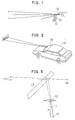
- Figs. I and 2 show a fundamental construction of the HUD in the prior art.
- the HUD is constituted of a display unit II installed at a center position of a dash board, for example, a (dioptric) optical system 12 such as a lens, and a catoptric system using a windshield glass 13.
- the display unit II employs LED, LCD and the like.
- a small image of the display unit 11 is enlarged by the optical system 12 and the virtual image optical system formed by the windshield glass 13, and is formed as a virtual image at a front position of the windshield glass 13.
- the virtual image (indication of speed, in this case) indicated by the display unit II of the HUD is perceived by a driver as if the display image were present at a fixed distance in front of an automobile 14.
- An image formation technique such that display information by LED or LCD and image information such as visible framework are formed in a fixed optical field is traditionally used in a camera finder, for example.
- a technique in the HUD is basically similar to such a display technique as mentioned above.
- the technique in the HUD includes some problems to be solved in such a point that the windshield glass is used as the catoptric system.
- One of the problems is caused by the use of the windshield glass as a half mirror having a relatively high transmittance.
- light beam directed from a point on the display unit 11 through the optical system 12 to the windshield glass 13 is reflected on two interfaces between air and glass on the outside and inside of the automobile.
- the optical system of the HUD is primarily provided on the dash board, it is necessary to set large an incident and reflective angle to the windshield glass. As a result, reflective images as reflected on the two reflective surfaces are slipped to generate perception of a double image.
- the light generated from a point on the display unit II is allowed to enter the windshield glass in the form of beam from an object point 17 on a virtual image formed by the optical system 12. Therefore, the beam is reflected on the two reflection interfaces of the windshield glass 13, and is allowed to enter driver's eyes 16 along two paths as shown by solid lines. This is caused by refraction at the interface between glass and air on the outside of the windshield glass. Owing to such a slip of the light path, the virtual image of the object point 17 is perceived double as shown by numerals 17", and accordingly, the driver cannot visibly perceive a clear display image.
- the windshield glass is treated by coating to form a mirror or half mirror having a high reflectance on an inner surface of the windshield glass.
- a lower area of the windshield glass plays an important role for the driver since he watches a fender part of the vehicle body so as to grasp a condition of the vehicle body. Therefore, if the visibility of the lower area of the windshield glass is hindered, the drivability is very reduced.
- poor visibility of the windshield glass causes hindrance in quick perception of any obstacle existing in front of the automobile, resulting in traffic danger.
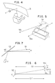
- a HUD unit I including the display unit and the optical system is located at a central position of the dash board, and a virtual image is reflected to the driver sitting on a driver's seat of the automobile.
- reflective points 19 on the windshield glass of the same virtual image reaching a right eye 16R and a left eye 16L of the driver are present at different positions because of binocular parallax.
- Fig. 6 shows a plan view of arrangement of the driver's eyes 16R and 16L, the HUD unit (shown as an object point I') and the reflective points on the windshield glass.
- the windshield glass is a plane glass for ease of explanation, there will be now described a problem under the following conditions.
- an average distance LI between the right and left eyes is about 70 mm
- a distance SI' between a center position between both the eyes 16L and 16R and a middle point between the reflective points on the windshield glass is about 850 mm.
- the virtual image is directed from the HUD unit I on a lower side of the eyes, and a vertical difference H between a middle point 19' between the reflective points and the eyes is about 30 mm.
- a distance L2 between a longitudinal line passing through the middle point 19' and the central position of both the eyes is about 210 mm.
- the windshield glass is inclined by 28 degrees at the middle point 19' with respect to a horizontal plane.
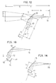
- a left reflective point 19L is slipped to a left lower position from a right reflective point 19R with respect to a plane formed by a y-axis extending in a vertical direction and a z-axis extending along a transverse direction of the automobile.
- a vertical difference between the reflective points 19L and 19R is 7.5 mm, while a transverse difference therebetween is 66.5 mm.
- a straight distance SI between the central position of both the eyes and the reflective points is 876 mm.
- the reflective image on the windshield glass is perceived double because of the aforementioned binocular parallax, which is naturally dependent upon a transverse dimension of the image. Basically, it is hard to adjust the human eyes in the vertical direction, and accordingly, if the identical image is received by the eyes for a long time with such binocular parallax, there will occur eye strain to create a serious problem from the viewpoint of prevention of danger. Further, although curvature of the windshield glass in the vertical and transverse directions is not taken into consideration as to the binocular parallax in the foregoing description, it will be appreciated that the slip of the virtual image is increased in the case that the curvature is considered.
- the HUD utilizing the windshield glass as a reflecting means has the problems of double reflection and binocular parallax. Unless the problems are solved, a clear display image cannot be visible perceived by the driver without eye strain.
- the optical system is designed in such that an angle of light beam of the virtual image incident upon the windshield glass is not more than a monocular resolving power on the basis of reflective conditions of the windshield glass.
- a double image of the virtual image entering the windshield glass is not perceived by a driver, but a clear and high-quality display image may be visibly perceived by the driver.
- the on-vehicle head up display device further comprises an optical means arranged between the optical system and the windshield glass to correct parallax of light beam of the virtual image reflected on the windshield glass. Accordingly, eye strain due to binocular parallax is not generated, but a clear and high-quality display image may be visibly perceived by the driver. Further, high drivability and safety may be imparted to the automobile.
- Beams of light incident upon the windshield glass are intended to be nearly parallel to each other, so as to reduce the influence of the double reflection on the windshield glass. For instance, if a reflective image enters the windshield glass from a point at infinity (or a far point near infinity), beams of incident light become nearly parallel to each other as shown in Fig. 9, and an apparent distance of the image becomes infinite. As a result, parallax of beams reflected on two interfaces of the windshield glass 13 is decreased. If the parallax is suppressed within a resolving power of a human eye 16 (monocular), that is, within 2 to 5 minutes, a double image as slipped is not perceived.
- a human eye 16 monoocular
- the distance between a virtual image and the human eye for the purpose of elimination of perception of the double image is obtained in the following manner.
- Fig. 10 shows light beams of an object point 17 incident upon the windshield glass 13 and reflected light beams directed to the eye 16 with respect to two reflective interfaces of the windshield glass 13.
- the light beams reflected on the two interfaces take different paths.
- An angle formed by each of two light beams on the incident side and the reflective side is represented by a.
- An incident and reflective angle measured on the inside interface of the windshield glass is represented by ⁇ 3.
- a distance between a reflective point on the inside interface of the windshield glass and an incident point of the beam directed to the inside interface is represented by 1 while a distance between the reflective point and an incident point of the beam directed to an outside interface of the windshield glass is represented by l 2 .
- a reflective angle ⁇ on the outside interface of the windshield glass is given by the low of refraction in the following manner.
- the distance D may be required to be more than the range of 500 to 2000 mm under the condition of a general driving position, installation position of the device and angle of the windshield glass. Naturally, if the distance D exceeds this distance, and approaches to infinity, the double image is eliminated.
- Fig. 12 shows only a display unit If formed by an LCD unit and an optical system 12 for the purpose of simplicity of the HUD unit I, in which a housing of the HUD unit, a dash board and the other elements are omitted.
- the display unit ll is arranged on a light axis of the optical system 12.
- the light axis of the optical system 12 is arranged so as to reflect the virtual image of the display image of the display unit II from a position below the inclined windshield glass 13 having curvature R to a driver's eye existing at a substantially horizontally rear position.
- the windshield glass is regarded as a plane glass. Further, it is assumed that a distance between the eye 16 and the virtual image present at a front position of the windsheild glass 13 is L; a distance between the eye 16 and the windshield glass 13 is C,; a distance between the optical system 12 and the windsheild glass 13 is C 2 ; and a distance between the windshield glass 13 and the virtual image is S. As the windshield glass 13 is assumed to be plane, it is not necessary to take magnification of the windshield glass 13 into consideration.
- a distance between the windshield glass 13 and the virtual image formed on a rear side of the display unit II and the optical system is equal to the distance S between the windshield glass 13 and the virtual image formed on a front side of the windshield glass 13.
- a size of both the virtual images is also equal to each other.
- the distance x' is given by the following equation with respect to a focal distance f and the distance x between the object PQ and the focal point F.
- the distance L is dependent upon not only the focal distance of the optical system and the position of the object, but also the position of the driver. Therefore, it is necessary to consider the position of the driver, so as to set an apparent distance of the image.
- x may be obtained by setting a value of L required for eliminating the double image, and determining p and f.
- the display unit II is located at the distance x as obtained to provide the on-vehicle HUD which may elimiante the double image.
- the windshield glass is generally so curved as to project toward a front side of an automobile, and functions as a concave mirror.
- no curvature of the windshield glass is taken into consideration. Therefore, even if the distances f and x in Equation (8) are set so as to form a display image at a predetermined distance, the double image cannot be effectively eliminated as desired.
- the optical system 12 and the windshield glass 13 are synthesized with each other to obtain a synthetic optical system 20 as shown in Fig. 15 which is equivalent to Fig. 14. Then, obtained are a synthetic focal distance f o of the synthetic optical system 20 and a distance between a center point H of the synthetic optical system 20 and a center point O of the optical system 12 shown in Fig. 13 so as to determine a mounting position of the display unit II.
- the windshield glass 13 having curvature R functions as a lens having a focal distance R/2.
- the synthetic focal distance f o obtained by synthesizing the windshield glass 13 and the optical system 12 having a focal distance f' may be given by the following equation.
- the distance y may be given by the following equation.
- the synthetic focal distance f a of the synthetic optical system 20 shown in Fig. 15 may be obtained by substituting these values into Equation (10) as follows:
- the position of the synthetic optical system 20 is determined at the distance of about 29.8 mm from the optical system 12.
- Equation (9) x is obtained from Equation (9) as follows:
- the apparent distance capable of suppressing image slip created by the double reflection on the windshield glass to a level less than the monocular resolving power is first obtained from each position of the windshield glass, the driver and the HUD unit. Then, the constitution of the optical system and the distance between the optical system and the display unit are determined.
- the apparent distance of about 20 m for the virtual image by the HUD may be obtained to thereby reduce the slip of the double image created by the double reflection on the windshield glass to such a degree that the slip is not perceived.
- extension of the apparent distance is preferable in view of the fact that a watching point in driving is present at a distance relatively far away from the driver.
- the display unit II is located at the distance of 197.9 mm from the optical system 12.
- the display unit II is located at the distance of 180.9 mm from the optical system 12.
- the difference can cause incapabilities of formation of a virtual image at a desired far point and elimination of the double image. Unless the virtual image may be formed at a desired far point, there is a possibility that the driver cannot visibly perceive a display image at an apparent distance in driving.
- the optical system preferably includes a large aperture lens so that the overall display image may be visibly perceived through the optical system even when a driver moves his head or adjusts his seat.
- mirrors la and Ib may be provided between the display unit 11 and the optical system 12 as shown in Fig. 16 so as to bend the light axis and decrease the overall length of the HUD unit.
- the reflective point on the windshield glass of the light image of the HUD which enters the right and left eyes is slipped by 66.5 mm in a horizontal direction and 7.5 mm in a vertical direction, and the binocular parallax 0 in the vertical direction is 0.49°.
- the binocular parallax in the horizontal direction provides stereoscopic vision, there will not occur so serious problem unless the horizontal slip of the reflective point is corrected. Accordingly, it is possible to obtain a satisfactory display image by correcting the binocular parallax in the vertical direction only even when oblique reflection is conducted.
- the binocular parallax in the vertical direction will reference to Figs 5 and 6 may be eliminated by upwardly moving the reflective point for the left eye by the distance of 7.5 mm.
- the display image may be visuallized more clearly.
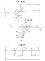
- the preferred embodiment employs a prism 30 to move light beam directed from the optical system of the HUD unit through the windshield glass to the left eye.
- the image of the display unit II is once reflected on a mirror la prior to entering the optical system 12 for the purpose or reducing a size of the HUD unit in the vertical direction of the dash board.
- Fig. 18 which shows details of the operation of the prism 30, light beam K L entering the left eye prior to correction is reflected at a reflective point B located below a reflective point A of light beam K R entering the right eye.
- the angle 8 formed between both the light beams after reflection means the binocular parallax in the vertical direction.
- the prism 30 is of a sectional shape such that an upper surface only is inclined and a portion on a front side of the vehicle body is thicker than that on a rear side thereof. Further, the prism 30 has different vertical angles such that the vertical angle on the left side where the light beam entering the left eye passes is larger, while the vertical angle on the right side where the light beam entering the right eye passes is smaller. Thus, the upper surface of the prism is curved.
- the section of the prism 30 shown in Fig. 18 is a section where the light beam K entering the left eye passes.
- the light beam K R entering the right eye passes through a section of the prism 30 present on a back side of the drawing (corresponding to a right-hand side of the vehicle body).
- the vertical angle of the prism 30 at the section where the light beam K R passes is smaller, and the light beam K R passes at the substantially same position as with the case that the correction by the prism is not carried out.
- the light beam K L ' passes through the section having a larger vertical angle, and is refracted by the correction angle ⁇ . Then, the light beam K L ' is reflected at a point B' present at the same level as of a reflective point A of the light beam K R .
- both the light beams K L ' and K R entering the left and right eyes advance on a horizontal plane envolving both the eyes by the operation of the prism, thereby eliminating the binocular parallax in the vertical direction and obtaining a clear display image.
- a tilt angle of the light beam K L ' is different from that of the light beam K R prior to reflection on the windshield glass, a direction of a perpendicular Bat the reflective point B' is naturally different from that of a perpendicular A v at the reflective point A.
- a width b of the prism 30 is about 130 mm, and a depth a is about 53 mm in consideration of an aspect ratio of the display image, provided that an effective diameter ⁇ is 120 mm, and a horizontal distance between both the reflective points A and B is 1.80 times 66.5 mm.
- a thickness t is 1.0 mm, and a refractive index n of the prism 30 made of glass is 1.492.
- a necessary refractive angle with respect to a maximum vertical angle ⁇ o on the x-axis and the refractive index n in Fig. 19 is as follows:
- Fig. 20 shows a contour of the height z of the prism on the x-y plane according to Equation (14). As is apparent from Fig. 20, the upper surface of the prism 30 is curved in such a manner that a left front portion is thick, while a right rear portion is thin.
- the binocular parallax in the vertical direction may be eliminated to enable the driver to visibly perceive a high-quality display image without eye strain.
- curvature of the windshield glass is not taken into consideration in Figs. 19 and 20, the curvature may be reflected on the shape of the prism to obtain a display image with no parallax in the case that the windshield glass is curved, and especially, it is largely curved in a transverse direction.
- the mirror la is provided between the display unit II and the optical system 12 in the foregoing preferred embodiment shown in Fig. 17, the display unit II may be located on the light axis of the optical system 12 without providing the mirror la.
- the aforementioned preferred embodiment employs a single convex lens for the optical system 12, a combination lens formed by combining a plurality of lenses may be of course used for the optical system 12.
- an angle formed by light beams of the virtual image to enter the windshield is rendered less than a monocular resolving power on an assumption that the thickness of the windshield glass is constant in the above embodiment whereas the effect of rendering said angle may be obtained by making the windshield glass thinner.
Abstract
Description
- The present invention relates to an on-vehicle head up display device, and more particularly to an on-vehicle head up display device utilizing a windshield glass of an automobile and indicating various information with use of a virtual image optical system.
- There has been proposed a device for indicating a vehicle speed, time, engine rotational speed and other information by utilizing reflection on an inner surface of the windshield glass of the automobile and forming a virtual image at a front position of the windshield glass. Such a device is called an on-vehicle head up display device (which will be hereinafter referred to as HUD).
- Figs. I and 2 show a fundamental construction of the HUD in the prior art. As shown in Fig. the HUD is constituted of a display unit II installed at a center position of a dash board, for example, a (dioptric)
optical system 12 such as a lens, and a catoptric system using awindshield glass 13. The display unit II employs LED, LCD and the like. A small image of thedisplay unit 11 is enlarged by theoptical system 12 and the virtual image optical system formed by thewindshield glass 13, and is formed as a virtual image at a front position of thewindshield glass 13. - Accordingly, as shown in Fig. 2, the virtual image (indication of speed, in this case) indicated by the display unit II of the HUD is perceived by a driver as if the display image were present at a fixed distance in front of an
automobile 14. - An image formation technique such that display information by LED or LCD and image information such as visible framework are formed in a fixed optical field is traditionally used in a camera finder, for example. A technique in the HUD is basically similar to such a display technique as mentioned above. However, the technique in the HUD includes some problems to be solved in such a point that the windshield glass is used as the catoptric system.
- One of the problems is caused by the use of the windshield glass as a half mirror having a relatively high transmittance. As shown in Fig. 3, light beam directed from a point on the
display unit 11 through theoptical system 12 to thewindshield glass 13 is reflected on two interfaces between air and glass on the outside and inside of the automobile. Further, as the optical system of the HUD is primarily provided on the dash board, it is necessary to set large an incident and reflective angle to the windshield glass. As a result, reflective images as reflected on the two reflective surfaces are slipped to generate perception of a double image. - Namely, referring to Fig. 3, the light generated from a point on the display unit II is allowed to enter the windshield glass in the form of beam from an
object point 17 on a virtual image formed by theoptical system 12. Therefore, the beam is reflected on the two reflection interfaces of thewindshield glass 13, and is allowed to enter driver'seyes 16 along two paths as shown by solid lines. This is caused by refraction at the interface between glass and air on the outside of the windshield glass. Owing to such a slip of the light path, the virtual image of theobject point 17 is perceived double as shown bynumerals 17", and accordingly, the driver cannot visibly perceive a clear display image. - To solve this problem, it is considered that the windshield glass is treated by coating to form a mirror or half mirror having a high reflectance on an inner surface of the windshield glass. However, it is undesirable in traffic safety to provide such a mirror portion for the windshield glass of the automobile in the vicinity of the dash board. Specifically, a lower area of the windshield glass plays an important role for the driver since he watches a fender part of the vehicle body so as to grasp a condition of the vehicle body. Therefore, if the visibility of the lower area of the windshield glass is hindered, the drivability is very reduced. Furthermore, poor visibility of the windshield glass causes hindrance in quick perception of any obstacle existing in front of the automobile, resulting in traffic danger.
- In addition to the aforementioned problem of double image due to double reflection, there exists another problem of binocular parallax generated primarily in dependence upon a direction of reflection.
- As shown in Fig. 4, a HUD unit I including the display unit and the optical system is located at a central position of the dash board, and a virtual image is reflected to the driver sitting on a driver's seat of the automobile. In this case, as shown in Fig. 5,
reflective points 19 on the windshield glass of the same virtual image reaching aright eye 16R and aleft eye 16L of the driver are present at different positions because of binocular parallax. - Fig. 6 shows a plan view of arrangement of the driver's
eyes - Provided that the windshield glass is a plane glass for ease of explanation, there will be now described a problem under the following conditions.
- Referring to Fig. 6, an average distance LI between the right and left eyes is about 70 mm, and a distance SI' between a center position between both the
eyes - In other words, light beam from the HUD unit I located at a lower position on a left-hand side (in case of a right steering wheel) is allowed to enter the windshield glass, and the reflective light advances toward the eyes present at an upper position on a right-hand side of the reflective points.
- Under the aforementioned conditions, as shown in Fig. 8, a left reflective point 19L is slipped to a left lower position from a right
reflective point 19R with respect to a plane formed by a y-axis extending in a vertical direction and a z-axis extending along a transverse direction of the automobile. In this case, when thereflective points 19L and 19R are projected onto the y-z plane, a vertical difference between thereflective points 19L and 19R is 7.5 mm, while a transverse difference therebetween is 66.5 mm. - As calculated from the conditions set forth above in conjunction with Fig. 6, that is, the distance SI' (850 mm), the vertical difference H (30 mm) and the distance L2 (210 mm), a straight distance SI between the central position of both the eyes and the reflective points is 876 mm. In this case, binocular parallax 0 (= tan-1(7.5/876)) in the vertical direction owing to the vertical difference of 7.5 mm between the reflective points.
- Consequently, the reflective image on the windshield glass is perceived double because of the aforementioned binocular parallax, which is naturally dependent upon a transverse dimension of the image. Basically, it is hard to adjust the human eyes in the vertical direction, and accordingly, if the identical image is received by the eyes for a long time with such binocular parallax, there will occur eye strain to create a serious problem from the viewpoint of prevention of danger. Further, although curvature of the windshield glass in the vertical and transverse directions is not taken into consideration as to the binocular parallax in the foregoing description, it will be appreciated that the slip of the virtual image is increased in the case that the curvature is considered.
- As is described above, the HUD utilizing the windshield glass as a reflecting means has the problems of double reflection and binocular parallax. Unless the problems are solved, a clear display image cannot be visible perceived by the driver without eye strain.
- Accordingly, it is a primary object of the present invention to provide an on-vehicle head up display device using a windshield glass as a reflection means, which enables a driver to visibly perceive a clear display image without eye strain.
- It is another object of the present invention to provide an on-vehicle head up display device which may eliminate double reflection.
- It is a further object of the present invention to provide an on-vehicle head up display device which may eliminate binocular parallax.
- It is a still further object of the present invention to provide an on-vehicle head up display device which enables a driver to always visibly perceive an overall display image.
- It is a still further object of the present invention to provide an on-vehicle head up display device which is compact and of a short depth.
- The on-vehicle head up display device according to the present invention using a windshield glass of an automobile as a catoptric system to project a display image onto an inner surface of the windshield glass comprises a display means for indicating various information and an optical system for letting a virtual image of the display image indicated by the display means enter the windshield glass. The optical system is designed in such that an angle of light beam of the virtual image incident upon the windshield glass is not more than a monocular resolving power on the basis of reflective conditions of the windshield glass.
- Accordingly, a double image of the virtual image entering the windshield glass is not perceived by a driver, but a clear and high-quality display image may be visibly perceived by the driver.
- The on-vehicle head up display device according to the present invention further comprises an optical means arranged between the optical system and the windshield glass to correct parallax of light beam of the virtual image reflected on the windshield glass. Accordingly, eye strain due to binocular parallax is not generated, but a clear and high-quality display image may be visibly perceived by the driver. Further, high drivability and safety may be imparted to the automobile.
-
- Fig. I is an illustration showing a fundamental construction of the HUD;
- Fig. 2 is an illustration showing projection of a display image;
- Fig. 3 is an illustration showing generation of a double image on a windshield glass;
- Figs. 4 to 8 show illustrations showing generation of binocular parallax in the HUD;
- Fig. 9 is a schematic illustration showing a double reflection preventing technique according to the present invention;
- Figs. 10 and II are illustrations showing a fundamental principle of a double image preventing technique according to the present invention;
- Fig. 12 is a schematic illustration showing an arrangement of the HUD according to the present invention;
- Fig. 13 is an illustration showing a virtual image optical system of the device shown in Fig. 12;
- Fig. 14 is a schematic illustration showing the arrangement of the HUD according to the present invention when applied to a windshield glass having curvature;
- Fig. i5 is an illustration showing a virtual image optical system of the device shown in Fig. 14;
- Fig. 16 is an illustration showing a modified embodiment of the device shown in Fig. 14;
- Fig. 17 is an illustration showing a modified embodiment of the HUD according to the present invention;
- Fig. 18 is an illustration showing the operation of a prism shown in Fig. 17;
- Fig. 19 is a perspective view of the prism shown in Fig. 17; and
- Fig. 20 is a graph showing a shape of the prism shown in Fig. 17.
- There will be now described a preferred embodiment of the present invention with reference to the drawings.
- First, described is a technique for eliminating influence of double reflection on a windshield glass.
- Beams of light incident upon the windshield glass are intended to be nearly parallel to each other, so as to reduce the influence of the double reflection on the windshield glass. For instance, if a reflective image enters the windshield glass from a point at infinity (or a far point near infinity), beams of incident light become nearly parallel to each other as shown in Fig. 9, and an apparent distance of the image becomes infinite. As a result, parallax of beams reflected on two interfaces of the
windshield glass 13 is decreased. If the parallax is suppressed within a resolving power of a human eye 16 (monocular), that is, within 2 to 5 minutes, a double image as slipped is not perceived. - The distance between a virtual image and the human eye for the purpose of elimination of perception of the double image is obtained in the following manner.
- Fig. 10 shows light beams of an
object point 17 incident upon thewindshield glass 13 and reflected light beams directed to theeye 16 with respect to two reflective interfaces of thewindshield glass 13. The light beams reflected on the two interfaces take different paths. An angle formed by each of two light beams on the incident side and the reflective side is represented by a. An incident and reflective angle measured on the inside interface of the windshield glass is represented by {3. A distance between a reflective point on the inside interface of the windshield glass and an incident point of the beam directed to the inside interface is represented by 1 while a distance between the reflective point and an incident point of the beam directed to an outside interface of the windshield glass is represented by ℓ2. Further, a distance between theobject point 17 and the reflective point on the inside interface of the windshield glass is represented by D, while a distance between the reflective point and theeye 16 is represented by S. Then, the following equation is obtained by the law of sines.


- Assuming that S is constant, that is, a driving position of a driver is fixed, if D - ∞ ℓ1/ℓ2 - 0 is given. In other words, the more D increases, the smaller 1, becomes, and the angle a is also decreased.
- Assuming that a thickness of the
windshield glass 13 is 5 mm, and a refractive index of thewindshield glass 13 is 1.5, it is studied to obtain a = 0.08° corresponding to a substantially maximum value, 4.8 minutes in a dispersion of the monocular resolving power if β = 45°. Referring to Fig. II, a reflective angle θ on the outside interface of the windshield glass is given by the low of refraction in the following manner.

- From the above equations, t, + ℓ2 = 5.34 mm is given, and t, = 1.35 mm is given from Equation (I). Therefore, ℓ2 = 3.99 mm is given. Accordingly, D = 2020 mm is given from Equation (3).
- Consequently, in order to obtain a = 0.08° corresponding to 4.8 minutes if, the thickness of the
windshield glass 13 is 5 mm, and the refractive index is 1.5, and the incident angle from a HUD unit is 45°, it is required to take the distance of about 2020 mm between the object point (or a virtual image) and thewindshield glass 13. - In the case of obtaining the same angle a with the incident angle β from the HUD unit made smaller, e.g., β = 30°, D = 580 mm is given by the same manner as the above. Further, in the case that the angle a is reduced to 0.035° corresponding to a minimum value, 2.1 minutes of the monocular resolving power, D = 2190 mm is given with = 30°.
- The foregoing setting is merely one example for explaining the theory of elimination of double images, and as there are actually included difference in the driver's seat position and front and rear margins for seat adjustment, a proper distance D is naturally dependent upon an automobile on which the device is mounted. To obtain the effect of prevention of the double image, the distance D may be required to be more than the range of 500 to 2000 mm under the condition of a general driving position, installation position of the device and angle of the windshield glass. Naturally, if the distance D exceeds this distance, and approaches to infinity, the double image is eliminated.
- Although there is proposed in the HUD a system such that an image of LCD, etc. is directed to enter the windshield glass directly, it is actually unable to locate a display image at a point in the above-mentioned range in view of a vehicle body size. Therefore, in this embodiment, a virtual image of the display image is let enter the windshield glass with use of an optical system of the HUD unit, and the distance between the virtual image and the windshield glass is extended to a far point where the double image is not perceived.
- Fig. 12 shows only a display unit If formed by an LCD unit and an
optical system 12 for the purpose of simplicity of the HUD unit I, in which a housing of the HUD unit, a dash board and the other elements are omitted. The display unit ll is arranged on a light axis of theoptical system 12. The light axis of theoptical system 12 is arranged so as to reflect the virtual image of the display image of the display unit II from a position below theinclined windshield glass 13 having curvature R to a driver's eye existing at a substantially horizontally rear position. - For the purpose of simplicity of explanation, the windshield glass is regarded as a plane glass. Further, it is assumed that a distance between the
eye 16 and the virtual image present at a front position of thewindsheild glass 13 is L; a distance between theeye 16 and thewindshield glass 13 is C,; a distance between theoptical system 12 and thewindsheild glass 13 is C2; and a distance between thewindshield glass 13 and the virtual image is S. As thewindshield glass 13 is assumed to be plane, it is not necessary to take magnification of thewindshield glass 13 into consideration. Further, as the light axis is merely bent by thewindshield glass 13, a distance between thewindshield glass 13 and the virtual image formed on a rear side of the display unit II and the optical system is equal to the distance S between thewindshield glass 13 and the virtual image formed on a front side of thewindshield glass 13. Further, a size of both the virtual images is also equal to each other. - The above-mentioned constitution is equivalent to that shown in Fig. 13 if invertion of the image by the windshield glass is ignored. In the case that an erecting virtual image is intended to be obtained with the constitution shown in Fig. 13, an object PQ (corresponding to the display unit II) having a size Y is located at a distance x inside of a focal point F of the
optical system 12, while the eye is located at a distance p outside of a focal point F'. Assuming that a distance between the eye and a virtual image P'Q' of the object is represented by L, and a distance between the focal point F' and the virtual image P'Q' is represented by x', a lateral magnification β is given by the following equation.
- The distance x' is given by the following equation with respect to a focal distance f and the distance x between the object PQ and the focal point F.

- Since the distance x' is also represented by x' = L + p, this equation is solved for L to give the following solution.

- As is apparent from Equation (8), the distance L is dependent upon not only the focal distance of the optical system and the position of the object, but also the position of the driver. Therefore, it is necessary to consider the position of the driver, so as to set an apparent distance of the image.
- Accordingly, in the following equation as modified from Equation (8), x may be obtained by setting a value of L required for eliminating the double image, and determining p and f.

- Then, the display unit II is located at the distance x as obtained to provide the on-vehicle HUD which may elimiante the double image.
- However, the windshield glass is generally so curved as to project toward a front side of an automobile, and functions as a concave mirror. In the aforementioned device, no curvature of the windshield glass is taken into consideration. Therefore, even if the distances f and x in Equation (8) are set so as to form a display image at a predetermined distance, the double image cannot be effectively eliminated as desired.
- In the case that the
windshield glass 13 having curvature is used as a catoptric system as shown in Fig. 14, theoptical system 12 and thewindshield glass 13 are synthesized with each other to obtain a syntheticoptical system 20 as shown in Fig. 15 which is equivalent to Fig. 14. Then, obtained are a synthetic focal distance fo of the syntheticoptical system 20 and a distance between a center point H of the syntheticoptical system 20 and a center point O of theoptical system 12 shown in Fig. 13 so as to determine a mounting position of the display unit II. - The
windshield glass 13 having curvature R functions as a lens having a focal distance R/2. The synthetic focal distance fo obtained by synthesizing thewindshield glass 13 and theoptical system 12 having a focal distance f' may be given by the following equation.

- In the on-vehicle HUD shown in Fig. 14, assuming that the focal distance f' of the
optical system 12 is 200 mm, and the curvature R of thewindshield glass 13 is 5000 mm, and the distance C2 between theoptical system 12 and thewindshield glass 13 is 350 mm, the synthetic focal distance fa of the syntheticoptical system 20 shown in Fig. 15 may be obtained by substituting these values into Equation (10) as follows:
- Therefore, fa = 213 mm is obtained. Similarly, the distance y may be obtained by substituting the above values into Equation (II) as follows:

- Therefore, the position of the synthetic
optical system 20 is determined at the distance of about 29.8 mm from theoptical system 12. - Further, assuming that L is 20000 mm, and the distance C, + C2 between the
optical system 12 and the driver'seye 16 is 813 mm, p = 600 is obtained, and x is obtained from Equation (9) as follows:
- Therefore, it is necessary to locate the display unit II at the distance of 2.3 mm from the focal point F of the synthetic
optical system 20 to theoptical system 12. - In summary, the apparent distance capable of suppressing image slip created by the double reflection on the windshield glass to a level less than the monocular resolving power is first obtained from each position of the windshield glass, the driver and the HUD unit. Then, the constitution of the optical system and the distance between the optical system and the display unit are determined.
- In this manner, the apparent distance of about 20 m for the virtual image by the HUD may be obtained to thereby reduce the slip of the double image created by the double reflection on the windshield glass to such a degree that the slip is not perceived. Especially, extension of the apparent distance is preferable in view of the fact that a watching point in driving is present at a distance relatively far away from the driver.
- For the purpose of comparison between both the devices shown in Figs. 13 and 15, the position of the display unit It of the HUD shown in Fig. 13 is obtained as follows:

- As a result, the display unit II is located at the distance of 197.9 mm from the
optical system 12. To the contrary, in the on-vehicle HUD of the present invention, the display unit II is located at the distance of 180.9 mm from theoptical system 12. Namely, the difference of 17 mm in the position of the display unit II is present between the present invention and the prior art. The difference can cause incapabilities of formation of a virtual image at a desired far point and elimination of the double image. Unless the virtual image may be formed at a desired far point, there is a possibility that the driver cannot visibly perceive a display image at an apparent distance in driving. - The optical system preferably includes a large aperture lens so that the overall display image may be visibly perceived through the optical system even when a driver moves his head or adjusts his seat.
- In the case that the distance a between the optical system and the display unit is required to be remarkably enlarged because of other conditions, and an overall length of the HUD unit is increased to the extent that it cannot be received in the dash board, mirrors la and Ib may be provided between the
display unit 11 and theoptical system 12 as shown in Fig. 16 so as to bend the light axis and decrease the overall length of the HUD unit. - There will be now described a technique for preventing binocular parallax.
- As previously set forth with reference to Figs. 5 and 6, the reflective point on the windshield glass of the light image of the HUD which enters the right and left eyes is slipped by 66.5 mm in a horizontal direction and 7.5 mm in a vertical direction, and the binocular parallax 0 in the vertical direction is 0.49°. -
- As is appreciated from the fact that the binocular parallax in the horizontal direction provides stereoscopic vision, there will not occur so serious problem unless the horizontal slip of the reflective point is corrected. Accordingly, it is possible to obtain a satisfactory display image by correcting the binocular parallax in the vertical direction only even when oblique reflection is conducted.
- In other words, the binocular parallax in the vertical direction will reference to Figs 5 and 6 may be eliminated by upwardly moving the reflective point for the left eye by the distance of 7.5 mm. As a result, the display image may be visuallized more clearly.
- As shown in Fig. 17, the preferred embodiment employs a
prism 30 to move light beam directed from the optical system of the HUD unit through the windshield glass to the left eye. In this embodiment, the image of the display unit II is once reflected on a mirror la prior to entering theoptical system 12 for the purpose or reducing a size of the HUD unit in the vertical direction of the dash board. - Referring to Fig. 18 which shows details of the operation of the
prism 30, light beam KL entering the left eye prior to correction is reflected at a reflective point B located below a reflective point A of light beam KR entering the right eye. The angle 8 formed between both the light beams after reflection means the binocular parallax in the vertical direction. - As shown in Fig. 19, the
prism 30 is of a sectional shape such that an upper surface only is inclined and a portion on a front side of the vehicle body is thicker than that on a rear side thereof. Further, theprism 30 has different vertical angles such that the vertical angle on the left side where the light beam entering the left eye passes is larger, while the vertical angle on the right side where the light beam entering the right eye passes is smaller. Thus, the upper surface of the prism is curved. - When the virtual image of the display image is projected through the
prism 30 under the conditions set forth in conjunction with Figs. 5 and 6, the light beam entering the left eye is moved as shown by KL'. - The section of the
prism 30 shown in Fig. 18 is a section where the light beam K entering the left eye passes. On the other hand, the light beam KR entering the right eye passes through a section of theprism 30 present on a back side of the drawing (corresponding to a right-hand side of the vehicle body). The vertical angle of theprism 30 at the section where the light beam KRpasses is smaller, and the light beam K R passes at the substantially same position as with the case that the correction by the prism is not carried out. On the other hand, the light beam KL' passes through the section having a larger vertical angle, and is refracted by the correction angle θ. Then, the light beam KL' is reflected at a point B' present at the same level as of a reflective point A of the light beam KR. - Thus, both the light beams KL' and K R entering the left and right eyes advance on a horizontal plane envolving both the eyes by the operation of the prism, thereby eliminating the binocular parallax in the vertical direction and obtaining a clear display image. However, since a tilt angle of the light beam KL' is different from that of the light beam KR prior to reflection on the windshield glass, a direction of a perpendicular Bat the reflective point B' is naturally different from that of a perpendicular A v at the reflective point A.
- Referring to Fig. 19 which shows an example of the prism used for the purpose of eliminating the binocular parallax of 0.49°, a width b of the
prism 30 is about 130 mm, and a depth a is about 53 mm in consideration of an aspect ratio of the display image, provided that an effective diameter ∅ is 120 mm, and a horizontal distance between both the reflective points A and B is 1.80 times 66.5 mm. Assuming that a bottom surface of theprism 30 is perpendicular to the light axis of theoptical system 12, a thickness t is 1.0 mm, and a refractive index n of theprism 30 made of glass is 1.492. - A necessary refractive angle with respect to a maximum vertical angle θo on the x-axis and the refractive index n in Fig. 19 is as follows:

- An angular change θT in a longitudinal direction of the
prism 30 is θT = 1.80 θo, and Equation (12) is modified to obtain
- Hence, θ° = 1.00 and θT = 1.8° are obtained.
- A height (thickness) z of the
prism 30 is represented as follows:
- The aforementioned dimensions and angle are substituted in Equation (13) to obtain

- Fig. 20 shows a contour of the height z of the prism on the x-y plane according to Equation (14). As is apparent from Fig. 20, the upper surface of the
prism 30 is curved in such a manner that a left front portion is thick, while a right rear portion is thin. - In this way, when the display image is obliquely reflected in the course of HUD -windshield glass - driver's eyes, the binocular parallax in the vertical direction may be eliminated to enable the driver to visibly perceive a high-quality display image without eye strain. Although curvature of the windshield glass is not taken into consideration in Figs. 19 and 20, the curvature may be reflected on the shape of the prism to obtain a display image with no parallax in the case that the windshield glass is curved, and especially, it is largely curved in a transverse direction.
- Further, although the mirror la is provided between the display unit II and the
optical system 12 in the foregoing preferred embodiment shown in Fig. 17, the display unit II may be located on the light axis of theoptical system 12 without providing the mirror la. - Additionally, the aforementioned preferred embodiment employs a single convex lens for the
optical system 12, a combination lens formed by combining a plurality of lenses may be of course used for theoptical system 12. - It is further noted that an angle formed by light beams of the virtual image to enter the windshield is rendered less than a monocular resolving power on an assumption that the thickness of the windshield glass is constant in the above embodiment whereas the effect of rendering said angle may be obtained by making the windshield glass thinner.
Claims (10)
- l. In an on-vehicle head up display device employing a catoptric system for a windshield glass of an automobile to project a display image onto an inner surface of said windshield glass, the improvement comprising a display means for indicating various information, and an optical system for letting a virtual image of said display image of said display means enter said windshield glass, said optical system being adapted to make an angle formed by light beams of said virtual image entering said windshield glass less than a monocular resolving power according to reflective conditions of said windshield glass.
- 2. The on-vehicle head up display device as defined in claim I, wherein said monocular resolving power is five minutes.
- 3. The on-vehicle head up display device as defined in claim I, wherein said optical system is synthesized with said windshield glass having curvature to form a synthetic optical system, said synthetic optical system forming a virtual image of said display image and letting said virtual image enter said windshield glass.
- 4. The on-vehicie head up display device as defined in claim I, wherein said optical system comprises a lens system having a large aperture ratio.
- 5. The on-vehicle head up display device as defined in claim I, further comprising another catoptric system provided on a light axis between said display means and said optical system for reflecting said display image of said display means to let said display image enter said optical system.
- 6. The on-vehicle head up display device as defined in claim 1, further comprising an optical means provided between said optical system and said windshield glass for correcting parallax of light beams of said virtual image reflected on said windshield glass.
- 7. The on-vehicle head up display device as defined in claim 6, wherein said optical means is adapted to correct vertical parallax of said light beams of said virtual image from said windshield glass.
- 8. The on-vehicle head up display device as defined in claim 6, wherein said optical means comprises a prism.
- 9. In an on-vehicle head up display device employing a catoptric system for a windshield glass of an automobile to project a display image onto an inner surface of said windshield glass, the improvement comprising a display means for indicating various information, and an optical system for letting a virtual image of said display image of said display means enter said windshield glass, said optical system forming said virtual image of said display image of said display means at a distance of 3 M. or more from said windshield glass.
- 10. In an on-vehicle head up display device employing a catoptric system for a windshield glass of an automobile to project a display image onto an inner surface of said windshield glass, the improvement comprising a display means for indicating various information, an optical system for letting said virtual image of said display image of said display means enter a part of said windshield glass slantwise, and an optical means for correcting parallax of light beams of said virtual image reflected on said windshield glass, said optical system being adapted to make an angle formed by light beams incident upon said windshield glass less than a monocular resolving power.
Applications Claiming Priority (4)
| Application Number | Priority Date | Filing Date | Title |
|---|---|---|---|
| JP61011123A JPS62173336A (en) | 1986-01-23 | 1986-01-23 | Head-up display device for vehicle mount |
| JP11123/86 | 1986-01-23 | ||
| JP68467/86 | 1986-03-28 | ||
| JP61068467A JPH0659787B2 (en) | 1986-03-28 | 1986-03-28 | Automotive heads-up display device |
Publications (3)
| Publication Number | Publication Date |
|---|---|
| EP0229876A2 true EP0229876A2 (en) | 1987-07-29 |
| EP0229876A3 EP0229876A3 (en) | 1988-04-27 |
| EP0229876B1 EP0229876B1 (en) | 1992-04-08 |
Family
ID=26346518
Family Applications (1)
| Application Number | Title | Priority Date | Filing Date |
|---|---|---|---|
| EP86112835A Expired - Lifetime EP0229876B1 (en) | 1986-01-23 | 1986-09-17 | On-vehicle head up display device |
Country Status (3)
| Country | Link |
|---|---|
| US (2) | US4787711A (en) |
| EP (1) | EP0229876B1 (en) |
| DE (1) | DE3684772D1 (en) |
Cited By (9)
| Publication number | Priority date | Publication date | Assignee | Title |
|---|---|---|---|---|
| EP0312117A2 (en) * | 1987-10-16 | 1989-04-19 | Bayerische Motoren Werke Aktiengesellschaft, Patentabteilung AJ-3 | Vehicle head-up display |
| US4962998A (en) * | 1987-09-07 | 1990-10-16 | Yazaki Corporation | Indication display unit for vehicles |
| US4973139A (en) * | 1989-04-07 | 1990-11-27 | Hughes Aircraft Company | Automotive head-up display |
| EP0450058A1 (en) * | 1989-10-16 | 1991-10-09 | Libbey-Owens-Ford Co. | Display panel for a vehicle windshield |
| EP0477149A2 (en) * | 1990-09-20 | 1992-03-25 | SOCIETA' ITALIANA VETRO- SIV-SpA | Head-up display device for the display of data aboard automobiles |
| US5143796A (en) * | 1990-03-12 | 1992-09-01 | Societa Italiana Vetro - Siv - S.P.A. | Glass windshield for motor vehicles with combined capabilities of sun radiation screen and image combiner |
| US5812332A (en) * | 1989-09-28 | 1998-09-22 | Ppg Industries, Inc. | Windshield for head-up display system |
| GB2498715A (en) * | 2012-01-20 | 2013-07-31 | Bae Systems Plc | Head up display providing two non-coincident virtual images |
| CN110794580A (en) * | 2018-08-03 | 2020-02-14 | 深圳前海智云谷科技有限公司 | Automobile head-up display system and installation method thereof and method for eliminating double images |
Families Citing this family (44)
| Publication number | Priority date | Publication date | Assignee | Title |
|---|---|---|---|---|
| DE3822222A1 (en) * | 1988-07-01 | 1990-01-04 | Bosch Gmbh Robert | DEVICE FOR HEAD-UP DISPLAYS ON MOTOR VEHICLES |
| JPH0651451B2 (en) * | 1987-03-17 | 1994-07-06 | 矢崎総業株式会社 | Vehicle display |
| JPH0626434Y2 (en) * | 1987-03-18 | 1994-07-20 | 矢崎総業株式会社 | Heads-up display device for vehicles |
| GB2204421B (en) * | 1987-04-15 | 1991-01-16 | Yazaki Corp | Display apparatus for a vehicle |
| GB2203855B (en) * | 1987-04-16 | 1990-10-03 | Yazaki Corp | Display apparatus for a vehicle |
| GB2203883B (en) * | 1987-04-16 | 1990-07-18 | Yazaki Corp | Display apparatus for automotive vehicle |
| DE3812648A1 (en) * | 1987-04-16 | 1988-11-03 | Yazaki Corp | DISPLAY DEVICE FOR A VEHICLE |
| US5028912A (en) * | 1988-02-03 | 1991-07-02 | Yazaki Corporation | Display apparatus for automotive vehicle |
| US5034732A (en) * | 1988-02-05 | 1991-07-23 | Yazaki Corporation | Head up display apparatus for automotive vehicle |
| JP2650358B2 (en) * | 1988-10-06 | 1997-09-03 | 株式会社ニコン | Optical device having semi-transmissive member |
| US5013135A (en) * | 1989-07-10 | 1991-05-07 | Matsushita Electric Industrial Co., Ltd. | Head-up display with two fresnel lenses |
| US5212471A (en) * | 1989-10-27 | 1993-05-18 | Hughes Aircraft Company | Polarized heads up display |
| JPH0643827Y2 (en) * | 1990-01-18 | 1994-11-14 | 矢崎総業株式会社 | Display device |
| AU2896792A (en) * | 1991-10-24 | 1993-05-21 | Oded Arnon | Biocular head-up display with separated fields |
| US5461499A (en) * | 1992-05-29 | 1995-10-24 | Yazaki Corporation | Non-regular reflection type holographic mirror and method of producing the same in a reflection type display apparatus for vehicle |
| US5535025A (en) * | 1994-02-01 | 1996-07-09 | Hughes Training, Inc. | Helmet mounted off axis liquid crystal display with a fiber optic wedge and a curved reflector |
| FR2717795B1 (en) * | 1994-03-22 | 1996-05-24 | Saint Gobain Vitrage | Vehicle glazing and plastic sheet used in this glazing. |
| US20070135982A1 (en) | 1995-06-07 | 2007-06-14 | Automotive Technologies International, Inc. | Methods for Sensing Weight of an Occupying Item in a Vehicular Seat |
| US7860626B2 (en) * | 1995-06-07 | 2010-12-28 | Automotive Technologies International, Inc. | Vehicular heads-up display system with adjustable viewing |
| US20060284839A1 (en) * | 1999-12-15 | 2006-12-21 | Automotive Technologies International, Inc. | Vehicular Steering Wheel with Input Device |
| US5912700A (en) * | 1996-01-10 | 1999-06-15 | Fox Sports Productions, Inc. | System for enhancing the television presentation of an object at a sporting event |
| US6847336B1 (en) * | 1996-10-02 | 2005-01-25 | Jerome H. Lemelson | Selectively controllable heads-up display system |
| US5953077A (en) * | 1997-01-17 | 1999-09-14 | Fox Sports Productions, Inc. | System for displaying an object that is not visible to a camera |
| US6580562B2 (en) * | 2000-07-24 | 2003-06-17 | Yazaki Corporation | On-vehicle display unit |
| JP2002202475A (en) * | 2000-12-28 | 2002-07-19 | Yazaki Corp | Display device for vehicle |
| US20080198372A1 (en) * | 2007-02-21 | 2008-08-21 | Spatial Photonics, Inc. | Vehicle headlight with image display |
| JP2011053386A (en) * | 2009-09-01 | 2011-03-17 | Seiko Epson Corp | Display device, electronic equipment, and projection-type video apparatus |
| US8299938B2 (en) * | 2009-09-08 | 2012-10-30 | Rosemount Inc. | Projected instrument displays for field mounted process instruments |
| DE102011118134B4 (en) * | 2011-11-10 | 2021-12-16 | Kostal Automobil Elektrik Gmbh & Co. Kg | Camera arrangement for a motor vehicle |
| JP5941292B2 (en) * | 2012-02-10 | 2016-06-29 | 矢崎総業株式会社 | Vehicle display device |
| EP3693203B1 (en) * | 2014-12-10 | 2022-05-18 | Ricoh Company, Ltd. | Controller, display, method and carrier means for information provision |
| US11124116B2 (en) | 2014-12-12 | 2021-09-21 | Serge B. HOYDA | System and process for viewing in blind spots |
| US10138672B2 (en) | 2014-12-12 | 2018-11-27 | Serge B. HOYDA | Mounting system for a camera |
| US11518309B2 (en) | 2014-12-12 | 2022-12-06 | Serge Hoyda LLC | System and process for viewing in blind spots |
| WO2016094801A1 (en) * | 2014-12-12 | 2016-06-16 | Hoyda Serge B | System and process for viewing in blind spots |
| US10125918B2 (en) | 2014-12-12 | 2018-11-13 | Serge B. HOYDA | Mounting system for a camera |
| WO2016208196A1 (en) * | 2015-06-26 | 2016-12-29 | パナソニックIpマネジメント株式会社 | Head-up display and moving body equipped with head-up display |
| FR3067821B1 (en) * | 2017-06-19 | 2021-03-12 | Peugeot Citroen Automobiles Sa | HEAD-UP DISPLAY DEVICE FOR VEHICLE |
| JP6593393B2 (en) * | 2017-07-11 | 2019-10-23 | 株式会社Jvcケンウッド | Virtual image display device |
| JP2019086766A (en) | 2017-11-09 | 2019-06-06 | 日東電工株式会社 | Head-up display device |
| US20190161010A1 (en) * | 2017-11-30 | 2019-05-30 | Panasonic Automotive Systems Company Of America, Division Of Panasonic Corporation Of North America | High visibility head up display (hud) |
| JP6995883B2 (en) * | 2017-12-25 | 2022-01-17 | 富士フイルム株式会社 | Head-up display device |
| JP6593462B2 (en) * | 2018-01-12 | 2019-10-23 | 株式会社Jvcケンウッド | Virtual image display device |
| JP6749981B2 (en) * | 2018-10-01 | 2020-09-02 | 本田技研工業株式会社 | Display device, display control method, and program |
Citations (4)
| Publication number | Priority date | Publication date | Assignee | Title |
|---|---|---|---|---|
| US2750833A (en) * | 1956-06-19 | Inven tor | ||
| US3498691A (en) * | 1967-12-26 | 1970-03-03 | Razdow Lab Inc | Parallax-free telescopic sight |
| US3778548A (en) * | 1972-09-06 | 1973-12-11 | Omi Ottico Mecc Italiana | Optical apparatus for collimation to infinity of two luminous images whose frequencies fall within different spectral bands |
| US3848974A (en) * | 1972-01-28 | 1974-11-19 | J Hosking | Head-up display apparatus |
Family Cites Families (11)
| Publication number | Priority date | Publication date | Assignee | Title |
|---|---|---|---|---|
| US1787269A (en) * | 1928-04-23 | 1930-12-30 | Zeiss Carl Fa | Device for partial deflection of a conical pencil of imaging rays |
| SE371491B (en) * | 1973-03-26 | 1974-11-18 | J Ekstrand | |
| US3887273A (en) * | 1973-07-27 | 1975-06-03 | Friedemann Conrad J | Speedometer optical projection system |
| US3899241A (en) * | 1973-12-11 | 1975-08-12 | Ppg Industries Inc | Visual display windshield |
| US3940204A (en) * | 1975-01-23 | 1976-02-24 | Hughes Aircraft Company | Optical display systems utilizing holographic lenses |
| GB1577618A (en) * | 1976-12-03 | 1980-10-29 | Smiths Industries Ltd | Display systems |
| US4530564A (en) * | 1980-08-18 | 1985-07-23 | Hughes Aircraft Company | Method and apparatus for production of holographic optical elements |
| US4582389A (en) * | 1982-02-18 | 1986-04-15 | Flight Dynamics, Inc. | Holographic device |
| US4447128A (en) * | 1982-12-03 | 1984-05-08 | Hughes Aircraft Company | Diffraction head up display solar radiation filter |
| US4613200A (en) * | 1984-07-09 | 1986-09-23 | Ford Motor Company | Heads-up display system with holographic dispersion correcting |
| US4632508A (en) * | 1984-08-01 | 1986-12-30 | Grumman Aerospace Corporation | Windscreen deviation correcting pilot display |
-
1986
- 1986-09-12 US US06/907,148 patent/US4787711A/en not_active Expired - Lifetime
- 1986-09-17 DE DE8686112835T patent/DE3684772D1/en not_active Expired - Fee Related
- 1986-09-17 EP EP86112835A patent/EP0229876B1/en not_active Expired - Lifetime
-
1988
- 1988-06-02 US US07/201,411 patent/US4892386A/en not_active Expired - Lifetime
Patent Citations (4)
| Publication number | Priority date | Publication date | Assignee | Title |
|---|---|---|---|---|
| US2750833A (en) * | 1956-06-19 | Inven tor | ||
| US3498691A (en) * | 1967-12-26 | 1970-03-03 | Razdow Lab Inc | Parallax-free telescopic sight |
| US3848974A (en) * | 1972-01-28 | 1974-11-19 | J Hosking | Head-up display apparatus |
| US3778548A (en) * | 1972-09-06 | 1973-12-11 | Omi Ottico Mecc Italiana | Optical apparatus for collimation to infinity of two luminous images whose frequencies fall within different spectral bands |
Cited By (15)
| Publication number | Priority date | Publication date | Assignee | Title |
|---|---|---|---|---|
| US4962998A (en) * | 1987-09-07 | 1990-10-16 | Yazaki Corporation | Indication display unit for vehicles |
| EP0312117A3 (en) * | 1987-10-16 | 1989-10-25 | Bayerische Motoren Werke Aktiengesellschaft | Vehicle head-up display |
| EP0312117A2 (en) * | 1987-10-16 | 1989-04-19 | Bayerische Motoren Werke Aktiengesellschaft, Patentabteilung AJ-3 | Vehicle head-up display |
| US4973139A (en) * | 1989-04-07 | 1990-11-27 | Hughes Aircraft Company | Automotive head-up display |
| US5812332A (en) * | 1989-09-28 | 1998-09-22 | Ppg Industries, Inc. | Windshield for head-up display system |
| US6881472B2 (en) | 1989-09-28 | 2005-04-19 | Ppg Industries Ohio, Inc. | Windshield for head-up display system |
| US6636370B2 (en) | 1989-09-28 | 2003-10-21 | Ppg Industries Ohio, Inc. | Windshield for head-up display system |
| EP0450058A1 (en) * | 1989-10-16 | 1991-10-09 | Libbey-Owens-Ford Co. | Display panel for a vehicle windshield |
| EP0450058A4 (en) * | 1989-10-16 | 1993-02-24 | Libbey-Owens-Ford Co. | Display panel for a vehicle windshield |
| US5143796A (en) * | 1990-03-12 | 1992-09-01 | Societa Italiana Vetro - Siv - S.P.A. | Glass windshield for motor vehicles with combined capabilities of sun radiation screen and image combiner |
| US5329272A (en) * | 1990-09-20 | 1994-07-12 | Societa Italiana Vetro - Siv- S.P.A. | Head-up display device for the display of data aboard automobiles |
| EP0477149A3 (en) * | 1990-09-20 | 1992-12-02 | Societa' Italiana Vetro- Siv-Spa | Head-up display device for the display of data aboard automobiles |
| EP0477149A2 (en) * | 1990-09-20 | 1992-03-25 | SOCIETA' ITALIANA VETRO- SIV-SpA | Head-up display device for the display of data aboard automobiles |
| GB2498715A (en) * | 2012-01-20 | 2013-07-31 | Bae Systems Plc | Head up display providing two non-coincident virtual images |
| CN110794580A (en) * | 2018-08-03 | 2020-02-14 | 深圳前海智云谷科技有限公司 | Automobile head-up display system and installation method thereof and method for eliminating double images |
Also Published As
| Publication number | Publication date |
|---|---|
| EP0229876A3 (en) | 1988-04-27 |
| US4787711A (en) | 1988-11-29 |
| DE3684772D1 (en) | 1992-05-14 |
| US4892386A (en) | 1990-01-09 |
| EP0229876B1 (en) | 1992-04-08 |
Similar Documents
| Publication | Publication Date | Title |
|---|---|---|
| US4787711A (en) | On-vehicle head up display device with optical means for correcting parallax in a vertical direction | |
| JP3573765B2 (en) | Vehicle head-up display device | |
| US6104552A (en) | Vehicular rearview mirror assembly with forward vision optical system | |
| US8289229B2 (en) | Head-up display apparatus | |
| JPH0659787B2 (en) | Automotive heads-up display device | |
| KR20020021091A (en) | Head-Up Display | |
| JP7029605B2 (en) | Head-up display | |
| JPH07504375A (en) | Vehicle rear vision system | |
| GB2458898A (en) | A head up display system with ghost image elimination means | |
| US5214540A (en) | Curved mirror optical systems | |
| US5313326A (en) | Car head-up display including a Fresnel mirror and a curved mirror | |
| US7671822B2 (en) | Optical unit for a head-up display | |
| CN219676374U (en) | Display device, head-up display device and vehicle | |
| US4385811A (en) | Rearview device incorporable in helmets | |
| JP4213223B2 (en) | Optical rear view system | |
| WO2018186149A1 (en) | Head-up display system, and mobile object provided with head-up display system | |
| CN108089336A (en) | A kind of vehicle-mounted HUD optical systems | |
| US3001450A (en) | Rear vision optical system | |
| JPH0571415B2 (en) | ||
| WO1998055342A1 (en) | Exterior door mirror unit which can be installed on a vehicle | |
| JPH08169260A (en) | Display system and head-up display device | |
| CN113970845A (en) | Multi-focal plane head-up display device | |
| US4354733A (en) | Rearview device incorporable in helmets | |
| JP7372618B2 (en) | In-vehicle display device | |
| US3441335A (en) | Periscopic rearview system |
Legal Events
| Date | Code | Title | Description |
|---|---|---|---|
| PUAI | Public reference made under article 153(3) epc to a published international application that has entered the european phase |
Free format text: ORIGINAL CODE: 0009012 |
|
| AK | Designated contracting states |
Kind code of ref document: A2 Designated state(s): DE FR GB |
|
| PUAL | Search report despatched |
Free format text: ORIGINAL CODE: 0009013 |
|
| AK | Designated contracting states |
Kind code of ref document: A3 Designated state(s): DE FR GB |
|
| 17P | Request for examination filed |
Effective date: 19880801 |
|
| 17Q | First examination report despatched |
Effective date: 19900810 |
|
| GRAA | (expected) grant |
Free format text: ORIGINAL CODE: 0009210 |
|
| AK | Designated contracting states |
Kind code of ref document: B1 Designated state(s): DE FR GB |
|
| REF | Corresponds to: |
Ref document number: 3684772 Country of ref document: DE Date of ref document: 19920514 |
|
| ET | Fr: translation filed | ||
| PLBE | No opposition filed within time limit |
Free format text: ORIGINAL CODE: 0009261 |
|
| STAA | Information on the status of an ep patent application or granted ep patent |
Free format text: STATUS: NO OPPOSITION FILED WITHIN TIME LIMIT |
|
| 26N | No opposition filed | ||
| REG | Reference to a national code |
Ref country code: GB Ref legal event code: IF02 |
|
| PGFP | Annual fee paid to national office [announced via postgrant information from national office to epo] |
Ref country code: FR Payment date: 20040908 Year of fee payment: 19 |
|
| PGFP | Annual fee paid to national office [announced via postgrant information from national office to epo] |
Ref country code: DE Payment date: 20040909 Year of fee payment: 19 |
|
| PGFP | Annual fee paid to national office [announced via postgrant information from national office to epo] |
Ref country code: GB Payment date: 20040915 Year of fee payment: 19 |
|
| PG25 | Lapsed in a contracting state [announced via postgrant information from national office to epo] |
Ref country code: GB Free format text: LAPSE BECAUSE OF NON-PAYMENT OF DUE FEES Effective date: 20050917 |
|
| PG25 | Lapsed in a contracting state [announced via postgrant information from national office to epo] |
Ref country code: DE Free format text: LAPSE BECAUSE OF NON-PAYMENT OF DUE FEES Effective date: 20060401 |
|
| GBPC | Gb: european patent ceased through non-payment of renewal fee |
Effective date: 20050917 |
|
| PG25 | Lapsed in a contracting state [announced via postgrant information from national office to epo] |
Ref country code: FR Free format text: LAPSE BECAUSE OF NON-PAYMENT OF DUE FEES Effective date: 20060531 |
|
| REG | Reference to a national code |
Ref country code: FR Ref legal event code: ST Effective date: 20060531 |