EP0229453A2 - Disposable stapler - Google Patents
Disposable stapler Download PDFInfo
- Publication number
- EP0229453A2 EP0229453A2 EP86307991A EP86307991A EP0229453A2 EP 0229453 A2 EP0229453 A2 EP 0229453A2 EP 86307991 A EP86307991 A EP 86307991A EP 86307991 A EP86307991 A EP 86307991A EP 0229453 A2 EP0229453 A2 EP 0229453A2
- Authority
- EP
- European Patent Office
- Prior art keywords
- driver
- trigger
- staple
- stapler
- section
- Prior art date
- Legal status (The legal status is an assumption and is not a legal conclusion. Google has not performed a legal analysis and makes no representation as to the accuracy of the status listed.)
- Granted
Links
Images


Classifications
-
- B—PERFORMING OPERATIONS; TRANSPORTING
- B25—HAND TOOLS; PORTABLE POWER-DRIVEN TOOLS; MANIPULATORS
- B25C—HAND-HELD NAILING OR STAPLING TOOLS; MANUALLY OPERATED PORTABLE STAPLING TOOLS
- B25C5/00—Manually operated portable stapling tools; Hand-held power-operated stapling tools; Staple feeding devices therefor
-
- A—HUMAN NECESSITIES
- A61—MEDICAL OR VETERINARY SCIENCE; HYGIENE
- A61B—DIAGNOSIS; SURGERY; IDENTIFICATION
- A61B17/00—Surgical instruments, devices or methods, e.g. tourniquets
- A61B17/068—Surgical staplers, e.g. containing multiple staples or clamps
- A61B17/0682—Surgical staplers, e.g. containing multiple staples or clamps for applying U-shaped staples or clamps, e.g. without a forming anvil
-
- A—HUMAN NECESSITIES
- A61—MEDICAL OR VETERINARY SCIENCE; HYGIENE
- A61B—DIAGNOSIS; SURGERY; IDENTIFICATION
- A61B17/00—Surgical instruments, devices or methods, e.g. tourniquets
- A61B17/064—Surgical staples, i.e. penetrating the tissue
- A61B17/0644—Surgical staples, i.e. penetrating the tissue penetrating the tissue, deformable to closed position
-
- A—HUMAN NECESSITIES
- A61—MEDICAL OR VETERINARY SCIENCE; HYGIENE
- A61B—DIAGNOSIS; SURGERY; IDENTIFICATION
- A61B17/00—Surgical instruments, devices or methods, e.g. tourniquets
- A61B17/068—Surgical staplers, e.g. containing multiple staples or clamps
- A61B17/0682—Surgical staplers, e.g. containing multiple staples or clamps for applying U-shaped staples or clamps, e.g. without a forming anvil
- A61B17/0684—Surgical staplers, e.g. containing multiple staples or clamps for applying U-shaped staples or clamps, e.g. without a forming anvil having a forming anvil staying above the tissue during stapling
Definitions
- This invention relates to staplers, and in an important aspect to a low cost stapler which can be made as and assembled from a unitary one-piece molding.
- the stapler is useful, among other applications, for suturing incisions and wounds in the skin.
- While one-piece staplers are known, as shown in US Patent 4477008, they have been operated by squeezing the fingers together tranversely to the stapler axis.
- No previously known one-piece stapler has had a pistol grip by which it can be held in the palm and operated by squeezing a trigger in line with the axis of the stapler.
- no known one-piece stapler has enabled the operator to apply a high degree of leverage in closing the staple.
- a relatively large force has previously been required to be applied between the finger tips, to form the staple; this made it difficult to use as light a force as is desirable in suturing a wound.
- an elongated molding for assembly into a stapler comprises a body section at one end, a trigger section presenting a trigger at an opposite end, and a handle section between and interconnecting the body and trigger sections, the trigger presenting a body aperture sufficiently wide for the body section to be inserted into it, the handle section including a portion which can be flexed to permit the trigger to be brought forwardly over the front end of the body section and the body section inserted into the aperture so that the trigger extends obliquely to the body section, the handle section in use forming a pistol grip by which the stapler is held.
- an elongated molding for assembly into a stapler comprises a body section at one end, a trigger section presenting a trigger at an opposite end, a handle section between and interconnecting the body and trigger section, the handle section adapted to form a pistol grip by bending back on itself, and integral means for pivotally mounting the trigger angularly to the body section, in front of the grip.
- a stapler comprises, a body, a trigger pivotally connected to the body, and a pistol grip, the trigger being pivoted to the body and swingable rearwardly about its pivot, toward the grip, a driver slidable in the body in a driver guide channel therein, the trigger including a top part which rotates forwardly when the trigger is pivoted toward the grip, and strap means connected between the top part of the trigger and the driver, to pull the driver in the guide channel as the trigger is pulled.
- a staple and a stapler for forming the staple, the staple in its open configuration comprising, a rounded centre section, intermediate sections extending upwardly and outwardly from the centre section at inner bends, the intermediate sections forming an obtuse angle between them, and parallel, straight outer legs joined to the respective intermediate sections by outer bends and forming acute angles with the intermediate section, the legs terminating in pointed tips, the angulation of the inner and outer bends being sufficient that, when the staple is closed by flattening the centre section, the straight legs project toward the centre section to form a "B" shape, the stapler having an anvil for engaging the centre section of the staple, a driver movable to push the stapler against the anvil, the driver having a staple-engaging end which is of stepped shape and which engages the staple progressively closer to the centre as the staple is closed, the end having a pair of outer recesses for initially engaging the staple at the outer bends and for applying force to bring the tips toward
- a stapler has a staple guide passage wherein staples are sequentially engaged by a driver and are formed against an anvil, a supply of staples positioned to be fed into the passage for engagement by the driver, a feed spring biasing the supply toward the passage, and a supplementary spring movable into engagement with the feed spring to supply additional force thereto when the driver is moved to engage a staple from the supply.
- Such a stapler is of a fundamentally new configuration. This configuration enables it to be made as a unitary molding, although the stapler can also be assembled from separately molded parts. Because it can be made as a single molded part, this stapler can be produced less expensively than one assembled from many separate parts.
- the stapler is of the general type wherein the staple is closed "blind" from the top, on an anvil which projects into the staple itself, as distinguished from those wherein the staple is closed on an anvil which engages the staple from the back.
- Staplers of this general type are useful for suturing skin, closing packages, and other blind stapling situations where an anvil cannot be placed behind the object to be stapled.
- the relatively low cose of the stapler particularly adapts it for medical use; it is sufficiently inexpensive that it can be discarded after only a single use, rather than being sterilized for re-use.
- the stapler provides a construction having a palm held hand grip and a lever trigger which provides good leverage to operate a staple former or driver to close the staple, and enables the operator to apply a soft touch in stapling. This feature is useful for medical use.
- the handle section of the molding is suitably folded or bent over itself to permit the trigger end section to be brought forwardly and down over the front end of the body section.
- the trigger section has an aperture which is sufficiently wide that the body section can be inserted into and partly through this aperture so that the trigger extends approximately perpendicularly to the body section.
- the driver extends from the trigger section and is inserted into a passage in the body as the trigger is being thus positioned.
- the folded-over handle portions lock together to form a pistol grip for the stapler.
- the driver is preferably movable in a channel in the body to engage a staple and press it forwardly in a stapler guide passage against an anvil which depends from the front end of the body. Staples are fed between the driver and the anvil, into the guide passage.
- the trigger is pivotally mounted and is operated by pulling it rearwardly, toward the pistol grip.
- the trigger includes a finger-engaging portion below its pivot and a top part above the pivot; as the finger engaging portion is pulled back toward the grip, the top part swings forward.
- the top part of the trigger is connected rearwardly to the driver, at a position behind the trigger, by one or more straps, to pull the driver forwardly as the trigger is pulled back.
- Staples are preferably supplied to the staple guide passage from a stack or magazine which feeds them sequentially into the passage on a right angular path from below.
- the staples are biased toward the guide passage by a feed spring.
- the open tips of the staple being applied are fully viewable by the operator; this results in part from the fact that the stapler is gripped below and rearwardly of the body, away from the staple applying tip.
- a supplementary or backup spring When the trigger is operated to bring the driver into engagement with the first staple from the supply, a supplementary or backup spring is moved forward with the driver and is brought into engagement with the feed spring to increase the force exerted by the feed spring. An increasing force is thereby applied to urge the staple into the guide passage as the driver moves forward; this force decreases as the driver retracts.
- the backup spring is preferably formed as a part of the driver and extends beneath it into position to engage the feed spring. The backup spring is not stressed during shipment or storage, or until the trigger is first pulled; this avoids the creep or cold flow which has previously hampered use of plastic springs.
- the stapler is preferably used with staples which in the open configuration are "M” or spider-shaped and which, in closed position, form what can be called a pentagonal "B" shape wherein the legs are inbent toward the center.
- This "B” shape is especial technically advantageous because it better resists rotation of the staple in the wound, so that those portions of the staple which were outside the skin at closure, remain outside thereafter.
- the "B” shape is also desirable because the large curves of the legs facilitate removal without tearing the skin.
- the staples are closed by straightening a rounded or U-shaped center section, without bending other parts of the staple.
- the stapler acts in a unique "soft touch" manner, by first exerting staple-closing force over a long lever arm to just the outer bends of the staple, to start to straighten the center bend, and then shortening the lever arm by moving the point of engagement by the driver closer to the center of the staple, as the outer portions of the staple legs become less accessible to the driver.
- the staples are closed smoothly without excessive hand force being required.
- the staple cooperates with a specially configured staple-engaging end surface of the driver.
- Outer centering pockets of the driver first engage the staple outwardly adjacent the legs thereof; then inner pockets of the driver engage the staples closer to the center portion; this shortens the lever arm (the distance from the centerline of the staple to the point of engagement by the driver).
- the formed staple is ejected from the anvil, when the driver is retracted, by an integral staple ejection spring which bears on the staple at the anvil and presses it off the anvil.
- the driver is retracted from its forwardmost position by a retract spring which preferably is formed as an S-shaped spring between the pistol grip and the driver.
- a ratchet is provided to prevent the driver from being retracted from a staple once the driver has started pushing that staple toward the anvil. This mechanism prevents interposing a second staple into the path of the driver before an earlier staple has been ejected. As with the backup spring, the ratchet spring is not stressed until the stapler is used for the first time.
- the stapler is supplied to the user in a configuration such that it is virtually ready for use but wherein the most important springs, that is, the backup spring, the driver retract spring, and the ratchet spring, are not loaded (stressed). They are loaded automatically as the trigger is first pulled. At the time of first use, the stapler is cocked by pulling the trigger to a point which brings the ratchet pawl past an initial stop, thereby loading it and preventing the trigger from returning to an uncocked position thereafter. At this point the backup spring is brought into engagement with the feed spring, and the driver is in position to engage a first staple. The unstressed condition of the springs prior to time of use provides an extended shelf life for the stapler.
- the most important springs that is, the backup spring, the driver retract spring, and the ratchet spring
- the stapler shown in the drawings can be, and preferably is, formed as a unitary molding which incorporates, in one piece, a body, a pistol grip, a pivotable trigger, a staple driver or former, driver advance and return means, a staple holder or magazine, a staple feed spring, a backup feed spring, a driver advance ratchet, and a staple ejection spring.
- the drawings show the stapler as formed by a single piece molding, however, it should be understood that it can alternatively be assembled from two or more separately formed pieces.
- the stapler can be molded of a thermoplastic polyetherimide resin such as "Ultem 1000" or, as another example, from a polycarbonate resin such as "Lexan 124", both sold by General Electric Company.
- the molding process can be carried out by injection molding or other equivalent means.
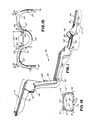
- a unitary molding for this purpose is designated by 10, and is shown in Figs. 1-4 in its unassembled state.
- the molding basically comprises three sections: a body section 11, a handle section 12, and a trigger section 13.
- the handle section lies between and connects the body and trigger sections.
- body section 11 preferably includes components forming a staple guide passage 15 (see Figs. 10 and 12), a magazine or holder 16 from which staples are fed into the staple guide passage, a feed spring 17, an anvil 18, a staple ejection spring 19, a driver guide channel 20, the pawl 21 of a driver ratchet, and two laterally spaced trigger pivot openings 22.
- the middle or hand section 12 includes the forward part 26 of a pistol grip, an intermediate flexible or bendable portion 27 which forms the butt of the grip, the rear part 28 of the grip, and latch means 29, 29a for securing the front and rear grip components together.
- the trigger section 13 of molding 10 includes components forming a trigger 33, two stub pivot axles 34, a driver 35, a driver retract spring 36, the rack 37 of the driver ratchet, a backup or supplementary feed spring 38, and connecting means 40 between the trigger and the driver for pulling driver 35 forward when trigger 33 is pulled.
- trigger section 13 is swung up and forward from the handle section so that it is above or over-lying the body.
- Driver 35 is inserted into the driver guide channel 20 in the body so that it can slide forward therein.
- the trigger is pulled forward and over the front end of body section 11, which is passed partway through a body aperture 43 in the trigger section (Fig. 2).
- the trigger section is oriented so that trigger 33 extends at an angle, preferably substantially perpendicularly, to the body.
- the trigger sides can be flexed out so that pivot axles 34, 34 can be snapped into pivot openings 22, 22 in the body.
- the rear part 28 of the grip is latched to the front part 26 by hooking grip latch portion 29 into the cooperating opening 29a (see Fig. 5).
- the handle section thereby forms a pistol grip type handle, rearwardly of the body and trigger, so that the trigger can be drawn to the grip to actuate the closure of a staple at the front end of the body section.
- This type of grip is more effective, from ergonometric considerations, than toggle-action means of the prior art which are operated between the fingertips.
- FIG. 5 show the stapler in its assembled or use configuration.
- the trigger 33 is pivoted for counterclockwise movement toward grip 48 in the direction indicated by arrow 49, (Fig. 5).
- the trigger is connected rearwardly to driver 35, at a point behind the trigger, by connecting means comprising straps 40, 40 on each side of the driver (best seen in Figure 2).
- Driver 35 slides in body 11 between upper and lower driver guide ways 50, 51 in body 11.
- the forward or tip end 53 of the driver (see Figures 14A-C) engages and pushes forward the uppermost staple 54 of a stack 55 of staples.
- Stack 55 is loaded into magazine 16 at the time the stapler is being assembled; or a separate magazine can be used.
- a visual counter or indicator can optionally be provided to show the number of staples remaining.
- the stack 55 of staples is urged upwardly in body 11 by feed spring 17, against an overhead bridge or staple retainer 56, in position to be engaged by the driver.
- Spring 17 is assisted by backup spring 38 which increases the upward force on the stack 55 of staples during closure of the staple.
- the top staple 54 when engaged by the driver, is moved forwardly from stack 55 and along staple guide passage 15 until it abuts the downwardly projecting anvil 18.
- a preferred form of staple 54 is shown enlarged in Figures 14A and 15 in its open or as-supplied configuration.
- the shape of the staple, prior to forming, is referred to herein as an "M" or “spider” shape.
- the staple has a pair of parallel, straight outer legs 59, 59 having pointed or chisel; tips 60, 60.
- the legs 59, 59 are joined to straight intermediate sections 61, 61 by outer bends or knees 62, 62.
- the intermediate sections 61, 61 extend upwardly and outwardly from a rounded, preferably semicircular, center section 64 at inner bends 65, 65 to form an obtuse central angle 66 between them.
- the obtuse angle 66 between intermediate sections 61, 61 should preferably be about 140-150°, most preferably 150°.
- the center section 64 is an arc, preferably of about 180-188°, most preferably 184°, and its preferably extended by short straight sections 72, 72, at its upper end, just inwardly of inner bends 65, 65 so that the center section is preferably somewhat U-shaped.
- the intermediate sections 61, 61 should form angles 67, 67 of about 100-110°, most preferably 105°, with the axes 63 of the extension 72, 72 of the center section (see Fig. 15).
- the outer bends preferably form acute angles 70, 70 of about 70- 75°, most preferably 75°, between the intermediate sections 61, 61 and the legs, so that the outer legs are parallel to each other.
- angles 67 and 70 of the inner and outer bends collectively they should be such that when the center section 64 is straightened in closure, the legs will be slightly inbent (about 2-5°), as shown in Fig. 16.
- the sum of the angles of an inner bend 65 and an outer bend 62 should be less than 180°, preferably about 178°.
- the staples may be made of about .02" diameter round stainless steel wire; they are usually quite small, and may, for example, be about .2" high by .4" wide in open form.
- Outer legs 59, 59 which are straight rather than curved as in the prior art, are provided to impart a better skin gathering ability, and to hold the edges of the wound more tightly together after closure.
- the staple is closed by flattening or straightening the rounded center portion 64; there should be essentially no bending at either the outer bends 62 or the inner bends 65.
- the staple In the closed configuration the staple has a pentagonal "B" shape, shown in Figures 13, 14C and 16, defined by the now straightened center 64, the two straight sections 61, 61, and the two straight legs 59, 59, which are inbent toward the section 64.
- the tips 60 are brought together and may actually overlap to a small degree, in order to provide for some possible springback after forming.
- the angle 71 between legs 59, 59 in closed configuration should be about 175-178° (see Fig. 16).
- the stapled skin flaps will slide out and apart on the staple legs 59, 59 to the outer bends 62, 62 thereof, so that the two edges of the cut abut for healing.
- the inbent shape of the staple with the skin flaps seated on the intermediate sections and the outer bends and the legs inbent toward the center part of the staple, resists rotation about an axis perpendicular to the plane of the staple.
- the pointed tips remain directly beneath center section 64, which is outside the skin; this facilitates staple removal.
- Stapler body section 11 has two spaced side flanges 73, 74, which are connected to one another at various longitudinal positions by transverse webs or bridges (Figs. 9 and 10).
- trigger 33 straddles these body flanges on the outside, and projects approximately perpendicularly to the body.
- the trigger is pivotally connected to and between opposed openings 22 in ears 75 depending from the body flanges 73 and 74.
- the anvil or staple forming post 18 depends from web 76 (Fig. 9) into the path of staple movement in staple guide passage 15, defined by and between parallel upper and lower ways 50, 51 (Fig. 10). These ways are formed on the inside surfaces of body flanges 73, 74.
- Staple ejection spring 19 is presented immediately rearwardly of anvil 18 and is a leaf spring having a tip 78 which exerts a downward bias or spring force on a staple at the anvil, urging the staple downwardly to eject it from anvil 18 (see Figs. 10, 12, and 14C) when the staple is no longer pressed against the anvil by the driver.
- Staples are supplied upwardly from below into staple guide passage 15, from the magazine or supply means 55 (see Figs 5 and 10).
- This magazine 55 has two spaced vertical ribs 79, 79, set in from the respective body flanges, and a center channel or guide 80 between them (Fig. 9).
- Guide 80 receives and guides the rounded center section 64 of the staples, while the ribs 79, 79 project between the staple legs 59, 59.
- the stapler may be made as a "low-count" unit, i.e., the supply may be sized to contain only a small number of staples. However, will be apparent that the supply means can be changed to accommodate a greater number of staples.
- the stack of staples 55 is held upwardly by a forwardly projecting cantilever leaf spring 17 which is supported at its rearward end by the two body sides 73, 74.
- the backup spring 38 projects forwardly from driver 35 (see Figs. 2 and 3), and in use applies an upward biasing force to feed spring 17, and hence to the staples.
- the supplementary spring 38 is proximate to but does not engage or exert force on feed spring 17.
- trigger 33 is pulled, forward motion of the driver brings the tip 82 of the spring into camming and biasing contact with spring 17, as shown in Fig. 7.
- spring 38 applies an increasing force to spring 17, thereby insuring the staples are held upwardly and in contact with the driver.
- the tip of spring 38 engages spring 17 between a bent knee 83 or crook thereof and the point of attachment 84 to the body, and exerts an upward force on feed spring 17.
- Pulling trigger 33 to its fully retracted position shown in Figure 1 causes the tip 82 of supplementary spring 38 to slide past knee 83, thereby shortening the effective length of the lever acting on spring 17 and increasing the biasing force on stack 55 as the trigger is progressively pulled back.
- the purpose of the staple feed spring 17 is to apply an upward pressure force on the staples at all times, after the magazine is loaded; the purpose of the backup or supplementary spring 38 is to apply increased force when the driver is "cocked” just prior to first use. This force increases as the driver engages the staple 54, and insures that the staple does not "cock” or get cammed downwardly out of the path of the driver end 53.
- the spring is not stressed until the gun is cocked immediately prior to first use, which prevents loss of force from plastic creep.
- the driver 35 is formed as part of trigger section 13, wherein it projects between the sides of the trigger.
- the driver is an elongated tongue which is guided and confined in a driver guide channel 20, defined by the guide ways 50, 51 of the body.
- Driver guide channel 20 is a rearward extension of the staple guide passage 15.
- the driver has a tip 53 which is specially configured, as best shown in Figure 14B, to exert a staple bending force which progressively increases as the staple tips 60, 60 are brought together. This is done by reducing the lever arm, and thereby increasing the force applied to the staple by the driver, as the staple is closed.
- the anvil 18 acts as the fulcrum about which the rounded center 64 of the staple is straightened; force is applied to the staple on each side of the anvil by the driver at points which move inward stepwise, toward the centerline, as the staple is closed. More specifically, driver tip 53 is doubly stepped or recessed, to present longitudinally offset staple centering and forming pockets which engage different parts of the staple as it is progressively formed in clinching.
- the driver has a pair of first or outer recesses or pockets, shown in Fig. 14A at 86, which engage the outer bends 62, 62 of staple 54.
- inner recesses 87, 87 which engage the staple inner bends 65, 65 (Fig. 14B).
- a central recess 88 is provided between and rearwardly of the inner recesses 87, 87.
- the staple When the driver advances staple 54 to the anvil, the staple is first engaged at its outer bends 62, 62, by the outer recesses 86, 86. These apply force to bend the staple, moving the staple outer bends forward while the staple center 64 is straightened on the anvil. As this occurs, the inner bends 65, 65 come into engagement with driver inner recesses or pockets 87, 87; the lever arm, i.e., the lateral distance between these pockets and anvil 18, is less than that between the anvil and the outer pockets, so that the bending force increases.
- the tips are brought together smoothly without excessive hand force being required (Figs. 1B and C). The driver tip engages and lifts staple ejection spring 19 when the staple is being closed; thereafter, when the driver is moved away from the formed staple, spring 19 is released and kicks the staple off anvil 18, as shown in Fig. 12.
- a ratchet mechanism is provided which permits reverse driver movement only after the driver has been advanced to its forwardmost position, corresponding to the ejection of the staple from the anvil.
- the ratchet mechanism is best seen in figures 5 and 6, and comprises a rack 37 carried by the driver, and a spring-loaded pawl 21 which is presented on a spring member 90 mounted by and between body side flanges 73, 74.
- the ratchet mechanism also includes a stop 91 which is spaced from the rack on the underside of driver 35.
- the unit is supplied or shipped with the ratchet in an un-stressed condition wherein the pawl is not engaged with either stop 91 or rack 37 (Fig. 5).
- trigger 33 is pulled, the driver is advanced into the body, carrying rack 37 in the direction of arrow 92 in Figure 6. This brings stop 91 into camming engagement with pawl 21.
- the pawl spring 90 is flexed, allowing pawl 21 to move to the right in Figure 6, past the stop to the dashed line "Ready” position shown in figure 6, and then into engagement with rack 37.
- the engagement of pawl 21 and rack 37 prevents reverse driver movement. This is shown by the dashed line "Must Complete" position in Figure 6.
- the ratchet rack 37 moves progressively forward past pawl 21, and the pawl seats nearer and nearer the rear of the rack.
- the pawl spring leg 90 is increasingly deflected, and when the pawl moves beyond the last seat on the rack ("End” in Figs. 6), the stress of spring 90 snaps the pawl laterally across the end of the rack to the other or flat side 93 of the rack ("Return” position shown in Fig. 6). This permits the rack to be moved rearwardly (to the right in Fig. 6) past the pawl, to disengage and reset in the ready position for the next staple.
- the stop prevents the driver from returning to the as-shipped position (see Fig. 7).
- Trigger 33 has two spaced sides 94, 95, connected by an end web 96 and defining body aperture 43 between them. These two sides flank but are spaced from driver 35 and backup spring 38.
- Two tension members, straps or yokes 40, 40 connect what in assembled state is the top part 97 of the trigger (above the axle 34 and adjacent retract spring 36) to the driver (Figs. 1 and 2). In assembled condition, the body extends through aperture 43 between trigger sides 94, 95, so that the trigger straddles the body.
- the top 97 of the trigger is arcuate or radiused about pivot axles 34, 34 to provide swingable support for the straps.
- the trigger straddles and is pivotally connected to apertures in ears, one of which is shown at 75 in Figure 5, which project below the body sides 73, 74.
- the pair of stub axles 34, 34 have arrowhead snaps 98, by which they are locked into the pivot openings 22, 22 once the trigger is positioned with respect to the body.
- the driver return spring 36 has an S-shape (Fig. 5), and extends forward from rear grip surface 28 to the driver (Fig. 5). This spring has a thin bending portion 99, and is tensioned when the trigger is pulled forward over the body. When the driver is pulled forward by the straps 40, 40, spring 36 exerts a force in the direction of arrow 100 to retract the driver and thereby return the trigger to its normal position.
Abstract
Description
- This invention relates to staplers, and in an important aspect to a low cost stapler which can be made as and assembled from a unitary one-piece molding. The stapler is useful, among other applications, for suturing incisions and wounds in the skin.
- While one-piece staplers are known, as shown in US Patent 4477008, they have been operated by squeezing the fingers together tranversely to the stapler axis. No previously known one-piece stapler has had a pistol grip by which it can be held in the palm and operated by squeezing a trigger in line with the axis of the stapler. Moreover, no known one-piece stapler has enabled the operator to apply a high degree of leverage in closing the staple. On the contrary, a relatively large force has previously been required to be applied between the finger tips, to form the staple; this made it difficult to use as light a force as is desirable in suturing a wound.
- In accordance with one aspect of the invention an elongated molding for assembly into a stapler, comprises a body section at one end, a trigger section presenting a trigger at an opposite end, and a handle section between and interconnecting the body and trigger sections, the trigger presenting a body aperture sufficiently wide for the body section to be inserted into it, the handle section including a portion which can be flexed to permit the trigger to be brought forwardly over the front end of the body section and the body section inserted into the aperture so that the trigger extends obliquely to the body section, the handle section in use forming a pistol grip by which the stapler is held.
- In accordance with another aspect of the invention, an elongated molding for assembly into a stapler, comprises a body section at one end, a trigger section presenting a trigger at an opposite end, a handle section between and interconnecting the body and trigger section, the handle section adapted to form a pistol grip by bending back on itself, and integral means for pivotally mounting the trigger angularly to the body section, in front of the grip.
- In accordance with a further aspect of the invention, a stapler comprises, a body, a trigger pivotally connected to the body, and a pistol grip, the trigger being pivoted to the body and swingable rearwardly about its pivot, toward the grip, a driver slidable in the body in a driver guide channel therein, the trigger including a top part which rotates forwardly when the trigger is pivoted toward the grip, and strap means connected between the top part of the trigger and the driver, to pull the driver in the guide channel as the trigger is pulled.
- In accordance with a yet further aspect of the invention, in combination, a staple and a stapler for forming the staple, the staple in its open configuration comprising, a rounded centre section, intermediate sections extending upwardly and outwardly from the centre section at inner bends, the intermediate sections forming an obtuse angle between them, and parallel, straight outer legs joined to the respective intermediate sections by outer bends and forming acute angles with the intermediate section, the legs terminating in pointed tips, the angulation of the inner and outer bends being sufficient that, when the staple is closed by flattening the centre section, the straight legs project toward the centre section to form a "B" shape, the stapler having an anvil for engaging the centre section of the staple, a driver movable to push the stapler against the anvil, the driver having a staple-engaging end which is of stepped shape and which engages the staple progressively closer to the centre as the staple is closed, the end having a pair of outer recesses for initially engaging the staple at the outer bends and for applying force to bring the tips toward one another as the centre section of the staple is driven against the anvil, the centre section being partly straightened thereby, the driver also having a pair of inner recesses for engaging the inner bends of the staple after the legs of the staple have been displaced angularly toward one another, to complete the closure of the staple.
- In accordance with a yet further aspect of the invention a stapler has a staple guide passage wherein staples are sequentially engaged by a driver and are formed against an anvil, a supply of staples positioned to be fed into the passage for engagement by the driver, a feed spring biasing the supply toward the passage, and a supplementary spring movable into engagement with the feed spring to supply additional force thereto when the driver is moved to engage a staple from the supply.
- Such a stapler is of a fundamentally new configuration. This configuration enables it to be made as a unitary molding, although the stapler can also be assembled from separately molded parts. Because it can be made as a single molded part, this stapler can be produced less expensively than one assembled from many separate parts.
- The stapler is of the general type wherein the staple is closed "blind" from the top, on an anvil which projects into the staple itself, as distinguished from those wherein the staple is closed on an anvil which engages the staple from the back. Staplers of this general type are useful for suturing skin, closing packages, and other blind stapling situations where an anvil cannot be placed behind the object to be stapled.
- The relatively low cose of the stapler particularly adapts it for medical use; it is sufficiently inexpensive that it can be discarded after only a single use, rather than being sterilized for re-use.
- The stapler provides a construction having a palm held hand grip and a lever trigger which provides good leverage to operate a staple former or driver to close the staple, and enables the operator to apply a soft touch in stapling. This feature is useful for medical use.
- The handle section of the molding is suitably folded or bent over itself to permit the trigger end section to be brought forwardly and down over the front end of the body section. The trigger section has an aperture which is sufficiently wide that the body section can be inserted into and partly through this aperture so that the trigger extends approximately perpendicularly to the body section. The driver extends from the trigger section and is inserted into a passage in the body as the trigger is being thus positioned. The folded-over handle portions lock together to form a pistol grip for the stapler.
- In the stapler, whether assembled from a onepiece molding or from separate parts, the driver is preferably movable in a channel in the body to engage a staple and press it forwardly in a stapler guide passage against an anvil which depends from the front end of the body. Staples are fed between the driver and the anvil, into the guide passage. The trigger is pivotally mounted and is operated by pulling it rearwardly, toward the pistol grip. The trigger includes a finger-engaging portion below its pivot and a top part above the pivot; as the finger engaging portion is pulled back toward the grip, the top part swings forward. The top part of the trigger is connected rearwardly to the driver, at a position behind the trigger, by one or more straps, to pull the driver forwardly as the trigger is pulled back.
- Staples are preferably supplied to the staple guide passage from a stack or magazine which feeds them sequentially into the passage on a right angular path from below. The staples are biased toward the guide passage by a feed spring. The open tips of the staple being applied are fully viewable by the operator; this results in part from the fact that the stapler is gripped below and rearwardly of the body, away from the staple applying tip.
- When the trigger is operated to bring the driver into engagement with the first staple from the supply, a supplementary or backup spring is moved forward with the driver and is brought into engagement with the feed spring to increase the force exerted by the feed spring. An increasing force is thereby applied to urge the staple into the guide passage as the driver moves forward; this force decreases as the driver retracts. The backup spring is preferably formed as a part of the driver and extends beneath it into position to engage the feed spring. The backup spring is not stressed during shipment or storage, or until the trigger is first pulled; this avoids the creep or cold flow which has previously hampered use of plastic springs.
- The stapler is preferably used with staples which in the open configuration are "M" or spider-shaped and which, in closed position, form what can be called a pentagonal "B" shape wherein the legs are inbent toward the center. This "B" shape is especially advantageous because it better resists rotation of the staple in the wound, so that those portions of the staple which were outside the skin at closure, remain outside thereafter. The "B" shape is also desirable because the large curves of the legs facilitate removal without tearing the skin. The staples are closed by straightening a rounded or U-shaped center section, without bending other parts of the staple. In such closure the stapler acts in a unique "soft touch" manner, by first exerting staple-closing force over a long lever arm to just the outer bends of the staple, to start to straighten the center bend, and then shortening the lever arm by moving the point of engagement by the driver closer to the center of the staple, as the outer portions of the staple legs become less accessible to the driver. In this manner the staples are closed smoothly without excessive hand force being required. In this procedure the staple cooperates with a specially configured staple-engaging end surface of the driver. Outer centering pockets of the driver first engage the staple outwardly adjacent the legs thereof; then inner pockets of the driver engage the staples closer to the center portion; this shortens the lever arm (the distance from the centerline of the staple to the point of engagement by the driver).
- The formed staple is ejected from the anvil, when the driver is retracted, by an integral staple ejection spring which bears on the staple at the anvil and presses it off the anvil.
- After the staple has been formed, the driver is retracted from its forwardmost position by a retract spring which preferably is formed as an S-shaped spring between the pistol grip and the driver. A ratchet is provided to prevent the driver from being retracted from a staple once the driver has started pushing that staple toward the anvil. This mechanism prevents interposing a second staple into the path of the driver before an earlier staple has been ejected. As with the backup spring, the ratchet spring is not stressed until the stapler is used for the first time.
- The stapler is supplied to the user in a configuration such that it is virtually ready for use but wherein the most important springs, that is, the backup spring, the driver retract spring, and the ratchet spring, are not loaded (stressed). They are loaded automatically as the trigger is first pulled. At the time of first use, the stapler is cocked by pulling the trigger to a point which brings the ratchet pawl past an initial stop, thereby loading it and preventing the trigger from returning to an uncocked position thereafter. At this point the backup spring is brought into engagement with the feed spring, and the driver is in position to engage a first staple. The unstressed condition of the springs prior to time of use provides an extended shelf life for the stapler.
- The invention will now be described by way of example, with reference to the accompanying drawings, in which:
- Figure 1 is a perspective view of a preferred form of one-piece molding prior to assembly into a stapler according to the present invention,
- Figure 2 is a top plan view of the one-piece molding shown in Figure 1,
- Figure 3 is a longitudinal vertical section of the unassembled molded piece of Figure 1, taken on line 3-3 of Figure 2,
- Figure 4 is a plan view of the underside of the molded piece of Figure 1, prior to assembly,
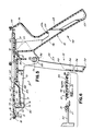
- Figure 5 is a vertical section of the assembled stapler in accordance with the present invention and in the "as-shipped" configuration, before the trigger has been pulled to advance the ratchet,
- Figure 6 is a fragmentary enlarged horizontal section of the stapler of Figure 5, as taken on line 6-6 of Figure 5, partly diagrammatic in nature, showing the relative positions of the pawl with respect to the stop and the ratchet at various stages of the operating cycle,
- Figure 7 is a longitudinal vertical section of the stapler of Figure 5 after the trigger has been pulled far enough to advance the ratchet to its initial or "cocked" position,
- Figure 8 is an enlarged transverse vertical section of the stapler of Figure 5, as taken on line 8-8 of Figure 7,
- Figure 9 is an enlarged horizontal section of the stapler of Figure 5, as taken on line 9-9 of Figure 7, with the driver omitted for clarity,
- Figure 10 is a vertical section of the stapler of Figure 5, as taken on line 10-10 of Figure 9,
- Figure 11 is a longitudinal vertical section showing the stapler of Figure 5 with the trigger fully retracted, the staple having been fully formed,
- Figure 12 is a fragmentary vertical section of the staple supply and anvil portion of the body of the stapler of Figure 5, showing the staple ejection spring kicking a staple off the anvil,
- Figure 12 is an enlarged, fragmentary horizontal section, somewhat diagrammatic, of the front end portion of the stapler of Figure 5, taken on line 13-13 of Figure 11, and shows the manner in which stapler is positioned with respect to approximated skin flaps to be stapled together,
- Figures 14A, B and C are progressive series of enlarged horizontal views of the front end of the stapler of Figure 5, showing a staple, driver, and anvil, as the staple is being formed, Figure 14A showing the staple in open configuration when it is first engaged by the driver, Figure 14B showing the staple after it has been partially formed on the anvil, and Figure 14C showing the staple in fully formed or closed configuration,
- Figure 15 is an enlarged plan view of a staple in accordance with the present invention, in the open condition, and
- Figure 16 is a plan view of the staple of Figure 15 in closed condition.
- The stapler shown in the drawings can be, and preferably is, formed as a unitary molding which incorporates, in one piece, a body, a pistol grip, a pivotable trigger, a staple driver or former, driver advance and return means, a staple holder or magazine, a staple feed spring, a backup feed spring, a driver advance ratchet, and a staple ejection spring. The drawings show the stapler as formed by a single piece molding, however, it should be understood that it can alternatively be assembled from two or more separately formed pieces. The stapler can be molded of a thermoplastic polyetherimide resin such as "Ultem 1000" or, as another example, from a polycarbonate resin such as "Lexan 124", both sold by General Electric Company. The molding process can be carried out by injection molding or other equivalent means.
- A unitary molding for this purpose is designated by 10, and is shown in Figs. 1-4 in its unassembled state. The molding basically comprises three sections: a
body section 11, ahandle section 12, and atrigger section 13. The handle section lies between and connects the body and trigger sections. As described subsequently in greater detail,body section 11 preferably includes components forming a staple guide passage 15 (see Figs. 10 and 12), a magazine orholder 16 from which staples are fed into the staple guide passage, afeed spring 17, ananvil 18, astaple ejection spring 19, adriver guide channel 20, thepawl 21 of a driver ratchet, and two laterally spacedtrigger pivot openings 22. The middle orhand section 12 includes theforward part 26 of a pistol grip, an intermediate flexible orbendable portion 27 which forms the butt of the grip, therear part 28 of the grip, and latch means 29, 29a for securing the front and rear grip components together. Thetrigger section 13 ofmolding 10 includes components forming atrigger 33, twostub pivot axles 34, adriver 35, a driver retractspring 36, therack 37 of the driver ratchet, a backup orsupplementary feed spring 38, and connectingmeans 40 between the trigger and the driver for pullingdriver 35 forward whentrigger 33 is pulled. - To assemble the one-piece molding into the stapler,
trigger section 13 is swung up and forward from the handle section so that it is above or over-lying the body.Driver 35 is inserted into thedriver guide channel 20 in the body so that it can slide forward therein. The trigger is pulled forward and over the front end ofbody section 11, which is passed partway through abody aperture 43 in the trigger section (Fig. 2). The trigger section is oriented so thattrigger 33 extends at an angle, preferably substantially perpendicularly, to the body. The trigger sides can be flexed out so thatpivot axles pivot openings rear part 28 of the grip is latched to thefront part 26 by hookinggrip latch portion 29 into the cooperatingopening 29a (see Fig. 5). The handle section thereby forms a pistol grip type handle, rearwardly of the body and trigger, so that the trigger can be drawn to the grip to actuate the closure of a staple at the front end of the body section. This type of grip is more effective, from ergonometric considerations, than toggle-action means of the prior art which are operated between the fingertips. - The various components of the stapler can best be further understood by reference to Figures 5 and following, which show the stapler in its assembled or use configuration. In the assembled stapler the
trigger 33 is pivoted for counterclockwise movement towardgrip 48 in the direction indicated byarrow 49, (Fig. 5). The trigger is connected rearwardly todriver 35, at a point behind the trigger, by connectingmeans comprising straps Driver 35 slides inbody 11 between upper and lowerdriver guide ways body 11. The forward or tipend 53 of the driver (see Figures 14A-C) engages and pushes forward theuppermost staple 54 of astack 55 of staples.Stack 55 is loaded intomagazine 16 at the time the stapler is being assembled; or a separate magazine can be used. A visual counter or indicator can optionally be provided to show the number of staples remaining. Thestack 55 of staples is urged upwardly inbody 11 byfeed spring 17, against an overhead bridge orstaple retainer 56, in position to be engaged by the driver.Spring 17 is assisted bybackup spring 38 which increases the upward force on thestack 55 of staples during closure of the staple. Thetop staple 54, when engaged by the driver, is moved forwardly fromstack 55 and alongstaple guide passage 15 until it abuts the downwardly projectinganvil 18. - A preferred form of
staple 54 is shown enlarged in Figures 14A and 15 in its open or as-supplied configuration. The shape of the staple, prior to forming, is referred to herein as an "M" or "spider" shape. The staple has a pair of parallel, straightouter legs tips legs intermediate sections knees intermediate sections center section 64 atinner bends central angle 66 between them. Theobtuse angle 66 betweenintermediate sections center section 64 is an arc, preferably of about 180-188°, most preferably 184°, and its preferably extended by shortstraight sections inner bends intermediate sections axes 63 of theextension acute angles intermediate sections angles center section 64 is straightened in closure, the legs will be slightly inbent (about 2-5°), as shown in Fig. 16. For this reason, the sum of the angles of aninner bend 65 and anouter bend 62 should be less than 180°, preferably about 178°. The staples may be made of about .02" diameter round stainless steel wire; they are usually quite small, and may, for example, be about .2" high by .4" wide in open form. - Keeping in mind the previously described configuration of the open or unformed staple, the manner in which the staple is closed to hold skin flaps together over a wound can be understood by reference to Figures 13, 14A, B, and C. Skin layers 68, 68, on either side of a wound or incision are first proximated, i.e., they are manually held together in facial engagement, as shown in Figure 13. The tip of the stapler body is notched or recessed, as at 69, so that the overlapped skin flaps can be positioned between the pointed ends 60, 60 of the staple where they can be viewed by the operator.
-
Outer legs - The staple is closed by flattening or straightening the
rounded center portion 64; there should be essentially no bending at either the outer bends 62 or the inner bends 65. In the closed configuration the staple has a pentagonal "B" shape, shown in Figures 13, 14C and 16, defined by the now straightenedcenter 64, the twostraight sections straight legs section 64. Thetips 60 are brought together and may actually overlap to a small degree, in order to provide for some possible springback after forming. The angle 71 betweenlegs staple legs center section 64, which is outside the skin; this facilitates staple removal. - Given this general description, the parts of the stapler are next discussed in further detail.
Stapler body section 11 has two spacedside flanges opposed openings 22 inears 75 depending from thebody flanges - The anvil or
staple forming post 18 depends from web 76 (Fig. 9) into the path of staple movement instaple guide passage 15, defined by and between parallel upper andlower ways 50, 51 (Fig. 10). These ways are formed on the inside surfaces ofbody flanges Staple ejection spring 19 is presented immediately rearwardly ofanvil 18 and is a leaf spring having atip 78 which exerts a downward bias or spring force on a staple at the anvil, urging the staple downwardly to eject it from anvil 18 (see Figs. 10, 12, and 14C) when the staple is no longer pressed against the anvil by the driver. - Staples are supplied upwardly from below into
staple guide passage 15, from the magazine or supply means 55 (see Figs 5 and 10). Thismagazine 55 has two spacedvertical ribs Guide 80 receives and guides therounded center section 64 of the staples, while theribs staple legs - The stack of
staples 55 is held upwardly by a forwardly projectingcantilever leaf spring 17 which is supported at its rearward end by the twobody sides backup spring 38 projects forwardly from driver 35 (see Figs. 2 and 3), and in use applies an upward biasing force to feedspring 17, and hence to the staples. When the unit is in the as-shipped condition, as shown in Figure 5, prior to initial cocking, thesupplementary spring 38 is proximate to but does not engage or exert force onfeed spring 17. Astrigger 33 is pulled, forward motion of the driver brings thetip 82 of the spring into camming and biasing contact withspring 17, as shown in Fig. 7. As the trigger is pulled further,spring 38 applies an increasing force tospring 17, thereby insuring the staples are held upwardly and in contact with the driver. The tip ofspring 38 engagesspring 17 between abent knee 83 or crook thereof and the point ofattachment 84 to the body, and exerts an upward force onfeed spring 17. - Pulling
trigger 33 to its fully retracted position shown in Figure 1 causes thetip 82 ofsupplementary spring 38 to slide pastknee 83, thereby shortening the effective length of the lever acting onspring 17 and increasing the biasing force onstack 55 as the trigger is progressively pulled back. The purpose of thestaple feed spring 17 is to apply an upward pressure force on the staples at all times, after the magazine is loaded; the purpose of the backup orsupplementary spring 38 is to apply increased force when the driver is "cocked" just prior to first use. This force increases as the driver engages the staple 54, and insures that the staple does not "cock" or get cammed downwardly out of the path of thedriver end 53. As will be seen, the spring is not stressed until the gun is cocked immediately prior to first use, which prevents loss of force from plastic creep. - The
driver 35 is formed as part oftrigger section 13, wherein it projects between the sides of the trigger. The driver is an elongated tongue which is guided and confined in adriver guide channel 20, defined by theguide ways Driver guide channel 20 is a rearward extension of thestaple guide passage 15. The driver has atip 53 which is specially configured, as best shown in Figure 14B, to exert a staple bending force which progressively increases as thestaple tips anvil 18 acts as the fulcrum about which the roundedcenter 64 of the staple is straightened; force is applied to the staple on each side of the anvil by the driver at points which move inward stepwise, toward the centerline, as the staple is closed. More specifically,driver tip 53 is doubly stepped or recessed, to present longitudinally offset staple centering and forming pockets which engage different parts of the staple as it is progressively formed in clinching. The driver has a pair of first or outer recesses or pockets, shown in Fig. 14A at 86, which engage the outer bends 62, 62 ofstaple 54. Rearwardly and inwardly of theouter recess sections inner recesses central recess 88 is provided between and rearwardly of theinner recesses - When the driver advances staple 54 to the anvil, the staple is first engaged at its
outer bends outer recesses staple center 64 is straightened on the anvil. As this occurs, the inner bends 65, 65 come into engagement with driver inner recesses orpockets anvil 18, is less than that between the anvil and the outer pockets, so that the bending force increases. The tips are brought together smoothly without excessive hand force being required (Figs. 1B and C). The driver tip engages and liftsstaple ejection spring 19 when the staple is being closed; thereafter, when the driver is moved away from the formed staple,spring 19 is released and kicks the staple offanvil 18, as shown in Fig. 12. - It is important that once a staple has been picked up from the magazine and the forming operation has begun, the driver should not be withdrawn or moved back from the staple. If the driver were moved back and thereafter advanced, a second staple could be picked up in the
staple guide passage 15 before the first staple was ejected, and jamming could result. In order to prevent the driver from being withdrawn after it has once been moved forward into contact with a given staple, a ratchet mechanism is provided which permits reverse driver movement only after the driver has been advanced to its forwardmost position, corresponding to the ejection of the staple from the anvil. The ratchet mechanism is best seen in figures 5 and 6, and comprises arack 37 carried by the driver, and a spring-loadedpawl 21 which is presented on aspring member 90 mounted by and betweenbody side flanges stop 91 which is spaced from the rack on the underside ofdriver 35. The unit is supplied or shipped with the ratchet in an un-stressed condition wherein the pawl is not engaged with either stop 91 or rack 37 (Fig. 5). Astrigger 33 is pulled, the driver is advanced into the body, carryingrack 37 in the direction ofarrow 92 in Figure 6. This brings stop 91 into camming engagement withpawl 21. Thepawl spring 90 is flexed, allowingpawl 21 to move to the right in Figure 6, past the stop to the dashed line "Ready" position shown in figure 6, and then into engagement withrack 37. The engagement ofpawl 21 andrack 37 prevents reverse driver movement. This is shown by the dashed line "Must Complete" position in Figure 6. - As the driver is advanced, the
ratchet rack 37 moves progressively forward past pawl 21, and the pawl seats nearer and nearer the rear of the rack. Thepawl spring leg 90 is increasingly deflected, and when the pawl moves beyond the last seat on the rack ("End" in Figs. 6), the stress ofspring 90 snaps the pawl laterally across the end of the rack to the other orflat side 93 of the rack ("Return" position shown in Fig. 6). This permits the rack to be moved rearwardly (to the right in Fig. 6) past the pawl, to disengage and reset in the ready position for the next staple. - Once the pawl has been moved past
stop 91 during the first cycle of operation, the stop prevents the driver from returning to the as-shipped position (see Fig. 7). - The driver, as well as
rack 37, stop 91, andbackup spring 38, are advanced into the body by pullingtrigger 33 towardgrip 48.Trigger 33 has two spacedsides end web 96 and definingbody aperture 43 between them. These two sides flank but are spaced fromdriver 35 andbackup spring 38. Two tension members, straps or yokes 40, 40, connect what in assembled state is thetop part 97 of the trigger (above theaxle 34 and adjacent retract spring 36) to the driver (Figs. 1 and 2). In assembled condition, the body extends throughaperture 43 between trigger sides 94, 95, so that the trigger straddles the body. As the trigger is pulled, itstop part 97 rotates forwardly above thepivots straps pivot axles - The trigger straddles and is pivotally connected to apertures in ears, one of which is shown at 75 in Figure 5, which project below the body sides 73, 74. For this purpose, the pair of
stub axles pivot openings - The
driver return spring 36 has an S-shape (Fig. 5), and extends forward fromrear grip surface 28 to the driver (Fig. 5). This spring has athin bending portion 99, and is tensioned when the trigger is pulled forward over the body. When the driver is pulled forward by thestraps spring 36 exerts a force in the direction ofarrow 100 to retract the driver and thereby return the trigger to its normal position.
Claims (28)
Priority Applications (1)
| Application Number | Priority Date | Filing Date | Title |
|---|---|---|---|
| AT86307991T ATE65374T1 (en) | 1985-11-01 | 1986-10-15 | SINGLE USE STAPLER. |
Applications Claiming Priority (2)
| Application Number | Priority Date | Filing Date | Title |
|---|---|---|---|
| US06/793,955 US4648542A (en) | 1985-11-01 | 1985-11-01 | Disposable stapler |
| US793955 | 1985-11-01 |
Publications (3)
| Publication Number | Publication Date |
|---|---|
| EP0229453A2 true EP0229453A2 (en) | 1987-07-22 |
| EP0229453A3 EP0229453A3 (en) | 1987-09-30 |
| EP0229453B1 EP0229453B1 (en) | 1991-07-24 |
Family
ID=25161250
Family Applications (1)
| Application Number | Title | Priority Date | Filing Date |
|---|---|---|---|
| EP86307991A Expired - Lifetime EP0229453B1 (en) | 1985-11-01 | 1986-10-15 | Disposable stapler |
Country Status (12)
| Country | Link |
|---|---|
| US (1) | US4648542A (en) |
| EP (1) | EP0229453B1 (en) |
| JP (1) | JPS62112543A (en) |
| KR (1) | KR900002917B1 (en) |
| CN (1) | CN1008968B (en) |
| AT (1) | ATE65374T1 (en) |
| AU (2) | AU581349B2 (en) |
| BR (1) | BR8605399A (en) |
| CA (1) | CA1276401C (en) |
| DE (1) | DE3680501D1 (en) |
| MX (1) | MX164517B (en) |
| ZA (1) | ZA867583B (en) |
Cited By (6)
| Publication number | Priority date | Publication date | Assignee | Title |
|---|---|---|---|---|
| EP0253629A1 (en) * | 1986-07-14 | 1988-01-20 | Minnesota Mining And Manufacturing Company | Staple |
| EP0324166A2 (en) * | 1987-12-28 | 1989-07-19 | Edward Weck Incorporated | Method and apparatus for storing dispensing and applying surgical staples |
| US4874122A (en) * | 1986-07-14 | 1989-10-17 | Minnesota Mining And Manufacturing Company | Bent back box staple and staple closing mechanism with split actuator |
| GB2235644A (en) * | 1989-08-31 | 1991-03-13 | James Taylor | Improvements in surgical stapling devices |
| EP0442482A2 (en) * | 1990-02-13 | 1991-08-21 | Ethicon, Inc. | Rotating head skin stapler |
| WO1997039688A2 (en) * | 1996-04-22 | 1997-10-30 | Vnus Medical Technologies, Inc. | Method and apparatus for delivery of an appliance in a vessel |
Families Citing this family (38)
| Publication number | Priority date | Publication date | Assignee | Title |
|---|---|---|---|---|
| US4648542A (en) * | 1985-11-01 | 1987-03-10 | Senmed, Inc. | Disposable stapler |
| FR2622429A1 (en) * | 1987-11-16 | 1989-05-05 | Blagoveschensky G | SURGICAL SUTURE APPARATUS |
| US5161725A (en) * | 1990-02-13 | 1992-11-10 | Ethicon, Inc. | Rotating head skin stapler |
| US5240164A (en) * | 1990-02-13 | 1993-08-31 | Ethicon, Inc. | Rotating head skin stapler |
| FR2752720A1 (en) * | 1996-09-03 | 1998-03-06 | Medinov Amp | SURGICAL STAPLE SUPPORT OF THE ELASTIC, SUPERELASTIC OR SHAPE MEMORY TYPE |
| US5908149A (en) * | 1997-03-12 | 1999-06-01 | Ethicon Endo-Surgery, Inc. | Skin stapler with multi-directional release mechanism |
| US5938101A (en) * | 1997-05-14 | 1999-08-17 | Ethicon Endo-Surgery, Inc. | Skin stapler with movable anvil |
| US5937951A (en) * | 1997-07-18 | 1999-08-17 | Ethicon Endo-Surgery, Inc. | Skin stapler with rack and pinion staple feed mechanism |
| US7334717B2 (en) | 2001-10-05 | 2008-02-26 | Tyco Healthcare Group Lp | Surgical fastener applying apparatus |
| JP4245480B2 (en) * | 2001-10-05 | 2009-03-25 | タイコ ヘルスケア グループ エルピー | Surgical stapling apparatus and method |
| CA2485107C (en) * | 2002-05-10 | 2011-07-12 | Tyco Healthcare Group Lp | Surgical stapling apparatus having a wound closure material applicator assembly |
| US7296722B2 (en) | 2003-10-17 | 2007-11-20 | Tyco Healthcare Group Lp | Surgical fastener applying apparatus with controlled beam deflection |
| US7942304B2 (en) * | 2007-10-19 | 2011-05-17 | Tyco Healthcare Group Lp | Two piece anvil for surgical stapler |
| US8453905B2 (en) | 2009-01-26 | 2013-06-04 | Ethicon Endo-Surgery, Inc. | Surgical fastener for applying a large staple through a small delivery port |
| US20100187285A1 (en) * | 2009-01-26 | 2010-07-29 | Harris Jason L | Surgical stapler for applying a large staple though a small delivery port and a method of using the stapler to secure a tissue fold |
| US9713471B2 (en) | 2009-01-26 | 2017-07-25 | Ethicon Endo-Surgery, Inc. | Surgical device with tandem fasteners |
| US8801732B2 (en) * | 2009-01-26 | 2014-08-12 | Ethicon Endo-Surgery, Inc. | Surgical stapler to secure a tissue fold |
| US9713468B2 (en) * | 2009-01-26 | 2017-07-25 | Ethicon Endo-Surgery, Inc. | Surgical stapler for applying a large staple through a small delivery port and a method of using the stapler to secure a tissue fold |
| US20100191262A1 (en) * | 2009-01-26 | 2010-07-29 | Harris Jason L | Surgical stapler for applying a large staple through small delivery port and a method of using the stapler to secure a tissue fold |
| US8439244B2 (en) * | 2010-01-20 | 2013-05-14 | Ethicon Endo-Surgery, Inc. | Surgical stapler fastening device with movable anvil |
| US8602286B2 (en) * | 2009-01-26 | 2013-12-10 | Ethicon Endo-Surgery, Inc. | Apparatus for feeding staples in a low profile surgical stapler |
| US20100187283A1 (en) * | 2009-01-26 | 2010-07-29 | Lawrence Crainich | Method For Feeding Staples In a Low Profile Surgical Stapler |
| US8469252B2 (en) | 2009-01-26 | 2013-06-25 | Ethicon Endo-Surgery, Inc. | Surgical stapler fastening device with adjustable anvil |
| AU2010241934B2 (en) * | 2009-04-30 | 2014-01-16 | Cook Medical Technologies Llc | System and method for fiducial deployment |
| DE102011001706A1 (en) | 2011-03-31 | 2012-10-04 | Aesculap Ag | Surgical clip applicator |
| AU2012202752A1 (en) * | 2011-06-21 | 2013-01-17 | Ethicon Endo-Surgery, Inc. | A surgical fastener having a safety feature |
| US8838208B2 (en) | 2011-06-28 | 2014-09-16 | Cook Medical Technologies Llc | Fiducial deployment needle system |
| US8992547B2 (en) | 2012-03-21 | 2015-03-31 | Ethicon Endo-Surgery, Inc. | Methods and devices for creating tissue plications |
| US9265501B2 (en) | 2012-09-06 | 2016-02-23 | Sabic Global Technologies B.V. | Surgical stapler with corrugated thermoplastic leaf spring |
| US9522264B2 (en) | 2013-02-26 | 2016-12-20 | Cook Medical Technologies Llc | Ratchet-slide handle and system for fiducial deployment |
| CN106794018B (en) | 2013-11-04 | 2019-12-10 | 快克灵医疗技术有限公司 | Surgical suture device |
| US9770262B2 (en) | 2014-06-09 | 2017-09-26 | Cook Medical Technologies Llc | Screw-driven handles and systems for fiducial deployment |
| EP3154458B1 (en) | 2014-06-16 | 2018-08-29 | Cook Medical Technologies LLC | Plunger-driven collet handle for fiducial deployment |
| WO2016089667A1 (en) | 2014-12-03 | 2016-06-09 | Cook Medical Technologies Llc | Endoscopic ultrasound fiducial needle stylet handle assembly |
| CN104921792A (en) * | 2015-06-12 | 2015-09-23 | 季欣然 | Bone pinning device for fracture fixation |
| US10675108B2 (en) * | 2018-02-06 | 2020-06-09 | Ethicon Llc | Surgical clip applier with clip forming system |
| CN109875628B (en) * | 2019-02-26 | 2024-03-08 | 宁波市爱达维电器有限公司 | Nail box structure of medical stitching instrument |
| CN109875627B (en) * | 2019-02-26 | 2024-03-08 | 宁波市爱达维电器有限公司 | Medical long kiss type suture device |
Citations (2)
| Publication number | Priority date | Publication date | Assignee | Title |
|---|---|---|---|---|
| FR2154047A5 (en) * | 1971-09-17 | 1973-05-04 | Ici Ltd | |
| EP0074744A2 (en) * | 1981-09-03 | 1983-03-23 | Minnesota Mining And Manufacturing Company | Stapler |
Family Cites Families (22)
| Publication number | Priority date | Publication date | Assignee | Title |
|---|---|---|---|---|
| US1910688A (en) * | 1931-08-03 | 1933-05-23 | Bella Goodstein | Staple |
| DE618955C (en) * | 1932-11-12 | 1935-09-19 | Feodor Hoernlimann Dipl Ing | Equipment for the production of Ortpfählen with foldable jacket |
| US1945377A (en) * | 1933-10-25 | 1934-01-30 | Charles B Goodstein | Stapling machine |
| US3275211A (en) * | 1965-05-10 | 1966-09-27 | United States Surgical Corp | Surgical stapler with replaceable cartridge |
| US3583622A (en) * | 1969-03-21 | 1971-06-08 | Robert Frank Graeff | Stapler |
| US3827277A (en) * | 1969-07-29 | 1974-08-06 | Ici Ltd | Applicator for surgical clips |
| GB1427397A (en) * | 1973-04-24 | 1976-03-10 | Ici Ltd | Forceps |
| US3873016A (en) * | 1973-11-30 | 1975-03-25 | Meyer Fishbein | Pliers type surgical stapler for joining disunited skin or fascia |
| US4014492A (en) * | 1975-06-11 | 1977-03-29 | Senco Products, Inc. | Surgical staple |
| US4127227A (en) * | 1976-10-08 | 1978-11-28 | United States Surgical Corporation | Wide fascia staple cartridge |
| US4185762A (en) * | 1978-03-27 | 1980-01-29 | Minnesota Mining And Manufacturing Company | Medical stapling device |
| US4321002A (en) * | 1978-03-27 | 1982-03-23 | Minnesota Mining And Manufacturing Company | Medical stapling device |
| US4256251A (en) * | 1978-04-24 | 1981-03-17 | Lawrence M. Smith | Surgical staplers and staple |
| US4202480A (en) * | 1979-02-26 | 1980-05-13 | Minnesota Mining And Manufacturing Company | Stapler including means for preventing double feeding of staples |
| US4477007A (en) * | 1979-02-26 | 1984-10-16 | Minnesota Mining And Manufacturing Company | Stapler with intermediate latching mechanism |
| US4399810A (en) * | 1979-11-28 | 1983-08-23 | Samuels Peter B | Skin clip and applier |
| US4645111A (en) * | 1981-07-08 | 1987-02-24 | Howmedica, Inc. | Surgical stapler with retractable anvil |
| US4477008A (en) * | 1981-09-03 | 1984-10-16 | Minnesota Mining And Manufacturing Company | Stapler |
| DE3204532C2 (en) * | 1982-02-10 | 1983-12-08 | B. Braun Melsungen Ag, 3508 Melsungen | Surgical skin staple |
| US4523707A (en) * | 1982-05-04 | 1985-06-18 | Blake Joseph W Iii | Surgical stapler |
| US4527725A (en) * | 1982-11-04 | 1985-07-09 | Minnesota Mining And Manufacturing Company | Stapler with retractable anvil |
| US4648542A (en) * | 1985-11-01 | 1987-03-10 | Senmed, Inc. | Disposable stapler |
-
1985
- 1985-11-01 US US06/793,955 patent/US4648542A/en not_active Expired - Lifetime
-
1986
- 1986-10-03 ZA ZA867583A patent/ZA867583B/en unknown
- 1986-10-15 DE DE8686307991T patent/DE3680501D1/en not_active Expired - Lifetime
- 1986-10-15 EP EP86307991A patent/EP0229453B1/en not_active Expired - Lifetime
- 1986-10-15 AT AT86307991T patent/ATE65374T1/en not_active IP Right Cessation
- 1986-10-16 CA CA000520619A patent/CA1276401C/en not_active Expired - Lifetime
- 1986-10-27 MX MX4167A patent/MX164517B/en unknown
- 1986-10-31 BR BR8605399A patent/BR8605399A/en not_active IP Right Cessation
- 1986-10-31 JP JP61260553A patent/JPS62112543A/en active Pending
- 1986-10-31 CN CN86106345A patent/CN1008968B/en not_active Expired
- 1986-10-31 AU AU64574/86A patent/AU581349B2/en not_active Ceased
- 1986-11-01 KR KR1019860009218A patent/KR900002917B1/en not_active IP Right Cessation
-
1988
- 1988-12-19 AU AU27040/88A patent/AU596036B2/en not_active Ceased
Patent Citations (2)
| Publication number | Priority date | Publication date | Assignee | Title |
|---|---|---|---|---|
| FR2154047A5 (en) * | 1971-09-17 | 1973-05-04 | Ici Ltd | |
| EP0074744A2 (en) * | 1981-09-03 | 1983-03-23 | Minnesota Mining And Manufacturing Company | Stapler |
Cited By (12)
| Publication number | Priority date | Publication date | Assignee | Title |
|---|---|---|---|---|
| EP0253629A1 (en) * | 1986-07-14 | 1988-01-20 | Minnesota Mining And Manufacturing Company | Staple |
| US4874122A (en) * | 1986-07-14 | 1989-10-17 | Minnesota Mining And Manufacturing Company | Bent back box staple and staple closing mechanism with split actuator |
| EP0497389A2 (en) * | 1986-07-14 | 1992-08-05 | Minnesota Mining And Manufacturing Company | Staple closing mechanism with split actuator |
| EP0497389A3 (en) * | 1986-07-14 | 1993-02-24 | Minnesota Mining And Manufacturing Company | Staple closing mechanism with split actuator |
| EP0324166A2 (en) * | 1987-12-28 | 1989-07-19 | Edward Weck Incorporated | Method and apparatus for storing dispensing and applying surgical staples |
| EP0324166A3 (en) * | 1987-12-28 | 1989-12-13 | Edward Weck Incorporated | Method and apparatus for storing dispensing and applying surgical staples |
| GB2235644A (en) * | 1989-08-31 | 1991-03-13 | James Taylor | Improvements in surgical stapling devices |
| EP0442482A2 (en) * | 1990-02-13 | 1991-08-21 | Ethicon, Inc. | Rotating head skin stapler |
| EP0442482A3 (en) * | 1990-02-13 | 1991-11-06 | Ethicon Inc. | Rotating head skin stapler |
| WO1997039688A2 (en) * | 1996-04-22 | 1997-10-30 | Vnus Medical Technologies, Inc. | Method and apparatus for delivery of an appliance in a vessel |
| WO1997039688A3 (en) * | 1996-04-22 | 1998-01-29 | Vnus Med Tech Inc | Method and apparatus for delivery of an appliance in a vessel |
| US6149660A (en) * | 1996-04-22 | 2000-11-21 | Vnus Medical Technologies, Inc. | Method and apparatus for delivery of an appliance in a vessel |
Also Published As
| Publication number | Publication date |
|---|---|
| CA1276401C (en) | 1990-11-20 |
| ATE65374T1 (en) | 1991-08-15 |
| KR870004793A (en) | 1987-06-01 |
| AU6457486A (en) | 1987-05-07 |
| DE3680501D1 (en) | 1991-08-29 |
| BR8605399A (en) | 1987-08-11 |
| CN1008968B (en) | 1990-08-01 |
| EP0229453B1 (en) | 1991-07-24 |
| MX164517B (en) | 1992-08-24 |
| KR900002917B1 (en) | 1990-05-03 |
| ZA867583B (en) | 1988-05-25 |
| US4648542A (en) | 1987-03-10 |
| JPS62112543A (en) | 1987-05-23 |
| CN86106345A (en) | 1987-07-01 |
| AU2704088A (en) | 1989-04-13 |
| EP0229453A3 (en) | 1987-09-30 |
| AU596036B2 (en) | 1990-04-12 |
| AU581349B2 (en) | 1989-02-16 |
Similar Documents
| Publication | Publication Date | Title |
|---|---|---|
| EP0229453B1 (en) | Disposable stapler | |
| US4519532A (en) | Stapler including ratchet means for preventing double feeding of staples | |
| CA1193165A (en) | Multiple clip applier | |
| US4470532A (en) | Medical stapling device | |
| JPS6236694B2 (en) | ||
| US5062563A (en) | Fascia stapler | |
| US3873016A (en) | Pliers type surgical stapler for joining disunited skin or fascia | |
| CN102647948B (en) | Improved clip advancer | |
| EP0089737B1 (en) | Ligating clip cartridge | |
| US4480641A (en) | Tip configuration for a ligating clip applier | |
| EP1805849B1 (en) | Apparatus for applying surgical clips | |
| CA1193937A (en) | Surgical stapler | |
| JP2656826B2 (en) | Surgical stapler | |
| US4493322A (en) | Surgical stapling instrument | |
| EP0588081A2 (en) | Surgical fastening device | |
| JPS62243545A (en) | Stapler for operation | |
| WO1979000970A1 (en) | Improved surgical staplers and staple | |
| JPH012640A (en) | Hemostatic forceps applicator for attaching multiple hemostatic forceps | |
| JPH0463696B2 (en) | ||
| US4527725A (en) | Stapler with retractable anvil | |
| US4477007A (en) | Stapler with intermediate latching mechanism | |
| JPS60207656A (en) | Surgical stapler | |
| JPS6138692B2 (en) | ||
| JPS60500705A (en) | Safety device for surgical occlusion cutting device |
Legal Events
| Date | Code | Title | Description |
|---|---|---|---|
| PUAI | Public reference made under article 153(3) epc to a published international application that has entered the european phase |
Free format text: ORIGINAL CODE: 0009012 |
|
| AK | Designated contracting states |
Kind code of ref document: A2 Designated state(s): AT BE CH DE ES FR GB IT LI NL SE |
|
| PUAL | Search report despatched |
Free format text: ORIGINAL CODE: 0009013 |
|
| AK | Designated contracting states |
Kind code of ref document: A3 Designated state(s): AT BE CH DE ES FR GB IT LI NL SE |
|
| 17P | Request for examination filed |
Effective date: 19870819 |
|
| 17Q | First examination report despatched |
Effective date: 19890904 |
|
| GRAA | (expected) grant |
Free format text: ORIGINAL CODE: 0009210 |
|
| AK | Designated contracting states |
Kind code of ref document: B1 Designated state(s): AT BE CH DE ES FR GB IT LI NL SE |
|
| PG25 | Lapsed in a contracting state [announced via postgrant information from national office to epo] |
Ref country code: SE Effective date: 19910724 Ref country code: NL Effective date: 19910724 |
|
| REF | Corresponds to: |
Ref document number: 65374 Country of ref document: AT Date of ref document: 19910815 Kind code of ref document: T |
|
| ITF | It: translation for a ep patent filed |
Owner name: MODIANO & ASSOCIATI S.R.L. |
|
| REF | Corresponds to: |
Ref document number: 3680501 Country of ref document: DE Date of ref document: 19910829 |
|
| ET | Fr: translation filed | ||
| PG25 | Lapsed in a contracting state [announced via postgrant information from national office to epo] |
Ref country code: ES Free format text: LAPSE BECAUSE OF FAILURE TO SUBMIT A TRANSLATION OF THE DESCRIPTION OR TO PAY THE FEE WITHIN THE PRESCRIBED TIME-LIMIT Effective date: 19911104 |
|
| NLV1 | Nl: lapsed or annulled due to failure to fulfill the requirements of art. 29p and 29m of the patents act | ||
| PLBE | No opposition filed within time limit |
Free format text: ORIGINAL CODE: 0009261 |
|
| STAA | Information on the status of an ep patent application or granted ep patent |
Free format text: STATUS: NO OPPOSITION FILED WITHIN TIME LIMIT |
|
| 26N | No opposition filed | ||
| REG | Reference to a national code |
Ref country code: GB Ref legal event code: IF02 |
|
| PGFP | Annual fee paid to national office [announced via postgrant information from national office to epo] |
Ref country code: FR Payment date: 20051010 Year of fee payment: 20 |
|
| PGFP | Annual fee paid to national office [announced via postgrant information from national office to epo] |
Ref country code: GB Payment date: 20051012 Year of fee payment: 20 Ref country code: AT Payment date: 20051012 Year of fee payment: 20 |
|
| PGFP | Annual fee paid to national office [announced via postgrant information from national office to epo] |
Ref country code: CH Payment date: 20051014 Year of fee payment: 20 Ref country code: DE Payment date: 20051014 Year of fee payment: 20 |
|
| PGFP | Annual fee paid to national office [announced via postgrant information from national office to epo] |
Ref country code: IT Payment date: 20051027 Year of fee payment: 20 |
|
| REG | Reference to a national code |
Ref country code: GB Ref legal event code: PE20 |
|
| PGFP | Annual fee paid to national office [announced via postgrant information from national office to epo] |
Ref country code: BE Payment date: 20051215 Year of fee payment: 20 |
|
| PG25 | Lapsed in a contracting state [announced via postgrant information from national office to epo] |
Ref country code: GB Free format text: LAPSE BECAUSE OF EXPIRATION OF PROTECTION Effective date: 20061014 |
|
| REG | Reference to a national code |
Ref country code: CH Ref legal event code: PL |
|
| BE20 | Be: patent expired |
Owner name: *SENMED INC. Effective date: 20061015 |