EP0229399A2 - Arrangement for wireless signal transmission from a rotating body - Google Patents
Arrangement for wireless signal transmission from a rotating body Download PDFInfo
- Publication number
- EP0229399A2 EP0229399A2 EP86118165A EP86118165A EP0229399A2 EP 0229399 A2 EP0229399 A2 EP 0229399A2 EP 86118165 A EP86118165 A EP 86118165A EP 86118165 A EP86118165 A EP 86118165A EP 0229399 A2 EP0229399 A2 EP 0229399A2
- Authority
- EP
- European Patent Office
- Prior art keywords
- transmitter
- rotating body
- receiver
- housing
- unit
- Prior art date
- Legal status (The legal status is an assumption and is not a legal conclusion. Google has not performed a legal analysis and makes no representation as to the accuracy of the status listed.)
- Granted
Links
- 230000008054 signal transmission Effects 0.000 title claims description 3
- 238000012545 processing Methods 0.000 claims abstract description 16
- 238000006243 chemical reaction Methods 0.000 claims description 4
- 230000002093 peripheral effect Effects 0.000 claims 1
- 238000002485 combustion reaction Methods 0.000 description 4
- 238000013461 design Methods 0.000 description 2
- 238000005553 drilling Methods 0.000 description 2
- 230000005540 biological transmission Effects 0.000 description 1
- 238000004891 communication Methods 0.000 description 1
- 238000005520 cutting process Methods 0.000 description 1
- 238000011161 development Methods 0.000 description 1
- 238000011156 evaluation Methods 0.000 description 1
- 230000007717 exclusion Effects 0.000 description 1
- 230000001939 inductive effect Effects 0.000 description 1
- 238000005461 lubrication Methods 0.000 description 1
- 238000003754 machining Methods 0.000 description 1
- 238000005259 measurement Methods 0.000 description 1
- 238000003801 milling Methods 0.000 description 1
- 238000012806 monitoring device Methods 0.000 description 1
- 238000012544 monitoring process Methods 0.000 description 1
- 230000010355 oscillation Effects 0.000 description 1
- 230000002028 premature Effects 0.000 description 1
- 238000003860 storage Methods 0.000 description 1
Images


Classifications
-
- B—PERFORMING OPERATIONS; TRANSPORTING
- B23—MACHINE TOOLS; METAL-WORKING NOT OTHERWISE PROVIDED FOR
- B23Q—DETAILS, COMPONENTS, OR ACCESSORIES FOR MACHINE TOOLS, e.g. ARRANGEMENTS FOR COPYING OR CONTROLLING; MACHINE TOOLS IN GENERAL CHARACTERISED BY THE CONSTRUCTION OF PARTICULAR DETAILS OR COMPONENTS; COMBINATIONS OR ASSOCIATIONS OF METAL-WORKING MACHINES, NOT DIRECTED TO A PARTICULAR RESULT
- B23Q1/00—Members which are comprised in the general build-up of a form of machine, particularly relatively large fixed members
- B23Q1/0009—Energy-transferring means or control lines for movable machine parts; Control panels or boxes; Control parts
-
- B—PERFORMING OPERATIONS; TRANSPORTING
- B23—MACHINE TOOLS; METAL-WORKING NOT OTHERWISE PROVIDED FOR
- B23B—TURNING; BORING
- B23B31/00—Chucks; Expansion mandrels; Adaptations thereof for remote control
- B23B31/02—Chucks
- B23B31/10—Chucks characterised by the retaining or gripping devices or their immediate operating means
- B23B31/12—Chucks with simultaneously-acting jaws, whether or not also individually adjustable
- B23B31/1207—Chucks with simultaneously-acting jaws, whether or not also individually adjustable moving obliquely to the axis of the chuck in a plane containing this axis
- B23B31/1253—Jaws movement actuated by an axially movable member
-
- B—PERFORMING OPERATIONS; TRANSPORTING
- B23—MACHINE TOOLS; METAL-WORKING NOT OTHERWISE PROVIDED FOR
- B23Q—DETAILS, COMPONENTS, OR ACCESSORIES FOR MACHINE TOOLS, e.g. ARRANGEMENTS FOR COPYING OR CONTROLLING; MACHINE TOOLS IN GENERAL CHARACTERISED BY THE CONSTRUCTION OF PARTICULAR DETAILS OR COMPONENTS; COMBINATIONS OR ASSOCIATIONS OF METAL-WORKING MACHINES, NOT DIRECTED TO A PARTICULAR RESULT
- B23Q1/00—Members which are comprised in the general build-up of a form of machine, particularly relatively large fixed members
- B23Q1/0009—Energy-transferring means or control lines for movable machine parts; Control panels or boxes; Control parts
- B23Q1/0045—Control panels or boxes
-
- B—PERFORMING OPERATIONS; TRANSPORTING
- B23—MACHINE TOOLS; METAL-WORKING NOT OTHERWISE PROVIDED FOR
- B23Q—DETAILS, COMPONENTS, OR ACCESSORIES FOR MACHINE TOOLS, e.g. ARRANGEMENTS FOR COPYING OR CONTROLLING; MACHINE TOOLS IN GENERAL CHARACTERISED BY THE CONSTRUCTION OF PARTICULAR DETAILS OR COMPONENTS; COMBINATIONS OR ASSOCIATIONS OF METAL-WORKING MACHINES, NOT DIRECTED TO A PARTICULAR RESULT
- B23Q15/00—Automatic control or regulation of feed movement, cutting velocity or position of tool or work
-
- B—PERFORMING OPERATIONS; TRANSPORTING
- B23—MACHINE TOOLS; METAL-WORKING NOT OTHERWISE PROVIDED FOR
- B23Q—DETAILS, COMPONENTS, OR ACCESSORIES FOR MACHINE TOOLS, e.g. ARRANGEMENTS FOR COPYING OR CONTROLLING; MACHINE TOOLS IN GENERAL CHARACTERISED BY THE CONSTRUCTION OF PARTICULAR DETAILS OR COMPONENTS; COMBINATIONS OR ASSOCIATIONS OF METAL-WORKING MACHINES, NOT DIRECTED TO A PARTICULAR RESULT
- B23Q3/00—Devices holding, supporting, or positioning work or tools, of a kind normally removable from the machine
- B23Q3/155—Arrangements for automatic insertion or removal of tools, e.g. combined with manual handling
- B23Q3/157—Arrangements for automatic insertion or removal of tools, e.g. combined with manual handling of rotary tools
-
- G—PHYSICS
- G08—SIGNALLING
- G08C—TRANSMISSION SYSTEMS FOR MEASURED VALUES, CONTROL OR SIMILAR SIGNALS
- G08C23/00—Non-electrical signal transmission systems, e.g. optical systems
- G08C23/04—Non-electrical signal transmission systems, e.g. optical systems using light waves, e.g. infrared
-
- Y—GENERAL TAGGING OF NEW TECHNOLOGICAL DEVELOPMENTS; GENERAL TAGGING OF CROSS-SECTIONAL TECHNOLOGIES SPANNING OVER SEVERAL SECTIONS OF THE IPC; TECHNICAL SUBJECTS COVERED BY FORMER USPC CROSS-REFERENCE ART COLLECTIONS [XRACs] AND DIGESTS
- Y10—TECHNICAL SUBJECTS COVERED BY FORMER USPC
- Y10T—TECHNICAL SUBJECTS COVERED BY FORMER US CLASSIFICATION
- Y10T408/00—Cutting by use of rotating axially moving tool
- Y10T408/13—Cutting by use of rotating axially moving tool with randomly-actuated stopping means
- Y10T408/14—Responsive to condition of Tool or tool-drive
-
- Y—GENERAL TAGGING OF NEW TECHNOLOGICAL DEVELOPMENTS; GENERAL TAGGING OF CROSS-SECTIONAL TECHNOLOGIES SPANNING OVER SEVERAL SECTIONS OF THE IPC; TECHNICAL SUBJECTS COVERED BY FORMER USPC CROSS-REFERENCE ART COLLECTIONS [XRACs] AND DIGESTS
- Y10—TECHNICAL SUBJECTS COVERED BY FORMER USPC
- Y10T—TECHNICAL SUBJECTS COVERED BY FORMER US CLASSIFICATION
- Y10T408/00—Cutting by use of rotating axially moving tool
- Y10T408/16—Cutting by use of rotating axially moving tool with control means energized in response to activator stimulated by condition sensor
- Y10T408/17—Cutting by use of rotating axially moving tool with control means energized in response to activator stimulated by condition sensor to control infeed
- Y10T408/172—Responsive to Tool
-
- Y—GENERAL TAGGING OF NEW TECHNOLOGICAL DEVELOPMENTS; GENERAL TAGGING OF CROSS-SECTIONAL TECHNOLOGIES SPANNING OVER SEVERAL SECTIONS OF THE IPC; TECHNICAL SUBJECTS COVERED BY FORMER USPC CROSS-REFERENCE ART COLLECTIONS [XRACs] AND DIGESTS
- Y10—TECHNICAL SUBJECTS COVERED BY FORMER USPC
- Y10T—TECHNICAL SUBJECTS COVERED BY FORMER US CLASSIFICATION
- Y10T408/00—Cutting by use of rotating axially moving tool
- Y10T408/21—Cutting by use of rotating axially moving tool with signal, indicator, illuminator or optical means
Definitions
- the invention relates to a device for the wireless transmission of signals from a rotating body to a stationary receiving station, with a power supply device at least partially accommodated in the rotating body, wherein in the rotating body a detector that detects an operating state change, a transmitting unit that sends signals to the receiving station, and an electrical circuit are installed.
- Such a device is known from US-A-4,090,802.
- the detector consists of a mechanical torque clutch that responds when overloaded and closes a switch that activates a high-frequency transmitter.
- the signal is received by the fixed receiving station and e.g. displayed akküstisch.
- the device only speaks to a very specific change in the operating state, e.g. a broken tool.
- DE-B-1,402,917 describes a device for monitoring tool wear on a rotating tool spindle, with a pressure transducer installed in the spindle head, i.e. stationary, which is electrically connected to a fixed amplifier and a display device.
- the axial reaction forces transmitted from the tool to the spindle head are a measure of the wear of the tool, so that the operating states of the tool can be continuously monitored.
- this system is subject to interference, e.g. due to vibrations of the machine frame, the properties of the thrust bearing and other external influences.
- the object of the invention is to provide a device of the type mentioned at the outset, with which it is possible to detect any changes in the operating state of the rotating body or of an object carried by it, with the exclusion of any external influences, the possibility also being given that To be able to influence signal output from the outside.
- the rotating body has a receiver unit for signal reception from a fixed transmitter station and an electronic signal processing device with amplifier part which is electrically connected to the transmitter and receiver units and by means of which the signal output of the transmitter unit can be influenced by the signal reception of the receiver unit, and that the detector is designed as a highly sensitive sensor which detects infinitesimal operating state changes.
- the new device allows ongoing or intermittent communication between the fixed transmitting and receiving station and the rotating body, so that any operating conditions, such as clamping force, condition of the cutting edge of a tool, start, course and end of machining, condition of the workpiece, etc. can be queried can be.
- the signal processing device can automatically activate the amplifier part and the transmission unit when detecting certain operating states, for example a certain oscillation pattern, in order to warn, for example, of an imminent breakage of a tool or of the workpiece and / or to stop the machine.
- turbines for example, can be stopped automatically if a detected imbalance or vibration indicates the presence of foreign bodies in the area of the turbine blades.
- a further development of the invention consists in that at least the amplifier part of the signal processing device can be activated by signal reception of the receiver unit. This enables a power supply through built-in button cells, since the power consumption of the electronic signal processing device is low and the amplifier part with the transmitter unit is only activated upon a corresponding signal from the stationary transmitter station
- the transmitter unit comprises a plurality of circumferentially offset transmitter elements, which lie approximately in the same radial plane
- the receiver unit comprises at least one receiver element arranged in the same radial plane
- the transmitter unit preferably has infrared light-emitting diodes and the receiver unit preferably has infrared photodiodes or transistors.
- the rotating body is designed as a chuck for tools or workpieces, with a multi-part screwed housing with a sliding member for clamping jaws and a rotary member which can be screwed to it and can be actuated from the outside by means of a key and has an outer flange between the and one Ring shoulder of the housing, a ball bearing ring, a non-rotatable support ring and an annular body are used, the latter having a plurality of pressure sensors arranged at circumferential intervals, which are pretensioned by the axial component of the reaction clamping force of the clamped tool.
- Radial bores are preferably provided in circumferential spacings in an outer gripper groove of the housing of the chuck, which penetrate the circumferential wall of the housing and to which each of the transmitter and receiver diodes are assigned in radial alignment in the interior of the housing, the radial bores being closed to the outside by a translucent material. Thanks to this design, the transmitter and receiver diodes do not have to be separately attached to the housing and wired to the signal processing device, but form a structural unit with it which can be replaced as a whole.
- the electronic signal processing device preferably has a plurality of printed circuit boards arranged in parallel to one another and equipped with electrical and electronic elements, which are cast in a circular-cylindrical block, which is connected to the larger-diameter ring body to form an axially insertable structural unit which is rotatably mounted in the housing.
- the transmitter and receiver diodes are preferably arranged on the outer circumference of the block. According to an important feature, the boards are arranged in the block in radial planes or axially parallel planes.
- the rotating body can also, according to further embodiments of the invention, be fastened to or integrated in a shaft which belongs to a group which includes drive shafts of machines, pumps, turbines and rotors, and crankshafts.
- a shaft which belongs to a group which includes drive shafts of machines, pumps, turbines and rotors, and crankshafts.
- a chuck 10 of a drilling or milling machine shows B ine number in the bottom of the gripper groove 12 arranged at circumferential radial bores 62, with which radially aligned inside the chuck arranged transmitter diodes 14 and receiver diodes 16 are provided.
- transmitter diodes 14 and receiver diodes 16 are provided in the rotational plane of these transmitter and receiver diodes 14, 16 there is a fixed transmitter and receiver station 18 at a distance next to the chuck 10, which station is attached to the machine frame and is electrically connected to a control, control and display unit 22 via the line 20.
- a primary coil 26 is inserted into the spindle head 24, which is opposite a secondary coil 28 in the chuck 10 for an inductive power supply.
- the power supply is alternatively provided by a built-in battery 30.
- the chuck 10 consists of a two-part housing 32, clamping jaws 34, which are guided in a sliding member 36, which can be screwed into a rotary member 38, which in turn is in a known manner via a worm shaft 40 from is rotatable outside by means of a key.
- a ball bearing ring 46, a support ring 48 and a ring body 50 are arranged between a flange 42 of the rotary member 38 and an annular shoulder 44 of the housing 32.
- the support ring 48 carries an axially projecting pin 52 which passes through the ring body 50 and into a blind hole in the ring shoulder 44 of the housing 32 to prevent rotation takes hold.
- the ring body 50 and a circular cylindrical block 54 adjoining it on the rear form a structural unit which contains the entire electronics.
- three pairs of pressure sensors 56 are arranged at the same circumferential intervals.
- block 54 there are four parallel boards 60 equipped with electronic components 58, which in the embodiment according to FIG. 4 in radial planes and in the embodiment according to FIG. 6 are arranged in axially parallel planes.
- the electrical or electronic components 58 are internally wired and form a signal processing device which is electrically connected to the sensors 56.
- the transmitter diodes 14 and the receiver diodes 16 are arranged alternately at circumferential intervals in a radial plane and are electrically connected to an amplifier part of the signal processing device.
- Each of these diodes 14, 16 is assigned a radial bore 62 in the shaft of the housing 32, through which the infrared signals of the diodes 14, 16 can enter or exit.
- the bores 62 are poured out with a translucent material 64.
- annular molded block 154 is fastened on a shaft 100 of a turbine 102 and contains the signal processing device, which is connected via a cable to a sensor 156, which is inserted in a radial bore of the shaft 100 and is pretensioned by means of a screw sleeve is set.
- the block 154 is enclosed by a flange connection 104 at a short distance, which be on the housing of the turbine 102 is consolidated.
- a plurality of circumferentially distributed transmitter diodes 14 are arranged in a first radial plane and a plurality of receiver diodes 16 are arranged in a radial plane parallel thereto.
- Transmitter diodes 18a which lie opposite the receiver diodes 16, and receiver diodes 18b, which lie opposite the transmitter diodes 14, are located in the flange connection 104.
- the current supply here takes place inductively via the two coils 26, 28.
- the control and monitoring device 22 can thus be used via the transmitter diodes 18a and the receiver diodes 16 to request the evaluation device for signal output, which transmits the desired instantaneous measurement data of the sensor 156 via the transmitter diodes 14 and supplies the receiver diodes 18b to the control device 22.
- a cast block 254 is fastened on the end face to a crankshaft 200 of an internal combustion engine 202 using a screw sleeve.
- the shaft 200 has a coaxial blind hole in which a sensor 256 is located, which is held under prestress by a cylindrical projection of the block 254.
Landscapes
- Engineering & Computer Science (AREA)
- Mechanical Engineering (AREA)
- Physics & Mathematics (AREA)
- General Physics & Mathematics (AREA)
- Arrangements For Transmission Of Measured Signals (AREA)
- Burglar Alarm Systems (AREA)
- Gripping On Spindles (AREA)
- Constituent Portions Of Griding Lathes, Driving, Sensing And Control (AREA)
- Near-Field Transmission Systems (AREA)
- Input Circuits Of Receivers And Coupling Of Receivers And Audio Equipment (AREA)
- Radar Systems Or Details Thereof (AREA)
Abstract
Description
Die Erfindung betrifft eine Einrichtung zur drahtlosen übertragung von Signalen von einem rotierenden Körper zu einer ortsfesten Empfangsstation, mit einer wenigstens teilweise im rotierenden Körper untergebrachten Stromversorgungseinrichtung, wobei im rotierenden Körper ein, eine Betriebszustandsänderung erfassender Detektor, eine, Signale an die Empfangsstation sendende Sendeeinheit, sowie ein elektrischer Schaltkreis eingebaut sind.The invention relates to a device for the wireless transmission of signals from a rotating body to a stationary receiving station, with a power supply device at least partially accommodated in the rotating body, wherein in the rotating body a detector that detects an operating state change, a transmitting unit that sends signals to the receiving station, and an electrical circuit are installed.
Aus der US-A-4,090,802 ist eine solche Einrichtung bekannt. Der Detektor besteht aus einer mechanischen Drehmomentkupplung, die bei Überlastung anspricht und einen Schalter schließt, der einen Hochfrequenzsender aktiviert. Das Signal wird von der ortsfesten Empfangsstation empfangen und z.B. akküstisch angezeigt. Die Einrichtung spricht nur auf eine ganz'bestimmte Betriebszustandsänderung, z.B. einen Werkzeugbruch an.Such a device is known from US-A-4,090,802. The detector consists of a mechanical torque clutch that responds when overloaded and closes a switch that activates a high-frequency transmitter. The signal is received by the fixed receiving station and e.g. displayed akküstisch. The device only speaks to a very specific change in the operating state, e.g. a broken tool.
Die DE-B-1,402,917 beschreibt eine Vorrichtung zum überwachen der Werkzeugabnutzung an einer umlaufenden Werkzeugspindel, wobei im Spindelkopf, also stationär eine Druckmeßdose eingebaut ist, die an einen ortsfesten Verstärker und eine Anzeigeeinrichtung elektrisch angeschlossen ist. Die vom Werkzeug auf den Spindelkopf übertragenen axialen Reaktionskräfte sind ein Maß für die Abnutzung des Werkzeuges, sodaß die Betriebszustände des Werkzeuges laufend überwacht werden können. Dieses System ist jedoch Störungseinflüssen ausgesetzt, z.B. durch-Vibrationen des Maschinenrahmens, den Eigenschaften des Axialdrucklagers und sonstigen Fremdeinflüssen.DE-B-1,402,917 describes a device for monitoring tool wear on a rotating tool spindle, with a pressure transducer installed in the spindle head, i.e. stationary, which is electrically connected to a fixed amplifier and a display device. The axial reaction forces transmitted from the tool to the spindle head are a measure of the wear of the tool, so that the operating states of the tool can be continuously monitored. However, this system is subject to interference, e.g. due to vibrations of the machine frame, the properties of the thrust bearing and other external influences.
Aufgabe der Erfindung ist es, eine Einrichtung der eingangs genannten Art zu schaffen, mit der es möglich ist, unter Ausschaltung jeglicher Fremdeinflüsse jegliche Betriebszustandsänderungen des rotierenden Körpers bzw. eines von diesem getragenen Gegenstandes erfassen zu können, wobei zusätzlich die Möglichkeit gegeben sein soll, die Signalabgabe von außen beeinflußen zu können.The object of the invention is to provide a device of the type mentioned at the outset, with which it is possible to detect any changes in the operating state of the rotating body or of an object carried by it, with the exclusion of any external influences, the possibility also being given that To be able to influence signal output from the outside.
Diese Aufgabe wird erfindungsgemäß dadurch gelöst, daß der rotierende Körper eine Empfängereinheit zum Signalempfang von einer ortsfesten Sendestation sowie eine, mit den Sende-und Empfängereinheiten elektrisch verbundene elektronische Signalverarbeitungseinrichtung mit Verstärkerteil aufweist, mittels deren der Signalausgang der Sendeeinheit durch den Signalempfang der Empfängereinheit beeinflußbar ist, und daß der Detektor als infinitesimale Betriebszustandsänderungen erfassender hochempfindlicher Sensor ausgebildet ist.This object is achieved according to the invention in that the rotating body has a receiver unit for signal reception from a fixed transmitter station and an electronic signal processing device with amplifier part which is electrically connected to the transmitter and receiver units and by means of which the signal output of the transmitter unit can be influenced by the signal reception of the receiver unit, and that the detector is designed as a highly sensitive sensor which detects infinitesimal operating state changes.
Dank der Erfindung werden Betriebszustandsänderungen schon im rotierenden Körper und nicht erst in dessen stationärer Lagerung erfaßt, wodurch Fremdeinflüsse ausgeschaltet werden. Die neue Einrichtung erlaubt eine laufende oder in Abständen erfolgende Kommunikation zwischen der ortsfesten Sende- und Empfangsstation und dem rotierenden Körper, sodaß beliebige Betriebszustände, wie Spannkraft, Zustand der Schneide eines Werkzeuges, Beginn, Verlauf und Ende einer Bearbeitung, Zustand des Werkstückes usw. abgefragt werden können. Außerdem kann die Signalverarbeitungs-- einrichtung beim Erfassen bestimmter Betriebszustände, beispielsweise einem bestimmten Schwingungsmuster den Verstärkerteil und die Sendeeinheit selbsttätig aktivieren um z.B. vor einem unmittelbar bevorstehenden Bruch eines Werkzeuges oder des Werkstückes zu warnen und/oder die Maschine zu stoppen. Ebenso können z.B. Turbinen selbsttätig stillgesetzt werden, wenn eine festgestellte Unwucht oder Vibration auf das Vorhandensein von Fremdkörpern im Bereich der Turbinenschaufeln hinweist.Thanks to the invention, changes in the operating state are detected in the rotating body and not only in its stationary storage, as a result of which external influences are eliminated. The new device allows ongoing or intermittent communication between the fixed transmitting and receiving station and the rotating body, so that any operating conditions, such as clamping force, condition of the cutting edge of a tool, start, course and end of machining, condition of the workpiece, etc. can be queried can be. In addition, the signal processing device can automatically activate the amplifier part and the transmission unit when detecting certain operating states, for example a certain oscillation pattern, in order to warn, for example, of an imminent breakage of a tool or of the workpiece and / or to stop the machine. Likewise, turbines, for example, can be stopped automatically if a detected imbalance or vibration indicates the presence of foreign bodies in the area of the turbine blades.
Eine Weiterbildung der Erfindung besteht darin, daß mindestens der Verstärkerteil der Signalverarbeitungseinrichtung durch Signalempfang der Empfängereinheit aktivierbar ist. Dies ermöglicht eine Stromversorgung durch eingebaute Knopfzellen, da der Stromverbrauch der elektronischen Signalverarbeitungseinrichtung gering ist und der Verstärkerteil mit Sendeeinheit nur auf ein entsprechendes Signal aus der ortsfesten Sendestation hin aktiviert wirdA further development of the invention consists in that at least the amplifier part of the signal processing device can be activated by signal reception of the receiver unit. This enables a power supply through built-in button cells, since the power consumption of the electronic signal processing device is low and the amplifier part with the transmitter unit is only activated upon a corresponding signal from the stationary transmitter station
Weitere Ausgestaltungen bestehen darin, daß die Sendeeinheit mehrere, etwa in derselben Radialebene liegende, umfangsversetzte Sendeorgane und die Empfängereinheit mindestens ein in derselben Radialebene angeordnetes Empfängerorgan umfaßt und daß die Sendeeinheit vorzugsweise Infrarot-Leuchtdioden und die Empfängereinheit vorzugsweise Infrarot-Fotodioden oder -transistoren aufweisen.Further refinements consist in the fact that the transmitter unit comprises a plurality of circumferentially offset transmitter elements, which lie approximately in the same radial plane, and the receiver unit comprises at least one receiver element arranged in the same radial plane, and that the transmitter unit preferably has infrared light-emitting diodes and the receiver unit preferably has infrared photodiodes or transistors.
Gemäß einer bevorzugten Ausführungsform ist der rotierende Körper als Spannfutter für Werkzeuge oder Werkstücke ausgebildet, mit einem mehrteiligen verschraubten Gehäuse mit einem Schiebeglied für Spannbacken und einem, mit diesem verschraubbaren und mittels eines Schlüssels von außen betätigbaren Drehglied, das einen Außenflansch aufweist, zwischen dem und einer Ringschulter des Gehäuses ein Kugellagerring, ein undrehbarer Stützring und ein Ringkörper eingesetzt sind, welcher letzterer mehrere, in Umfangsabständen angeordnete Drucksensoren aufweist, die unter Vorspannung durch die axiale Komponente der Reaktionsspannkraft des eingespannten Werkzeugs stehen.According to a preferred embodiment, the rotating body is designed as a chuck for tools or workpieces, with a multi-part screwed housing with a sliding member for clamping jaws and a rotary member which can be screwed to it and can be actuated from the outside by means of a key and has an outer flange between the and one Ring shoulder of the housing, a ball bearing ring, a non-rotatable support ring and an annular body are used, the latter having a plurality of pressure sensors arranged at circumferential intervals, which are pretensioned by the axial component of the reaction clamping force of the clamped tool.
Die herkömmliche Bauweise eines Spannfutters braucht dadurch nicht grundsätzlich geändert zu werden.The conventional design of a chuck does not need to be changed fundamentally.
Vorzugsweise sind in einer äußeren Greiferrille des Gehäuses des Spannfutters in Umfangsabständen Radialbohrungen vorgesehen, die die Gehäuseumfangswand durchsetzen und denen in radialer Ausfluchtung im Gehäuseinnenraum je eire der Sende- und Empfängerdioden zugeordnet sind, wobei die Radialbohrungen nach außen durch ein lichtdurchlässiges Material geschlossen sind. Dank dieser Bauweise müssen die Sende- und Empfängerdioden nicht separat am Gehäuse befestigt und mit der Signalverarbeitungseinrichtung verdrahtet werden, sonden bilden mit dieser eine Baueinheit, die sich als ganzes austauschen läßt.Radial bores are preferably provided in circumferential spacings in an outer gripper groove of the housing of the chuck, which penetrate the circumferential wall of the housing and to which each of the transmitter and receiver diodes are assigned in radial alignment in the interior of the housing, the radial bores being closed to the outside by a translucent material. Thanks to this design, the transmitter and receiver diodes do not have to be separately attached to the housing and wired to the signal processing device, but form a structural unit with it which can be replaced as a whole.
Vorzugsweise weist die elektronische Signalverarbeitungseinrichtung mehrere parallel zueinander angeordnete und mit elektrischen und elektronischen Elementen bestückte Platinen auf, die in einem kreiszylindrischen Block vergossen sind, der mit dem im Durchmesser größeren Ringkörper zu einer axial einschiebbaren Baueinheit verbunden ist, die drehfest im Gehäuse gelagert ist. Vorzugsweise sind dabei die Sende- und Empfängerdioden am Außenumfang des Blockes angeordnet. Die Platinen sind gemäß einem wichtigen Merkmal im Block in Radialebenen oder achsparallelen Ebenen angeordnet.The electronic signal processing device preferably has a plurality of printed circuit boards arranged in parallel to one another and equipped with electrical and electronic elements, which are cast in a circular-cylindrical block, which is connected to the larger-diameter ring body to form an axially insertable structural unit which is rotatably mounted in the housing. The transmitter and receiver diodes are preferably arranged on the outer circumference of the block. According to an important feature, the boards are arranged in the block in radial planes or axially parallel planes.
Der rotierende Körper kann aber auch gemäß weiteren Ausgestaltungen der Erfindung an einer Welle befestigt oder in dieser integriert sein, welche zu einer Gruppe gehört, die Antriebswellen von Maschinen, Pumpen, Turbinen und Rotoren, sowie Kurbelwellen umfaßt. Dadurch können z.B. dynamische Signale erfaßt werden, die Rückschlüsse auf den Verbrennungsprozeß in den Zylindern einer Brennkraftmaschine genauso zulassen, wie die Ermittlung von Lagergeräuschen, um z.B. die Schmierung zu aktivieren. Im Fall von Turbinen können ungünstige Betriebszustände erkannt und vermieden werden, wie z.B. Schwingungen der . Turbinenschaufeln, die zur vorzeitigen Ermüdung des Materials führen, sowie Beschädigungen der Lager.However, the rotating body can also, according to further embodiments of the invention, be fastened to or integrated in a shaft which belongs to a group which includes drive shafts of machines, pumps, turbines and rotors, and crankshafts. As a result, dynamic signals can be detected, for example, which allow conclusions to be drawn about the combustion process in the cylinders of an internal combustion engine, as well as the determination of bearing noises, for example in order to activate the lubrication. In the case unfavorable operating conditions of turbines, such as vibrations, can be identified and avoided. Turbine blades that lead to premature fatigue of the material and damage to the bearings.
Anhand der Zeichnung, die einige Ausführungsbeispiele darstellt, sei die Erfindung näher beschrieben.The invention will be described in more detail with reference to the drawing, which shows some exemplary embodiments.
Es zeigt
- FIG. 1 eine Ansicht einer Bohrmaschine,
- FIG. 2 die Ansicht eines in einem Spindelkopf eingesetzten Spannfutters,
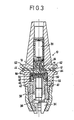
- FIG. 3 eine Schnittansicht des Spannfutters,
- FIG. 4 die im Spannfutter gemäß Figuren 2 und 3 eingesetzte elektronische Baueinheit in größerem Maßstab,
- FIG. 5 eine Stirnansicht der Baueinheit gemäß FIG. 4,
- FIG. 6 eine Schnittansicht durch eine abgewandelte Ausführungsform der elektronischen Baueinheit,
- FIG. 7 eine schematische Schnittansicht durch eine Turbine,
- FIG. 8 eine Schnittansicht des Endes der Turbinenwelle in größerem Maßstab,
- FIG. 9 eine Stirnansicht des Turbinenwellenendes längs der Linie 9-9 der FIG. 8,
- FIG. 10 eine schematische Schnittansicht durch eine Brennkraftmaschine mit Kurbelwelle und
- FIG. 11 eine Schnittansicht durch das Kurbelwellenende in größerem Maßstab.
- FIG. 1 is a view of a drilling machine,
- FIG. 2 the view of a chuck inserted in a spindle head,
- FIG. 3 is a sectional view of the chuck,
- FIG. 4 the electronic assembly used in the chuck according to FIGS. 2 and 3 on a larger scale,
- FIG. 5 shows an end view of the assembly according to FIG. 4,
- FIG. 6 shows a sectional view through a modified embodiment of the electronic assembly,
- FIG. 7 shows a schematic sectional view through a turbine,
- FIG. 8 is a sectional view of the end of the turbine shaft on a larger scale;
- FIG. 9 is an end view of the turbine shaft end taken along line 9-9 of FIG. 8th,
- FIG. 10 shows a schematic sectional view through an internal combustion engine with a crankshaft and
- FIG. 11 is a sectional view through the crankshaft end on a larger scale.
Ein Spannfutter 10 einer Bohr- oder Fräsmaschine zeigt Bine Anzahl im Boden der Greiferrille 12 in Umfangsabständen angeordnete Radialbohrungen 62, mit denen radial ausgefluchtet im Inneren des Spannfutters angeordnete Sendedioden 14 und Empfängerdioden 16 vorgesehen sind. In der Drehebene dieser Sende- und Empfängerdioden 14,16 befindet sich im Abstand neben dem Spannfutter 10 eine ortsfeste Sende-und Empfängerstation 18, die am Maschinenrahmen befestigt ist und elektrisch über die Leitung 20 mit einer Kontroll-Steuer-und Anzeigeeinheit 22 verbunden ist.A
Gemäß FIG. 2 ist in den Spindelkopf 24 eine Primärspule 26 eingesetzt, der eine Sekundärspule 28 im Spannfutter 10 für eine induktive Stromversorgung gegenüberliegt.According to FIG. 2, a
Bei dem Spannfutter 10 gemäß FIG. 3 erfolgt die Stromversorgung alternativ durch eine eingebaute Batterie 30. Das Spannfutter 10 besteht aus einem zweiteiligen Gehäuse 32, Spannbacken 34, die in einem Schiebeglied 36 geführt sind, das in einem Drehglied 38 verschraubbar ist, das seinerseits in bekannter Weise über eine Schneckenwelle 40 von außen mittels eines Schlüssels drehbar ist. Zwischen einem Flansch 42 des Drehgliedes 38 und einer Ringschulter 44 des Gehäuses 32 sind ein Kugellagerkranz 46, eine Stützring 48 und ein Ringkörper 50 angeordnet. Bei eingespanntem Werkzeug wird die axiale Komponente der Reaktionsspannkraft über das Schiebeglied 36 und das Drehglied 38, den Kugelkranz 46, den Stützring 48 auf den Ringkörper 50 übertragen, der somit unter Vorspannung steht. Der Stützring 48 trägt einen axial vorspringenden Stift 52, der den Ringkörper 50 durchsetzt und in ein Sackloch in der Ringschulter 44 des Gehäuses 32 zur Drehsicherung eingreift.In the
Der Ringkörper 50 und ein an diesen rückseitig anschließender kreiszylindrischer Block 54 bilden eine Baueinheit, die die gesamte Elektronik enthält..Im Ringkörper 50 sind in gleichen Umfangsabständen drei Paare von Drucksensoren 56 angeordnet. Im Block 54 befinden sich vier parallele mit elektronischen Bauteilen 58 bestückte Platinen 60, die bei der Ausführung gemäß FIG. 4 in Radialebenen und bei der Ausführung gemäß FIG. 6 in achsparallelen Ebenen angeordnet sind. Die elektrischen bzw. elektronischen Bauteile 58 sind intern verdrahtet und bilden eine Signalverarbeitungseinrichtung, die mit den Sensoren 56 elektrisch verbunden ist. Im Bereich des Außenumfanges des Blockes 54 sind in einer Radialebene abwechselnd in Umfangsabständen die Sendedioden 14 und die Empfängerdioden 16 angeordnet und elektrisch mit einem Verstärkerteil der Signalverarbeitungseinrichtung verbunden. Jeder dieser Dioden 14,16 ist eine Radialbohrung 62 im Schaft des Gehäuses 32 zugeordnet, durch die hindurch die Infrarotsignale der Dioden 14,16 ein- bzw. austreten können. Die Bohrungen 62 sind mit einem lichtdurchlässigen Material 64 ausgegossen.Unmittelbar hinter dem.zylindrischen Block 54 befindet sich ein zylindrisches Gehäuse mit der Batterie 30, die über einen zentralen Kontakt und einen Kontaktring die Stromversorgung zur Signalverarbeitungseinrichtung herstellt.The
Gemäß Figuren 7 bis 9 ist auf einer Welle 100 einer Turbine 102 ein ringförmiger vergossener Block 154 befestigt, der die Signalverarbeitungseinrichtung enthält, die über ein Kabel mit einem Sensor 156 verbunden ist, welcher in einer Radialbohrung der Welle 100 eingesetzt und mittels einer Schraubhülse unter Vorspannung gesetzt ist. Der Block 154 wird von einem Flanschstutzen 104 mit geringem Abstand umschlossen, der am Gehäuse der Turbine 102 befestigt ist. Im Block 154 sind in einer ersten Radialebene mehrere umfangsmäßig verteilte Sendedioden 14 und in einer dazu parallelen Radialebene mehrere Empfängerdioden 16 angeordnet. Im Flanschstutzen 104 befinden sich am Umfang verteilte Sendedioden 18a, die den Empfängerdioden 16 gegenüberliegen, sowie Empfängerdioden 18b, die den Sendedioden 14 gegenüber liegen. Die Stromzufuhr erfolgt hier induktiv über die beiden Spulen 26, 28. Von der Steuer- und Kontrolleinrichtung 22 kann somit über die Sendedioden 18a und die Empfängerdioden 16 die Auswerteinrichtung zur Signalabgabe aufgefordert werden, die die gewünschten momentanen Meßdaten des Sensors 156 über die Sendedioden 14 und die Empfängerdioden 18b an die Kontrolleinrichtung 22 liefert.According to FIGS. 7 to 9, an annular molded
Bei der Ausführung gemäß Figuren 10 und 11 ist ein vergossener Block 254 mittels einer Schraubhülse stirnseitig an eine Kurbelwelle 200 einer Brennkraftmaschine 202 befestigt. Die Welle 200 weist ein koaxiales Sackloch auf, in dem sich ein Sensor 256 befindet, der von einem zylindrischen Vorsprung des Blockes 254 unter Vorspannung gehalten ist. An der freien Stirnseite des Blockes 254 befinden sich die Sende- und Empfängerdioden 14,16, die in Umfangsabständen auf einem Kreis angeordnet sind und die in der schon beschriebenen Weise mit der stationären Sende- und Empfangsstation 18 in einer Stirnwand eines Gehäuseabschlußstutzens 204 durch einen transparenten Einsatz 206 in der Schraubkappe hindurch kommunizieren.In the embodiment according to FIGS. 10 and 11, a
Claims (10)
Priority Applications (1)
| Application Number | Priority Date | Filing Date | Title |
|---|---|---|---|
| AT86118165T ATE54769T1 (en) | 1986-01-10 | 1986-12-30 | DEVICE FOR WIRELESS TRANSMISSION OF SIGNALS FROM A ROTATING BODY. |
Applications Claiming Priority (2)
| Application Number | Priority Date | Filing Date | Title |
|---|---|---|---|
| DE3600466 | 1986-01-10 | ||
| DE19863600466 DE3600466A1 (en) | 1986-01-10 | 1986-01-10 | CHUCK FOR ROTATING TOOLS |
Publications (3)
| Publication Number | Publication Date |
|---|---|
| EP0229399A2 true EP0229399A2 (en) | 1987-07-22 |
| EP0229399A3 EP0229399A3 (en) | 1989-03-29 |
| EP0229399B1 EP0229399B1 (en) | 1990-07-18 |
Family
ID=6291591
Family Applications (1)
| Application Number | Title | Priority Date | Filing Date |
|---|---|---|---|
| EP86118165A Expired - Lifetime EP0229399B1 (en) | 1986-01-10 | 1986-12-30 | Arrangement for wireless signal transmission from a rotating body |
Country Status (10)
| Country | Link |
|---|---|
| US (1) | US4761101A (en) |
| EP (1) | EP0229399B1 (en) |
| JP (1) | JPS62229397A (en) |
| KR (1) | KR920008799B1 (en) |
| CN (1) | CN1008406B (en) |
| AT (1) | ATE54769T1 (en) |
| CA (1) | CA1261024A (en) |
| DE (2) | DE3600466A1 (en) |
| ES (1) | ES2016251B3 (en) |
| GR (1) | GR3000799T3 (en) |
Cited By (11)
| Publication number | Priority date | Publication date | Assignee | Title |
|---|---|---|---|---|
| EP0325917A2 (en) * | 1988-01-23 | 1989-08-02 | FEV Motorentechnik GmbH & Co. KG | Apparatus for measuring and transmitting the combustion radiation in the combustion chamber of combustion engines |
| EP0431274A2 (en) * | 1989-12-08 | 1991-06-12 | Röhm, Günter Horst | Drilling chuck |
| EP0542667A2 (en) * | 1991-11-14 | 1993-05-19 | HILTI Aktiengesellschaft | Speed regulating device for a hand-held machine tool and its method of manufacture |
| US5248229A (en) * | 1992-04-14 | 1993-09-28 | Otto Bilz, Werkzeugfabrick Gmbh & Co. | Chuck for tool, especially drilling tool |
| EP0598924A1 (en) * | 1992-06-18 | 1994-06-01 | Kabushiki Kaisha Yaskawa Denki | Non-contact power transmission apparatus, non-contact signal transmitter, separation type machine using them and control method thereof |
| US5626514A (en) * | 1996-03-19 | 1997-05-06 | Rothove; Herman H. | Small game skinning device |
| US5791836A (en) * | 1993-09-13 | 1998-08-11 | Komet Praezisionswerkzeuge Robert Breuning Gmbh | Tool head with external current supply |
| WO2012119908A1 (en) * | 2011-03-10 | 2012-09-13 | Komet Group Gmbh | Rotary transmission device for machine tools |
| US9079713B2 (en) | 2008-05-29 | 2015-07-14 | Rite-Hite Holding Corporation | Head curtains for dock shelters or dock seals |
| DE102015212810A1 (en) | 2015-07-08 | 2017-01-12 | Sauer Gmbh | Device for generating an ultrasonic vibration of a tool and for measuring vibration parameters |
| US10967434B2 (en) | 2016-08-12 | 2021-04-06 | Big Kaiser Präzisionswerkzeuge Ag | Boring head with an electronic unit |
Families Citing this family (33)
| Publication number | Priority date | Publication date | Assignee | Title |
|---|---|---|---|---|
| JPH029555A (en) * | 1988-03-24 | 1990-01-12 | Omron Tateisi Electron Co | Tool damage detecting device |
| US4963804A (en) * | 1989-07-10 | 1990-10-16 | Westinghouse Electric Corp. | Apparatus and method for reducing vibration of rotating machinery |
| DE4007838A1 (en) * | 1990-03-12 | 1991-09-19 | Dittel Walter Gmbh | DEVICE FOR TOUCH DETECTION |
| US5273295A (en) * | 1993-02-22 | 1993-12-28 | Lieberman Robert L | Debuckler |
| JP3250581B2 (en) * | 1993-08-26 | 2002-01-28 | 石川島播磨重工業株式会社 | How to fix the transmitter for rotating body |
| EP0719404B1 (en) * | 1993-09-16 | 1998-01-14 | Werner Kluft | Sensor system |
| DE4431845A1 (en) * | 1994-09-07 | 1996-03-14 | Komet Stahlhalter Werkzeug | Method and device for the detection and compensation of joining and wear errors during fine boring |
| US5791841A (en) * | 1996-10-15 | 1998-08-11 | Zones; Harry | Quill interlock |
| US6166506A (en) * | 1998-06-19 | 2000-12-26 | Tregaskiss, Ltd. | Wireless safety clutch |
| US6158929A (en) * | 1998-07-01 | 2000-12-12 | Bae Systems Plc | Electronically triggered surface sensor unit |
| US6257077B1 (en) * | 1998-09-08 | 2001-07-10 | Alan C. Patterson | Remotely powered sensing arrangement for a rotatable device |
| JP3701799B2 (en) * | 1998-10-06 | 2005-10-05 | 村田機械株式会社 | Yarn processing roller |
| US6419426B1 (en) * | 2000-07-05 | 2002-07-16 | Advanced Integration Technology, Inc. | Numeric controlled drilling jig-multiple-axis aerospace drilling machine |
| US6642720B2 (en) * | 2001-07-25 | 2003-11-04 | General Electric Company | Wireless sensor assembly for circumferential monitoring of gas stream properties |
| WO2003089188A1 (en) * | 2002-04-20 | 2003-10-30 | Renishaw Plc | Machine adaptation |
| US6757636B2 (en) | 2002-07-19 | 2004-06-29 | Alstom Technology Ltd. | Computerized electronic runout |
| DE102005021629A1 (en) * | 2005-05-06 | 2006-11-09 | Röhm Gmbh | drilling |
| EP2025445B1 (en) * | 2005-09-12 | 2013-05-29 | Paul Müller GmbH & Co. KG Unternehmensbeteiligungen | Spindle with data recording element |
| DE102006030834B4 (en) * | 2006-07-04 | 2009-11-26 | ARTIS Gesellschaft für angewandte Meßtechnik mbH | Sensor system for machine tools |
| CN102015203A (en) * | 2008-03-17 | 2011-04-13 | 克里斯托弗·A·苏普罗克 | Smart machining system and smart tool holder therefor |
| DE102008055971A1 (en) * | 2008-11-05 | 2010-05-06 | Komet Group Gmbh | Machining center with rotary transformer for electrical energy |
| DE102010003338A1 (en) * | 2010-03-26 | 2011-09-29 | Komet Group Gmbh | Machine tool with rotary transformer for data |
| CN103801986B (en) * | 2014-02-17 | 2016-10-05 | 广东海洋大学 | A kind of built-in optical fiber real-time continuous infrared measurement of temperature handle of a knife |
| CN104084843A (en) * | 2014-06-27 | 2014-10-08 | 赵秋燕 | Deformation measuring device for drilling machine |
| CN105522198A (en) * | 2014-09-30 | 2016-04-27 | 无锡利博科技有限公司 | Drilling device with pressure alarm indicator |
| CN105436540A (en) * | 2014-09-30 | 2016-03-30 | 无锡利博科技有限公司 | Safety drilling device |
| ES2705411T3 (en) * | 2015-06-05 | 2019-03-25 | Gleason Cutting Tools Corp | Tools with removable information device |
| FR3039450B1 (en) * | 2015-07-29 | 2017-08-11 | Airbus Operations Sas | TOOL SUPPORT SYSTEM |
| DE102018111044A1 (en) | 2018-05-08 | 2019-11-14 | Albrecht Präzision GmbH & Co. KG | toolholder |
| TW202031408A (en) * | 2019-02-27 | 2020-09-01 | 鼎朋企業股份有限公司 | Tool holder for ultrasonic machining |
| TWI674942B (en) * | 2019-02-27 | 2019-10-21 | 鼎朋企業股份有限公司 | Tool holder having an arrangement for delivering coolant and transmitting electric power |
| TW202031420A (en) * | 2019-02-27 | 2020-09-01 | 鼎朋企業股份有限公司 | Modular tool holder for ultrasonic machining |
| DE102021124907A1 (en) | 2021-09-27 | 2023-03-30 | Schunk Gmbh & Co. Kg Spann- Und Greiftechnik | Clamping device, sensor module and sensor arrangement |
Citations (6)
| Publication number | Priority date | Publication date | Assignee | Title |
|---|---|---|---|---|
| DE1954643A1 (en) * | 1968-11-05 | 1970-06-25 | Lehoczky Dipl Ing Kalman | Device for the transmission of measured values between counter-rotating systems |
| US4213119A (en) * | 1976-04-29 | 1980-07-15 | Energy Optics, Inc. | Remote meter reading system providing demand readings and load control from conventional KWH meters |
| US4310767A (en) * | 1979-04-11 | 1982-01-12 | Wyle Laboratories | Data interface between rotating and nonrotating members |
| EP0108857A2 (en) * | 1982-11-10 | 1984-05-23 | Günter Horst Röhm | Power-actuated clamping chuck |
| FR2566572A1 (en) * | 1984-06-21 | 1985-12-27 | Ramses | Device for contactless control and linkage, for automated equipment, in particular with machine tools |
| EP0099992B1 (en) * | 1982-07-29 | 1988-05-25 | Robert Bosch Gmbh | Machine tool with control device |
Family Cites Families (7)
| Publication number | Priority date | Publication date | Assignee | Title |
|---|---|---|---|---|
| US2978689A (en) * | 1955-05-09 | 1961-04-04 | Cross Co | Control mechanism for machine tools and the like |
| US3872285A (en) * | 1974-05-31 | 1975-03-18 | Westinghouse Electric Corp | Control system for sensing the vibration and lateral force on a cutting tool |
| US4090802A (en) * | 1976-12-27 | 1978-05-23 | Otto Bilz Werkzeugfabrik | Radio detector for detecting dull and broken tools |
| DE3019751C2 (en) * | 1980-05-23 | 1983-12-29 | J.G. Weisser Söhne, 7742 St Georgen | Device for measuring the cutting force of cutting tools in a multiple tool holder |
| DE3046485C2 (en) * | 1980-12-10 | 1986-11-13 | Otto Bilz, Werkzeugfabrik, 7302 Ostfildern | Chuck for tools, in particular drilling tools |
| JPS58186550A (en) * | 1982-04-23 | 1983-10-31 | Yoshiaki Kakino | Tool break preventive device |
| DE3404009C1 (en) * | 1984-02-06 | 1985-08-22 | Erwin Leukhardt Gmbh & Co, 7200 Tuttlingen | Torque measuring device |
-
1986
- 1986-01-10 DE DE19863600466 patent/DE3600466A1/en not_active Withdrawn
- 1986-12-30 DE DE8686118165T patent/DE3672793D1/en not_active Expired - Lifetime
- 1986-12-30 ES ES86118165T patent/ES2016251B3/en not_active Expired - Lifetime
- 1986-12-30 EP EP86118165A patent/EP0229399B1/en not_active Expired - Lifetime
- 1986-12-30 AT AT86118165T patent/ATE54769T1/en not_active IP Right Cessation
- 1986-12-31 US US06/948,321 patent/US4761101A/en not_active Expired - Fee Related
-
1987
- 1987-01-07 CA CA000526857A patent/CA1261024A/en not_active Expired
- 1987-01-08 JP JP62002578A patent/JPS62229397A/en active Pending
- 1987-01-08 KR KR1019870000094A patent/KR920008799B1/en active IP Right Grant
- 1987-01-09 CN CN87100108A patent/CN1008406B/en not_active Expired
-
1990
- 1990-09-14 GR GR90400654T patent/GR3000799T3/en unknown
Patent Citations (6)
| Publication number | Priority date | Publication date | Assignee | Title |
|---|---|---|---|---|
| DE1954643A1 (en) * | 1968-11-05 | 1970-06-25 | Lehoczky Dipl Ing Kalman | Device for the transmission of measured values between counter-rotating systems |
| US4213119A (en) * | 1976-04-29 | 1980-07-15 | Energy Optics, Inc. | Remote meter reading system providing demand readings and load control from conventional KWH meters |
| US4310767A (en) * | 1979-04-11 | 1982-01-12 | Wyle Laboratories | Data interface between rotating and nonrotating members |
| EP0099992B1 (en) * | 1982-07-29 | 1988-05-25 | Robert Bosch Gmbh | Machine tool with control device |
| EP0108857A2 (en) * | 1982-11-10 | 1984-05-23 | Günter Horst Röhm | Power-actuated clamping chuck |
| FR2566572A1 (en) * | 1984-06-21 | 1985-12-27 | Ramses | Device for contactless control and linkage, for automated equipment, in particular with machine tools |
Cited By (26)
| Publication number | Priority date | Publication date | Assignee | Title |
|---|---|---|---|---|
| EP0325917A2 (en) * | 1988-01-23 | 1989-08-02 | FEV Motorentechnik GmbH & Co. KG | Apparatus for measuring and transmitting the combustion radiation in the combustion chamber of combustion engines |
| DE3801949A1 (en) * | 1988-01-23 | 1989-08-03 | Fev Motorentech Gmbh & Co Kg | DEVICE FOR TRANSMITTING ELECTROMAGNETIC SHAFTS |
| US4918982A (en) * | 1988-01-23 | 1990-04-24 | Fev Motorentechnik Gmbh & Co. Kg | Device for measuring and transmitting the combustion radiation in the combustion chamber of combustion engines |
| EP0325917A3 (en) * | 1988-01-23 | 1990-07-04 | Fev Motorentechnik Gmbh & Co. Kg | Apparatus for measuring and transmitting the combustion radiation in the combustion chamber of combustion engines |
| EP0431274A2 (en) * | 1989-12-08 | 1991-06-12 | Röhm, Günter Horst | Drilling chuck |
| EP0431274A3 (en) * | 1989-12-08 | 1991-12-11 | Roehm, Guenter Horst | Drilling chuck |
| EP0542667A2 (en) * | 1991-11-14 | 1993-05-19 | HILTI Aktiengesellschaft | Speed regulating device for a hand-held machine tool and its method of manufacture |
| EP0542667A3 (en) * | 1991-11-14 | 1993-12-08 | Hilti Ag | Speed regulating device for a hand-held machine tool and its method of manufacture |
| US5248229A (en) * | 1992-04-14 | 1993-09-28 | Otto Bilz, Werkzeugfabrick Gmbh & Co. | Chuck for tool, especially drilling tool |
| EP0565748A1 (en) * | 1992-04-14 | 1993-10-20 | OTTO BILZ Werkzeugfabrik GmbH & Co. | Tool chuck |
| EP0598924A1 (en) * | 1992-06-18 | 1994-06-01 | Kabushiki Kaisha Yaskawa Denki | Non-contact power transmission apparatus, non-contact signal transmitter, separation type machine using them and control method thereof |
| EP0598924A4 (en) * | 1992-06-18 | 1995-01-25 | Yaskawa Denki Seisakusho Kk | Non-contact power transmission apparatus, non-contact signal transmitter, separation type machine using them and control method thereof. |
| US5637973A (en) * | 1992-06-18 | 1997-06-10 | Kabushiki Kaisha Yaskawa Denki | Noncontacting electric power transfer apparatus, noncontacting signal transfer apparatus, split-type mechanical apparatus employing these transfer apparatus and a control method for controlling same |
| EP0845794A1 (en) * | 1992-06-18 | 1998-06-03 | Kabushiki Kaisha Yaskawa Denki | Noncontacting signal transfer apparatus |
| EP0845793A1 (en) * | 1992-06-18 | 1998-06-03 | Kabushiki Kaisha Yaskawa Denki | Noncontacting signal transfer apparatus |
| US5791836A (en) * | 1993-09-13 | 1998-08-11 | Komet Praezisionswerkzeuge Robert Breuning Gmbh | Tool head with external current supply |
| US5626514A (en) * | 1996-03-19 | 1997-05-06 | Rothove; Herman H. | Small game skinning device |
| US9079713B2 (en) | 2008-05-29 | 2015-07-14 | Rite-Hite Holding Corporation | Head curtains for dock shelters or dock seals |
| US9409731B2 (en) | 2008-05-29 | 2016-08-09 | Rite-Hite Holding Corporation | Head curtains for dock shelters or dock seals |
| WO2012119908A1 (en) * | 2011-03-10 | 2012-09-13 | Komet Group Gmbh | Rotary transmission device for machine tools |
| CN103402699A (en) * | 2011-03-10 | 2013-11-20 | 彗星集团有限公司 | Rotary transmission device for machine tools |
| CN103402699B (en) * | 2011-03-10 | 2016-04-20 | 彗星集团有限公司 | For the rotational transmitter of lathe |
| DE102015212810A1 (en) | 2015-07-08 | 2017-01-12 | Sauer Gmbh | Device for generating an ultrasonic vibration of a tool and for measuring vibration parameters |
| US10809123B2 (en) | 2015-07-08 | 2020-10-20 | Sauer Gmbh | Device for generating an ultrasonic vibration of a tool and for measuring vibration parameters |
| DE102015212810B4 (en) | 2015-07-08 | 2023-10-19 | Sauer Gmbh | Device for generating an ultrasonic vibration of a tool and for measuring vibration parameters |
| US10967434B2 (en) | 2016-08-12 | 2021-04-06 | Big Kaiser Präzisionswerkzeuge Ag | Boring head with an electronic unit |
Also Published As
| Publication number | Publication date |
|---|---|
| CN87100108A (en) | 1987-07-22 |
| US4761101A (en) | 1988-08-02 |
| DE3600466A1 (en) | 1987-07-16 |
| KR920008799B1 (en) | 1992-10-09 |
| ATE54769T1 (en) | 1990-08-15 |
| EP0229399B1 (en) | 1990-07-18 |
| KR870006952A (en) | 1987-08-13 |
| DE3672793D1 (en) | 1990-08-23 |
| JPS62229397A (en) | 1987-10-08 |
| GR3000799T3 (en) | 1991-10-10 |
| CN1008406B (en) | 1990-06-13 |
| EP0229399A3 (en) | 1989-03-29 |
| ES2016251B3 (en) | 1990-11-01 |
| CA1261024A (en) | 1989-09-26 |
Similar Documents
| Publication | Publication Date | Title |
|---|---|---|
| EP0229399A2 (en) | Arrangement for wireless signal transmission from a rotating body | |
| EP3365132B1 (en) | Tool holder with integrated sensor system | |
| EP1924834B1 (en) | Sensor arrangement | |
| EP0164574B1 (en) | Screw driving device | |
| EP0901881B1 (en) | Tool or tool holder | |
| DE19916710B4 (en) | Tool drive device, in particular for machine tools | |
| EP3028804A1 (en) | Transmission device, in particular for energy and/or signal transmission | |
| EP0452556B1 (en) | Sensor for an electric motor-driven steering wheel | |
| EP3447858A1 (en) | Spindle device for use on a numerically controlled machine tool | |
| DE19617887A1 (en) | Tool | |
| EP2843359A1 (en) | Coupling with a drive-side coupling part and with an output-side coupling part | |
| WO2018095472A1 (en) | Tool holder for a machining tool of a machine tool, and measuring device | |
| EP3696435A1 (en) | Universal joint spider with a temperature sensor and universal joint with such a spider | |
| EP0935541A1 (en) | Device for determining the angular position of the steering wheel in a motor vehicle | |
| EP1617541B1 (en) | Direct drive with an angular position detector | |
| DE102007020940B3 (en) | Damages detecting and monitoring device for e.g. tracks of crane's ball bearing ring, has energy source with rail extending over bearing periphery part and storage to store energy, and transmitting device with contact assigned to rail | |
| WO2018054421A1 (en) | Torque-measuring arrangement | |
| EP0740138B1 (en) | Arrangement for measuring the torque input of a multi-screw extruder | |
| EP0214583A1 (en) | Facing and boring head | |
| DE102017124667A1 (en) | Measuring system for monitoring a spindle | |
| DE102017117759A1 (en) | Sensor retrofit kit | |
| DE102019218884A1 (en) | Slewing bearings | |
| DE4014431C1 (en) | ||
| DE3743432A1 (en) | Balancing arrangement | |
| DE102014118359A1 (en) | Rotor assembly for a slip ring assembly and rotary joint assembly with such a rotor assembly |
Legal Events
| Date | Code | Title | Description |
|---|---|---|---|
| PUAI | Public reference made under article 153(3) epc to a published international application that has entered the european phase |
Free format text: ORIGINAL CODE: 0009012 |
|
| AK | Designated contracting states |
Kind code of ref document: A2 Designated state(s): AT BE CH DE ES FR GB GR IT LI LU NL SE |
|
| PUAL | Search report despatched |
Free format text: ORIGINAL CODE: 0009013 |
|
| AK | Designated contracting states |
Kind code of ref document: A3 Designated state(s): AT BE CH DE ES FR GB GR IT LI LU NL SE |
|
| 17P | Request for examination filed |
Effective date: 19890908 |
|
| 17Q | First examination report despatched |
Effective date: 19891116 |
|
| DIN1 | Information on inventor provided before grant (deleted) | ||
| RAP1 | Party data changed (applicant data changed or rights of an application transferred) |
Owner name: ZETTL GMBH CNC PRAEZISIONS- UND SONDERWERKZEUGE |
|
| RIN1 | Information on inventor provided before grant (corrected) |
Inventor name: ZETTL, OTTO |
|
| GRAA | (expected) grant |
Free format text: ORIGINAL CODE: 0009210 |
|
| AK | Designated contracting states |
Kind code of ref document: B1 Designated state(s): AT BE CH DE ES FR GB GR IT LI LU NL SE |
|
| REF | Corresponds to: |
Ref document number: 54769 Country of ref document: AT Date of ref document: 19900815 Kind code of ref document: T |
|
| ITF | It: translation for a ep patent filed |
Owner name: ORGANIZZAZIONE D'AGOSTINI |
|
| GBT | Gb: translation of ep patent filed (gb section 77(6)(a)/1977) | ||
| REF | Corresponds to: |
Ref document number: 3672793 Country of ref document: DE Date of ref document: 19900823 |
|
| ET | Fr: translation filed | ||
| REG | Reference to a national code |
Ref country code: GR Ref legal event code: FG4A Free format text: 3000799 |
|
| PLBE | No opposition filed within time limit |
Free format text: ORIGINAL CODE: 0009261 |
|
| STAA | Information on the status of an ep patent application or granted ep patent |
Free format text: STATUS: NO OPPOSITION FILED WITHIN TIME LIMIT |
|
| 26N | No opposition filed | ||
| PGFP | Annual fee paid to national office [announced via postgrant information from national office to epo] |
Ref country code: LU Payment date: 19911129 Year of fee payment: 6 Ref country code: BE Payment date: 19911129 Year of fee payment: 6 |
|
| PGFP | Annual fee paid to national office [announced via postgrant information from national office to epo] |
Ref country code: GR Payment date: 19911211 Year of fee payment: 6 |
|
| PGFP | Annual fee paid to national office [announced via postgrant information from national office to epo] |
Ref country code: ES Payment date: 19911217 Year of fee payment: 6 |
|
| PGFP | Annual fee paid to national office [announced via postgrant information from national office to epo] |
Ref country code: NL Payment date: 19911231 Year of fee payment: 6 |
|
| EPTA | Lu: last paid annual fee | ||
| PG25 | Lapsed in a contracting state [announced via postgrant information from national office to epo] |
Ref country code: LU Free format text: LAPSE BECAUSE OF NON-PAYMENT OF DUE FEES Effective date: 19921230 |
|
| PG25 | Lapsed in a contracting state [announced via postgrant information from national office to epo] |
Ref country code: ES Free format text: LAPSE BECAUSE OF EXPIRATION OF PROTECTION Effective date: 19921231 Ref country code: BE Effective date: 19921231 |
|
| BERE | Be: lapsed |
Owner name: ZETTL G.M.B.H. CNC PRAZISIONS- UND SONDERWERKZEUG Effective date: 19921231 |
|
| PG25 | Lapsed in a contracting state [announced via postgrant information from national office to epo] |
Ref country code: GR Free format text: THE PATENT HAS BEEN ANNULLED BY A DECISION OF A NATIONAL AUTHORITY Effective date: 19930630 |
|
| PG25 | Lapsed in a contracting state [announced via postgrant information from national office to epo] |
Ref country code: NL Effective date: 19930701 |
|
| NLV4 | Nl: lapsed or anulled due to non-payment of the annual fee | ||
| REG | Reference to a national code |
Ref country code: GR Ref legal event code: MM2A Free format text: 3000799 |
|
| EAL | Se: european patent in force in sweden |
Ref document number: 86118165.9 |
|
| PGFP | Annual fee paid to national office [announced via postgrant information from national office to epo] |
Ref country code: SE Payment date: 19961209 Year of fee payment: 11 |
|
| PGFP | Annual fee paid to national office [announced via postgrant information from national office to epo] |
Ref country code: CH Payment date: 19961224 Year of fee payment: 11 |
|
| PGFP | Annual fee paid to national office [announced via postgrant information from national office to epo] |
Ref country code: FR Payment date: 19961227 Year of fee payment: 11 |
|
| PGFP | Annual fee paid to national office [announced via postgrant information from national office to epo] |
Ref country code: AT Payment date: 19961230 Year of fee payment: 11 |
|
| PGFP | Annual fee paid to national office [announced via postgrant information from national office to epo] |
Ref country code: GB Payment date: 19971222 Year of fee payment: 12 |
|
| PG25 | Lapsed in a contracting state [announced via postgrant information from national office to epo] |
Ref country code: AT Free format text: LAPSE BECAUSE OF NON-PAYMENT OF DUE FEES Effective date: 19971230 |
|
| PG25 | Lapsed in a contracting state [announced via postgrant information from national office to epo] |
Ref country code: SE Free format text: LAPSE BECAUSE OF NON-PAYMENT OF DUE FEES Effective date: 19971231 Ref country code: LI Free format text: LAPSE BECAUSE OF NON-PAYMENT OF DUE FEES Effective date: 19971231 Ref country code: FR Free format text: THE PATENT HAS BEEN ANNULLED BY A DECISION OF A NATIONAL AUTHORITY Effective date: 19971231 Ref country code: CH Free format text: LAPSE BECAUSE OF NON-PAYMENT OF DUE FEES Effective date: 19971231 |
|
| PGFP | Annual fee paid to national office [announced via postgrant information from national office to epo] |
Ref country code: DE Payment date: 19980213 Year of fee payment: 12 |
|
| REG | Reference to a national code |
Ref country code: CH Ref legal event code: PL |
|
| EUG | Se: european patent has lapsed |
Ref document number: 86118165.9 |
|
| REG | Reference to a national code |
Ref country code: FR Ref legal event code: ST |
|
| PG25 | Lapsed in a contracting state [announced via postgrant information from national office to epo] |
Ref country code: GB Free format text: LAPSE BECAUSE OF NON-PAYMENT OF DUE FEES Effective date: 19981230 |
|
| GBPC | Gb: european patent ceased through non-payment of renewal fee |
Effective date: 19981230 |
|
| PG25 | Lapsed in a contracting state [announced via postgrant information from national office to epo] |
Ref country code: DE Free format text: LAPSE BECAUSE OF NON-PAYMENT OF DUE FEES Effective date: 19991001 |
|
| REG | Reference to a national code |
Ref country code: ES Ref legal event code: FD2A Effective date: 20010301 |
|
| PG25 | Lapsed in a contracting state [announced via postgrant information from national office to epo] |
Ref country code: IT Free format text: LAPSE BECAUSE OF NON-PAYMENT OF DUE FEES;WARNING: LAPSES OF ITALIAN PATENTS WITH EFFECTIVE DATE BEFORE 2007 MAY HAVE OCCURRED AT ANY TIME BEFORE 2007. THE CORRECT EFFECTIVE DATE MAY BE DIFFERENT FROM THE ONE RECORDED. Effective date: 20051230 |