EP0224380A2 - Valve assembly - Google Patents
Valve assembly Download PDFInfo
- Publication number
- EP0224380A2 EP0224380A2 EP19860309066 EP86309066A EP0224380A2 EP 0224380 A2 EP0224380 A2 EP 0224380A2 EP 19860309066 EP19860309066 EP 19860309066 EP 86309066 A EP86309066 A EP 86309066A EP 0224380 A2 EP0224380 A2 EP 0224380A2
- Authority
- EP
- European Patent Office
- Prior art keywords
- valve
- valve member
- valve assembly
- adapter
- housing
- Prior art date
- Legal status (The legal status is an assumption and is not a legal conclusion. Google has not performed a legal analysis and makes no representation as to the accuracy of the status listed.)
- Withdrawn
Links
- 239000007788 liquid Substances 0.000 claims description 37
- 238000007789 sealing Methods 0.000 claims description 27
- 235000013405 beer Nutrition 0.000 description 45
- 239000007921 spray Substances 0.000 description 16
- 239000003380 propellant Substances 0.000 description 14
- 239000000443 aerosol Substances 0.000 description 13
- 239000012530 fluid Substances 0.000 description 12
- 230000013011 mating Effects 0.000 description 8
- 229910002092 carbon dioxide Inorganic materials 0.000 description 5
- 238000004806 packaging method and process Methods 0.000 description 5
- 239000004033 plastic Substances 0.000 description 5
- 229920003023 plastic Polymers 0.000 description 5
- CURLTUGMZLYLDI-UHFFFAOYSA-N Carbon dioxide Chemical compound O=C=O CURLTUGMZLYLDI-UHFFFAOYSA-N 0.000 description 4
- 238000004891 communication Methods 0.000 description 4
- 238000010276 construction Methods 0.000 description 4
- 238000000465 moulding Methods 0.000 description 4
- 238000012536 packaging technology Methods 0.000 description 4
- 238000013019 agitation Methods 0.000 description 3
- 230000000994 depressogenic effect Effects 0.000 description 3
- 238000013461 design Methods 0.000 description 3
- 238000011161 development Methods 0.000 description 3
- 238000005516 engineering process Methods 0.000 description 3
- 239000002184 metal Substances 0.000 description 3
- 239000001569 carbon dioxide Substances 0.000 description 2
- 230000001590 oxidative effect Effects 0.000 description 2
- 239000000047 product Substances 0.000 description 2
- 238000003466 welding Methods 0.000 description 2
- 229920002799 BoPET Polymers 0.000 description 1
- 239000005041 Mylar™ Substances 0.000 description 1
- 239000004698 Polyethylene Substances 0.000 description 1
- 230000000712 assembly Effects 0.000 description 1
- 238000000429 assembly Methods 0.000 description 1
- 230000002457 bidirectional effect Effects 0.000 description 1
- 230000000903 blocking effect Effects 0.000 description 1
- 230000006866 deterioration Effects 0.000 description 1
- 238000007599 discharging Methods 0.000 description 1
- 229920002457 flexible plastic Polymers 0.000 description 1
- 239000011521 glass Substances 0.000 description 1
- 238000002347 injection Methods 0.000 description 1
- 239000007924 injection Substances 0.000 description 1
- 238000003780 insertion Methods 0.000 description 1
- 230000037431 insertion Effects 0.000 description 1
- 239000012263 liquid product Substances 0.000 description 1
- 239000000463 material Substances 0.000 description 1
- 238000000034 method Methods 0.000 description 1
- 239000002991 molded plastic Substances 0.000 description 1
- 238000010137 moulding (plastic) Methods 0.000 description 1
- 229920000728 polyester Polymers 0.000 description 1
- -1 polyethylene Polymers 0.000 description 1
- 229920000573 polyethylene Polymers 0.000 description 1
- 230000036316 preload Effects 0.000 description 1
- 238000004064 recycling Methods 0.000 description 1
Images


Classifications
-
- B—PERFORMING OPERATIONS; TRANSPORTING
- B65—CONVEYING; PACKING; STORING; HANDLING THIN OR FILAMENTARY MATERIAL
- B65D—CONTAINERS FOR STORAGE OR TRANSPORT OF ARTICLES OR MATERIALS, e.g. BAGS, BARRELS, BOTTLES, BOXES, CANS, CARTONS, CRATES, DRUMS, JARS, TANKS, HOPPERS, FORWARDING CONTAINERS; ACCESSORIES, CLOSURES, OR FITTINGS THEREFOR; PACKAGING ELEMENTS; PACKAGES
- B65D83/00—Containers or packages with special means for dispensing contents
- B65D83/14—Containers or packages with special means for dispensing contents for delivery of liquid or semi-liquid contents by internal gaseous pressure, i.e. aerosol containers comprising propellant for a product delivered by a propellant
- B65D83/42—Filling or charging means
- B65D83/425—Delivery valves permitting filling or charging
-
- B—PERFORMING OPERATIONS; TRANSPORTING
- B65—CONVEYING; PACKING; STORING; HANDLING THIN OR FILAMENTARY MATERIAL
- B65D—CONTAINERS FOR STORAGE OR TRANSPORT OF ARTICLES OR MATERIALS, e.g. BAGS, BARRELS, BOTTLES, BOXES, CANS, CARTONS, CRATES, DRUMS, JARS, TANKS, HOPPERS, FORWARDING CONTAINERS; ACCESSORIES, CLOSURES, OR FITTINGS THEREFOR; PACKAGING ELEMENTS; PACKAGES
- B65D83/00—Containers or packages with special means for dispensing contents
- B65D83/14—Containers or packages with special means for dispensing contents for delivery of liquid or semi-liquid contents by internal gaseous pressure, i.e. aerosol containers comprising propellant for a product delivered by a propellant
- B65D83/44—Valves specially adapted therefor; Regulating devices
- B65D83/52—Valves specially adapted therefor; Regulating devices for metering
- B65D83/54—Metering valves ; Metering valve assemblies
-
- B—PERFORMING OPERATIONS; TRANSPORTING
- B67—OPENING, CLOSING OR CLEANING BOTTLES, JARS OR SIMILAR CONTAINERS; LIQUID HANDLING
- B67D—DISPENSING, DELIVERING OR TRANSFERRING LIQUIDS, NOT OTHERWISE PROVIDED FOR
- B67D1/00—Apparatus or devices for dispensing beverages on draught
- B67D1/08—Details
- B67D1/0829—Keg connection means
- B67D1/0831—Keg connection means combined with valves
- B67D1/0832—Keg connection means combined with valves with two valves disposed concentrically
-
- Y—GENERAL TAGGING OF NEW TECHNOLOGICAL DEVELOPMENTS; GENERAL TAGGING OF CROSS-SECTIONAL TECHNOLOGIES SPANNING OVER SEVERAL SECTIONS OF THE IPC; TECHNICAL SUBJECTS COVERED BY FORMER USPC CROSS-REFERENCE ART COLLECTIONS [XRACs] AND DIGESTS
- Y10—TECHNICAL SUBJECTS COVERED BY FORMER USPC
- Y10T—TECHNICAL SUBJECTS COVERED BY FORMER US CLASSIFICATION
- Y10T137/00—Fluid handling
- Y10T137/2931—Diverse fluid containing pressure systems
- Y10T137/3115—Gas pressure storage over or displacement of liquid
- Y10T137/3127—With gas maintenance or application
- Y10T137/314—Unitary mounting for gas pressure inlet and liquid outlet
-
- Y—GENERAL TAGGING OF NEW TECHNOLOGICAL DEVELOPMENTS; GENERAL TAGGING OF CROSS-SECTIONAL TECHNOLOGIES SPANNING OVER SEVERAL SECTIONS OF THE IPC; TECHNICAL SUBJECTS COVERED BY FORMER USPC CROSS-REFERENCE ART COLLECTIONS [XRACs] AND DIGESTS
- Y10—TECHNICAL SUBJECTS COVERED BY FORMER USPC
- Y10T—TECHNICAL SUBJECTS COVERED BY FORMER US CLASSIFICATION
- Y10T137/00—Fluid handling
- Y10T137/598—With repair, tapping, assembly, or disassembly means
- Y10T137/612—Tapping a pipe, keg, or apertured tank under pressure
- Y10T137/613—With valved closure or bung
- Y10T137/6137—Longitudinal movement of valve
Definitions
- the present invention provides a valve assembly, which comprises an insert dimensioned and configured to fit in a necked opening of a container, said insert defining a valve housing, a valve member slideably mounted in said valve housing, said valve housing having a plurality of apertures located along a path of travel of said valve member in said valve housing, the apertures extending through the housing to an interior surface thereof, said valve member and said valve housing having a plurality of projections spaced along a length of said valve member and said valve housing extending between the interior surface of said valve housing and said valve member in sealing relationship, the projections, valve housing interior surface, apertures and valve member coacting to provide a flow path through said valve when the valve member is in a first position and to seal the flow path when the valve member is in a second position, and means biasing said valve member to the second position.
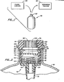
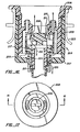
- FIG. 1 there is shown a container 50 for draft beer, incorporating a valve assembly 52 in accordance with the invention. As indicated at 54 and 56, the valve assembly 52 is used both for filling the container 50 with the draft beer and for dispensing the beer from the container 50.
- valve assembly 52 has a valve housing 64, consisting of a generally cylindrical portion 66 and a syphon tube flange 68 attached to the cylindrical portion 66, such as by ultrasonic bonding or spin welding.
- a syphon tube 70 is attached to the syphon tube flange 68.
- the syphon tube 70 and flange 68 may be integrally formed.
- the cylindrical portion 66 has a flange 72 around top 74, by which the cylindrical portion 66 is sealed to neck 76 of the container 50, such as by ultrasonic bonding or spin welding.
- Top 74 of the portion 66 has a circular opening 78.
- a first set of apertures 80 extends from exterior surface 82 of the portion 66 to its interior surface 84 near the top 74.
- a set of grooves 86 extends vertically along the inside surface 84 of the portion 66 just above the syphon tube flange 68.
- Valve member 88 is slidably movable inside the valve housing 64 between the top 74 and the syphon tube flange 68.
- the valve member 88 has a cylindrical body 90 and flanges 92, 94 and 96, which engage the inside surface 84 of the cylindrical portion 66 in sealing relationship.
- An upper portion 98 of reduced diameter extends through the opening 78 in top 74 of the housing 64.
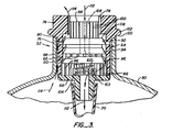
- Top portion 98 has a plurality of slots 100 to allow air to escape through the opening 78 when the valve member 88 is pushed away from the top 74 of the housing 64 (see Figure 3).
- a spring 102 urges the valve member 88 against the top 74 of the housing 64 to keep the valve assembly 52 in a normally closed position.
- Mating projections 104 and 161 (best shown in Figures 5 and 6) on the syphon tube flange 68 and the valve member 88, respectively, hold the spring 102 in position.
- the valve member 88 has a centrally disposed bore 108 extending downward to apertures 110 between the flanges 94 and 96.
- valve member 88 is displaced downward to the position shown in Figure 3. This opens a flow path for beer used to fill the container 50, indicated at 112, through the bore 108, apertures 110, grooves 86 and tube 70.
- a second flow path indicated at 114 is opened between neck 76 of the container 50, portion 66 of the housing 64, through apertures 80, between housing top 74 and top 98 of the valve member 88.
- air is exhausted from the container 50 through the flow path 114.
- valve member 88 When the container 50 is filled with beer, downward force on the valve member 88 is removed, so that spring 102 will return the valve member 88 to the position shown in Figure 2, with surface 118 of the valve member 88 in sealing relationship against top 74 of the housing 64. Carbonation pressure from the beer further serves to urge the surface 118 against top 74.
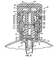
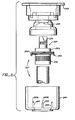
- FIGS 5, 6 and 7 show an adapter 120 used to dispense the beer from container 50 through the valve assembly 52.
- the adapter 120 has a housing 122 with interior passages 124 and 126 of increasing diameter.
- a mating valve member 128 is slidably mounted in the passage 124 and has end 130 with an 0 ring seal 132 configured to engage top 98 of the valve member 88 in sealing relationship.
- the mating valve member 128 has a central bore 134 communicating with apertures 136 between flanges 138 and 140.
- the flanges 138 and 140 engage interior surface 142 of the passage 124 in sealing relationship.
- Tapped openings 144 and 146 extend from exterior surface 148 of the housing 122 to interior surface 142 of passage 124.
- Groove 150 is configured and positioned to engage top 74 of the valve assembly housing 64 at ridge 152 in a bayonet type attachment when the neck 76 of the container 50 is inserted in the passage 126.
- Top 154 of the housing 122 has a laterally extending slot 156 and an aperture 157 through which projection 155 of an actuating bar 158 extends when the actuating bar 158 rests in slot 156.
- Clamp 153 engages recess 151 to hold the actuating bar in slot 156.
- the actuating bar 158 is pivotally attached at 160 to housing 122 on the other side of the housing 122 from the recess 151.
- Projection 155 of the actuating bar 158 engages top 162 of the mating valve member 128 before clamp 153 reaches the recess 151. Additional downward movement of the actuating bar 158 pushes downward on the mating valve member 128 to move mating valve member 128 and valve member 88 downward so that ridge 161 bottoms out on castellations 163 of ridge 104 before the clamp 153 engages recess 151. Further downward movement of the actuating bar squeezes the mating valve member 128 and the valve member 88 together to form a positive seal at 0 ring 132, which is maintained when the clamp 153 engages the recess 151. This is necessary because the seal at the 0 ring 132 must be capable of withstanding pressures of at least about 40 psi without leaking when C0 2 gas enters through tapped opening 144.
- the adapter 120 is placed over neck 76 of the container 50 with the actuating rod 158 in the position shown in Figure 5, i.e., with the engaging valve member 128 in its upward position.
- a source of pressurized carbon dioxide, air, or other suitable gas is connected to the threaded opening 144, and a beer tap is connected to the threaded opening 146.
- Actuating bar 158 is then moved downward into slot 156 and locked in the downward position in recess 151.
- Mating valve member 128 is moved down by the actuating bar 158 to the position shown in Figure 6, thus moving valve member 88 downward to open valve 52, giving flow path 166 for pressurizing gas through the opening 144 and into the container 50, and flow path 168 from the container 50 through the valve member 88 and the valve member 128 to the beer tap.
- the beer tap may then be opened to dispense the beer, with which the container 50 was filled in the manner described above with respect to Figure 3, from the container 50 as desired.
- the valve assembly 52 is therefore used both to fill the container 50 with beer and to dispense the beer in a novel manner.
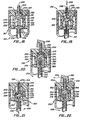
- FIGS 8, 9 and 10 show another valve assembly 180 in accordance with the invention.
- Cylindrical portion 182 of the housing 184 is similar to the cylindrical portion 66 in the Figures 2-4 embodiment, but slots 186 in interior surface 188 of the cylindrical portion 182 extend upward a greater extent than the corresponding slots 86 in the Figures 2-4 embodiment.
- Flanges 190, 192 and 194 are also differently shaped than the corresponding flanges 92, 94 and 96 in the Figures 2-4 embodiment.
- a Mylar or other flexible plastic inner container 195 is attached to fitting 197 of housing bottom 199 in place of the syphon tube 70 in the Figures 1-4 embodiment.
- valve member 196 is depressed to the position shown in Figure 9 to fill the inner container 195 with beer.
- the valve assembly 180 operates in the same manner as the valve assembly 52 of Figures 2-4, in that the beer enters the container 195 through flow path 198, and air leaves the container 50 as inner container 195 expands during the filling operation via flow path 200.
- the valve member 192 is moved to the position shown in Figure 10, thus blocking the flow path 200, while leaving the flow path 198 open.
- the container 195 expands to hold the beer and occupies most of the container 50 and an elevated pressure is created in head space 202 of the container 50.
- the valve member 196 When the container 195 is full, the valve member 196 is returned to the position shown in Figure 8.
- the pressure in the head space 202 provides pressure for initial dispensing of the beer.
- an air pump can be used with the adapter 120 of Figures 5-7 to provide additional air to the container 50 through the valve assembly 180 in the same manner as in Figure 6.
- the inner container 195 holding the beer isolates it from the air, thus preventing the air from oxidizing the beer.
- beer With the package incorporating the valve assembly 180, beer can be stored for long periods after dispensing has begun without deterioration due to air used to pressurize the container 50 for dispensing.
- the construction and operation of the Figures 8-10 embodiment is the same as the Figures 1-4 embodiment.
- FIGS 11-15 show another valve assembly 227 having upper and lower projections 229 and 231 (Figure 12) mounted on valve housing 233 interior surface 235 and engaging valve member 237 to seal fluid flow paths 239 and 241 ( Figures 14 and 15).
- the valve housing 233 consists of two pieces 243 and 245 spin welded or bonded together at 247.
- the valve member 237 includes a tube 249 extending downward beyond the valve housing 233.
- Valve member 237 has upper and lower grooves 251 and 253.
- Valve housing 233 has opening 255 and vertically disposed passages 257.
- the projections 229 and 231, valve member 237, grooves 251 and 253, opening 255 and passages 257 coact to define the fluid flow paths 239 and 241.
- the rounded shape of projection 229, interior surface 235 and portion 237a of the valve member 237 reduces agitation of the beer in the flow path 241.
- Intermediate projections 259 integrally formed on valve member 237 engage surface 235 to isolate the fluid flow paths 239 and 241 from each other.
- the valve housing 233 is spin welded or bonded to container 223 at 261.
- Leaf springs 263 are integrally molded as part of the piece 245 and bias the valve member 237 upward to keep the valve assembly 227 in a normally closed position.
- the straight configuration of the leaf springs 263 allows them to be easily molded as part of a single step molding operation used to form the piece 245.
- Tapered tips 263a cause the leaf springs 263 to be biased in a given direction as they engage the valve member 237 when the valve member 237 is moved downward toward the leaf springs 263.
- Projections 265 on the tube 249 of the valve member 237 lock the valve assembly 227 in an open position by engaging the bottom of piece 243, as shown in Figure 14, when the valve assembly 227 is fully opened to dispense beer from flow path 241.
- Projections 265 are alao integrally formed as part of the valve member 237 in the single molding step used to form the valve member 237.
- Central fin-shaped portion 267 of the valve member 237 extends upward from opening 255 of the valve housing 233.
- valve member 237 In operation, the valve member 237 is moved from its normally closed position as shown in Figure 12 to the position shown in Figure 14 to fill the container 223 with beer. The valve member 237 is not moved down far enough in this operation for the projections 265 to lock beneath the piece 243. The leaf springs 263 are bowed to a greater extent than shown in Figure 13 when the valve member is in this position. The beer enters the container 223 through the flow path 241 and air in the container 223 is vented during the filling operation through the flow path 239. When the container 223 has been filled, downward force on the valve member 237 is released, and the valve member 237 returns to the position shown in Figure 12 for shipment of the filled container 223.
- an adapter (not shown) similar to the adapter 120 of Figures 5-7 is attached to the valve assembly 227 and a source of pressurized C0 2 or air and a beer tap are connected to the adapter.
- a commercially available Sankey type tap-grabber available from Johnson Enterprises, Inc., Rockford, Illinois 61107 as item no. BJ-100 may be employed, and the valve assembly 227 is configured to engage this part.
- Valve member 237 is then fully depressed to the position shown in Figure 15 so that projections 265 move beneath piece 243 to lock the valve assembly 227 in its fully opened position for dispensing the beer from the container 223 via flow path 241.
- the leaf springs 263 are bowed to an even greater extent than in the position of Figure 14 when the valve member 237 is in this position.
- the C0 2 or air enters the container 223 via the flow path 239 to discharge the beer from the container 223.
- the adapter is removed from the valve assembly, but the projections 265 keep the valve assembly 227 locked in its open position. Locking the valve assembly 227 in the open position after the container 223 is empty provides an important safety feature in that pressure is not allowed to build up in the container 223, for example, when the container 223 is crushed for recycling.
- FIGS 16 and 17 show another valve assembly 204 in accordance with the invention.
- a top view of the valve assembly 227 of Figures 11-16 would be virtually identical in configuration to Figure 17.
- the valve assembly 204 has a valve housing 205 and a valve member 206.
- the valve housing is formed from two pieces 207 and 208, which are screwed together with threads 209, in order to allow the configuration of the housing 205 to be formed more easily by a plastic molding process.
- Upper and lower circumferential projections 211 and 213 on valve member 206 extend between the valve member 206 and the valve housing 205 and engage inside surface 215 of the valve housing 205 when the valve assembly 204 is in its closed position.
- quad ring 217 extends between the valve housing 206 and the valve member 205 in sealing engagement against inside surface 215 to isolate fluid flow paths 219 and 221 created by the valve housing 205 and the valve member 206.
- Spring 225 biases the valve member 206 upward, so that the valve assembly 204 is normally closed, with the fluid flow paths 219 and 221 sealed by the upper and lower projections 211 and 213, respectively.
- valve member 206 In operation of the valve assembly 204, the fluid flow paths 219 and 221 are bidirectional, as in the Figures 11-16 embodiment.
- valve member 206 For filling container 223 in which the valve assembly 204 is installed-, valve member 206 is displaced from its normally closed position to the position shown, opening both fluid flow paths 219 and 221. With the valve member 206 in this position, beer flows into the container 223 downward through the fluid flow path 219. At the same time, air in the container 223 is displaced upward through the fluid flow path 221. At the conclusion of filling, the valve member 206 is allowed to return to its normally closed position.
- a Sankey type tap - grabber or other adapter head (not shown), similar to the adapter head 120 ( Figures 5-7) is attached to the valve assembly 204, and the combination is operated in the same manner as the combination shown in Figures 5-7.
- the beer is discharged upward through the fluid flow path 219 and carbon dioxide, air or other pressurized gas is supplied to the container 223 downward through the fluid flow path 221 to force the beer out of the container 223.
- the substantially straight configuration of the fluid flow path 219 as in the Figure 11-14 embodiment, provides a minimum of agitation of the beer during both the filling and discharging operations.
- the construction and operation of the Figures 16-17 embodiment is the same as that of the Figures 11-15 embodiment.
- FIGS 18 and 19 show another valve assembly 210 in accordance with the invention, particularly adapted for use with a small polyethylene terapthalate (PET) aerosol container 212.
- the valve assembly 210 has a housing 214 dimensioned to fit in sealing engagement with neck 216 of the container 212.
- the housing 214 and neck 216 form an annular chamber 218 between them.
- Upper and lower passages 220 and 222 communicate between the annular chamber 218 and axial bore 224 in housing 214.
- Valve member 226 is slidably positioned within the bore. 224 with its flanges 228 and 230 in sealing engagement against inside surface 232 of the bore 224.
- Flange 234 attaches tube 236 to the housing 214 and has an axial passage 238.
- Axial passage 240 in the valve member 226 communicates with openings 242 between the flanges 228 and 230.
- Compressed spring 244 between the flange 234 and the valve member 226 urges the valve member 226 upward in the bore 224 to the position shown in Figure 18, to keep the valve assembly 210 in a normally closed state.
- valve member 226 To fill the container 212, a downward force, as indicated at 246, is applied to the valve member 226 to move it to the position shown in Figure 19. A liquid and a suitable propellant is then introduced through flow path 248 into the container 212, and the force 246 is removed, allowing the valve member 226 to return to the normally closed position shown in Figure 18. When it is desired to dispense the liquid and propellant as an aerosol spray, the valve member 226 is again depressed to the position shown in Figure 19. As the liquid and propellant leave the package 212 through the reversed flow path 248, flow through the passages 220 and 222 and the annular chamber 218 mixes the liquid and gaseous propellant thoroughly prior to their exit from the valve assembly 210.
- FIGS 20, 21, and 22 show another valve assembly 250, which will provide a metered dose of a spray 252.
- the valve assembly 250 includes a housing 254 sealed into neck 256 of container 258 to form an annular chamber 260, similar to the annular chamber 218 in Figures 18-19.
- Upper and lower passages 262 and 264 communicate between the annular chamber 260 and axial bore 266 in the housing 254.
- Valve member 268 is slidably positioned in the axial bore 266 with flanges 270, 272 and 274 in sealing engagement against inside surface 276 of the axial bore 266.
- Slots 278 extend downward below the lower passages 264 toward flange 280 in the lower end of the axial bore 266.
- Axial bore 282 in the valve member 268 communicates with apertures 284 between the flanges 270 and 272 of the valve member 268.
- valve member 268 To fill the package 258, the valve member 268 is moved to the position shown in Figure 21 prior to attachment of the spray cap 286. With the valve member 268 in this position, the liquid and a suitable gas propellant flow into the package 258 through flow path 288.
- the flow path 288 includes the axial bore 282, apertures 284, slots 278, axial bore 290 in flange 280, and tube 292.
- the valve member 268 is returned to the position shown in Figure 20, and the spray cap 286 is attached to the distal end of the axial bore 282.
- the annular chamber 260 is in communication with the pressurized liquid and propellant in the package 258, so that a quantity of the liquid and propellant, determined by the pressure in the package 258 and the volume of the chamber 260, is present in the chamber 260.
- FIG 22 shows the valve assembly 250 with the valve member 268 in dispensing position.
- the lowest flange 274 on the valve member 268 rests between the lower passages 264 and the top of slots 278.
- the annular chamber 260 is therefore not in communication with the liquid and propellant in the remainder of the package 258 at the time that the discharge of spray 252 takes place.
- the spray cap 286 bottoms out on surface 294 of the housing 254 to prevent the flange 274 from reaching the slots 278.
- a premeasured dose of the spray 252 is then discharged from the annular chamber 260 through the upper passages 262, apertures 284, axial bore 282 and the spray cap 286.
- valve member 268 When downward pressure on the spray cap 286 it released, the valve member 268 returns to the position shown in Figure 20. Once again, the annular chamber 260 is in communication with the liquid and propellant in the remainder of the package 258 through the lower passages 264, and a measured dose of the liquid and propellant again enters the annular chamber 260 from the rest of the package 258.
- FIGS 23-26 show another valve assembly 300 in accordance with the invention, for use with a large PET container 302.
- the assembly 300 is similar to the assembly 210 in Figures 18 and 19, but modified to fit in the container 302.
- a generally cup shaped housing 304 is spin welded or ultrasonically bonded at lip 306 to neck 308 of the container 302 and extends downward into the container.
- Projection 310 having axial bore 312 engages tube 314.
- Insert 316 extends into the housing 304 to define an annular chamber 318.
- Top 320 integrally formed as part of the insert 316 extends over the housing 304 and is also spin welded or ultrasonically bonded to the neck 308 at 322.
- Valve member 330 is slidably mounted in interior 328 of insert 316, with flanges 332 and 334 in sealing engagement against interior surface 336 of the insert 316.
- Projection 338 of valve member 330 extends through opening 340 in top 320 and has an axial bore 342 communicating with apertures 344 between the flanges 332 and 334 of the insert 330.
- Compressed spring 346 between the housing 304 and the valve member 33P biases the valve member 330 upward to the position shown in Figure 23.
- valve member 330 In operation, when the valve member 330 is pushed downward so that apertures 344 are communication with the upper passages 324, liquid and propellant under pressure in the container 302 is discharged from the container 302 in a discharge path including the bore 312, interior 328, passage 326, annular chamber 318, passages 324, apertures 34-4 and bore 342.
- the triangular shape of the passages 324 allows the size of the flow path to increase as the flange 344 passes over them, thus allowing the flow rate of the aerosol spray to be modulated.
- the annular chamber 318 assures thorough mixing of the liquid and propellant in the discharge flow path before they leave the package.
- Figures 25 and 26 show alternative forms of inserts 348 and 350, which may be substituted for the insert 316 shown in Figures 23 and 24.
- the insert 348 has its apertures 352 extending in an inclined pattern around the insert 348. This means that, as the valve member 330 ( Figures 23 and 24) is moved downward within the interior 328 a greater extent, a larger number of the apertures 352 are positioned between flanges 332 and 334 of the valve member 330. As the number of apertures 352 between the flanges 332 and 334 is increased, a larger flow path is defined, thus allowing the discharge rate of liquid and propellant from the container 302 to be increased.
- the construction and operation of a valve assembly including the insert 348 is the same as in the Figures 23 and 24 embodiment.
- the insert 350 has the separate passages 324 and 326 of the insert 316 ( Figures 23 and 24) replaced with inclined slots 354.
- lower flange 334 of the insert 330 divides the slots 354 into two portions, with the relative size of the portions depending on the position of the valve member 330 in interior 328.
- the flow path of the liquid and propellant from the container 302 is largest, with the correspondingly largest flow rate of discharge.
- FIG 27 shows another valve assembly 360 in accordance with the invention, which is configured to fit inside an industry standard aerosol cup 362, so that the valve assembly 360 may be used in a standard metal aerosol spray can 364.
- the internal construction of the valve assembly 360 is the same as the valve assembly 300 shown in Figures 23 and 24, but top 366 is configured with a rounded edge 368 to accommodate rolled metal sleeve 370 of the aerosol cup 362.
- the external configuration of the valve assembly 360 is thus identical to the external configuration of conventional Abplanalp valves employed in these aerosol packages, but the valve assembly 360 has the flow rate regulation characteristics of the Figures 23-24 embodiment.
- inserts having the aperture configurations of the Figures 25 and 26 inserts 348 and 350, but modified at their top in the same manner as the top 366 in Figure 27, could be employed in the valve assembly 360.
- valve assemblies described are advantageously fabricated from a suitable molded plastic material.
- a suitable molded plastic material for this purpose, an injection molded co-polyester plastic is preferably employed.
- Such plastic parts give a low cost, easily manufactured valve assembly.
- The'valve.assembly is configured so that it can be adapted to meet a variety of specific requirements in the packaging of pressurized liquids, from draft beer packaging to aerosol spray containers.
- Multiple flow paths and related configurations employed in the valve assembly allow both filling. and dispensing of pressurized liquids through the valves, thus
- An improved draft beer container using the valve assembly allows air to be introduced to the container through the valve assembly and not contact draft beer in the container, thus allowing air to be used to pressurize the container without oxidizing the beer.
- the valve assembly and adapter fills a draft beer container, pressurizes the container and dispenses the draft beer in an improved manner and incorporates a positive seal between the valve assembly and the adapter.
- the valve assembly provides a flow path for the beer that minimizes agitation and incorporates a lock open feature to prevent dangerous pressures when the empty container is crushed.
- the configuration of the valve assembly allows it to be easily fabricated by molding, such as of plastic.
- the valve assembly also allows regulation of pressurized liquid flow rate and improved mixing of an aerosol spray.
Abstract
Description
- As the need to simplify and reduce packaging costs of such different liquid products as draft beer and aerosol sprays has become increasingly severe, producers of these products have begun to consider alternatives to traditional metal or glass containers. The development of the so-called "Beer Sphere" and the consideration of plastic packaging for aerosol spray products are representative of these trends. While packaging technology for liquids is thus undergoing a period of rapid change and development, valve design has not kept pace. To a certain extent, conventional valve designs can be adapted for new container technologies, but this results in unnecessary difficulty and expense.
- With respect to beer valve technology, representative prior art includes the following patents to Johnston: U.S. 3,861,569, issued January 21, 1975; U.S. 3,866,626, issued February 18, 1975 and U.S. 3,868,049, issued February 25, 1975.
- With respect to aerosol spray and related packaging technology, representative prior art includes the following U.S. patents: U.S. 2,500,119, issued March 7, 1950 to Cooper; U.S. 2,543,850, issued March 6, 1951 to Henricson; U.S. 2,631,814 and U.S. 2,799,435, issued March 17, 1953 and July 16, 1957, respectively, to Abplanalp; U.S. 2,863,699, issued December 9, 1958 to Elser; U.S. 2,913,749, issued November 24, 1959 to Ayres; U.S. 3,333,743, issued August 1, 1967 to Meyers; U.S. 3,348,742, issued October 24, 1967 to Assalit; and U.S. 3,863,673, issued February 4, 1975 to Sitton. Other prior art references describing such valves and packages include French patent application 2,462,629, published February 13, 1981; European patent application 97,094, published December 28, 1983 and French patent application 2,382,946, published October 6, 1978.
- The state of the art in liquid packaging technology is further indicated by Proceedings of Ryder Conference, 1985; Ninth International Conference on Oriented Plastic Containers, presented on March 25-27, 1985, C. E. Sroog, R. J. Albert, F. P. Gay, and S. J. Seckner, "PET Aerosols Technology and Applications," pages 245-28. While the art relating to the packaging and dispensing of liquids is therefore a well developed one, a need still remains for further development of valve designs to meet the demands of newer packaging technology for liquids.
- The present invention provides a valve assembly, which comprises an insert dimensioned and configured to fit in a necked opening of a container, said insert defining a valve housing, a valve member slideably mounted in said valve housing, said valve housing having a plurality of apertures located along a path of travel of said valve member in said valve housing, the apertures extending through the housing to an interior surface thereof, said valve member and said valve housing having a plurality of projections spaced along a length of said valve member and said valve housing extending between the interior surface of said valve housing and said valve member in sealing relationship, the projections, valve housing interior surface, apertures and valve member coacting to provide a flow path through said valve when the valve member is in a first position and to seal the flow path when the valve member is in a second position, and means biasing said valve member to the second position.
- By way of example, embodiments of the invention will now be described with reference to the accompanying drawings, in which:
- Figure 1 is a perspective and diagrammatic view useful for understanding certain embodiments of the invention.
- Figure 2 is a cross-section view of a valve assembly in accordance with the invention.
- Figure 3 is another cross-section view of the valve assembly in Figure 2, but with the valve in operation.
- Figure 4 is an exploded perspective view of the valve assembly in Figures 2 and 3.
- Figure 5 is a perspective and cross-section view of apparatus further showing use of the valve assembly embodiment of Figures 2-4.
- Figure 6 is another cross-section of the apparatus shown in Figure 5, but in a different operating position.
- Figure 7 is an exploded perspective view of the apparatus shown in Figures 5 and 6.
- Figure 8 is a cross-section view of a second valve assembly in accordance with the invention.
- Figures 9 and 10 are further cross-section views of the valve assembly in Figure 8, but in different stages of operation.
- Figure 11 is an exploded side view of a third valve assembly in accordance with the invention.
- Figure 12 is a schematic cross-section view of the valve assembly shown in Figure 11.
- Figure 13 is a perspective and partial cross-section view of a portion of the valve assembly shown in Figures 11 and 12.
- Figure 14 is another schematic cross-section view of the valve assembly in Figure 12, but in a different stage of operation.
- Figure 15 is another cross-section view of the valve assembly in Figures 12, 13 and 14, but in still another stage of operation.
- Figure 16 is a schematic cross-section view of a fourth valve assembly in accordance with the invention.
- Figure 17 is a top view of the valve assembly shown in Figure 16.
- Figure 18 is a schematic cross-section view of a fifth valve assembly in accordance with the invention.
- Figure 19 is another schematic cross-section view of the valve assembly in Figure 18, but during operation.
- Figure 20 is a schematic cross-section view of a sixth valve assembly in accordance with the invention.
- Figures 21 and 22 are additional schematic cross-section views of the valve assembly in Figure 20, but in different stages of operation.
- Figure 23 is a schematic cross-section view of a seventh valve assembly in accordance with the invention.
- Figure 24 is an exploded side view of the valve assembly shown in Figure 23.
- Figures 25 and 26 are side views of alternative embodiments of a portion of the valve assembly shown in Figures 23 and 24.
- Figure 27 is a cross-section view of a sixth valve assembly in accordance with the invention.
- In Figure 1 there is shown a
container 50 for draft beer, incorporating avalve assembly 52 in accordance with the invention. As indicated at 54 and 56, thevalve assembly 52 is used both for filling thecontainer 50 with the draft beer and for dispensing the beer from thecontainer 50. - Figures 2, 3 and 4 show the
valve assembly 52 in more detail. Thevalve assembly 52 has avalve housing 64, consisting of a generallycylindrical portion 66 and asyphon tube flange 68 attached to thecylindrical portion 66, such as by ultrasonic bonding or spin welding. Asyphon tube 70 is attached to thesyphon tube flange 68. - If desired, the
syphon tube 70 andflange 68 may be integrally formed. - The
cylindrical portion 66 has a flange 72 aroundtop 74, by which thecylindrical portion 66 is sealed toneck 76 of thecontainer 50, such as by ultrasonic bonding or spin welding. Top 74 of theportion 66 has acircular opening 78. A first set ofapertures 80 extends fromexterior surface 82 of theportion 66 to itsinterior surface 84 near thetop 74. A set ofgrooves 86 extends vertically along theinside surface 84 of theportion 66 just above thesyphon tube flange 68. - Valve
member 88 is slidably movable inside thevalve housing 64 between thetop 74 and thesyphon tube flange 68. Thevalve member 88 has acylindrical body 90 andflanges inside surface 84 of thecylindrical portion 66 in sealing relationship. Anupper portion 98 of reduced diameter extends through the opening 78 intop 74 of thehousing 64.Top portion 98 has a plurality ofslots 100 to allow air to escape through theopening 78 when thevalve member 88 is pushed away from thetop 74 of the housing 64 (see Figure 3). - A
spring 102 urges thevalve member 88 against thetop 74 of thehousing 64 to keep thevalve assembly 52 in a normally closed position.Mating projections 104 and 161 (best shown in Figures 5 and 6) on thesyphon tube flange 68 and thevalve member 88, respectively, hold thespring 102 in position. Thevalve member 88 has a centrally disposedbore 108 extending downward toapertures 110 between theflanges - To use the
valve assembly 52 for filling thecontainer 50, thevalve member 88 is displaced downward to the position shown in Figure 3. This opens a flow path for beer used to fill thecontainer 50, indicated at 112, through thebore 108,apertures 110,grooves 86 andtube 70. A second flow path indicated at 114 is opened betweenneck 76 of thecontainer 50,portion 66 of thehousing 64, throughapertures 80, betweenhousing top 74 andtop 98 of thevalve member 88. As thecontainer 50 fills with the beer throughflow path 112, air is exhausted from thecontainer 50 through theflow path 114. When thecontainer 50 is filled with beer, downward force on thevalve member 88 is removed, so thatspring 102 will return thevalve member 88 to the position shown in Figure 2, withsurface 118 of thevalve member 88 in sealing relationship againsttop 74 of thehousing 64. Carbonation pressure from the beer further serves to urge thesurface 118 againsttop 74. - Figures 5, 6 and 7 show an
adapter 120 used to dispense the beer fromcontainer 50 through thevalve assembly 52. Theadapter 120 has ahousing 122 withinterior passages mating valve member 128 is slidably mounted in thepassage 124 and hasend 130 with an 0ring seal 132 configured to engage top 98 of thevalve member 88 in sealing relationship. Themating valve member 128 has acentral bore 134 communicating withapertures 136 betweenflanges flanges interior surface 142 of thepassage 124 in sealing relationship. Tappedopenings exterior surface 148 of thehousing 122 tointerior surface 142 ofpassage 124.Groove 150 is configured and positioned to engage top 74 of thevalve assembly housing 64 atridge 152 in a bayonet type attachment when theneck 76 of thecontainer 50 is inserted in thepassage 126.Top 154 of thehousing 122 has a laterally extendingslot 156 and anaperture 157 through whichprojection 155 of anactuating bar 158 extends when theactuating bar 158 rests inslot 156.Clamp 153 engagesrecess 151 to hold the actuating bar inslot 156. Theactuating bar 158 is pivotally attached at 160 tohousing 122 on the other side of thehousing 122 from therecess 151.Projection 155 of theactuating bar 158 engages top 162 of themating valve member 128 beforeclamp 153 reaches therecess 151. Additional downward movement of theactuating bar 158 pushes downward on themating valve member 128 to movemating valve member 128 andvalve member 88 downward so thatridge 161 bottoms out oncastellations 163 ofridge 104 before theclamp 153 engagesrecess 151. Further downward movement of the actuating bar squeezes themating valve member 128 and thevalve member 88 together to form a positive seal at 0ring 132, which is maintained when theclamp 153 engages therecess 151. This is necessary because the seal at the 0ring 132 must be capable of withstanding pressures of at least about 40 psi without leaking when C02 gas enters through tappedopening 144. - In operation, the
adapter 120 is placed overneck 76 of thecontainer 50 with theactuating rod 158 in the position shown in Figure 5, i.e., with the engagingvalve member 128 in its upward position. A source of pressurized carbon dioxide, air, or other suitable gas is connected to the threadedopening 144, and a beer tap is connected to the threadedopening 146. Actuatingbar 158 is then moved downward intoslot 156 and locked in the downward position inrecess 151.Mating valve member 128 is moved down by theactuating bar 158 to the position shown in Figure 6, thus movingvalve member 88 downward to openvalve 52, givingflow path 166 for pressurizing gas through theopening 144 and into thecontainer 50, and flowpath 168 from thecontainer 50 through thevalve member 88 and thevalve member 128 to the beer tap. The beer tap may then be opened to dispense the beer, with which thecontainer 50 was filled in the manner described above with respect to Figure 3, from thecontainer 50 as desired. Thevalve assembly 52 is therefore used both to fill thecontainer 50 with beer and to dispense the beer in a novel manner. - Figures 8, 9 and 10 show another
valve assembly 180 in accordance with the invention.Cylindrical portion 182 of thehousing 184 is similar to thecylindrical portion 66 in the Figures 2-4 embodiment, butslots 186 ininterior surface 188 of thecylindrical portion 182 extend upward a greater extent than the correspondingslots 86 in the Figures 2-4 embodiment.Flanges flanges inner container 195 is attached to fitting 197 ofhousing bottom 199 in place of thesyphon tube 70 in the Figures 1-4 embodiment. In use of the Figures 8-10 embodiment,valve member 196 is depressed to the position shown in Figure 9 to fill theinner container 195 with beer. For most of the filling operation, thevalve assembly 180 operates in the same manner as thevalve assembly 52 of Figures 2-4, in that the beer enters thecontainer 195 throughflow path 198, and air leaves thecontainer 50 asinner container 195 expands during the filling operation viaflow path 200. However, when thecontainer 195 is nearly full, thevalve member 192 is moved to the position shown in Figure 10, thus blocking theflow path 200, while leaving theflow path 198 open. As thecontainer 195 is filled with additional beer, thecontainer 195 expands to hold the beer and occupies most of thecontainer 50 and an elevated pressure is created in head space 202 of thecontainer 50. When thecontainer 195 is full, thevalve member 196 is returned to the position shown in Figure 8. The pressure in the head space 202 provides pressure for initial dispensing of the beer. As this pressure is depleted, an air pump can be used with theadapter 120 of Figures 5-7 to provide additional air to thecontainer 50 through thevalve assembly 180 in the same manner as in Figure 6. Theinner container 195 holding the beer isolates it from the air, thus preventing the air from oxidizing the beer. With the package incorporating thevalve assembly 180, beer can be stored for long periods after dispensing has begun without deterioration due to air used to pressurize thecontainer 50 for dispensing. In other respects than as shown and described, the construction and operation of the Figures 8-10 embodiment is the same as the Figures 1-4 embodiment. - Figures 11-15 show another
valve assembly 227 having upper andlower projections 229 and 231 (Figure 12) mounted onvalve housing 233interior surface 235 and engagingvalve member 237 to sealfluid flow paths 239 and 241 (Figures 14 and 15). For ease of molding, thevalve housing 233 consists of twopieces valve member 237 includes atube 249 extending downward beyond thevalve housing 233.Valve member 237 has upper andlower grooves Valve housing 233 hasopening 255 and vertically disposedpassages 257. Theprojections valve member 237,grooves passages 257 coact to define thefluid flow paths projection 229,interior surface 235 and portion 237a of thevalve member 237 reduces agitation of the beer in theflow path 241.Intermediate projections 259 integrally formed onvalve member 237 engagesurface 235 to isolate thefluid flow paths valve housing 233 is spin welded or bonded tocontainer 223 at 261. Leaf springs 263 are integrally molded as part of thepiece 245 and bias thevalve member 237 upward to keep thevalve assembly 227 in a normally closed position. The straight configuration of theleaf springs 263 allows them to be easily molded as part of a single step molding operation used to form thepiece 245.Tapered tips 263a cause theleaf springs 263 to be biased in a given direction as they engage thevalve member 237 when thevalve member 237 is moved downward toward the leaf springs 263.Projections 265 on thetube 249 of thevalve member 237 lock thevalve assembly 227 in an open position by engaging the bottom ofpiece 243, as shown in Figure 14, when thevalve assembly 227 is fully opened to dispense beer fromflow path 241.Projections 265 are alao integrally formed as part of thevalve member 237 in the single molding step used to form thevalve member 237. Central fin-shapedportion 267 of thevalve member 237 extends upward from opening 255 of thevalve housing 233. When thevalve assembly 227 is put together, the leaf springs are bowed slightly, as is best shown in Figure 13, in order to preload thevalve member 237 with sufficient force to keep thevalve assembly 227 normally closed.Syphon tube 269 is spin welded or bonded at 271 inside thetube portion 249 of thevalve member 237. - In operation, the
valve member 237 is moved from its normally closed position as shown in Figure 12 to the position shown in Figure 14 to fill thecontainer 223 with beer. Thevalve member 237 is not moved down far enough in this operation for theprojections 265 to lock beneath thepiece 243. The leaf springs 263 are bowed to a greater extent than shown in Figure 13 when the valve member is in this position. The beer enters thecontainer 223 through theflow path 241 and air in thecontainer 223 is vented during the filling operation through theflow path 239. When thecontainer 223 has been filled, downward force on thevalve member 237 is released, and thevalve member 237 returns to the position shown in Figure 12 for shipment of the filledcontainer 223. To dispense the beer from thecontainer 223, an adapter (not shown) similar to theadapter 120 of Figures 5-7 is attached to thevalve assembly 227 and a source of pressurized C02 or air and a beer tap are connected to the adapter. For this purpose, a commercially available Sankey type tap-grabber, available from Johnson Enterprises, Inc., Rockford, Illinois 61107 as item no. BJ-100 may be employed, and thevalve assembly 227 is configured to engage this part.Valve member 237 is then fully depressed to the position shown in Figure 15 so thatprojections 265 move beneathpiece 243 to lock thevalve assembly 227 in its fully opened position for dispensing the beer from thecontainer 223 viaflow path 241. The leaf springs 263 are bowed to an even greater extent than in the position of Figure 14 when thevalve member 237 is in this position. The C02 or air enters thecontainer 223 via theflow path 239 to discharge the beer from thecontainer 223. When thecontainer 223 is empty, the adapter is removed from the valve assembly, but theprojections 265 keep thevalve assembly 227 locked in its open position. Locking thevalve assembly 227 in the open position after thecontainer 223 is empty provides an important safety feature in that pressure is not allowed to build up in thecontainer 223, for example, when thecontainer 223 is crushed for recycling. - Figures 16 and 17 show another
valve assembly 204 in accordance with the invention. A top view of thevalve assembly 227 of Figures 11-16 would be virtually identical in configuration to Figure 17. Thevalve assembly 204 has avalve housing 205 and avalve member 206. The valve housing is formed from twopieces threads 209, in order to allow the configuration of thehousing 205 to be formed more easily by a plastic molding process. Upper and lowercircumferential projections valve member 206 extend between thevalve member 206 and thevalve housing 205 and engage insidesurface 215 of thevalve housing 205 when thevalve assembly 204 is in its closed position. Similarly,quad ring 217 extends between thevalve housing 206 and thevalve member 205 in sealing engagement againstinside surface 215 to isolatefluid flow paths valve housing 205 and thevalve member 206.Spring 225 biases thevalve member 206 upward, so that thevalve assembly 204 is normally closed, with thefluid flow paths lower projections - In operation of the
valve assembly 204, thefluid flow paths container 223 in which thevalve assembly 204 is installed-,valve member 206 is displaced from its normally closed position to the position shown, opening bothfluid flow paths valve member 206 in this position, beer flows into thecontainer 223 downward through thefluid flow path 219. At the same time, air in thecontainer 223 is displaced upward through thefluid flow path 221. At the conclusion of filling, thevalve member 206 is allowed to return to its normally closed position. - When it is desired to discharge the beer from the
container 223, a Sankey type tap-grabber or other adapter head (not shown), similar to the adapter head 120 (Figures 5-7) is attached to thevalve assembly 204, and the combination is operated in the same manner as the combination shown in Figures 5-7. The beer is discharged upward through thefluid flow path 219 and carbon dioxide, air or other pressurized gas is supplied to thecontainer 223 downward through thefluid flow path 221 to force the beer out of thecontainer 223. The substantially straight configuration of thefluid flow path 219, as in the Figure 11-14 embodiment, provides a minimum of agitation of the beer during both the filling and discharging operations. Other than as shown and described, the construction and operation of the Figures 16-17 embodiment is the same as that of the Figures 11-15 embodiment. - Figures 18 and 19 show another
valve assembly 210 in accordance with the invention, particularly adapted for use with a small polyethylene terapthalate (PET)aerosol container 212. Thevalve assembly 210 has a housing 214 dimensioned to fit in sealing engagement withneck 216 of thecontainer 212. The housing 214 andneck 216 form anannular chamber 218 between them. Upper andlower passages annular chamber 218 andaxial bore 224 in housing 214.Valve member 226 is slidably positioned within the bore. 224 with itsflanges inside surface 232 of thebore 224.Flange 234 attachestube 236 to the housing 214 and has anaxial passage 238.Axial passage 240 in thevalve member 226 communicates with openings 242 between theflanges Compressed spring 244 between theflange 234 and thevalve member 226 urges thevalve member 226 upward in thebore 224 to the position shown in Figure 18, to keep thevalve assembly 210 in a normally closed state. - To fill the
container 212, a downward force, as indicated at 246, is applied to thevalve member 226 to move it to the position shown in Figure 19. A liquid and a suitable propellant is then introduced throughflow path 248 into thecontainer 212, and theforce 246 is removed, allowing thevalve member 226 to return to the normally closed position shown in Figure 18. When it is desired to dispense the liquid and propellant as an aerosol spray, thevalve member 226 is again depressed to the position shown in Figure 19. As the liquid and propellant leave thepackage 212 through the reversedflow path 248, flow through thepassages annular chamber 218 mixes the liquid and gaseous propellant thoroughly prior to their exit from thevalve assembly 210. - Figures 20, 21, and 22 show another
valve assembly 250, which will provide a metered dose of aspray 252. Thevalve assembly 250 includes ahousing 254 sealed intoneck 256 ofcontainer 258 to form anannular chamber 260, similar to theannular chamber 218 in Figures 18-19. Upper andlower passages annular chamber 260 andaxial bore 266 in thehousing 254.Valve member 268 is slidably positioned in theaxial bore 266 withflanges inside surface 276 of theaxial bore 266.Slots 278 extend downward below thelower passages 264 towardflange 280 in the lower end of theaxial bore 266. Axial bore 282 in thevalve member 268 communicates withapertures 284 between theflanges valve member 268. - To fill the
package 258, thevalve member 268 is moved to the position shown in Figure 21 prior to attachment of thespray cap 286. With thevalve member 268 in this position, the liquid and a suitable gas propellant flow into thepackage 258 throughflow path 288. Theflow path 288 includes theaxial bore 282,apertures 284,slots 278,axial bore 290 inflange 280, andtube 292. When thepackage 258 has been filled, thevalve member 268 is returned to the position shown in Figure 20, and thespray cap 286 is attached to the distal end of theaxial bore 282. With thevalve member 268 in this position, theannular chamber 260 is in communication with the pressurized liquid and propellant in thepackage 258, so that a quantity of the liquid and propellant, determined by the pressure in thepackage 258 and the volume of thechamber 260, is present in thechamber 260. - Figure 22 shows the
valve assembly 250 with thevalve member 268 in dispensing position. In this position, thelowest flange 274 on thevalve member 268 rests between thelower passages 264 and the top ofslots 278. Theannular chamber 260 is therefore not in communication with the liquid and propellant in the remainder of thepackage 258 at the time that the discharge ofspray 252 takes place. Thespray cap 286 bottoms out onsurface 294 of thehousing 254 to prevent theflange 274 from reaching theslots 278. A premeasured dose of thespray 252 is then discharged from theannular chamber 260 through theupper passages 262,apertures 284,axial bore 282 and thespray cap 286. - When downward pressure on the
spray cap 286 it released, thevalve member 268 returns to the position shown in Figure 20. Once again, theannular chamber 260 is in communication with the liquid and propellant in the remainder of thepackage 258 through thelower passages 264, and a measured dose of the liquid and propellant again enters theannular chamber 260 from the rest of thepackage 258. - Figures 23-26 show another
valve assembly 300 in accordance with the invention, for use with alarge PET container 302. Theassembly 300 is similar to theassembly 210 in Figures 18 and 19, but modified to fit in thecontainer 302. A generally cup shapedhousing 304 is spin welded or ultrasonically bonded atlip 306 toneck 308 of thecontainer 302 and extends downward into the container.Projection 310 havingaxial bore 312 engagestube 314.Insert 316 extends into thehousing 304 to define anannular chamber 318. Top 320 integrally formed as part of theinsert 316 extends over thehousing 304 and is also spin welded or ultrasonically bonded to theneck 308 at 322. Upper andlower passages annular chamber 318 and interior 328 defined by theinsert 316 andhousing 304.Valve member 330 is slidably mounted ininterior 328 ofinsert 316, withflanges interior surface 336 of theinsert 316.Projection 338 ofvalve member 330 extends through opening 340 in top 320 and has anaxial bore 342 communicating withapertures 344 between theflanges insert 330.Compressed spring 346 between thehousing 304 and the valve member 33P biases thevalve member 330 upward to the position shown in Figure 23. - In operation, when the
valve member 330 is pushed downward so thatapertures 344 are communication with theupper passages 324, liquid and propellant under pressure in thecontainer 302 is discharged from thecontainer 302 in a discharge path including thebore 312, interior 328,passage 326,annular chamber 318,passages 324, apertures 34-4 and bore 342. The triangular shape of thepassages 324 allows the size of the flow path to increase as theflange 344 passes over them, thus allowing the flow rate of the aerosol spray to be modulated. Theannular chamber 318 assures thorough mixing of the liquid and propellant in the discharge flow path before they leave the package. - Figures 25 and 26 show alternative forms of
inserts insert 316 shown in Figures 23 and 24. Theinsert 348 has itsapertures 352 extending in an inclined pattern around theinsert 348. This means that, as the valve member 330 (Figures 23 and 24) is moved downward within the interior 328 a greater extent, a larger number of theapertures 352 are positioned betweenflanges valve member 330. As the number ofapertures 352 between theflanges container 302 to be increased. In other respects, the construction and operation of a valve assembly including theinsert 348 is the same as in the Figures 23 and 24 embodiment. - In Figure 26, the
insert 350 has theseparate passages inclined slots 354. With thisinsert 350,lower flange 334 of theinsert 330 divides theslots 354 into two portions, with the relative size of the portions depending on the position of thevalve member 330 ininterior 328. With thevalve member 330 midway in its path of travel, the flow path of the liquid and propellant from thecontainer 302 is largest, with the correspondingly largest flow rate of discharge. - Figure 27 shows another
valve assembly 360 in accordance with the invention, which is configured to fit inside an industrystandard aerosol cup 362, so that thevalve assembly 360 may be used in a standard metal aerosol spray can 364. The internal construction of thevalve assembly 360 is the same as thevalve assembly 300 shown in Figures 23 and 24, but top 366 is configured with arounded edge 368 to accommodate rolledmetal sleeve 370 of theaerosol cup 362. The external configuration of thevalve assembly 360 is thus identical to the external configuration of conventional Abplanalp valves employed in these aerosol packages, but thevalve assembly 360 has the flow rate regulation characteristics of the Figures 23-24 embodiment. Alternatively, inserts having the aperture configurations of the Figures 25 and 26inserts valve assembly 360. - In practice, the valve assemblies
described are advantageously fabricated from a suitable molded plastic material. For this purpose, an injection molded co-polyester plastic is preferably employed. Such plastic parts give a low cost, easily manufactured valve assembly. - . The'valve.assembly is configured
so that it can be adapted to meet a variety of specific requirements in the packaging of pressurized liquids, from draft beer packaging to aerosol spray containers. Multiple flow paths and related configurations employed in the valve assembly allow both filling. and dispensing of pressurized liquids through the valves, thus - eliminating the need for cold filling prior to insertion of the valve assembly in a package. An improved draft beer container using the valve assembly allows
air to be introduced to the container through the valve assembly and not contact draft beer in the container, thus allowing air to be used to pressurize the container without oxidizing the beer. The valve assembly and adapter fills a draft beer container, pressurizes the container and dispenses the draft beer in an improved manner and incorporates a positive seal between the valve assembly and the adapter. The valve assembly provides
a flow path for the beer that minimizes agitation and incorporates a lock open feature to prevent dangerous pressures when the empty container is crushed. The configuration of the valve assembly allows it to be easily fabricated by molding, such as of plastic. The valve assembly also allows regulation of pressurized liquid flow rate and improved mixing of an aerosol spray.
Claims (49)
Applications Claiming Priority (4)
| Application Number | Priority Date | Filing Date | Title |
|---|---|---|---|
| US79943685A | 1985-11-19 | 1985-11-19 | |
| US799436 | 1985-11-19 | ||
| US06/820,400 US4756347A (en) | 1985-11-19 | 1986-01-17 | Filling and dispensing valve, adapter and package |
| US820400 | 1986-01-17 |
Publications (2)
| Publication Number | Publication Date |
|---|---|
| EP0224380A2 true EP0224380A2 (en) | 1987-06-03 |
| EP0224380A3 EP0224380A3 (en) | 1988-08-17 |
Family
ID=27122117
Family Applications (1)
| Application Number | Title | Priority Date | Filing Date |
|---|---|---|---|
| EP19860309066 Withdrawn EP0224380A3 (en) | 1985-11-19 | 1986-11-19 | Valve assembly |
Country Status (4)
| Country | Link |
|---|---|
| US (1) | US4756347A (en) |
| EP (1) | EP0224380A3 (en) |
| AU (1) | AU6514286A (en) |
| BR (1) | BR8605684A (en) |
Cited By (8)
| Publication number | Priority date | Publication date | Assignee | Title |
|---|---|---|---|---|
| EP0298376A2 (en) * | 1987-07-02 | 1989-01-11 | Baderi, Jopado | Filling and dispensing valve with drop-away valve member |
| WO1990008729A1 (en) * | 1989-01-28 | 1990-08-09 | Joachim Mogler | Tap head for keg fittings |
| WO1995011855A1 (en) * | 1993-10-26 | 1995-05-04 | Imi Cornelius Brasil Ltda. | Container connection device, fluid dispensing assembly therefor and container provided therewith |
| US5862961A (en) * | 1993-10-26 | 1999-01-26 | Imi Cornelius Inc. | Connection device for dispensing fluid from a bottle |
| EP0911270A1 (en) * | 1997-10-22 | 1999-04-28 | Firma Benno Fell | Beverage bottle, process for manufacturing a beverage bottle, use of a beverage bottle and beverage preparation system |
| WO2000003944A1 (en) * | 1998-07-15 | 2000-01-27 | Heineken Technical Services B.V. | Valve assembly for a beverage container, container for beverage and method for filling and emptying a beverage container |
| WO2013188609A1 (en) | 2012-06-14 | 2013-12-19 | 3M Innovative Properties Company | Metered dose dispensing valve |
| IT201800010165A1 (en) * | 2018-11-08 | 2020-05-08 | Biokeg S R L | DRUM FOR EDIBLE LIQUIDS, IN PARTICULAR FOR BEER |
Families Citing this family (28)
| Publication number | Priority date | Publication date | Assignee | Title |
|---|---|---|---|---|
| CA1340347C (en) * | 1988-02-16 | 1999-01-26 | Michael L. Osgar | Container and dispensing system for liquid chemicals |
| US5102010A (en) * | 1988-02-16 | 1992-04-07 | Now Technologies, Inc. | Container and dispensing system for liquid chemicals |
| US5526956A (en) * | 1992-09-11 | 1996-06-18 | Now Technologies, Inc. | Liquid chemical dispensing and recirculating system |
| US5957328A (en) * | 1992-09-11 | 1999-09-28 | Now Technologies, Inc. | Liquid chemical dispensing and recirculating system |
| US5335821A (en) * | 1992-09-11 | 1994-08-09 | Now Technologies, Inc. | Liquid chemical container and dispensing system |
| US5597095A (en) * | 1993-06-09 | 1997-01-28 | Precision Valve Corporation | Dual arm aerosol actuator having a movable and stationary arm |
| CA2282287A1 (en) * | 1997-02-19 | 1998-08-27 | Rocep Lusol Holdings Limited | Method of producing a frothed liquid |
| US6550416B2 (en) * | 1997-04-10 | 2003-04-22 | Duncan Newman | Pneumatic valve device |
| US6817485B2 (en) | 1998-04-08 | 2004-11-16 | Aicello Chemical Co., Ltd. | Container for photoresist liquid |
| ATE299729T1 (en) * | 2001-03-15 | 2005-08-15 | Us Gov Health & Human Serv | NEBULIZER WITH COOLING CHAMBER |
| US7188644B2 (en) * | 2002-05-03 | 2007-03-13 | Advanced Technology Materials, Inc. | Apparatus and method for minimizing the generation of particles in ultrapure liquids |
| GB2414016B (en) * | 2004-03-26 | 2007-04-11 | Diageo Ireland | A valve assembly for a beverage dispenser |
| MXPA06011426A (en) * | 2004-04-02 | 2007-04-20 | Gov Health & Human Serv | Aerosol delivery systems and methods. |
| DE102006026279B4 (en) | 2006-06-02 | 2016-02-25 | Khs Gmbh | Method and device for producing packaging units or containers |
| DE102006061120B4 (en) * | 2006-12-22 | 2011-12-22 | Khs Gmbh | Keg |
| GB2446596A (en) * | 2007-02-14 | 2008-08-20 | Ineos Fluor R T & E | Biomass extraction apparatus |
| ATE480471T1 (en) * | 2007-05-30 | 2010-09-15 | Eurokeg Bv | CLOSING VALVE AND CONTAINER WITH IT |
| US8813747B2 (en) * | 2009-08-07 | 2014-08-26 | Hexbg, Llc | Vaporizer system for delivery of inhalable substances |
| GB201005994D0 (en) | 2010-04-09 | 2010-05-26 | Petainer Lidkoeping Ab | Keg closure with safety mechanism |
| US10252210B2 (en) | 2011-05-10 | 2019-04-09 | The Procter & Gamble Company | Methods for reducing particulates in the air |
| US20150014367A1 (en) * | 2013-07-10 | 2015-01-15 | Joel Michael VanSyckel | Bottle Stopper With A Dispensing Mechanism |
| DE102016013852B4 (en) | 2016-11-22 | 2018-08-16 | Fass-Frisch Gmbh | Valve insert and container |
| US10596765B2 (en) * | 2017-05-16 | 2020-03-24 | The Procter & Gamble Company | Method of making an aerosol dispenser having annular seals and method of making an aerosol container therefor |
| EP3403948B1 (en) * | 2017-05-16 | 2022-11-30 | The Procter & Gamble Company | Container for aerosol dispenser, aerosol dispenser having a container and preform container for an aerosol dispenser |
| US20180339843A1 (en) * | 2017-05-26 | 2018-11-29 | The Procter & Gamble Company | Aerosol dispenser having annular seals and aerosol container therefor |
| US10501258B2 (en) | 2017-05-26 | 2019-12-10 | The Procter & Gamble Company | Aerosol dispenser having annular seals and aerosol container therefor |
| CN111732048A (en) * | 2020-06-30 | 2020-10-02 | 解柏 | Aseptic medicine bottle charging means |
| EP4347428A1 (en) * | 2021-06-04 | 2024-04-10 | Hovina Inc. | Fluid transfer fitment, fluid dispensing device, and related methods |
Citations (5)
| Publication number | Priority date | Publication date | Assignee | Title |
|---|---|---|---|---|
| DE2105690A1 (en) * | 1970-03-23 | 1971-10-14 | The Risdon Mfg Co, Naugatuck, Conn (V St A) | Self-sealing nebulizer |
| DE2128981A1 (en) * | 1970-06-11 | 1971-12-16 | Solfrene S.p.A., Corsico, Mailand (Italien) | Valve for pressure vessels |
| DE2310611A1 (en) * | 1972-03-03 | 1973-09-06 | Aerosol Inventaeons And Develo | FILLING DEVICE FOR AN AEROSOL CONTAINER WITH AN EXTRACTION VALVE ARRANGED IN THE VALVE OF THE CONTAINER LID |
| US4159789A (en) * | 1977-12-14 | 1979-07-03 | Stoody William R | Universal dispensing sack and valve assembly for pressurized dispensers |
| EP0045385A2 (en) * | 1980-08-04 | 1982-02-10 | Franco Del Bon | Self-closing valve-and-lid assembly |
Family Cites Families (9)
| Publication number | Priority date | Publication date | Assignee | Title |
|---|---|---|---|---|
| FR1256767A (en) * | 1960-05-10 | 1961-03-24 | Huck H | Gas lighter valve assembly comprising a liquid gas cartridge with transfer |
| US3195569A (en) * | 1963-09-03 | 1965-07-20 | Seaquist Valve Co | Plural spray valve |
| US3473556A (en) * | 1967-04-03 | 1969-10-21 | Polytop Corp | Beer keg tapping device and seal |
| US3473704A (en) * | 1967-04-18 | 1969-10-21 | Valve Corp Of America | Venting valve construction for refillable pressurized dispensers |
| US3390820A (en) * | 1967-07-11 | 1968-07-02 | Marraffino | Additive fluid dispensing head |
| FR1582759A (en) * | 1967-10-11 | 1969-10-10 | ||
| US3746059A (en) * | 1969-07-29 | 1973-07-17 | Mitani Valve Co Ltd | Gas injection for gas lighters |
| US3871422A (en) * | 1973-02-14 | 1975-03-18 | Automatic Helium Balloon Syste | Dual balloon valve |
| US4193576A (en) * | 1977-12-30 | 1980-03-18 | J & D Enterprises | Self-flushing ball seal disconnect |
-
1986
- 1986-01-17 US US06/820,400 patent/US4756347A/en not_active Expired - Fee Related
- 1986-11-14 AU AU65142/86A patent/AU6514286A/en not_active Abandoned
- 1986-11-18 BR BR8605684A patent/BR8605684A/en unknown
- 1986-11-19 EP EP19860309066 patent/EP0224380A3/en not_active Withdrawn
Patent Citations (5)
| Publication number | Priority date | Publication date | Assignee | Title |
|---|---|---|---|---|
| DE2105690A1 (en) * | 1970-03-23 | 1971-10-14 | The Risdon Mfg Co, Naugatuck, Conn (V St A) | Self-sealing nebulizer |
| DE2128981A1 (en) * | 1970-06-11 | 1971-12-16 | Solfrene S.p.A., Corsico, Mailand (Italien) | Valve for pressure vessels |
| DE2310611A1 (en) * | 1972-03-03 | 1973-09-06 | Aerosol Inventaeons And Develo | FILLING DEVICE FOR AN AEROSOL CONTAINER WITH AN EXTRACTION VALVE ARRANGED IN THE VALVE OF THE CONTAINER LID |
| US4159789A (en) * | 1977-12-14 | 1979-07-03 | Stoody William R | Universal dispensing sack and valve assembly for pressurized dispensers |
| EP0045385A2 (en) * | 1980-08-04 | 1982-02-10 | Franco Del Bon | Self-closing valve-and-lid assembly |
Cited By (21)
| Publication number | Priority date | Publication date | Assignee | Title |
|---|---|---|---|---|
| EP0298376A2 (en) * | 1987-07-02 | 1989-01-11 | Baderi, Jopado | Filling and dispensing valve with drop-away valve member |
| EP0298376A3 (en) * | 1987-07-02 | 1991-11-27 | Baderi, Jopado | Filling and dispensing valve with drop-away valve member |
| WO1990008729A1 (en) * | 1989-01-28 | 1990-08-09 | Joachim Mogler | Tap head for keg fittings |
| AU630405B2 (en) * | 1989-01-28 | 1992-10-29 | Joachim Mogler | Tap head for keg fittings |
| US5176298A (en) * | 1989-01-28 | 1993-01-05 | Joachim Mogler | Tap head for keg fittings |
| WO1995011855A1 (en) * | 1993-10-26 | 1995-05-04 | Imi Cornelius Brasil Ltda. | Container connection device, fluid dispensing assembly therefor and container provided therewith |
| AU679285B2 (en) * | 1993-10-26 | 1997-06-26 | Imi Cornelius Brasil Ltda. | Container connection device, fluid dispensing assembly therefor and container provided therewith |
| US5862961A (en) * | 1993-10-26 | 1999-01-26 | Imi Cornelius Inc. | Connection device for dispensing fluid from a bottle |
| EP0911270A1 (en) * | 1997-10-22 | 1999-04-28 | Firma Benno Fell | Beverage bottle, process for manufacturing a beverage bottle, use of a beverage bottle and beverage preparation system |
| AU746823B2 (en) * | 1998-07-15 | 2002-05-02 | Heineken Technical Services B.V. | Valve assembly for a beverage container, container for beverage and method for filling and emptying a beverage container |
| WO2000003944A1 (en) * | 1998-07-15 | 2000-01-27 | Heineken Technical Services B.V. | Valve assembly for a beverage container, container for beverage and method for filling and emptying a beverage container |
| EP1245526A1 (en) * | 1998-07-15 | 2002-10-02 | Heineken Technical Services B.V. | Valve assembly for a beverage container, container for beverage and method for filling and emptying a beverage container |
| US6516839B1 (en) | 1998-07-15 | 2003-02-11 | Heineken Technical Services B.V. | Valve assembly for a beverage container, container for beverage and method for filling and emptying a beverage container |
| AU746823C (en) * | 1998-07-15 | 2003-02-20 | Heineken Technical Services B.V. | Valve assembly for a beverage container, container for beverage and method for filling and emptying a beverage container |
| AP1289A (en) * | 1998-07-15 | 2004-07-27 | Heineken Technical Services B V | Valve assembly for a beverage container, container for beverage and method for filling and emptying a beverage container. |
| BG64441B1 (en) * | 1998-07-15 | 2005-02-28 | Heineken Tech Services | Valve assembly for a beverage container, container for beverages and method for filling and emptying thereof |
| HRP20010037B1 (en) * | 1998-07-15 | 2009-04-30 | Heineken Technical Services B.V. | Valve assembly for a beverage container, container for beverage and method for filling and emptying a beverage container |
| CZ302666B6 (en) * | 1998-07-15 | 2011-08-24 | Heineken Technical Services B. V. | Valve assembly for beverage container, beverage container comprising such valve assembly and method of filling such beverage container |
| WO2013188609A1 (en) | 2012-06-14 | 2013-12-19 | 3M Innovative Properties Company | Metered dose dispensing valve |
| EP2861285A4 (en) * | 2012-06-14 | 2016-11-02 | 3M Innovative Properties Co | Metered dose dispensing valve |
| IT201800010165A1 (en) * | 2018-11-08 | 2020-05-08 | Biokeg S R L | DRUM FOR EDIBLE LIQUIDS, IN PARTICULAR FOR BEER |
Also Published As
| Publication number | Publication date |
|---|---|
| BR8605684A (en) | 1987-08-18 |
| AU6514286A (en) | 1987-05-21 |
| EP0224380A3 (en) | 1988-08-17 |
| US4756347A (en) | 1988-07-12 |
Similar Documents
| Publication | Publication Date | Title |
|---|---|---|
| EP0224380A2 (en) | Valve assembly | |
| EP0191614B1 (en) | Improvements in valves for pressurised dispensing containers | |
| US5839623A (en) | Reusable pressure spray container | |
| US3915345A (en) | Aerosol can for dispensing materials in fixed volumetric ratio | |
| EP1542806B1 (en) | Fluid dispenser with shuttling mixing chamber | |
| US6923342B2 (en) | Systems for dispensing multi-component products | |
| EP0101157B1 (en) | Aerosol valves | |
| US3490651A (en) | Dispenser system for simultaneous dispensing of separately stored fluids | |
| US20040004088A1 (en) | Aerosol dispenser for mixing and dispensing multiple fluid products | |
| US20020053577A1 (en) | Liquid dispenser and assembly methods therefor | |
| JPH07508954A (en) | Pressure generator and distribution device using the pressure generator | |
| KR20010079531A (en) | Valve assembly for a beverage container, container for beverage and method for filling and emptying a beverage container | |
| MXPA02009535A (en) | Fluid dispensers. | |
| EP0478624B1 (en) | Apparatus for making or dispensing drinks | |
| PL194433B1 (en) | Container with pressure control device for dispensing fluid | |
| IE59384B1 (en) | Aerated liquid storage/dispensing apparatus | |
| US3854636A (en) | Aerosol valve for low delivery rate | |
| US4441634A (en) | Dispenser adapted for fast pressure filling | |
| US5199616A (en) | Combination discharge and refill valve for unit dose dispenser | |
| US3749291A (en) | Self-cleaning sequential valve means with ball check valve | |
| US4061252A (en) | Aerosol dispenser using butane propellant | |
| US4666062A (en) | Device for mixing and spraying a mixture composed of at least two components, such as liquids, and a propellant | |
| US3272389A (en) | Aerosol dispenser for plural fluids | |
| US3920158A (en) | Dual Dispensing valve | |
| GB2209805A (en) | Dispensing valve assembly |
Legal Events
| Date | Code | Title | Description |
|---|---|---|---|
| PUAI | Public reference made under article 153(3) epc to a published international application that has entered the european phase |
Free format text: ORIGINAL CODE: 0009012 |
|
| AK | Designated contracting states |
Kind code of ref document: A2 Designated state(s): AT BE CH DE ES FR GB GR IT LI LU NL SE |
|
| PUAL | Search report despatched |
Free format text: ORIGINAL CODE: 0009013 |
|
| AK | Designated contracting states |
Kind code of ref document: A3 Designated state(s): AT BE CH DE ES FR GB GR IT LI LU NL SE |
|
| STAA | Information on the status of an ep patent application or granted ep patent |
Free format text: STATUS: THE APPLICATION IS DEEMED TO BE WITHDRAWN |
|
| 18D | Application deemed to be withdrawn |
Effective date: 19890218 |
|
| RIN1 | Information on inventor provided before grant (corrected) |
Inventor name: HAGAN, RICHARD J. Inventor name: MCINTYRE, JOHN |