EP0222669A2 - Thin-wire multiport repeater - Google Patents
Thin-wire multiport repeater Download PDFInfo
- Publication number
- EP0222669A2 EP0222669A2 EP86402498A EP86402498A EP0222669A2 EP 0222669 A2 EP0222669 A2 EP 0222669A2 EP 86402498 A EP86402498 A EP 86402498A EP 86402498 A EP86402498 A EP 86402498A EP 0222669 A2 EP0222669 A2 EP 0222669A2
- Authority
- EP
- European Patent Office
- Prior art keywords
- repeater
- ports
- port
- thin
- state
- Prior art date
- Legal status (The legal status is an assumption and is not a legal conclusion. Google has not performed a legal analysis and makes no representation as to the accuracy of the status listed.)
- Granted
Links
Images


Classifications
-
- H—ELECTRICITY
- H04—ELECTRIC COMMUNICATION TECHNIQUE
- H04L—TRANSMISSION OF DIGITAL INFORMATION, e.g. TELEGRAPHIC COMMUNICATION
- H04L12/00—Data switching networks
- H04L12/02—Details
- H04L12/12—Arrangements for remote connection or disconnection of substations or of equipment thereof
-
- H—ELECTRICITY
- H04—ELECTRIC COMMUNICATION TECHNIQUE
- H04L—TRANSMISSION OF DIGITAL INFORMATION, e.g. TELEGRAPHIC COMMUNICATION
- H04L12/00—Data switching networks
- H04L12/28—Data switching networks characterised by path configuration, e.g. LAN [Local Area Networks] or WAN [Wide Area Networks]
- H04L12/44—Star or tree networks
-
- Y—GENERAL TAGGING OF NEW TECHNOLOGICAL DEVELOPMENTS; GENERAL TAGGING OF CROSS-SECTIONAL TECHNOLOGIES SPANNING OVER SEVERAL SECTIONS OF THE IPC; TECHNICAL SUBJECTS COVERED BY FORMER USPC CROSS-REFERENCE ART COLLECTIONS [XRACs] AND DIGESTS
- Y10—TECHNICAL SUBJECTS COVERED BY FORMER USPC
- Y10S—TECHNICAL SUBJECTS COVERED BY FORMER USPC CROSS-REFERENCE ART COLLECTIONS [XRACs] AND DIGESTS
- Y10S370/00—Multiplex communications
- Y10S370/908—Local area network
Definitions
- This invention relates to a multiport repeater. It relates more particularly to a multiport repeater (hub) for coupling a plurality of thin-wire transceiver cables (for example, RG58) to a standard Ethernet transceiver port (for example, H4000).
- a multiport repeater hub
- a standard Ethernet transceiver port for example, H4000
- a multiport repeater hereinafter “hub” is an integral part of Digital Equipment Corporation's "thin-wire Ethernet” wiring system for local area networks (LANs).
- a multiport repeater is a device which performs signal conditioning on a received signal, wherein the signal is amplified and timing margins are restored.
- the product announcement for this wiring system is incorporated by reference.
- This system is designed to deliver 10 mega-bits per second Ethernet performance and full DECnet (DECnet refers to Digital Equipment Corporation's networking capability) functionality to the desk and work area for the connection of personal computers (PCs), workstations, network servers, and low-end computing devices.
- PCs personal computers
- PCs personal computers
- workstations workstations
- network servers and low-end computing devices
- Standard Ethernet cabling particularly transceiver cable
- transceivers are expensive and difficult to use for attaching equipment in the work area.
- the thin-wire system meets office and work area requirements by offering low-cost, flexible, and easy-to-install cables, thus improving flexibility and reducing the cost of standard Ethernet products for the user environment.
- the thin-wire system provides for a "radial" wiring scheme.
- the hub configured radially, connects eight thin coaxial cable segments (RG58), each up to 185 meters in length. Up to 29 workstations can be serially "daisy-chained" on each segment.
- the hub can be implemented by itself in a stand-alone network hub or connected to a standard Ethernet "backbone".
- Both thin-wire Ethernet and standard Ethernet have distinct advantages in different environments.
- the two wiring schemes are compatible and can be interconnected for resource sharing across an entire network.
- the combination of thin-wire and standard Ethernet offers excellent natural growth from small resource sharing networks to large global networks.
- Standard Ethernet products use an H4000 transceiver (or the new H4005 transceiver) which taps directly- into an E thernet coaxial cable.
- the H4000 (15-pin D connector) is coupled to the hub (15-pin D connector) by a transceiver cable.
- the thin-wire cabling system of the invention employs a technique called daisy-chaining; wherein a different tap, called a T-connector, is used to join two segments of RG58 C/U cable.
- a T-connector a different tap
- the bottom of the "T” is inserted directly into a PC/workstation.
- Devices connected to the thin-wire cables either have an integral Ethernet controller and transceiver functionality, or have a thin-wire Ethernet station adapter (DESTA) to adapt the device for use with thin-wire cables.
- DESTA thin-wire Ethernet station adapter
- the thin-wire Ethernet cabling system will best serve users in the floor area of a facility, wherein standard . E thernet cabling techniques are employed between floors and buildings at a customer site.
- the three major configurations for the thin-wire cabling system include work area networks, stand-alone local area networks, and global local area networks.
- Work area networks are defined as small stand-alone local area networks wherein multiple PC/workstation users in a work area share resources, such as printers and storage devices.
- Stand-alone local area networks are defined as small- to medium-sized stand-alone LANs in a small business or in the department of a larger organization, where PC/workstation users have the need for local resource sharing, including more powerful computing resources.
- the hub can be used in a radial topology to interconnect PCs, servers and computers in a work area or throughout the floor of a building.
- Each of the eight coaxial cable segments that connect to the hub can accommodate up to 29 stations.
- a segment can be up to 185 meters long. Therefore, a single hub has the potential of interconnecting up to 232 stations.
- Global LANs are defined as medium- to large-sized LANs which serve a large corporation or medium-sized business whose users need local resource sharing, as well as substantial computing access.
- the thin-wire E thernet serves as a subnetwork which is connected to the standard Ethernet "backbone" for access to network computing resources on the larger Ethernet and at remote locations.
- the thin-wire cabling system employs the hub and associated thin-wire cables in a radial fashion, originating in satellite closets to serve the facility floor.
- the system When the hub is placed in satellite distribution closets and uninterrupted (i.e., not daisy-chained), the system employs runs of RG58 C/U cable from the hub directly to a wall plate mounted in an office. This maintains the integrity of the cable system and provides for proper management of the network cabling system.
- Standard Ethernet coaxial cable is designed with lower signal attenuation than thin-wire cable, allowing longer cable runs. It also has a somewhat higher resistance to electromagnetic and radio frequency interference, and is a high-quality connector (this accounts for it being more expensive).
- Standard Ethernet provides the cabling integrity required for interconnection of thin-wire subnetworks and large numbers of devices.
- Thin-wire E thernet is better suited for attachment of devices on the floor itself.
- a Digital Equipment Corporation local network interconnect may be used as a concentrator for up to eight hubs in either a stand-alone or a global configuration. In both cases, a network with the potential to connect over 1,000 daisy-chained devices can be configured. (8 hubs X 8 segments/hub X 29 stations/segment; 1,024 is the Ethernet limit).
- the DELNI/hub "sub-network" When part of a global configuration, the DELNI/hub "sub-network" is connected to the standard Ethernet backbone with an H4005-B transceiver. In local configurations, the DELNI/hub configuration is simply not connected to a standard Ethernet segment.
- the hub serves as a repeater between all stations attached to it. When it is connected to a standard Ethernet, it functions as a repeater between all stations attached to it and all devices connected to the standard Ethernet. The hub must be counted as a full repeater when configuring an Ethernet LAN.
- the hub has repeater logic between all ports, including partitioning logic which fault isolates each office when an office has its own dedicated thin-wire port.
- each hub counts as a repeater, only one other repeater can be configured in the path between the hub and any station on the rest of the Ethernet.
- bridges rather than repeaters (DEREP) be used between standard Ethernet segments where hubs are attached.
- the present invention aims to provide an improved radial Ethernet cabling system which is both cheaper and more flexible than the standard Ethernet cabling system.
- Another object of the invention is to provide a radial Ethernet cabling system which employs a series of radial hubs coupled together in a daisy-chain fashion, wherein the hubs are located in "satellite closets" to serve each floor of a facility.
- the invention is a stand-alone multiport repeater or hub, used to interconnect eight (8) thin-wire ports and act as a repeater for each port.
- the hub is capable of interconnecting to a standard Ethernet transceiver port.
- the hub also has an external bus for the daisy chaining of up to a total of eight hubs as a single connection to the Ethernet.
- Another object of the invention is to provide high-speed LAN performance to each office or work area in a manner that matches existing radial wiring techniques; that is fault isolated from all other office drops; that is economical; that uses Ethernet technology, but, with cabling that is thinner and more suited to offices; that is compatible with building-wide and site-wide wiring; and that complies with the IEEE Ethernet standards.
- a multiport repeater that has one Ethernet transceiver cable port for connection to a building-wide Ethernet; that can have a fiber-optic inter-repeater link (IRL) port as an alternative connection to a building-wide or site-wide Ethernet; that has multiple thin-wire Ethernet ports so that the single Ethernet connection and common one-per-port components can be shared, where each one is nominally dedicated for a single office, and so it is the hub for multiple thin-wire segment connections; that has repeater logic between all ports including partitioning logic which fault isolates each office thin-wire coaxial cable termination for the end of each thin-wire segment that . connects to the hub; that can provide the single-point-ground for each thin-wire segment; that meets the applicable IEEE standards and drafts; and that might have other features.
- IDL fiber-optic inter-repeater link
- the hub is a self-contained unit requiring AC power and having 8 BNC-style connectors for the thin-wire ports.
- the unit has two other ports, one 15 -pin female "D" for connection to an H4000 or IEEE802.3 MAU and a 9 -pin female "D” for the connection of up to 8 hubs in a daisy chain fashion.
- the 9 -pin port is the intra repeater interconnect for the hub and provides for intra hub connection.
- the 8 BNC connectors and the transceiver connection will hereinafter be referred to as "ports”.
- the intra repeater interconnect will hereinafter be referred to as "IRI”.
- the hub treats all of the thin-wire ports and the two other ports as a common data bus via a gate array that will perform all of the arbitration for the usage of the ports.
- the joining of the thin-wire ports and the two additional ports creates a larger Ethernet.
- the hub is not an Ethernet addressable unit on the network. It passes all data that is received on any one port to all 8 other ports and the IRI.
- the unit has a 32-bit buffer for regeneration of the preamble of the received packets.
- An optional fiber optic interconnect is provided so that the hub can be used in harsh environments or for electrical isolation.
- the module is installed in a 30-pin vertical connector and a cover on the rear panel is removed.
- a C power is provided to the unit via a single standard (3-prong) IEC connector. Tne AC power is not switched to prevent the accidental loss of power to the unit.
- the unit when powered down exhibits no load on any of the ports. It does however disable the daisy chain if the IRI is in use. (A jumper cable will be provided if the IRI is in use and a unit is being repaired.)
- the hub is used to expand the topology of the thin wires to the much larger Ethernet and to connect up to 64 ports with the IRI to the Ethernet via a single transceiver interconnection.
- the hub restores the noise and timing margins as signals are transmitted through the unit to the other ports attached to the hub.
- the passing of data from one port to eight other ports is not a simple switching task.
- the aiming differences of the ports require the buffering of the received data in a first-in/first-out (FIFO) fashion. Collisions on any port on the network need to be passed on to all of the other ports and to the IRI.
- the data that is received is decoded via a single-chip Manchester encoder/decoder, wherein the data and the clock signals are separated for usage in the gate array. All packets that are received will have the 64-bit preamble restored as it is repeated to the other . ports.
- Idle There are four major states to the repeater process: Idle, Repeat, Collision and Wait. These four states are the basis of the global state machine and determine the state of the hub. The next state transition terms, such as IR (idle to repeat), are then defined in terms of the inputs to the state machine and determine when the state machine should transition from one state to another. The global state machine determines whether the hub is idle, repeating a packet or jamming a port if there is a collision.
- IR inle to repeat
- the transmission to each port is controlled by a one-bit transmit (XMIT) state machine.
- XMIT transmit
- the global present state and the global next state terms and other inputs determine whether the XMIT bit should be on or off.
- the one-bit state machines along with the global state machine satisfy all the transition terms of the 802 specification.
- Figures 2 and 3 illustrate the hub state machine and the output state machine, respectively.
- the following is a set of equations and assigned definitions which control the flow of data to the ports of the hub.
- the current state of the hub is controlled by the received and collision inputs from all of the ports.
- Each of the ports are monitored by the state machine and transitions are determined by the condition of the inputs.
- the ic transition occurs whenever there is at least one collision anywhere in the system or whenever there are two or more simultaneous carriers from the 9 spurs.
- ir (-SYNC RESET * ((careql + RCOMCAR * careq0) * (-anycol)))
- the wi transition occurs if the wait timer (GO) has timed out or in 802 mode and there is a collision in the system.
- the rc transition occurs whenever there is any collision in the system or if there are no collisions and carrier drops on the receive port and 64 bits of preamble and EOP have not been sent or 96 bits have not been sent and the FIFO buffer is empty.
- rw (-SYNC RESET * ((COLXEN * -anycol * FIFO EMPTY) + JABBER))
- cw (-SYNC_RESET * (COLXEN * -RCVCAR * ( -JAM START + JAM START *
- the bit is set if in the idle state there are multiple collisions detected on the IRI or on the 9 spurs, or if in the repeat state and a collision is detected on a spur that is transmitting or there are multiple collisions detected on the IRI , or in the collision state and the bit was set and the counter is not finished or the jamall condition still exists or there is a collision on a spur that is transmitting.
- JAM_START_INPUT idle state * -SYNC RESET * (jamall + cargtl) & + repeat state * -SYNC RESET * (RCOLGT1 + XMITCOL) & + collision_state -SYNC_RESET*((JAM_START * -JAM_DONE) + jamall Active is a combinational output
- XMIT bit N The XMIT bit will be turned on from the idle state if the ir transition is true and there is carrier from one of the 9 spurs and it is not its own spur or there is carrier from only the IRI, or if in the repeat state and the XMIT bit is already on and the global machine will remain in repeat state, i.e.
- the repeat to wait and the repeat to collision transitions are not true, or if in the repeat state and the repeat to collision transition is true and a single collision occurs on one of the 8 other spurs, or a collision occurs only on the IRI (multiple or single) or a collision occurs on a spur that is transmitting, or in the idle state and the idle to collision transition is true and there is one collision and it is not our own port or there is a collision on the IRI or there is more than one collision on the 9 spurs or there is more than one carrier on the 9 spurs, or in the collision state and remaining there (i.e. the collision to wait transition is not true) and either: there is a collision on the IRI or the jamall condition is true or there is one collision on another input line or the XMIT bit is on and there is a collision anywhere or the jam counter is started and not done.
- NXT XMITN idle_ state*IR*(careq1 * -SYNC_CARN + careqO*RCOMCAR) &
- the major data path of the hub is via the transceiver chip from the BNC connector to the serial interface adapter ( SIA ) and from there to the gate array.
- the SIA performs all of the decoding of the Manchester data and the separation of the data and clock signals. At this point the data is multiplexed to the proper data path.
- the data is then buffered in the FIFO fashion.
- a 32-bit buffer operating on a first-in/first-out basis, is employed for buffering the data that is received from any one of the ports.
- the FIFO buffer is used to allow for speed differences within the network. It holds the data until the entire 64-bit preamble is regenerated and sent to the eight transmitting ports.
- the decoding of the data is performed in the SIA chip.
- the encoding of the data to Manchester format upon transmission is also performed by the SIA chip.
- Jitter is defined as the edge-to-edge difference in the received encoded data.
- the hub replicates the data of a received signal if the preamble is less than 256 bits and more than 40 bits long. If these error conditions occur, the FIFO may be underrun on a longer preamble and overrun on a short preamble. The hub will always transmit at least 63 bits of preamble.
- the hub buffers all data from any port that is a valid packet in the FIFO buffer as the data bits are received.
- the FIFO is checked for the end of preamble (EOP) signal. This signifies the start of valid data bits in the received packet.
- EOP end of preamble
- the FIFO delays the unloading of the received bits from the F IFO until the regenerated preamble is completed.
- the hub Upon the detection of 63 bits of regenerated preamble being sent and not having detected the EOP signal, the hub begins the output of data from the FIFO buffer. This action will cause the addition of extra bits of preamble due to the additional bits of preamble in the FIFO buffer.
- the hub can detect the "11" or "00” pattern as the EOP signal. If no EOP signal is detected, as in the above case, the hub will pass the data bits with the regenerated preamble as close to that of the reception.
- segmentation increases the availability of the network.
- segmentation increases the availability of the network.
- the segmentation of a circuit is performed when a fault is detected on a port of the hub.
- the faulty line continues to receive and transmissions are attempted to verify that the port is still faulty.
- This mode of operation on this port of the hub is known as "segmentation" or the removal of this port from active usage.
- the hub will reconnect a "segmented" port of the unit when a reception is completed with no errors.
- An error-free reception is one with no collision detect occurrence and at least 512 bits of data.
- the hub segments a port upon the following conditions:
- the hub is designed so that the unit has a completely functional self-test. There are two modes of placing the unit into the self-test: (1) power-up of the unit and (2) press the reset button.
- the unit has two distinct types of self-test for isolating various faults on the unit. These are an internal self-test and an external self-test.
- the internal self-test is run. This is run for one complete cycle of the 9 ports of the gate array and a packet containing 25 6 bits of preamble and 1792 bits of data (1's) is passed to each port. The data is looped internal to the gate array in the internal FIFO buffer and compared. The collision counters and the segmentation of each port is checked before completion of the internal self-test. Upon the detection of an error on a port, this is indicated by error LEDs that are dedicated to each of the 9 ports.
- the external self-test is activated by the pressing of the reset button on the rear of the unit. This test will be run after the internal test has been completed.
- the external test loops a packet of 256 bits of preamble and 1792 bits of data (1's) and compares the looped packet. Each of the 8 BNC ports is tested and also the Ethernet port. The test also checks for the loss of carrier and the loopback capability of the transceiver chips.
- the hub is capable of running the internal self-test in a continuous mode when the Loop On Test jumper is installed. This mode is run until the reset button is sensed and the hub runs one more pass of self-test and enters a mode of continuous external self-test. These are diagnostic features for burning the units and for service personnel. The jumper for this is accessible to the user without opening the enclosure.
- a collision presence test is performed after the transmission of a good packet to all of the ports externally. Upon the detection of the completion of the transmission, the collision presence will generate a burst of 6 transitions at the normal 10-MHz rate. The hub checks to make certain that this short burst of data does occur after an external transmission on each port. After the external part of the self-test is completed, the generation of the collision presence test is disabled on all of the thin-wire ports. This is a function that is only performed during the self-test. The transceiver heartbeat is disabled after completion of the self-test.
- the number of hubs that can be attached to the coaxial cable is a maximum of two.
- the second connection will be the backup path to the E th ernet coaxial cable.
- the second unit must have the "standby" switch in the standby position.
- the primary hub must be in the "active” switch position. All of the remaining hub units of the daisy chain can be set to any mode (standby/active). These units will segment the Ethernet transceiver port due to a lack of loopback path.
- the primary hub will be replaced by the standby unit if the standby records a predetermined number of valid packets that are not repeated to the Ethernet port. Only one of the hubs on any given Ethernet cluster can be the primary unit.
- the hub can be configured to operate in compliance with 80 2. 3 jumperover time of 1.0 usec and 96-bit preamble. The unit can do this automatically on the first transmit after self-test. A test is performed to see if the heartbeat is within the 3.2-usec window. This will then assume 802.3 operation if the heartbeat is not present. The jumper for 8 0 2.3 is removed to prevent the test from occurring.
- FIG. 9 illustrates how a cluster of hubs are coupled together.
- Each hub has an IRI port which serves as the interconnect point between the hubs.
- An IRI cable is employed for coupling the hubs together in a daisy chain fashion.
- the IRI cable has two ends, wherein one end has a male connector for coupling into the IRI port on the hub and the other end has both a male and a female connector, the male connector being for coupling to an IRI port on another hub and the female connector being for coupling to another IRI cable.
- the following is a description of the signals on each of the pins illustrated in Figure 9.
- the IRI is to be used when the need for more than one hub is required and the user does not wish to install an additional transceiver.
- the additional hubs are connected via the 9-pin D-type connector.
- the termination of the cable can be made by placing a termination connector at the far end of the connected units. All of the hubs monitor a common bus for the following signals: carrier, receive clock, receive data and collision. These are the "OR" of the 8 channels of the respective signals.
- an activity signal is passed from each unit for the indication of the completion of jams.
Abstract
Description
- This invention relates to a multiport repeater. It relates more particularly to a multiport repeater (hub) for coupling a plurality of thin-wire transceiver cables (for example, RG58) to a standard Ethernet transceiver port (for example, H4000).
- A multiport repeater, hereinafter "hub", is an integral part of Digital Equipment Corporation's "thin-wire Ethernet" wiring system for local area networks (LANs). A multiport repeater is a device which performs signal conditioning on a received signal, wherein the signal is amplified and timing margins are restored. The product announcement for this wiring system is incorporated by reference. This system is designed to deliver 10 mega-bits per second Ethernet performance and full DECnet (DECnet refers to Digital Equipment Corporation's networking capability) functionality to the desk and work area for the connection of personal computers (PCs), workstations, network servers, and low-end computing devices.
- Standard Ethernet cabling (particularly transceiver cable) and transceivers are expensive and difficult to use for attaching equipment in the work area. In contrast, the thin-wire system meets office and work area requirements by offering low-cost, flexible, and easy-to-install cables, thus improving flexibility and reducing the cost of standard Ethernet products for the user environment. Additionally, the thin-wire system provides for a "radial" wiring scheme. The hub, configured radially, connects eight thin coaxial cable segments (RG58), each up to 185 meters in length. Up to 29 workstations can be serially "daisy-chained" on each segment. Since thin-wire cable is limited to a range of 185 meters, the radial topology provides for an extensive LAN which is not possible with a single run of thin-wire cable. The hub can be implemented by itself in a stand-alone network hub or connected to a standard Ethernet "backbone".
- Both thin-wire Ethernet and standard Ethernet have distinct advantages in different environments. The two wiring schemes are compatible and can be interconnected for resource sharing across an entire network. The combination of thin-wire and standard Ethernet offers excellent natural growth from small resource sharing networks to large global networks.
- Standard Ethernet products use an H4000 transceiver (or the new H4005 transceiver) which taps directly- into an Ethernet coaxial cable. The H4000 (15-pin D connector) is coupled to the hub (15-pin D connector) by a transceiver cable.
- The thin-wire cabling system of the invention employs a technique called daisy-chaining; wherein a different tap, called a T-connector, is used to join two segments of RG58 C/U cable. The bottom of the "T" is inserted directly into a PC/workstation. Devices connected to the thin-wire cables either have an integral Ethernet controller and transceiver functionality, or have a thin-wire Ethernet station adapter (DESTA) to adapt the device for use with thin-wire cables. _
- The thin-wire Ethernet cabling system will best serve users in the floor area of a facility, wherein standard . Ethernet cabling techniques are employed between floors and buildings at a customer site. For example, the three major configurations for the thin-wire cabling system include work area networks, stand-alone local area networks, and global local area networks.
- Work area networks are defined as small stand-alone local area networks wherein multiple PC/workstation users in a work area share resources, such as printers and storage devices.
- Stand-alone local area networks (LANs) are defined as small- to medium-sized stand-alone LANs in a small business or in the department of a larger organization, where PC/workstation users have the need for local resource sharing, including more powerful computing resources. The hub can be used in a radial topology to interconnect PCs, servers and computers in a work area or throughout the floor of a building. Each of the eight coaxial cable segments that connect to the hub can accommodate up to 29 stations. A segment can be up to 185 meters long. Therefore, a single hub has the potential of interconnecting up to 232 stations.
- Global LANs are defined as medium- to large-sized LANs which serve a large corporation or medium-sized business whose users need local resource sharing, as well as substantial computing access. In this case, the thin-wire Ethernet serves as a subnetwork which is connected to the standard Ethernet "backbone" for access to network computing resources on the larger Ethernet and at remote locations.
- In this case, many smaller LANs are connected to the standard Ethernet backbone with the H4000 or H4005-B transceiver. (A description of the new H4005 transceiver is incorporated by reference.)
- The thin-wire cabling system employs the hub and associated thin-wire cables in a radial fashion, originating in satellite closets to serve the facility floor.
- When the hub is placed in satellite distribution closets and uninterrupted (i.e., not daisy-chained), the system employs runs of RG58 C/U cable from the hub directly to a wall plate mounted in an office. This maintains the integrity of the cable system and provides for proper management of the network cabling system.
- Users can connect a lengtn or RG58 C/U from a station to the wall plate. Within the office, PCs or servers could be daisy-chained. By installing eight hubs in a satellite closet, up to 64 offices could be served, and a much larger number of devices connected to the network via daisy-chaining in the offices could be served.
- In the thin-wire Ethernet cabling system, standard Ethernet is specified to interconnect floors within a building and to connect the buildings of a site. Standard Ethernet coaxial cable is designed with lower signal attenuation than thin-wire cable, allowing longer cable runs. It also has a somewhat higher resistance to electromagnetic and radio frequency interference, and is a high-quality connector (this accounts for it being more expensive).
- These features are critical for the cabling used between floors and closets, since it is generally less accessible than floor wiring. Standard Ethernet provides the cabling integrity required for interconnection of thin-wire subnetworks and large numbers of devices. Thin-wire Ethernet is better suited for attachment of devices on the floor itself.
- In order to serve up to 64 offices from a wiring closet, it is necessary to configure multiple hubs in a closet.
- A Digital Equipment Corporation local network interconnect (DELNI) may be used as a concentrator for up to eight hubs in either a stand-alone or a global configuration. In both cases, a network with the potential to connect over 1,000 daisy-chained devices can be configured. (8
hubs X 8 segments/hub X 29 stations/segment; 1,024 is the Ethernet limit). - When part of a global configuration, the DELNI/hub "sub-network" is connected to the standard Ethernet backbone with an H4005-B transceiver. In local configurations, the DELNI/hub configuration is simply not connected to a standard Ethernet segment.
- The hub serves as a repeater between all stations attached to it. When it is connected to a standard Ethernet, it functions as a repeater between all stations attached to it and all devices connected to the standard Ethernet. The hub must be counted as a full repeater when configuring an Ethernet LAN. The hub has repeater logic between all ports, including partitioning logic which fault isolates each office when an office has its own dedicated thin-wire port.
- Since each hub counts as a repeater, only one other repeater can be configured in the path between the hub and any station on the rest of the Ethernet.
- For configuration simplicity, it is recommended that bridges (DEBET) rather than repeaters (DEREP) be used between standard Ethernet segments where hubs are attached.
- Accordingly, the present invention aims to provide an improved radial Ethernet cabling system which is both cheaper and more flexible than the standard Ethernet cabling system.
- Another object of the invention is to provide a radial Ethernet cabling system which employs a series of radial hubs coupled together in a daisy-chain fashion, wherein the hubs are located in "satellite closets" to serve each floor of a facility.
- In the preferred embodiment, the invention is a stand-alone multiport repeater or hub, used to interconnect eight (8) thin-wire ports and act as a repeater for each port. The hub is capable of interconnecting to a standard Ethernet transceiver port. The hub also has an external bus for the daisy chaining of up to a total of eight hubs as a single connection to the Ethernet.
- Another object of the invention is to provide high-speed LAN performance to each office or work area in a manner that matches existing radial wiring techniques; that is fault isolated from all other office drops; that is economical; that uses Ethernet technology, but, with cabling that is thinner and more suited to offices; that is compatible with building-wide and site-wide wiring; and that complies with the IEEE Ethernet standards. This is done by conceiving a multiport repeater that has one Ethernet transceiver cable port for connection to a building-wide Ethernet; that can have a fiber-optic inter-repeater link (IRL) port as an alternative connection to a building-wide or site-wide Ethernet; that has multiple thin-wire Ethernet ports so that the single Ethernet connection and common one-per-port components can be shared, where each one is nominally dedicated for a single office, and so it is the hub for multiple thin-wire segment connections; that has repeater logic between all ports including partitioning logic which fault isolates each office thin-wire coaxial cable termination for the end of each thin-wire segment that . connects to the hub; that can provide the single-point-ground for each thin-wire segment; that meets the applicable IEEE standards and drafts; and that might have other features.
- These concepts are applicable to other LAN technologies; however, the preferred embodiment is directed towards 10 Mb/s Ethernet IEEE-802.3.
- Operation of the hub is compatible with the Digital Ethernet specification (DEC Standard 134).
- The invention accordingly comprises the features of construction, combination of elements and arrangement of parts which will be exemplified in the following detailed description, and the scope of the invention will be indicated in the claims.
- For a fuller understanding of the nature and objects of the invention, reference should be made to the following detailed description, taken in connection with the accompanying drawings, in which:
- Figure 1 is a block diagram illustrating the hub and its interconnection to an Ethernet coaxial cable through a H4000 transceiver, its eight BNC connectors and an external bus for intra hub interconnects.
- Figure 2 is a state machine flow diagram illustrating the timing of information packets during transmission through the hub.
- Figure 3 is an output state machine flow diagram illustrating the output control ports on the hub.
- Figure 4 is a block diagram illustrating the hub, thin-wire interface ports, Ethernet interface port, fiber optic interface ports, intra-hub interconnect, power supply, indicators and switches.
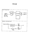
- Figure 5A is a block diagram illustrating the clock and buffer, and error LEDs and buffers, and Figure 5B is a block diagram showing the indicators and switches.
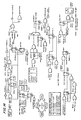
- Figure 6 is a block diagram illustrating the thin-wire interface, the Ethernet transceiver interface and the fiber optic interface.
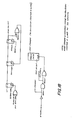
- Figure 7 is a block diagram of the intra repeater interconnect, buffers and receivers.
- Figure 8 is a block diagram of the hub functional partition.
- Figure 9 includes a diagram illustrating a cluster of , hubs coupled together in a daisy chain fashion and a diagram of the inter repeater interconnect cable.
- Figures 10-24 show in detail various aspects of the software and hardware of the invention.
- Referring to Figure 1 of the drawings, the hub is a self-contained unit requiring AC power and having 8 BNC-style connectors for the thin-wire ports. The unit has two other ports, one 15-pin female "D" for connection to an H4000 or IEEE802.3 MAU and a 9-pin female "D" for the connection of up to 8 hubs in a daisy chain fashion. The 9-pin port is the intra repeater interconnect for the hub and provides for intra hub connection.
- The 8 BNC connectors and the transceiver connection will hereinafter be referred to as "ports". The intra repeater interconnect will hereinafter be referred to as "IRI".
- The hub treats all of the thin-wire ports and the two other ports as a common data bus via a gate array that will perform all of the arbitration for the usage of the ports. The joining of the thin-wire ports and the two additional ports creates a larger Ethernet. The hub is not an Ethernet addressable unit on the network. It passes all data that is received on any one port to all 8 other ports and the IRI. The unit has a 32-bit buffer for regeneration of the preamble of the received packets.
- An optional fiber optic interconnect (IRL) is provided so that the hub can be used in harsh environments or for electrical isolation. The module is installed in a 30-pin vertical connector and a cover on the rear panel is removed.
- AC power is provided to the unit via a single standard (3-prong) IEC connector. Tne AC power is not switched to prevent the accidental loss of power to the unit. The unit when powered down exhibits no load on any of the ports. It does however disable the daisy chain if the IRI is in use. (A jumper cable will be provided if the IRI is in use and a unit is being repaired.)
- The hub is used to expand the topology of the thin wires to the much larger Ethernet and to connect up to 64 ports with the IRI to the Ethernet via a single transceiver interconnection. The hub restores the noise and timing margins as signals are transmitted through the unit to the other ports attached to the hub.
- The passing of data from one port to eight other ports is not a simple switching task. The aiming differences of the ports require the buffering of the received data in a first-in/first-out (FIFO) fashion. Collisions on any port on the network need to be passed on to all of the other ports and to the IRI. The data that is received is decoded via a single-chip Manchester encoder/decoder, wherein the data and the clock signals are separated for usage in the gate array. All packets that are received will have the 64-bit preamble restored as it is repeated to the other . ports.
- The normal operation of the hub is as follows:
- (1) A receive is detected on one of the ports.
- (2) A preamble is sent to all of the other 8 ports and the IRI.
- (3) The end of the preamble on the receiving port is detected and the replication of the data on the other ports and the IRI is begun.
- (4) The collision detect input from all ports is continuously monitored and all other ports are enforced as collisions occur.
- There are four major states to the repeater process: Idle, Repeat, Collision and Wait. These four states are the basis of the global state machine and determine the state of the hub. The next state transition terms, such as IR (idle to repeat), are then defined in terms of the inputs to the state machine and determine when the state machine should transition from one state to another. The global state machine determines whether the hub is idle, repeating a packet or jamming a port if there is a collision.
- The transmission to each port is controlled by a one-bit transmit (XMIT) state machine. The global present state and the global next state terms and other inputs determine whether the XMIT bit should be on or off. There is one XMIT state machine for each port of the hub. The one-bit state machines along with the global state machine satisfy all the transition terms of the 802 specification.
- Figures 2 and 3 illustrate the hub state machine and the output state machine, respectively. The following is a set of equations and assigned definitions which control the flow of data to the ports of the hub. The current state of the hub is controlled by the received and collision inputs from all of the ports. Each of the ports are monitored by the state machine and transitions are determined by the condition of the inputs.
-
- ACTIVE, JW output of state flip-flops
- JABBER indicates that 48K bits have been transmitted
- COLXEN carrier recovery time up and 96 bits sent and no collisions
- XMITALL all XMIT bits are on
- RCOLGT1 more than one IRI collision (IRI Jam All)
- RCOMCAR common carrier from IRI
- RANYCOL any collision on the IRI (RCOLEQ1 + RCOLGT1)
- FIFO EMPTY no carrier from receive port and all data sent
- JAM START output of jam start flip flop
- JAM DONE output of jam timer
- GO wait state (heartbeat) timer done
- XMITCOL XMITO*COLO *...XMIT8*COL*8
- SYNC RESET synchronous reset
- careq0 no local carrier
- careql single local carrier
- cargtl multiple local carriers
- coleq0 no local collisions
- coleql single local collision
- colgtl more than one local collision
- RCVCAR carrier drops on the receive port
- SEL802 IEEE 802.3 select
- EOP64 end of preamble and 64 bits sent
- OUTPUTS
- next statel, next state0 input to state flip-flops
- JAM in collision state
- ACTIVE active
- IDLE in idle state
- JAM_START_INPUT input to jam start flip-flop
- IC,IR RC,RW,CW transition outputs for XMITN machines
- IFIELD state = ACTIVE,JW
- OFIELD next_state = next_statel, next_state0 BIND
- idle_state = state/00 this state assignment
- collision state = state/11 produces fewer terms
- wait state = state/01 than several others...
- repeat_state = state/10
- idle_next_state = next state/00 this state assignment
- collision next state = next state/11 produces fewer terms
- wait next state = next state/01 than several others...
- repeat_next_state = next state/10 anycol = (-coleq0 + RANYCOL) jamall = (RCOLGT1 + colgtl)
- The ic transition occurs whenever there is at least one collision anywhere in the system or whenever there are two or more simultaneous carriers from the 9 spurs.
- ic = (-SYNC RESET * (anycol + cargtl))
- (b) idle state to repeat state
- The ir transition occurs whenever there is only one carrier detected from the 9 spurs or when there is an IRI carrier and no local carrier and there are no collisions in the system. ir = (-SYNC RESET * ((careql + RCOMCAR * careq0) * (-anycol)))
- The wi transition occurs if the wait timer (GO) has timed out or in 802 mode and there is a collision in the system.
- wi= (GO + SYNC RESET + SEL802 * (anycol))
- The rc transition occurs whenever there is any collision in the system or if there are no collisions and carrier drops on the receive port and 64 bits of preamble and EOP have not been sent or 96 bits have not been sent and the FIFO buffer is empty.
- rc = (-SYNC RESET * (anycol + -anycol * -RCVCAR & * (-EOP64 + -COLXEN*EOP64*FIFO_EMPTY)))
- The rw transition occurs if there are no collisions in the system and the FIFO is empty or the jabber timer has timed out. rw = (-SYNC RESET * ((COLXEN * -anycol * FIFO EMPTY) + JABBER))
- The cw transition occurs if there are no collisions in the system and the receive port goes inactive and 96 bits have been sent and the carrier recovery timer has timed out. Note that COLXEN asserted implies no collisions. cw = (-SYNC_RESET * (COLXEN * -RCVCAR * ( -JAM START + JAM START *
- JAM DONE) & + JABBER))
- Output jam is combinational, and is asserted in collision state
- JAM = collision state
- Output idle is combinational, and is asserted in idle state IDLE = idle state
- Input to the jam start flip flop
- The bit is set if in the idle state there are multiple collisions detected on the IRI or on the 9 spurs, or if in the repeat state and a collision is detected on a spur that is transmitting or there are multiple collisions detected on the IRI, or in the collision state and the bit was set and the counter is not finished or the jamall condition still exists or there is a collision on a spur that is transmitting.
- JAM_START_INPUT = idle state * -SYNC RESET * (jamall + cargtl) & + repeat state * -SYNC RESET * (RCOLGT1 + XMITCOL) & + collision_state -SYNC_RESET*((JAM_START * -JAM_DONE) + jamall Active is a combinational output
- ACTIVE = repeat state + collision state
- Transfer to idle when:
- in wait state and get GO signal
- get SYNC reset from any state
- in idle state and conditions to transfer out are not true idle next state = wait_state * (wi) &
- + collision state * SYNC RESET &
- + repeat state * SYNC_RESET &
- + (idle_state * -(ic + ir))
- Transfer to collision when:
- in idle state and get any collision
- in repeat state and get any collision
- in collision state and condition to transfer out is false collision next state = idle state * ic &
- + repeat state * rc & + collision state * (-cw)
- Transfer to wait state when:
- in repeat state and there are no collisions and the FIFO buffer is empty
- in collision state and collisions and carrier go away in wait state and have not yet gotten GO wait next state = repeat state * rw &
- + collision state * cw &
- + wait state * -wi
- Transfer to repeat state when:
- in idle state and got a single carrier with no collisions in repeat state and no collisions and FIFO buffer not empty and there is carrier repeat_next_state = idle state * ir &
- + repeat state * - (rc + rw)
- IC = ic--IR* = ir
- RC = rc
- RW = rw
- CW = cw
- INPUTS
- ACTIVE, JW output of state flip-flops
- SYNC COLN collision from port N, synchronized and not segmented
- SYNC CARN carrier from port N, synchronized and not segmented
- XMITCOL XMITO*COLO+...+XMIT8*COL8
- XMITN output of XMIT flip-flop N
- JAM START output of jam start flip-flop
- JAM DONE output of jam counter
- RCOLGT1 IRI jam all
- RCOMCAR carrier on IRI
- RANYCOL any collision on IRI
- careq0 no local carrier
- careql single local carrier
- cargtl multiple local carriers
- dlycoleq0 no local collisions delay by a tick coleq0 no local collisions
- coleql single local collision
- colgtl more than one local collision IR,IC,CW,RW,RC transition terms from global machine
- OUTPUTS
- NXT XMITN input to XMIT flip-flop N
- IFIELD state = ACTIVE,JW state bits of global machine BIND states of global machine idle state = state/00 collision state = state/11 wait stat = state/01 repeat state = state/10
- iricol = (dlycoleq0 * RANYCOL) collision on IRI only anycol = (-coleq0 + RANYCOL) collision anywhere
- jamall = (RCOLGT1 + colgti) multiple collisions on IRI, locally, or both
- This equation is written for output XMITN. All other XMIT outputs have identical form, substituting output number for N.
- Conditions for turning on XMIT bit N: The XMIT bit will be turned on from the idle state if the ir transition is true and there is carrier from one of the 9 spurs and it is not its own spur or there is carrier from only the IRI, or if in the repeat state and the XMIT bit is already on and the global machine will remain in repeat state, i.e. the repeat to wait and the repeat to collision transitions are not true, or if in the repeat state and the repeat to collision transition is true and a single collision occurs on one of the 8 other spurs, or a collision occurs only on the IRI (multiple or single) or a collision occurs on a spur that is transmitting, or in the idle state and the idle to collision transition is true and there is one collision and it is not our own port or there is a collision on the IRI or there is more than one collision on the 9 spurs or there is more than one carrier on the 9 spurs, or in the collision state and remaining there (i.e. the collision to wait transition is not true) and either: there is a collision on the IRI or the jamall condition is true or there is one collision on another input line or the XMIT bit is on and there is a collision anywhere or the jam counter is started and not done.
- NXT XMITN = idle_ state*IR*(careq1 * -SYNC_CARN + careqO*RCOMCAR) &
- + repeat state * XMITN * -(RW+RC) &
- + repeat state * RC *(-(coleql*SYNC COLN + coleq0 * -XMITN) + iricol & + RCOLGT1 + XMITCOL) &
- + idle_state * IC *(-(coleql*SYNC COLN) + iricol + colgtl + cargtl) &
- + collision state *-CW*(iricol + jamall &
- + -SYNC_COLN*coleq1 + XMITN*-anycol + JAM START * -JAM DONE)
- All timing for the hub is generated from a 20.00-MHz, .01% oscillator. This clock is used for timing of the gate array and the transmit data. Reference is made to Figures 4-8 which illustrate in a block diagram the construction of the hub.
- The major data path of the hub is via the transceiver chip from the BNC connector to the serial interface adapter (SIA) and from there to the gate array. The SIA performs all of the decoding of the Manchester data and the separation of the data and clock signals. At this point the data is multiplexed to the proper data path. The data is then buffered in the FIFO fashion. A 32-bit buffer, operating on a first-in/first-out basis, is employed for buffering the data that is received from any one of the ports. The FIFO buffer is used to allow for speed differences within the network. It holds the data until the entire 64-bit preamble is regenerated and sent to the eight transmitting ports.
- The decoding of the data is performed in the SIA chip. The encoding of the data to Manchester format upon transmission is also performed by the SIA chip.
- The total amount of jitter on the receive pair that the hub will properly Manchester decode with no errors is 20 ns or less. Jitter is defined as the edge-to-edge difference in the received encoded data.
- The hub replicates the data of a received signal if the preamble is less than 256 bits and more than 40 bits long. If these error conditions occur, the FIFO may be underrun on a longer preamble and overrun on a short preamble. The hub will always transmit at least 63 bits of preamble.
- The hub buffers all data from any port that is a valid packet in the FIFO buffer as the data bits are received. The FIFO is checked for the end of preamble (EOP) signal. This signifies the start of valid data bits in the received packet.
- . Upon the detection of an EOP signal at the FIFO;buffer output before the regenerated preamble is completed, the FIFO delays the unloading of the received bits from the FIFO until the regenerated preamble is completed. Upon the detection of 63 bits of regenerated preamble being sent and not having detected the EOP signal, the hub begins the output of data from the FIFO buffer. This action will cause the addition of extra bits of preamble due to the additional bits of preamble in the FIFO buffer.
- The hub can detect the "11" or "00" pattern as the EOP signal. If no EOP signal is detected, as in the above case, the hub will pass the data bits with the regenerated preamble as close to that of the reception.
- The use of autosegmentation increases the availability of the network. The segmentation of a circuit is performed when a fault is detected on a port of the hub. The faulty line continues to receive and transmissions are attempted to verify that the port is still faulty. This mode of operation on this port of the hub is known as "segmentation" or the removal of this port from active usage.
- The hub will reconnect a "segmented" port of the unit when a reception is completed with no errors. An error-free reception is one with no collision detect occurrence and at least 512 bits of data.
- The hub segments a port upon the following conditions:
- (1) Excessive Collisions: A counter is incremented on each port for each successive collision of the hub and if this count reaches 64, the port is segmented. The counter is reset on each non-collided transmission.
- (2) No Loopback: The hub does not receive a loopback of the transmitted data within a specified loop time.
- (3) Loss of Carrier: This is the failure to receive carrier for a transmission which has been started, and is caused by a cable fault or by collisions on the cable.
- *Another problem which may occur is defined as "runt pockets". Upon transmission to a port the hub will transmit at least 96 bits of data for any reception. This is to ensure that fragments are long enough for all parties to detect the presence of the collision. This is to make certain that a collision with a runt packet (not legal length) is sent through the hub. The hub will add bits to receptions that are not 96 bits long. This is done until 96 bits are transmitted.
- The hub is designed so that the unit has a completely functional self-test. There are two modes of placing the unit into the self-test: (1) power-up of the unit and (2) press the reset button. The unit has two distinct types of self-test for isolating various faults on the unit. These are an internal self-test and an external self-test.
- During the initial power-up of the unit the internal self-test is run. This is run for one complete cycle of the 9 ports of the gate array and a packet containing 256 bits of preamble and 1792 bits of data (1's) is passed to each port. The data is looped internal to the gate array in the internal FIFO buffer and compared. The collision counters and the segmentation of each port is checked before completion of the internal self-test. Upon the detection of an error on a port, this is indicated by error LEDs that are dedicated to each of the 9 ports.
- The external self-test is activated by the pressing of the reset button on the rear of the unit. This test will be run after the internal test has been completed. The external test loops a packet of 256 bits of preamble and 1792 bits of data (1's) and compares the looped packet. Each of the 8 BNC ports is tested and also the Ethernet port. The test also checks for the loss of carrier and the loopback capability of the transceiver chips.
- The hub is capable of running the internal self-test in a continuous mode when the Loop On Test jumper is installed. This mode is run until the reset button is sensed and the hub runs one more pass of self-test and enters a mode of continuous external self-test. These are diagnostic features for burning the units and for service personnel. The jumper for this is accessible to the user without opening the enclosure.
- A collision presence test is performed after the transmission of a good packet to all of the ports externally. Upon the detection of the completion of the transmission, the collision presence will generate a burst of 6 transitions at the normal 10-MHz rate. The hub checks to make certain that this short burst of data does occur after an external transmission on each port. After the external part of the self-test is completed, the generation of the collision presence test is disabled on all of the thin-wire ports. This is a function that is only performed during the self-test. The transceiver heartbeat is disabled after completion of the self-test.
- It is possible to operate two hub units on the same Ethernet coaxial cable via two H4000s when the IRI port is in use in multiple hub applications. The number of hubs that can be attached to the coaxial cable is a maximum of two. The second connection will be the backup path to the Ethernet coaxial cable. The second unit must have the "standby" switch in the standby position. The primary hub must be in the "active" switch position. All of the remaining hub units of the daisy chain can be set to any mode (standby/active). These units will segment the Ethernet transceiver port due to a lack of loopback path.
- The primary hub will be replaced by the standby unit if the standby records a predetermined number of valid packets that are not repeated to the Ethernet port. Only one of the hubs on any given Ethernet cluster can be the primary unit.
- The hub can be configured to operate in compliance with 802.3 jumperover time of 1.0 usec and 96-bit preamble. The unit can do this automatically on the first transmit after self-test. A test is performed to see if the heartbeat is within the 3.2-usec window. This will then assume 802.3 operation if the heartbeat is not present. The jumper for 802.3 is removed to prevent the test from occurring.
- Figure 9 illustrates how a cluster of hubs are coupled together. Each hub has an IRI port which serves as the interconnect point between the hubs. An IRI cable is employed for coupling the hubs together in a daisy chain fashion.
- The IRI cable has two ends, wherein one end has a male connector for coupling into the IRI port on the hub and the other end has both a male and a female connector, the male connector being for coupling to an IRI port on another hub and the female connector being for coupling to another IRI cable. The following is a description of the signals on each of the pins illustrated in Figure 9.
- The IRI is to be used when the need for more than one hub is required and the user does not wish to install an additional transceiver. The additional hubs are connected via the 9-pin D-type connector. The termination of the cable can be made by placing a termination connector at the far end of the connected units. All of the hubs monitor a common bus for the following signals: carrier, receive clock, receive data and collision. These are the "OR" of the 8 channels of the respective signals. In addition, an activity signal is passed from each unit for the indication of the completion of jams.
- It is also to be understood that the following claims are intended to cover all of the generic and specific features of the invention herein described.
Claims (5)
wherein a packet of information, containing a preamble and data, being transmitted on a cable coupled to any of the ports is coupled to all of the other ports, said data packet containing noise and timing margins, said repeater further comprising restoring means capable of restoring said noise and timing margins.
wherein said standard transceiver cable transmits information packets, said transceiver cable is coupled to said first repeater transceiver cable port and said second repeater transceiver port, said first repeater is capable of outputting all information packets inputted into either the standard repeater port or any of the plurality of thin-wire ports to all of the ports except the port to which the information packet was inputted, said second repeater is capable of monitoring said outputted information over said intra repeater interconnect port and said information transmitted on said standard transceiver cable, and said second repeater is employed for automatic failure recovery in said standby mode, said failure recovery occurring when said second repeater monitors information packet transmission at said standard transceiver port which is not repeated at said intra repeater interconnect port.
said male connector of said second end coupling into the interconnect port of another repeater and said female connector of said second end being available for coupling with another interconnect cable such that a plurality of multiport repeaters can be coupled together in a daisy chain fashion.
Priority Applications (1)
| Application Number | Priority Date | Filing Date | Title |
|---|---|---|---|
| AT86402498T ATE100260T1 (en) | 1985-11-08 | 1986-11-07 | THIN WIRE MULTI-JOT INTERMEDIATE REGEN. |
Applications Claiming Priority (2)
| Application Number | Priority Date | Filing Date | Title |
|---|---|---|---|
| US796470 | 1985-11-08 | ||
| US06/796,470 US4825435A (en) | 1985-11-08 | 1985-11-08 | Multiport repeater |
Publications (3)
| Publication Number | Publication Date |
|---|---|
| EP0222669A2 true EP0222669A2 (en) | 1987-05-20 |
| EP0222669A3 EP0222669A3 (en) | 1989-02-22 |
| EP0222669B1 EP0222669B1 (en) | 1994-01-12 |
Family
ID=25168264
Family Applications (1)
| Application Number | Title | Priority Date | Filing Date |
|---|---|---|---|
| EP86402498A Expired - Lifetime EP0222669B1 (en) | 1985-11-08 | 1986-11-07 | Thin-wire multiport repeater |
Country Status (12)
| Country | Link |
|---|---|
| US (1) | US4825435A (en) |
| EP (1) | EP0222669B1 (en) |
| JP (1) | JPH0671261B2 (en) |
| KR (1) | KR950002267B1 (en) |
| CN (1) | CN1009894B (en) |
| AT (1) | ATE100260T1 (en) |
| AU (1) | AU591193B2 (en) |
| CA (1) | CA1279115C (en) |
| DE (1) | DE3689535T2 (en) |
| FI (1) | FI91583C (en) |
| IL (1) | IL80553A (en) |
| MX (1) | MX167433B (en) |
Cited By (10)
| Publication number | Priority date | Publication date | Assignee | Title |
|---|---|---|---|---|
| EP0467583A1 (en) * | 1990-07-20 | 1992-01-22 | Advanced Micro Devices, Inc. | Repeater |
| EP0480598A1 (en) * | 1990-10-10 | 1992-04-15 | Advanced Micro Devices, Inc. | Repeater method and apparatus |
| EP0493892A2 (en) * | 1990-12-31 | 1992-07-08 | AT&T Corp. | Intrusion detection apparatus for local area network |
| EP0495575A1 (en) * | 1991-01-18 | 1992-07-22 | National Semiconductor Corporation | Repeater interface controller |
| WO1992017963A2 (en) * | 1991-04-04 | 1992-10-15 | 3Com Technologies Limited | Repeaters for digital data networks |
| WO1993014586A1 (en) * | 1992-01-20 | 1993-07-22 | Madge Networks Limited | Communication system |
| EP0568520A2 (en) * | 1992-04-30 | 1993-11-03 | Fisher-Rosemount Systems, Inc. | Regenerative communication channel extender |
| WO1996028916A1 (en) * | 1995-03-13 | 1996-09-19 | Compaq Computer Corporation | Method and apparatus for networking data devices using an uplink module |
| WO1997029572A1 (en) * | 1996-02-05 | 1997-08-14 | Xinex Networks Inc. | Network for multimedia asynchronous transfer mode digital signal transmission and components thereof |
| US5799041A (en) * | 1996-02-05 | 1998-08-25 | Xinex Networks Inc. | Network for multimedia asynchronous transfer mode digital signal transmission and components thereof |
Families Citing this family (67)
| Publication number | Priority date | Publication date | Assignee | Title |
|---|---|---|---|---|
| US5844596A (en) | 1989-07-14 | 1998-12-01 | Inline Connection Corporation | Two-way RF communication at points of convergence of wire pairs from separate internal telephone networks |
| US6243446B1 (en) | 1997-03-11 | 2001-06-05 | Inline Connections Corporation | Distributed splitter for data transmission over twisted wire pairs |
| US5010399A (en) * | 1989-07-14 | 1991-04-23 | Inline Connection Corporation | Video transmission and control system utilizing internal telephone lines |
| US5265124A (en) * | 1990-02-15 | 1993-11-23 | Advanced Micro Devices, Inc. | Integrated multi-port repeater having shared resources |
| US5179554A (en) * | 1991-04-08 | 1993-01-12 | Digital Equipment Corporation | Automatic association of local area network station addresses with a repeater port |
| JP2752265B2 (en) * | 1991-05-10 | 1998-05-18 | 株式会社東芝 | Computer system with disconnection function from LAN |
| US5339307A (en) * | 1991-06-28 | 1994-08-16 | Digital Equipment Corporation | Data communication system with a local network interface |
| US5296936A (en) * | 1991-07-22 | 1994-03-22 | International Business Machines Corporation | Communication apparatus and method for transferring image data from a source to one or more receivers |
| US5471472A (en) * | 1991-07-30 | 1995-11-28 | Synernetics Inc. | Network multiplexer |
| US5432907A (en) * | 1992-05-12 | 1995-07-11 | Network Resources Corporation | Network hub with integrated bridge |
| US5742760A (en) * | 1992-05-12 | 1998-04-21 | Compaq Computer Corporation | Network packet switch using shared memory for repeating and bridging packets at media rate |
| USRE39395E1 (en) | 1992-11-02 | 2006-11-14 | Negotiated Data Solutions Llc | Data communication network with transfer port, cascade port and/or frame synchronizing signal |
| EP0596651A1 (en) | 1992-11-02 | 1994-05-11 | National Semiconductor Corporation | Network for data communication with isochronous capability |
| USRE39116E1 (en) * | 1992-11-02 | 2006-06-06 | Negotiated Data Solutions Llc | Network link detection and generation |
| EP0596648A1 (en) * | 1992-11-02 | 1994-05-11 | National Semiconductor Corporation | Network link endpoint capability detection |
| US5355375A (en) * | 1993-03-18 | 1994-10-11 | Network Systems Corporation | Hub controller for providing deterministic access to CSMA local area network |
| US5400360A (en) * | 1993-03-23 | 1995-03-21 | Limitorque Corporation | Repeater for a digital control system |
| US5469438A (en) * | 1994-01-28 | 1995-11-21 | At&T Ipm Corp. | Method of transmitting signals in an extendible local area network |
| US5467351A (en) * | 1994-04-22 | 1995-11-14 | At&T Corp. | Extendible round robin local area hub network |
| FR2726954B1 (en) * | 1994-11-15 | 1997-01-24 | Dassault Electronique | RELAY UNIT BETWEEN STATION AND COMMUNICATION CHANNEL, PARTICULARLY FOR ETHERNET NETWORKS |
| US5621893A (en) * | 1994-11-22 | 1997-04-15 | Lucent Technologies Inc. | System for expanding ports wherein segment switch selectively associates plurality of hubs coupled to first arbiter and plurality of hubs coupled to second arbiter |
| US5666488A (en) * | 1994-11-22 | 1997-09-09 | Lucent Technologies Inc. | Port expansion network and method for lAN hubs |
| JPH08223195A (en) * | 1994-11-22 | 1996-08-30 | At & T Corp | Local area hub network allowing expansion of port number andmethod of expanding its port number |
| US5533018A (en) | 1994-12-21 | 1996-07-02 | National Semiconductor Corporation | Multi-protocol packet framing over an isochronous network |
| US5896508A (en) * | 1995-02-23 | 1999-04-20 | Advanced Micro Devices, Inc. | Hub-network adapter device for a file server personal computer |
| US5629685A (en) * | 1995-02-23 | 1997-05-13 | International Business Machines Corporation | Segmentable addressable modular communication network hubs |
| US5680113A (en) * | 1995-02-24 | 1997-10-21 | International Business Machines Corporation | Dynamic address assignments to serially connected devices |
| US5608729A (en) * | 1995-04-20 | 1997-03-04 | Lucent Technologies Inc. | Method and apparatus for providing two-way data communication cover a widely distributed network |
| US5742602A (en) * | 1995-07-12 | 1998-04-21 | Compaq Computer Corporation | Adaptive repeater system |
| US5754540A (en) * | 1995-07-18 | 1998-05-19 | Macronix International Co., Ltd. | Expandable integrated circuit multiport repeater controller with multiple media independent interfaces and mixed media connections |
| US5805597A (en) * | 1996-06-04 | 1998-09-08 | National Semiconductor Corporation | Method and apparatus for providing low power basic telephony type service over a twisted pair ethernet physical layer |
| AU720165B2 (en) * | 1996-07-12 | 2000-05-25 | Cais, Inc. | Digital communication system for apartment buildings and similar structures using existing telephone wires |
| US6041061A (en) * | 1997-01-31 | 2000-03-21 | Macronix International Co., Ltd. | Internal arbiter for a repeater in a computer network |
| KR100284485B1 (en) * | 1998-06-15 | 2001-03-15 | 신승영 | LAN card |
| US6480510B1 (en) | 1998-07-28 | 2002-11-12 | Serconet Ltd. | Local area network of serial intelligent cells |
| US6690677B1 (en) | 1999-07-20 | 2004-02-10 | Serconet Ltd. | Network for telephony and data communication |
| US20040230710A1 (en) * | 1999-07-27 | 2004-11-18 | Inline Connection Corporation | System and method of automatic installation of computer peripherals |
| US6704824B1 (en) * | 1999-07-27 | 2004-03-09 | Inline Connection Corporation | Universal serial bus adapter with automatic installation |
| US6243510B1 (en) | 2000-03-13 | 2001-06-05 | Apcon, Inc. | Electronically-controllable fiber optic patch panel |
| US6549616B1 (en) | 2000-03-20 | 2003-04-15 | Serconet Ltd. | Telephone outlet for implementing a local area network over telephone lines and a local area network using such outlets |
| IL135744A (en) | 2000-04-18 | 2008-08-07 | Mosaid Technologies Inc | Telephone communication system over a single telephone line |
| US6842459B1 (en) | 2000-04-19 | 2005-01-11 | Serconet Ltd. | Network combining wired and non-wired segments |
| JP4632574B2 (en) * | 2001-05-25 | 2011-02-16 | 株式会社日立製作所 | Storage device, file data backup method, and file data copy method |
| IL144158A (en) | 2001-07-05 | 2011-06-30 | Mosaid Technologies Inc | Outlet for connecting an analog telephone set to a digital data network carrying voice signals in digital form |
| EP2523358A3 (en) | 2001-10-11 | 2012-11-21 | Mosaid Technologies Incorporated | Outlet with analog signal adapter |
| IL154234A (en) | 2003-01-30 | 2010-12-30 | Mosaid Technologies Inc | Method and system for providing dc power on local telephone lines |
| IL154921A (en) | 2003-03-13 | 2011-02-28 | Mosaid Technologies Inc | Telephone system having multiple distinct sources and accessories therefor |
| IL157787A (en) | 2003-09-07 | 2010-12-30 | Mosaid Technologies Inc | Modular outlet for data communications network |
| IL159838A0 (en) | 2004-01-13 | 2004-06-20 | Yehuda Binder | Information device |
| IL161869A (en) | 2004-05-06 | 2014-05-28 | Serconet Ltd | System and method for carrying a wireless based signal over wiring |
| US7873058B2 (en) | 2004-11-08 | 2011-01-18 | Mosaid Technologies Incorporated | Outlet with analog signal adapter, a method for use thereof and a network using said outlet |
| US7813451B2 (en) | 2006-01-11 | 2010-10-12 | Mobileaccess Networks Ltd. | Apparatus and method for frequency shifting of a wireless signal and systems using frequency shifting |
| EP2203799A4 (en) | 2007-10-22 | 2017-05-17 | Mobileaccess Networks Ltd. | Communication system using low bandwidth wires |
| US8175649B2 (en) | 2008-06-20 | 2012-05-08 | Corning Mobileaccess Ltd | Method and system for real time control of an active antenna over a distributed antenna system |
| EP2399141A4 (en) | 2009-02-08 | 2012-08-01 | Corning Mobileaccess Ltd | Communication system using cables carrying ethernet signals |
| US8750903B1 (en) | 2012-02-28 | 2014-06-10 | CellAntenna Corporation | Cell phone control and localization for restricted facilities |
| EP2829152A2 (en) | 2012-03-23 | 2015-01-28 | Corning Optical Communications Wireless Ltd. | Radio-frequency integrated circuit (rfic) chip(s) for providing distributed antenna system functionalities, and related components, systems, and methods |
| US9797978B1 (en) | 2014-09-03 | 2017-10-24 | Howard Melamed | UAV, system, and method for radio frequency spectral analysis |
| US9184960B1 (en) | 2014-09-25 | 2015-11-10 | Corning Optical Communications Wireless Ltd | Frequency shifting a communications signal(s) in a multi-frequency distributed antenna system (DAS) to avoid or reduce frequency interference |
| US9689976B2 (en) | 2014-12-19 | 2017-06-27 | Xidrone Systems, Inc. | Deterent for unmanned aerial systems |
| US9715009B1 (en) | 2014-12-19 | 2017-07-25 | Xidrone Systems, Inc. | Deterent for unmanned aerial systems |
| US9529360B1 (en) | 2015-01-28 | 2016-12-27 | Howard Melamed | System and method for detecting and defeating a drone |
| US9847035B1 (en) | 2015-01-28 | 2017-12-19 | Howard Melamed | Methods for radio frequency spectral analysis |
| WO2017136166A1 (en) * | 2016-02-04 | 2017-08-10 | TEN DIGIT Communications LLC | Intermediary device for data message network routing and enhancement in a contact center environment |
| US10367766B2 (en) | 2017-01-20 | 2019-07-30 | TEN DIGIT Communications LLC | Intermediary device for data message network routing |
| US10907940B1 (en) | 2017-12-12 | 2021-02-02 | Xidrone Systems, Inc. | Deterrent for unmanned aerial systems using data mining and/or machine learning for improved target detection and classification |
| US11277251B1 (en) | 2019-07-03 | 2022-03-15 | Michael Patrick Millard | Radio frequency spectrum management system and method |
Citations (3)
| Publication number | Priority date | Publication date | Assignee | Title |
|---|---|---|---|---|
| US4034470A (en) * | 1974-10-11 | 1977-07-12 | Amp Incorporated | Method for fabricating multi-conductor tap connector |
| WO1983003178A1 (en) * | 1982-03-05 | 1983-09-15 | Western Electric Co | Improved multipoint data communication system with local arbitration |
| EP0120323A1 (en) * | 1983-02-28 | 1984-10-03 | Siemens Aktiengesellschaft | Arrangement for local data transmission between a data processing unit and several data terminals over standard transmission interfaces |
Family Cites Families (13)
| Publication number | Priority date | Publication date | Assignee | Title |
|---|---|---|---|---|
| US3889064A (en) * | 1974-03-27 | 1975-06-10 | Nasa | Asynchronous, multiplexing, single line transmission and recovery data system |
| US4334306A (en) * | 1978-06-02 | 1982-06-08 | Texas Instruments Incorporated | Transparent intelligent network for data and voice |
| US4228535A (en) * | 1979-02-26 | 1980-10-14 | Rockwell International Corporation | Dual TDM switching apparatus |
| US4347498A (en) * | 1979-11-21 | 1982-08-31 | International Business Machines Corporation | Method and means for demand accessing and broadcast transmission among ports in a distributed star network |
| FR2478910A1 (en) * | 1980-03-18 | 1981-09-25 | Trt Telecom Radio Electr | REPLACER TELELOCATION SYSTEM |
| US4399531A (en) * | 1980-09-29 | 1983-08-16 | Rockwell International Corporation | Distributed digital data communications network |
| US4417334A (en) * | 1981-04-16 | 1983-11-22 | Ncr Corporation | Data processing system having dual-channel system bus |
| JPS59165537A (en) * | 1983-03-10 | 1984-09-18 | Nec Corp | Light star repeater |
| JPS59169229A (en) * | 1983-03-16 | 1984-09-25 | Fujitsu Ltd | Duplex switch control system |
| US4491968A (en) * | 1983-04-07 | 1985-01-01 | Comsonics, Inc. | Status monitor |
| US4556974A (en) * | 1983-10-07 | 1985-12-03 | Honeywell Inc. | Method for passing a token in a local-area network |
| US4598399A (en) * | 1984-11-20 | 1986-07-01 | Rockwell International Corporation | Multichannel multisite signal protection channel switching apparatus |
| US4706081A (en) * | 1984-12-14 | 1987-11-10 | Vitalink Communications Corporation | Method and apparatus for bridging local area networks |
-
1985
- 1985-11-08 US US06/796,470 patent/US4825435A/en not_active Expired - Lifetime
-
1986
- 1986-11-06 MX MX004275A patent/MX167433B/en unknown
- 1986-11-07 CA CA000522513A patent/CA1279115C/en not_active Expired - Fee Related
- 1986-11-07 IL IL80553A patent/IL80553A/en unknown
- 1986-11-07 EP EP86402498A patent/EP0222669B1/en not_active Expired - Lifetime
- 1986-11-07 AT AT86402498T patent/ATE100260T1/en not_active IP Right Cessation
- 1986-11-07 FI FI864536A patent/FI91583C/en not_active IP Right Cessation
- 1986-11-07 DE DE3689535T patent/DE3689535T2/en not_active Expired - Fee Related
- 1986-11-07 AU AU64948/86A patent/AU591193B2/en not_active Ceased
- 1986-11-07 JP JP61264127A patent/JPH0671261B2/en not_active Expired - Lifetime
- 1986-11-08 KR KR1019860009470A patent/KR950002267B1/en not_active IP Right Cessation
- 1986-11-08 CN CN86107753A patent/CN1009894B/en not_active Expired
Patent Citations (3)
| Publication number | Priority date | Publication date | Assignee | Title |
|---|---|---|---|---|
| US4034470A (en) * | 1974-10-11 | 1977-07-12 | Amp Incorporated | Method for fabricating multi-conductor tap connector |
| WO1983003178A1 (en) * | 1982-03-05 | 1983-09-15 | Western Electric Co | Improved multipoint data communication system with local arbitration |
| EP0120323A1 (en) * | 1983-02-28 | 1984-10-03 | Siemens Aktiengesellschaft | Arrangement for local data transmission between a data processing unit and several data terminals over standard transmission interfaces |
Non-Patent Citations (2)
| Title |
|---|
| DATA COMMUNICATIONS, vol. 14, no. 10, September 1985, pages 267,268,271,272,275,276; J. LEONG: "Nuts-and bolts guide to Ehternet installation and interconnection" * |
| IEEE TRANSACTIONS ON POWER APPARATUS AND SYSTEMS, vol. PAS-102, no. 1, January 1983, pages 127-133, IEEE, New York, US; D. DAMSKER: "Totally distributed, redundantly structured hardware and software local computer control network" * |
Cited By (25)
| Publication number | Priority date | Publication date | Assignee | Title |
|---|---|---|---|---|
| US5265123A (en) * | 1990-02-15 | 1993-11-23 | Advanced Micro Devices, Inc. | Expandable repeater |
| US5430762A (en) * | 1990-02-15 | 1995-07-04 | Advanced Micro Devices, Inc. | Expandable repeater |
| US5315590A (en) * | 1990-02-15 | 1994-05-24 | Advanced Micro Devices Inc. | Selectable repeater port reconnection method and apparatus |
| EP0467583A1 (en) * | 1990-07-20 | 1992-01-22 | Advanced Micro Devices, Inc. | Repeater |
| EP0480598A1 (en) * | 1990-10-10 | 1992-04-15 | Advanced Micro Devices, Inc. | Repeater method and apparatus |
| EP0493892A2 (en) * | 1990-12-31 | 1992-07-08 | AT&T Corp. | Intrusion detection apparatus for local area network |
| EP0493892A3 (en) * | 1990-12-31 | 1994-09-21 | American Telephone & Telegraph | Intrusion detection apparatus for local area network |
| EP0495575A1 (en) * | 1991-01-18 | 1992-07-22 | National Semiconductor Corporation | Repeater interface controller |
| KR100245903B1 (en) * | 1991-01-18 | 2000-03-02 | 클라크 3세 존 엠. | Repeater interface controller |
| US5299195A (en) * | 1991-01-18 | 1994-03-29 | National Semiconductor Corporation | Repeater interface controller with multiple port node interfaces |
| US5384767A (en) * | 1991-01-18 | 1995-01-24 | National Semiconductor Corporation | Segment tester for a repeater interface controller |
| US5396495A (en) * | 1991-01-18 | 1995-03-07 | National Semiconductor Corporation | Hub management bus architecture for repeater interface controller |
| US5430726A (en) * | 1991-01-18 | 1995-07-04 | Moorwood; Charles A. | Repeater interface controller with a shared data bus |
| WO1992017963A3 (en) * | 1991-04-04 | 1992-11-12 | 3Com Technologies Ltd | Repeaters for digital data networks |
| WO1992017963A2 (en) * | 1991-04-04 | 1992-10-15 | 3Com Technologies Limited | Repeaters for digital data networks |
| WO1993014586A1 (en) * | 1992-01-20 | 1993-07-22 | Madge Networks Limited | Communication system |
| EP0568520A3 (en) * | 1992-04-30 | 1998-05-20 | Fisher-Rosemount Systems, Inc. | Regenerative communication channel extender |
| EP0568520A2 (en) * | 1992-04-30 | 1993-11-03 | Fisher-Rosemount Systems, Inc. | Regenerative communication channel extender |
| WO1996028916A1 (en) * | 1995-03-13 | 1996-09-19 | Compaq Computer Corporation | Method and apparatus for networking data devices using an uplink module |
| US5796738A (en) * | 1995-03-13 | 1998-08-18 | Compaq Computer Corporation | Multiport repeater with collision detection and jam signal generation |
| US5854790A (en) * | 1995-03-13 | 1998-12-29 | Compaq Computer Corp. | Method and apparatus for networking data devices using an uplink module |
| WO1997029572A1 (en) * | 1996-02-05 | 1997-08-14 | Xinex Networks Inc. | Network for multimedia asynchronous transfer mode digital signal transmission and components thereof |
| US5799041A (en) * | 1996-02-05 | 1998-08-25 | Xinex Networks Inc. | Network for multimedia asynchronous transfer mode digital signal transmission and components thereof |
| US5878221A (en) * | 1996-02-05 | 1999-03-02 | Xinex Networks Inc. | Network for multimedia asynchronous transfer mode digital signal transmission and components thereof |
| AU712963B2 (en) * | 1996-02-05 | 1999-11-18 | Tri-Link Technologies Inc. | Network for multimedia asynchronous transfer mode digital signal transmission and components thereof |
Also Published As
| Publication number | Publication date |
|---|---|
| EP0222669A3 (en) | 1989-02-22 |
| CN1009894B (en) | 1990-10-03 |
| AU591193B2 (en) | 1989-11-30 |
| IL80553A (en) | 1991-03-10 |
| CA1279115C (en) | 1991-01-15 |
| AU6494886A (en) | 1987-05-14 |
| FI864536A0 (en) | 1986-11-07 |
| KR870005522A (en) | 1987-06-09 |
| US4825435A (en) | 1989-04-25 |
| MX167433B (en) | 1993-03-22 |
| KR950002267B1 (en) | 1995-03-15 |
| EP0222669B1 (en) | 1994-01-12 |
| JPH0671261B2 (en) | 1994-09-07 |
| JPS62271539A (en) | 1987-11-25 |
| FI91583B (en) | 1994-03-31 |
| CN86107753A (en) | 1987-09-23 |
| DE3689535T2 (en) | 1994-07-28 |
| ATE100260T1 (en) | 1994-01-15 |
| IL80553A0 (en) | 1987-02-27 |
| DE3689535D1 (en) | 1994-02-24 |
| FI864536A (en) | 1987-05-09 |
| FI91583C (en) | 1994-07-11 |
Similar Documents
| Publication | Publication Date | Title |
|---|---|---|
| EP0222669B1 (en) | Thin-wire multiport repeater | |
| JP2909084B2 (en) | Run communication device and media adapter used for it | |
| US5249183A (en) | Interfacing unit for local area networks | |
| US5577023A (en) | Method and apparatus for automatic configuration of a network connection | |
| EP0939511B1 (en) | Method and arrangement in a network repeater for automatically changing link speed | |
| US5345447A (en) | Switching hub which implements a virtual bus for interconnecting stations on a CSMA network | |
| EP0372801A2 (en) | A method and apparatus for configuring data paths within a network station | |
| US5387902A (en) | Data networks | |
| Rufino et al. | A Columbus' egg idea for CAN media redundancy | |
| Ross | Rings are'round for good! | |
| US5289458A (en) | Apparatus for accomplishing autoport selection | |
| EP0195595A2 (en) | Local area network | |
| Hopper et al. | Design and use of an integrated Cambridge ring | |
| US4528675A (en) | FSK modem for bidirectional loop communications system | |
| GB2218599A (en) | Local access network signel regenerator | |
| Rufino | Dual-media redundancy mechanisms for CAN | |
| JPH04299630A (en) | Method for reconnecting repeater and port which is divided at repeater | |
| EP0230116B1 (en) | Tdm ring communication medium | |
| Cripps et al. | SONET: a simple open network | |
| Linde | Active Star Architectures For Fiber Optics Ethernet | |
| Henderson et al. | Options for campus fiber networks | |
| Saltzer | DIFFERENCES BETWEEN THE IBM RESEARCH Z-RING AND THE LCS VERSION TWO RING | |
| CA2124771A1 (en) | Switching module for redundant local area network | |
| Nassar | Token ring troubleshooting guide | |
| JPS61296833A (en) | Time division bus communication system |
Legal Events
| Date | Code | Title | Description |
|---|---|---|---|
| PUAI | Public reference made under article 153(3) epc to a published international application that has entered the european phase |
Free format text: ORIGINAL CODE: 0009012 |
|
| AK | Designated contracting states |
Kind code of ref document: A2 Designated state(s): AT BE CH DE ES FR GB GR IT LI LU NL SE |
|
| PUAL | Search report despatched |
Free format text: ORIGINAL CODE: 0009013 |
|
| AK | Designated contracting states |
Kind code of ref document: A3 Designated state(s): AT BE CH DE ES FR GB GR IT LI LU NL SE |
|
| 17P | Request for examination filed |
Effective date: 19890731 |
|
| 17Q | First examination report despatched |
Effective date: 19891108 |
|
| GRAA | (expected) grant |
Free format text: ORIGINAL CODE: 0009210 |
|
| AK | Designated contracting states |
Kind code of ref document: B1 Designated state(s): AT BE CH DE ES FR GB GR IT LI LU NL SE |
|
| PG25 | Lapsed in a contracting state [announced via postgrant information from national office to epo] |
Ref country code: SE Effective date: 19940112 Ref country code: NL Effective date: 19940112 Ref country code: LI Effective date: 19940112 Ref country code: GR Free format text: LAPSE BECAUSE OF FAILURE TO SUBMIT A TRANSLATION OF THE DESCRIPTION OR TO PAY THE FEE WITHIN THE PRESCRIBED TIME-LIMIT Effective date: 19940112 Ref country code: CH Effective date: 19940112 Ref country code: BE Effective date: 19940112 Ref country code: AT Effective date: 19940112 |
|
| REF | Corresponds to: |
Ref document number: 100260 Country of ref document: AT Date of ref document: 19940115 Kind code of ref document: T |
|
| REF | Corresponds to: |
Ref document number: 3689535 Country of ref document: DE Date of ref document: 19940224 |
|
| ITF | It: translation for a ep patent filed |
Owner name: STUDIO TORTA SOCIETA' SEMPLICE |
|
| PG25 | Lapsed in a contracting state [announced via postgrant information from national office to epo] |
Ref country code: ES Free format text: LAPSE BECAUSE OF FAILURE TO SUBMIT A TRANSLATION OF THE DESCRIPTION OR TO PAY THE FEE WITHIN THE PRESCRIBED TIME-LIMIT Effective date: 19940423 |
|
| REG | Reference to a national code |
Ref country code: CH Ref legal event code: PL |
|
| ET | Fr: translation filed | ||
| NLV1 | Nl: lapsed or annulled due to failure to fulfill the requirements of art. 29p and 29m of the patents act | ||
| PLBE | No opposition filed within time limit |
Free format text: ORIGINAL CODE: 0009261 |
|
| STAA | Information on the status of an ep patent application or granted ep patent |
Free format text: STATUS: NO OPPOSITION FILED WITHIN TIME LIMIT |
|
| 26N | No opposition filed | ||
| PGFP | Annual fee paid to national office [announced via postgrant information from national office to epo] |
Ref country code: ES Payment date: 19961108 Year of fee payment: 11 |
|
| PGFP | Annual fee paid to national office [announced via postgrant information from national office to epo] |
Ref country code: LU Payment date: 19981201 Year of fee payment: 13 |
|
| PG25 | Lapsed in a contracting state [announced via postgrant information from national office to epo] |
Ref country code: LU Free format text: LAPSE BECAUSE OF NON-PAYMENT OF DUE FEES Effective date: 19991107 |
|
| REG | Reference to a national code |
Ref country code: GB Ref legal event code: 732E |
|
| PGFP | Annual fee paid to national office [announced via postgrant information from national office to epo] |
Ref country code: FR Payment date: 20011012 Year of fee payment: 16 |
|
| PGFP | Annual fee paid to national office [announced via postgrant information from national office to epo] |
Ref country code: GB Payment date: 20011019 Year of fee payment: 16 |
|
| PGFP | Annual fee paid to national office [announced via postgrant information from national office to epo] |
Ref country code: DE Payment date: 20011029 Year of fee payment: 16 |
|
| REG | Reference to a national code |
Ref country code: GB Ref legal event code: IF02 |
|
| PG25 | Lapsed in a contracting state [announced via postgrant information from national office to epo] |
Ref country code: GB Free format text: LAPSE BECAUSE OF NON-PAYMENT OF DUE FEES Effective date: 20021107 |
|
| PG25 | Lapsed in a contracting state [announced via postgrant information from national office to epo] |
Ref country code: DE Free format text: LAPSE BECAUSE OF NON-PAYMENT OF DUE FEES Effective date: 20030603 |
|
| GBPC | Gb: european patent ceased through non-payment of renewal fee | ||
| PG25 | Lapsed in a contracting state [announced via postgrant information from national office to epo] |
Ref country code: FR Free format text: LAPSE BECAUSE OF NON-PAYMENT OF DUE FEES Effective date: 20030731 |
|
| REG | Reference to a national code |
Ref country code: FR Ref legal event code: ST |
|
| PG25 | Lapsed in a contracting state [announced via postgrant information from national office to epo] |
Ref country code: IT Free format text: LAPSE BECAUSE OF NON-PAYMENT OF DUE FEES;WARNING: LAPSES OF ITALIAN PATENTS WITH EFFECTIVE DATE BEFORE 2007 MAY HAVE OCCURRED AT ANY TIME BEFORE 2007. THE CORRECT EFFECTIVE DATE MAY BE DIFFERENT FROM THE ONE RECORDED. Effective date: 20051107 |