EP0221802A1 - Safety tool holder for a machine tool - Google Patents
Safety tool holder for a machine tool Download PDFInfo
- Publication number
- EP0221802A1 EP0221802A1 EP86402184A EP86402184A EP0221802A1 EP 0221802 A1 EP0221802 A1 EP 0221802A1 EP 86402184 A EP86402184 A EP 86402184A EP 86402184 A EP86402184 A EP 86402184A EP 0221802 A1 EP0221802 A1 EP 0221802A1
- Authority
- EP
- European Patent Office
- Prior art keywords
- rod
- tool
- nut
- tool holder
- sheath
- Prior art date
- Legal status (The legal status is an assumption and is not a legal conclusion. Google has not performed a legal analysis and makes no representation as to the accuracy of the status listed.)
- Granted
Links
Images


Classifications
-
- B—PERFORMING OPERATIONS; TRANSPORTING
- B23—MACHINE TOOLS; METAL-WORKING NOT OTHERWISE PROVIDED FOR
- B23B—TURNING; BORING
- B23B31/00—Chucks; Expansion mandrels; Adaptations thereof for remote control
- B23B31/02—Chucks
- B23B31/24—Chucks characterised by features relating primarily to remote control of the gripping means
- B23B31/26—Chucks characterised by features relating primarily to remote control of the gripping means using mechanical transmission through the working-spindle
- B23B31/261—Chucks characterised by features relating primarily to remote control of the gripping means using mechanical transmission through the working-spindle clamping the end of the toolholder shank
- B23B31/265—Chucks characterised by features relating primarily to remote control of the gripping means using mechanical transmission through the working-spindle clamping the end of the toolholder shank by means of collets
-
- G—PHYSICS
- G01—MEASURING; TESTING
- G01L—MEASURING FORCE, STRESS, TORQUE, WORK, MECHANICAL POWER, MECHANICAL EFFICIENCY, OR FLUID PRESSURE
- G01L5/00—Apparatus for, or methods of, measuring force, work, mechanical power, or torque, specially adapted for specific purposes
- G01L5/24—Apparatus for, or methods of, measuring force, work, mechanical power, or torque, specially adapted for specific purposes for determining value of torque or twisting moment for tightening a nut or other member which is similarly stressed
-
- B—PERFORMING OPERATIONS; TRANSPORTING
- B23—MACHINE TOOLS; METAL-WORKING NOT OTHERWISE PROVIDED FOR
- B23B—TURNING; BORING
- B23B2270/00—Details of turning, boring or drilling machines, processes or tools not otherwise provided for
- B23B2270/48—Measuring or detecting
-
- Y—GENERAL TAGGING OF NEW TECHNOLOGICAL DEVELOPMENTS; GENERAL TAGGING OF CROSS-SECTIONAL TECHNOLOGIES SPANNING OVER SEVERAL SECTIONS OF THE IPC; TECHNICAL SUBJECTS COVERED BY FORMER USPC CROSS-REFERENCE ART COLLECTIONS [XRACs] AND DIGESTS
- Y10—TECHNICAL SUBJECTS COVERED BY FORMER USPC
- Y10T—TECHNICAL SUBJECTS COVERED BY FORMER US CLASSIFICATION
- Y10T409/00—Gear cutting, milling, or planing
- Y10T409/30—Milling
- Y10T409/309352—Cutter spindle or spindle support
- Y10T409/309408—Cutter spindle or spindle support with cutter holder
- Y10T409/309464—Cutter spindle or spindle support with cutter holder and draw bar
Abstract
- La présente invention concerne un porte-outil de sécurité pour machine-outil comportant :
- un fourreau (1) dans lequel est ménagée une percée axiale (2) débouchante, ledit fourreau étant monté dans un corps (5) solidaire de la machine-outil ;
- une tige (6) disposée dans la percée axiale (2) du fourreau, une première extrémité (7) de la tige comportant des moyens de préhension (8) apte à maintenir une tête d'outil (4), la seconde extrémité (9) de la tige comportant un filetage (10) ;
- des moyens de rappel élastique (25) axial, prenant appui d'une part, contre le fourreau (1) et d'autre part, contre un écrou (26) vissé sur le filetage (10) de la tige et permettant de le maintenir en position de travail ;
- des moyens de contrôle (60,61,70,80) permanent de la tige dans sa position de travail, détectant la variation de la déformation élastique de l'écrou (26) sous l'action des moyens de rappel élastique (25).- The present invention relates to a safety tool holder for a machine tool comprising:
- A sheath (1) in which an axial opening (2) is formed, said sheath being mounted in a body (5) integral with the machine tool;
- a rod (6) disposed in the axial opening (2) of the sheath, a first end (7) of the rod comprising gripping means (8) capable of holding a tool head (4), the second end ( 9) of the rod comprising a thread (10);
- axial elastic return means (25), bearing on the one hand, against the sheath (1) and on the other hand, against a nut (26) screwed onto the thread (10) of the rod and making it possible to keep in working position;
- permanent control means (60,61,70,80) of the rod in its working position, detecting the variation in the elastic deformation of the nut (26) under the action of the elastic return means (25) .
- Application aux machines-outils, par exemple fraiseuses. 
Description
La présente invention concerne un porte-outil destiné à être monté dans la tête d'une machine-outil comportant des moyens de sécurité, et permettant à un opérateur de contrôler en permanence la valeur de l'effort nécessaire pour le maintien correct de l'outil dans le porte-outil.The present invention relates to a tool holder intended to be mounted in the head of a machine tool comprising safety means, and allowing an operator to continuously control the value of the force necessary for the correct maintenance of the tool in the tool holder.
Ce porte-outil est plus spécifiquement adapté aux électrobroches de fraiseuses prévues notamment pour l'usinage d'alliages légers, comme par exemple de l'aluminium.This tool holder is more specifically adapted to the electrospindles of milling machines intended in particular for the machining of light alloys, such as for example aluminum.
On connaît des électrobroches pour machine-outil, munies d'un porte-outil comprenant un fourreau dans lequel est disposée une tige. Une extrémité du fourreau est conformée en cône avec laquelle est apte à coopérer un outil, tel qu'une fraise, solidaire d'une extrémité de la tige par l'intermédiaire de moyens de préhension tels que des griffes.Electrospindles for a machine tool are known, provided with a tool holder comprising a sheath in which a rod is arranged. One end of the sheath is shaped like a cone with which is able to cooperate a tool, such as a milling cutter, secured to one end of the rod by means of gripping means such as claws.
Ce porte-outil, selon l'art antérieur, comprend également des moyens de rappel élastique axial qui prennent appui d'une part contre le fourreau et d'autre part contre un écrou de serrage vissé sur un filetage ménagé sur l'autre extrémité de la tige. Ces moyens de rappel élastique tendent à comprimer l'écrou et donc à tirer sur la tige portant l'outil à son extrémité opposée, et permettent de maintenir la tige en position de travail.This tool holder, according to the prior art, also comprises axial elastic return means which bear on the one hand against the sheath and on the other hand against a tightening nut screwed onto a thread formed on the other end of the stem. These elastic return means tend to compress the nut and therefore to pull on the rod carrying the tool at its opposite end, and make it possible to maintain the rod in the working position.
Ainsi, l'outil coopère parfaitement avec le cône ménagé dans l'extrémité du fourreau.Thus, the tool cooperates perfectly with the cone formed in the end of the sheath.
La tige peut se déplacer axialement par rapport au fourreau entre une première position de travail avec verrouillage de l'outil par l'intermédiaire des moyens de préhension et une seconde position de repos avec déverrouillage de l'outil, les moyens de préhension libérant alors l'outil sous l'action d'un vérin agissant sur la tige.The rod can move axially relative to the sheath between a first working position with locking of the tool by means of the gripping means and a second rest position with unlocking of the tool, the gripping means then releasing the tool under the action of a jack acting on the rod.
Lorsque l'outil travaille, les efforts le sollicitant sont contrés par l'effet de coincement de l'emmanchement conique provoqué par l'effort exercé par les moyens de rappel élastique axial. Ce type de porte-outil donne des résultats satisfaisants, notamment par la simplicité du changement d'outil, mais présente néanmoins un inconvénient majeur portant principalement sur la fiabilité des moyens élastiques de rappel axial. En effet, à force de sollicitations fréquentes et d'efforts de compression importants, ces moyens élastiques, tels que par exemple des rondelles de ressort, se fatiguent et perdent de leur efficacité. En conséquence, l'effort qu'ils exercent diminue avec l'usage, occasionnant un mauvais maintien de la tige supportant l'outil. Si l'effort diminue, le contact de l'outil avec le cône du fourreau ne s'effectue plus parfaitement et provoque un jeu entre l'outil et le cône. Il en résulte une détérioration rapide de l'outil et une qualité de travail médiocre.When the tool is working, the forces acting on it are countered by the wedging effect of the conical fitting caused by the force exerted by the axial elastic return means. This type of tool holder gives satisfactory results, in particular by the simplicity of the tool change, but nevertheless has a major drawback mainly relating to the reliability of the elastic axial return means. Indeed, due to frequent stresses and significant compression forces, these elastic means, such as for example spring washers, get tired and lose their effectiveness. Consequently, the force which they exert decreases with use, causing poor maintenance of the rod supporting the tool. If the force decreases, the contact of the tool with the cone of the sleeve no longer takes place perfectly and causes play between the tool and the cone. This results in rapid deterioration of the tool and poor quality of work.
De plus, si l'effort exercé par les moyens élastiques décroît rapidement (détérioration d'une ou plusieurs rondelles), la destruction du porte-outil et du cône du fourreau peut se produire en occasionnant de plus grands risques, notamment vis-à-vis de l'opérateur, dûs aux éventuelles projections de pièces.In addition, if the force exerted by the elastic means decreases rapidly (deterioration of one or more washers), the destruction of the tool holder and of the cone of the sheath can occur, causing greater risks, in particular with regard to operator's screws, due to possible projections of parts.
Pour pallier ces inconvénients, l'invention a pour but de proposer un porte-outil de sécurité pour machine-outil conservant les qualités du porte-outil décrit ci-dessus, et qui comporte des moyens de contrôle permanent de l'effort représentatif exercé par les moyens élastiques de rappel axial.To overcome these drawbacks, the invention aims to provide a safety tool holder for a machine tool retaining the qualities of the tool holder described above, and which includes means for permanent control of the representative force exerted by elastic axial return means.
A cet effet, selon l'invention, le porte-outil de sécurité pour machine-outil comportant un fourreau dans lequel est ménagée une percée axiale débouchante, ledit fourreau étant monté dans un corps solidaire de la machine-outil, une tige disposée dans ladite percée axiale du fourreau, une première extrémité de ladite tige comportant des moyens de préhension aptes à maintenir une tête d'outil, la seconde extrémité de la tige comportant un filetage, cette tige étant apte à se déplacer axialement par rapport audit fourreau entre une position de travail avec verrouillage de l'outil, et une position de repos avec déverrouillage de l'outil, des moyens de rappel élastique axial, prenant appui d'une part contre ledit fourreau et d'autre part contre un écrou vissé sur le filetage de ladite tige et permettant de maintenir la tige dans sa position de travail, est remarquable en ce qu'il comporte des moyens de contrôle permanent de ladite tige dans sa position de travail, cesdits moyens comprenant au moins un capteur agencé sur ledit écrou, des moyens d'alimentation et de transmission électrique dudit capteur, des moyens d'analyse des signaux émis par ledit capteur, et des moyens d'affichage de ces signaux, pour détecter la variation de la déformation élastique de l'écrou sous l'action des moyens de rappel élastique.To this end, according to the invention, the safety tool holder for a machine tool comprising a sheath in which an axial opening is formed, said sheath being mounted in a body integral with the machine tool, a rod disposed in said axial breakthrough of the sheath, a first end of said rod comprising gripping means capable of holding a tool head, the second end of the rod comprising a thread, this rod being able to move axially relative to said sheath between a position working with tool locking, and a rest position with tool unlocking, axial elastic return means, bearing on the one hand against said sheath and on the other hand against a nut screwed onto the thread of said rod and making it possible to maintain the rod in its working position, is remarkable in that it comprises means for permanent control of said rod in its working position, said means comprising at least one sensor arranged on said nut, means for supplying and transmitting electrical power to said sensor, means for analyzing the signals emitted by said sensor, and means for displaying these signals, for detecting the variation in the deformation elasticity of the nut under the action of the elastic return means.
Plus précisément, le capteur est constitué de jauges d'extensométrie résistives collées sur l'écrou qui est avantageusement réalisé en un matériau ayant des caractéristiques élastiques suffisantes pour se déformer lors de faibles compressions.More specifically, the sensor is made up of resistive strain gauges bonded to the nut which is advantageously made of a material having sufficient elastic characteristics to deform during low compressions.
Selon une autre caractéristique de l'invention, les moyens d'alimentation et de transmission des signaux sont constitués par un collecteur tournant comportant principalement un rotor, des balais et porte-balais, alimentant lesdites jauges à l'aide de connexions électriques et transmettant les signaux reçus aux moyens d'analyse. Avantageusement les connexions électriques reliant les jauges au collecteur sont protégées par un carter fixé sur le fourreau.According to another characteristic of the invention, the means for supplying and transmitting signals are constituted by a rotating collector mainly comprising a rotor, brushes and brush holders, supplying said gauges using electrical connections and transmitting the received signals to the analysis means. Advantageously, the electrical connections connecting the gauges to the collector are protected by a casing fixed on the sheath.
Les figures du dessin annexé feront bien comprendre comment l'invention peut être réalisée. Sur ces figures, des références identiques désignent des éléments semblables.
- La figure 1 représente schématiquement une machine-outil, telle qu'une fraiseuse, munie d'un porte-outil.
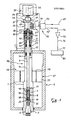
- La figure 2 représente une coupe d'un porte-outil selon l'art antérieur.
- Les figures 3 et 4 représentent, en coupe, le porte-outil selon l'invention respectivement en position de travail et en position de repos.
- La figure 5 représente une vue agrandie partielle en coupe du porte-outil.
- Figure 1 shows schematically a machine tool, such as a milling machine, provided with a tool holder.
- Figure 2 shows a section of a tool holder according to the prior art.
- Figures 3 and 4 show, in section, the tool holder according to the invention respectively in the working position and in the rest position.
- FIG. 5 represents a partial enlarged view in section of the tool holder.
Sur la figure 1, on a représenté schématiquement une fraiseuse 40 fixée au sol 41 par des vis 42. Cette fraiseuse comporte notamment un bâti 43 supportant une table de travail 44 apte à pouvoir se déplacer suivant trois coordonnées X,Y,Z, à l'aide par exemple, de moyens électriques déplaçant des vis sans fin non représentés sur la figure.In Figure 1, there is shown schematically a
Un corps supérieur 5 est solidaire du bâti 43 à l'intérieur duquel est montée une électrobroche 46 renfermant un porte-outil 50 autour d'un axe 22 et dont l'une des extrémités maintient un outil 4 tel qu'une fraise.An
Des moyens de poussée 30 représentés par un vérin électromécanique sont disposés au-dessus du corps supérieur supportant l'électrobroche, coaxialement par rapport à l'axe 22. Un boîtier de commande 53 donne les différentes instrutions nécessaires à la bonne marche de la machine-outil (déplacements de la table, rotation, arrêt de l'électrobroche,....). La table de travail 44 comporte par exemple des brides de serrage 54 permettant la fixation d'une pièce à usiner 55.Thrust means 30 represented by an electromechanical jack are disposed above the upper body supporting the electrospindle, coaxially with respect to the
La figure 2 représente une coupe d'un porte-outil selon l'art antérieur et sa description se fera en regard de celle des figures 3 et 4 qui illustrent le porte-outil selon l'invention d'une part en position de travail ou de verrouillage de l'outil (figure 3) et d'autre part en position de repos ou de déverrouillage de l'outil (figure 4).FIG. 2 represents a section of a tool holder according to the prior art and its description will be made with that of FIGS. 3 and 4 which illustrate the tool holder according to the invention on the one hand in the working position or tool locking (Figure 3) and secondly in the rest position or unlocking the tool (Figure 4).
Ce porte-outil comporte un fourreau 1 dans lequel est ménagée une percée axiale 2 débouchante définie par deux alésages coaxiaux 11 et 12 de diamètres différents, l'alésage 11 correspondant à celui de plus petit diamètre. Le changement de diamètre entre ces deux alésages 11 et 12 à l'intérieur du fourreau est représenté par un épaulement interne 14 ; l'alésage 11 de ce fourreau se termine par une extrémité conique 3 apte à recevoir la partie conique correspondante de l'outil de travail 4.This tool holder comprises a
Le fourreau 1 est intégré dans le corps 5 (représenté schématiquement sur les figures 2,3 et 4) solidaire du bâti 43 de la machine-outil. Un moteur électrique 57 est agencé entre le fourreau 1 recevant le rotor 58, et le corps 5 recevant le stator 59 de ce moteur.The
Une tige 6 est disposée dans la percée axiale 2 dont le diamètre est sensiblement équivalent à l'alésage de plus petit diamètre 11. Elle comporte à son extrémité inférieure 7, située au voisinage de l'extrémité conique 3 du fourreau, des moyens de préhension 8 définis par une bague 15 dont une première extrémité 16 est emmanchée à force dans une gorge 17 pratiquée dans la tige 6 et dont la seconde extrémité 18 est munie de griffes ou pinces élastiques 19 saillantes par rapport à l'extrémité 7 de la tige. Ces griffes 19 sont aptes à occuper deux positions précisées ci-après.A
La tige 6 comporte à son extrémité opposée 9, un filetage 10. Cette tige est apte à se déplacer axialement par rapport au fourreau 1 entre une première position de travail (figure 3) pour laquelle les griffes 19 serrent élastiquement la tête 20 de l'outil 4 et une seconde position de repos (figure 4) pour laquelle les griffes 19 sont élastiquement écartées l'une de l'autre, pour libérer la tête de l'outil. Ces griffes s'insèrent alors dans une échancrure 32 pratiquée dans la percée axiale 2, plus précisément au-dessus de l'extrémité conique 3 de l'alésage 11.The
La première position de travail correspond au verrouillage de l'outil et la seconde position de repos correspond au déverrouillage de l'outil.The first working position corresponds to the locking of the tool and the second rest position corresponds to the unlocking of the tool.
Ce porte-outil 50 comporte, en outre, des moyens de rappel élastique 25 réalisés par un empilage de rondelles de ressort de type "Belleville" ou "Schnorr" qui prend appui, d'une part, contre l'épaulement interne 14 et, d'autre part, contre un écrou de serrage 26 vissé sur le filetage 10 de l'extrémité 9 de la tige 6. Les rondelles de ressort 25 et l'écrou 26 sont disposés dans l'alésage 12 de plus grand diamètre de la percée axiale. Ces moyens 25 permettent de maintenir la tige 6 dans sa position de travail, en tirant l'outil contre l'extrémité conique 3 grâce aux moyens de préhension 8 disposés à l'extrémité 7 de la tige 6. Ces moyens 25 tendent à comprimer l'écrou de serrage 26 sous l'effet de traction développé par les rondelles de ressorts.This
Conformément à l'invention, on prévoit des moyens de contrôle permanent de la tige dans sa position de travail en mesurant pour cela, la variation de l'effort de compression de l'écrou, et plus précisément, les variations de dimension de l'écrou qui sont proportionnelles à l'effort exercé par les rondelles de ressort sur l'écrou.According to the invention, means are provided for permanent control of the rod in its working position by measuring for this, the variation in the compression force of the nut, and more precisely, the variations in dimension of the nut which are proportional to the force exerted by the spring washers on the nut.
En conséquence, si l'effort fourni par les rondelles de ressort diminue pour des raisons de fatigue, d'usure, ou de vieillissement, ces moyens de contrôle permanent détecteront ces diverses anomalies.Consequently, if the force provided by the spring washers decreases for reasons of fatigue, wear, or aging, these means of permanent control will detect these various anomalies.
Avantageusement, l'écrou de serrage 26 est réalisé en un matériau ayant des caractéristiques élastiques susceptibles de se déformer pour de faibles compressions, ce matériau pouvant être un acier.Advantageously, the tightening
Ces moyens de contrôle comprennent, par exemple, un capteur constitué par des jauges d'extensométrie résistives 60 disposées par collage dans une échancrure 27 ménagée sur l'écrou 26, des moyens d'alimentation et de transmission électrique 61, des moyens d'analyse des signaux 70 émis par les jauges et des moyens d'affichage 80 de la valeur de l'effort mesuré.These control means comprise, for example, a sensor constituted by
Du fait de la rotation autour de l'axe 22 de l'électrobroche en position de travail, de l'ensemble principalement constitué par le fourreau 1, la tige 6 e l'écrou 26, les moyens d'alimentation et de transmission 61 des signaux comportent un collecteur tournant 62 vissé dans l'extrémité de la tige 6 au moyen d'un trou taraudé 63 pratiqué sur une face 64 du collecteur, cette face venant sensiblement au contact de l'extrémité supérieure de l'écrou 26. Ce collecteur comprend succintement un rotor 65 muni de balais 66 coopérant avec des porte-balais 67 agencés sur le corps 5.Due to the rotation around the
De plus, il est relié aux jauges de contrainte 60 à l'aide de fils de connexion 68, tandis que les porte-balais 67 recevant les signaux transmis par le collecteur, sont reliés aux moyens d'analyse des signaux 70 par une liaison 71. Ces moyens d'analyse 70 comportent notamment un répartiteur 72 des signaux, sélectionnant et traitant ces derniers venant d'une part, de l'alimentation générale 69 et d'autre part, des jauges de contrainte 60, via le collecteur 62.In addition, it is connected to the
La sortie 73 du répartiteur est reliée à l'entrée 74 d'un amplificateur 75 dont la sortie 76 est connectée à l'entrée 77 des moyens d'affichage 80 constitués d'un afficheur de type numérique, par exemple à diodes électroluminescentes.The
La valeur affichée initialement est représentative de l'effort de compression de l'écrou 26 qu'exerce sur lui les rondelles de ressorts 25.The value initially displayed is representative of the compression force of the
De plus, le collecteur 62 comporte à son extrémité 84, opposée à celle venant sensiblement en regard de l'écrou 26 par sa face 64, une bague 85 comprenant une collerette 86 apte à venir au contact d'un détecteur de position 87 solidaire du corps 5 de la machine-outil, au moyen d'un vérin 30 du type électromécanique. Ce dernier est également fixé au corps 5, dans l'axe 22 de l'électrobroche 46 et est donc coaxial à l'ensemble du fourreau 1, de la tige 6, de l'écrou 26 et du collecteur 62. La tête du piston de ce vérin est en regard de l'extrémité 84 du collecteur.In addition, the
Avantageusement, les fils de connexion 68 reliant les jauges 60 au collecteur 62 sont protégés par un carter de protection 90 monté sur l'extrémité supérieure du fourreau 1 par vissage.Advantageously, the
Le fonctionnement de ce porte-outil est décrit ci-après en regard des figures 3 et 4, qui illustrent les deux positions limites opérationnelles mentionnées précédemment. L'opérateur introduit la partie conique de l'outil 4 dans l'extrémité conique 3 du fourreau 1 avec laquelle elle coopère parfaitement jusqu'au contact de la tête de l'outil contre l'extrémité 7 de la tige 6 qui se déplace ainsi vers le haut par rapport à l'axe 22. Les moyens de préhension 8, notamment les griffes 19 quittent l'échancrure 32 ménagée dans la percée axiale 2 et se referment sur la tête de la fraise en l'emprisonnant du fait du changement de section entre l'échancrure 32 et le premier alésage 11. Dans une opération de réglage préalable, un opérateur visse l'écrou de serrage 26 au moyen d'une clé dynamométrique autour du filetage 10 de la tige 6 jusqu'à une certaine valeur Vo déterminée préalablement par calcul, entrainant dans son mouvement hélicoïdal les rondelles de ressort 25 en compression. La valeur de cet effort de serrage appliqué sur l'écrou est représentative de la résistance mécanique des rondelles de ressort.The operation of this tool holder is described below with reference to Figures 3 and 4, which illustrate the two operational limit positions mentioned above. The operator introduces the conical part of the tool 4 into the
L'opérateur consulte la valeur Vo indiquée et délivrée par l'afficheur numérique 80 recevant les informations électriques en provenance des jauges de contrainte 60 disposées par collage sur l'écrou et des moyens d'analyse 70 et de transmission 61 de ce signaux. Préalablement, ces divers moyens auront été étalonnés.The operator consults the value Vo indicated and delivered by the
L'opérateur, après avoir effectué les différents réglages pour l'usinage de la pièce, met en action le moteur 57 de l'électrobroche 46 entrainant de ce fait l'ensemble du fourreau 1, de la tige 6, de l'écrou 26 du collecteur 62 et de l'outil 4 en rotation autour de l'axe 22.The operator, after having made the various adjustments for the machining of the part, activates the
L'opérateur peut contrôler sur l'afficheur numérique 80, une éventuelle variation de la valeur Vo affichée initialement au moyen des informations transmises par les jauges d'extensométrie 60, mesurant en permanence la compression et la dilatation de la partie de l'écrou où elles sont collées et représentatives de l'effort exercé sur la face d'appui de l'écrou de serrage 26 par l'empilage de rondelles 25.The operator can control on the
Bien évidemment, la valeur affichée Vo est une valeur maximale de tarage initial, qui ne peut que décroître par suite de la fatigue et l'usure mécanique des rondelles de ressort, dont on mesure justement la diminution éventuelle de leur effort.Obviously, the displayed value Vo is a maximum initial setting value, which can only decrease as a result of the fatigue and mechanical wear of the spring washers, of which the possible reduction in their effort is precisely measured.
Dans le cas d'une perte d'efficacité de ces rondelles 25 (fatigue, amorces de criques, etc...), l'opérateur est averti par l'afficheur numérique 80, qui délivre une valeur Vo-v, qui peut être couplée à un dispositif sonore ou lumineux optimisant la sécurité. Dans le cas d'une chute brutale de l'effort fourni par les rondelles de ressort, autorisant une décompression de l'écrou 26 importante, la valeur transmise par les jauges à l'afficheur indique une valeur minimale Vo-v1 dépassant un seuil de tolérance admis, en déclenchant un arrêt immédiat de la broche.In the event of a loss of efficiency of these washers 25 (fatigue, crack initiations, etc.), the operator is warned by the
Il est important de préciser, non seulement que ces moyens de contrôle permanent sont avantageux pour prévenir d'une mauvaise fixation de l'outil lors de la rotation de l'électrobroche, mais également lors de l'arrêt même prolongé de la machine-outil.It is important to specify, not only that these permanent control means are advantageous to prevent improper attachment of the tool during the rotation of the electrospindle, but also during the even prolonged stop of the machine tool .
L'opérateur, en arrivant à son poste de travail, peut constater que l'afficheur numérique délivre une valeur inférieure à celle de référence (complétée éventuellement par un signal sonore ou lumineux) et intervenir en conséquence pour faire changer les rondelles de ressort.The operator, arriving at his workstation, can see that the digital display delivers a value lower than that of the reference (possibly supplemented by an audible or light signal) and intervene accordingly to change the spring washers.
Ce changement s'effectue, électrobroche à l'arrêt, en retirant le carter de protection 90, puis en dévissant à l'aide d'une clé dynamométrique l'écrou de serrage 26.This change is made with the electrospindle stopped, by removing the
Le montage de l'écrou contre le nouveau jeu de rondelles de ressort dans l'alésage 12 de la percée axiale 2 du fourreau 1 doit être préalablement soumis au contrôle de son étalonnage indiquant par exemple une valeur 0 dans l'afficheur 80. Le serrage de l'écrou 26 s'effectue à l'aide de la clé jusqu'à atteindre la valeur de tarage initial Vo.The mounting of the nut against the new set of spring washers in the
Le démontage de l'outil selon l'invention s'effectue, à l'aide du vérin électromécanique 30 actionné par l'opérateur et dont le piston vient en contact de l'extrémité 84 du collecteur 62 entrainant vers le bas l'ensemble de l'écrou 26, de la tige 6, et de l'outil 4 en comprimant les rondelles de ressort 25.Disassembly of the tool according to the invention is carried out, using the
Bien évidemment, la force délivrée par le vérin est supérieure à celle exercée par les rondelles de ressort.Obviously, the force delivered by the jack is greater than that exerted by the spring washers.
Ainsi, les griffes 19 des moyens de préhension 8 s'écartent progressivement retrouvant par élasticité leur position d'origine pour se loger dans l'échancrure 32 du fourreau 1 qui reste fixe en translation par rapport à l'axe 22. A ce moment là, l'opérateur retire l'outil 4 du porte-outil pour procéder par exemple à un changement d'outillage. Préalablement à l'intervention de l'opérateur, la collerette 86 de la bague 85 liée au collecteur 62 est, lors de la descente de l'ensemble mentionné précédemment, entrée en contact du détecteur de position 87 solidaire du corps 5 provoquant ainsi l'immobilisation en rotation de l'électrobroche tant que le porte-outil est en position de déverrouillage.Thus, the
Au regard de ce qui a été décrit ci-dessus, les avantages procurés par un tel porte-outil comportant des moyens de contrôle permanent, optimisent non seulement la qualité du travail réalisé évitant notamment les rebuts de pièces, et les opérations de maintenance, mais également la sécurité des opérateurs.In view of what has been described above, the advantages provided by such a tool holder comprising permanent control means, not only optimize the quality of the work carried out, in particular avoiding scrap parts, and maintenance operations, but also operator safety.
On pourrait concevoir, sans sortir du cadre de l'invention, de connecter directement les jauges de contrainte aux moyens d'analyses des signaux sans passer par un collecteur dans le cas d'une machine-outil dont l'outil travaillerait en translation.It would be conceivable, without departing from the scope of the invention, to directly connect the strain gauges to the signal analysis means without passing through a collector in the case of a machine tool whose tool would work in translation.
Claims (10)
- un fourreau (1) dans lequel est ménagée une percée axiale (2) débouchante, ledit fourreau étant monté dans un corps (5) solidaire de la machine-outil ;
- une tige (6) disposée dans ladite percée axiale (2) du fourreau, une première extrémité (7) de ladite tige comportant des moyens de préhension (8) apte à maintenir une tête d'outil (4), la second extrémité (9) de la tige comportant un filetage (10), cette tige étant apte à se déplacer axialement par rapport audit fourreau entre une position de travail avec verrouillage de l'outil, et une position de repos avec déverrouillage de l'outil ;
- des moyens de rappel élastique (25) axial, prenant appui d'une part, contre ledit fourreau (1) et d'autre part, contre un écrou (26) vissé sur le filetage (10) de ladite tige et permettant de maintenir la tige (6) dans sa position de travail,
caractérisé par le fait qu'il comporte des moyens de contrôle permanent de la tige dans sa position de travail, ces moyens comprenant au moins un capteur (60) agencé sur ledit écrou (26), des moyens d'alimentation et de transmission électrique (61) dudit capteur (60), des moyens d'analyse des signaux (70) émis par ledit capteur, et des moyens d'affichage (80) de ces signaux, pour détecter la variation de la déformation élastique de l'écrou (26) sous l'action des moyens de rappel élastique (25).1 - Safety tool holder for machine tool (40) comprising:
- A sheath (1) in which an axial opening (2) is formed, said sheath being mounted in a body (5) integral with the machine tool;
- a rod (6) disposed in said axial opening (2) of the sheath, a first end (7) of said rod comprising gripping means (8) capable of holding a tool head (4), the second end ( 9) of the rod comprising a thread (10), this rod being able to move axially relative to said sheath between a working position with locking of the tool, and a rest position with unlocking of the tool;
- axial elastic return means (25), bearing on the one hand, against said sheath (1) and on the other hand, against a nut (26) screwed onto the thread (10) of said rod and making it possible to maintain the rod (6) in its working position,
characterized by the fact that it comprises means for permanent control of the rod in its working position, these means comprising at least one sensor (60) arranged on said nut (26), means of supply and electrical transmission ( 61) of said sensor (60), means for analyzing the signals (70) emitted by said sensor, and display means (80) of these signals, for detecting the variation in the elastic deformation of the nut (26 ) under the action of the elastic return means (25).
caractérisé par le fait que les moyens d'alimentation et de transmission des signaux (61) sont constitués par un collecteur (62) tournant comportant principalement un rotor (65), des balais (66) et porte-balais (67), alimentant lesdites jauges (60) à l'aide de connexions électriques, et transmettant les signaux reçus aux moyens d'analyses (70).3 - Tool holder according to one of the preceding claims in which the sleeve (1) and the rod (6) are coaxial with each other and able to be driven in rotation,
characterized in that the means for supplying and transmitting the signals (61) consist of a rotating collector (62) mainly comprising a rotor (65), brushes (66) and brush holder (67), supplying said said gauges (60) using electrical connections, and transmitting the received signals to the analysis means (70).
caractérisé par le fait que ledit écrou (26) est réalisé en un matériau ayant des caractéristiques élastiques, susceptible de se déformer pour de faibles compressions.7 - Safety tool holder according to one of claims 1 to 6,
characterized in that said nut (26) is made of a material having elastic characteristics, capable of being deformed for low compressions.
caractérisé par le fait qu'il comporte un carter de protection (90) fixé sur ledit fourreau (1) assurant la protection des fils de connexion (68) des jauges d'extensométrie (60) au collecteur (62).9 - Safety tool holder according to one of claims 1 to 7,
characterized by the fact that it comprises a protective casing (90) fixed to said sheath (1) ensuring the protection of the connection wires (68) of the strain gauges (60) to the collector (62).
caractérisée en ce qu'elle comporte au moins un porteoutil tel que défini sous l'une des revendications 1 à 9.10 - Machine tool
characterized in that it comprises at least one tool holder as defined in one of claims 1 to 9.
Applications Claiming Priority (2)
| Application Number | Priority Date | Filing Date | Title |
|---|---|---|---|
| FR8515201 | 1985-10-14 | ||
| FR8515201A FR2588492B1 (en) | 1985-10-14 | 1985-10-14 | SAFETY TOOL HOLDER FOR MACHINE TOOL |
Publications (2)
| Publication Number | Publication Date |
|---|---|
| EP0221802A1 true EP0221802A1 (en) | 1987-05-13 |
| EP0221802B1 EP0221802B1 (en) | 1989-04-05 |
Family
ID=9323801
Family Applications (1)
| Application Number | Title | Priority Date | Filing Date |
|---|---|---|---|
| EP86402184A Expired EP0221802B1 (en) | 1985-10-14 | 1986-10-03 | Safety tool holder for a machine tool |
Country Status (7)
| Country | Link |
|---|---|
| US (1) | US4708547A (en) |
| EP (1) | EP0221802B1 (en) |
| JP (1) | JPS6294207A (en) |
| CA (1) | CA1277490C (en) |
| DE (1) | DE3662655D1 (en) |
| ES (1) | ES2007565B3 (en) |
| FR (1) | FR2588492B1 (en) |
Cited By (4)
| Publication number | Priority date | Publication date | Assignee | Title |
|---|---|---|---|---|
| EP0258989A1 (en) * | 1986-07-24 | 1988-03-09 | Seiko Seiki Kabushiki Kaisha | Clamping device in a machine tool spindle |
| EP0356636A2 (en) * | 1988-09-02 | 1990-03-07 | Kelch Gmbh + Co. | Pulling force measuring device for tool-clamping devices |
| FR2695850A1 (en) * | 1992-09-23 | 1994-03-25 | Snecma | Drive for rotating machine tool allowing tool changing by robot - uses spring force to close clamp that locks jaws onto tool shaft and remotely operated push-rod to act against spring. |
| WO1998004377A2 (en) * | 1996-07-25 | 1998-02-05 | Ima Montagetechnik Gmbh | Work spindle for a machine tool |
Families Citing this family (17)
| Publication number | Priority date | Publication date | Assignee | Title |
|---|---|---|---|---|
| DE3750840D1 (en) * | 1986-11-04 | 1995-01-19 | Fritz Kruesi Maschinenbau | Device for processing a workpiece made of wood, in particular wooden beams. |
| US5078558A (en) * | 1990-02-16 | 1992-01-07 | Hitachi Seiko, Ltd. | Low mass spindle and Z-axis unit |
| JP2001315010A (en) * | 2000-05-08 | 2001-11-13 | Mori Seiki Co Ltd | Machine tool |
| JP4772991B2 (en) * | 2001-06-22 | 2011-09-14 | オークマ株式会社 | Machine tool spindle equipment |
| CN100506471C (en) * | 2002-04-20 | 2009-07-01 | 瑞尼斯豪公司 | Machine adaptation |
| ATE390243T1 (en) * | 2002-09-13 | 2008-04-15 | Hermle Berthold Maschf Ag | SPINDLE HEAD FOR A MACHINE TOOL |
| GB0311852D0 (en) * | 2003-05-22 | 2003-06-25 | Westwind Air Bearings Ltd | Rotary tool holder assemblies |
| DE102004011738B4 (en) * | 2004-03-03 | 2010-01-07 | Michael Weinig Ag | Device with a release unit for actuating a clamping device for tools |
| US6951256B1 (en) * | 2004-04-24 | 2005-10-04 | Ru Song Xiao | Machine tool having coaxial driving device |
| DE102004026438B4 (en) * | 2004-05-29 | 2009-04-02 | Ott-Jakob Gmbh & Co. Spanntechnik Kg | jig |
| DE102004051031B3 (en) * | 2004-10-20 | 2006-04-27 | Ott-Jakob Gmbh & Co. Spanntechnik Kg | jig |
| RU2357345C2 (en) * | 2006-10-11 | 2009-05-27 | Шлюмбергер Текнолоджи Б.В. | Submersible direct current motor |
| DE102007007389B3 (en) * | 2007-02-12 | 2008-07-03 | Ott-Jakob Spanntechnik Gmbh | Clamping device for clamping tool or tool holder to machine tool, has sensor assigned to transponder arrangements with stator ring and stator that is adjustable by stroke movement of cone within ring for wireless data and energy transfer |
| DE102012005614B4 (en) | 2012-03-22 | 2013-10-17 | Matthias Brenneis | Sensory connection element and manufacturing method |
| JP5894837B2 (en) * | 2012-04-02 | 2016-03-30 | トーヨーエイテック株式会社 | Machine tool clamping device |
| JP6492502B2 (en) * | 2014-10-03 | 2019-04-03 | 株式会社ジェイテクト | Machine tool spindle equipment |
| DE102020126006A1 (en) * | 2020-10-05 | 2022-04-07 | Sterman Technische Systeme Gmbh | Clamping device, spindle arrangement and machine tool |
Citations (5)
| Publication number | Priority date | Publication date | Assignee | Title |
|---|---|---|---|---|
| US3201977A (en) * | 1961-02-20 | 1965-08-24 | Kutsay Ali Umit | Strain gauge |
| FR1451525A (en) * | 1965-07-22 | 1966-01-07 | Forest & Cie | Device for locking a conical tool holder in a nose of a machine tool rotating spindle |
| FR2518749A1 (en) * | 1981-12-23 | 1983-06-24 | Forkardt Paul Gmbh | CLAMPING FORCE SENSOR FOR ROTARY CLAMPING DEVICES |
| DE3212761A1 (en) * | 1982-04-06 | 1983-10-13 | Paul Forkardt GmbH & Co KG, 4000 Düsseldorf | CIRCULAR CLAMPING DEVICE |
| DE3408310A1 (en) * | 1984-03-07 | 1984-10-04 | Eberhard Dipl.-Ing. 6301 Wettenberg Seidel | Measuring device for separately measuring the axial clamping force and the fastening torque and the components of the latter arising from the thread friction and head friction of a bolted joint without superposition of tensile and torsional stress |
Family Cites Families (7)
| Publication number | Priority date | Publication date | Assignee | Title |
|---|---|---|---|---|
| US3520228A (en) * | 1967-04-10 | 1970-07-14 | Giddings & Lewis | Spindle orienting and drawbolt malfunction sensing machine tool control system |
| US3603203A (en) * | 1970-01-12 | 1971-09-07 | Pratt & Whitney Inc | Pneumatic tool-sensing system for machine tool |
| SU524618A1 (en) * | 1975-01-20 | 1976-08-15 | Device for clamping the tool in the machine spindle | |
| JPS5245784A (en) * | 1975-10-09 | 1977-04-11 | Howa Mach Ltd | Unclampdevice for tool |
| US4303360A (en) * | 1980-02-29 | 1981-12-01 | Giddings & Lewis, Inc. | Power drawfinger system for machine tool spindle |
| JPS5924944A (en) * | 1982-07-27 | 1984-02-08 | Yamazaki Mazak Corp | Device for measuring tool holding force |
| JPS5973252A (en) * | 1982-10-20 | 1984-04-25 | Inoue Japax Res Inc | Tool and tool attaching device |
-
1985
- 1985-10-14 FR FR8515201A patent/FR2588492B1/en not_active Expired
-
1986
- 1986-10-03 ES ES86402184T patent/ES2007565B3/en not_active Expired
- 1986-10-03 DE DE8686402184T patent/DE3662655D1/en not_active Expired
- 1986-10-03 EP EP86402184A patent/EP0221802B1/en not_active Expired
- 1986-10-09 JP JP61239427A patent/JPS6294207A/en active Pending
- 1986-10-14 US US06/918,394 patent/US4708547A/en not_active Expired - Fee Related
- 1986-10-14 CA CA000520367A patent/CA1277490C/en not_active Expired - Fee Related
Patent Citations (5)
| Publication number | Priority date | Publication date | Assignee | Title |
|---|---|---|---|---|
| US3201977A (en) * | 1961-02-20 | 1965-08-24 | Kutsay Ali Umit | Strain gauge |
| FR1451525A (en) * | 1965-07-22 | 1966-01-07 | Forest & Cie | Device for locking a conical tool holder in a nose of a machine tool rotating spindle |
| FR2518749A1 (en) * | 1981-12-23 | 1983-06-24 | Forkardt Paul Gmbh | CLAMPING FORCE SENSOR FOR ROTARY CLAMPING DEVICES |
| DE3212761A1 (en) * | 1982-04-06 | 1983-10-13 | Paul Forkardt GmbH & Co KG, 4000 Düsseldorf | CIRCULAR CLAMPING DEVICE |
| DE3408310A1 (en) * | 1984-03-07 | 1984-10-04 | Eberhard Dipl.-Ing. 6301 Wettenberg Seidel | Measuring device for separately measuring the axial clamping force and the fastening torque and the components of the latter arising from the thread friction and head friction of a bolted joint without superposition of tensile and torsional stress |
Cited By (6)
| Publication number | Priority date | Publication date | Assignee | Title |
|---|---|---|---|---|
| EP0258989A1 (en) * | 1986-07-24 | 1988-03-09 | Seiko Seiki Kabushiki Kaisha | Clamping device in a machine tool spindle |
| EP0356636A2 (en) * | 1988-09-02 | 1990-03-07 | Kelch Gmbh + Co. | Pulling force measuring device for tool-clamping devices |
| EP0356636A3 (en) * | 1988-09-02 | 1991-04-03 | Gmbh + Co. Kelch | Pulling force measuring device for tool-clamping devices |
| FR2695850A1 (en) * | 1992-09-23 | 1994-03-25 | Snecma | Drive for rotating machine tool allowing tool changing by robot - uses spring force to close clamp that locks jaws onto tool shaft and remotely operated push-rod to act against spring. |
| WO1998004377A2 (en) * | 1996-07-25 | 1998-02-05 | Ima Montagetechnik Gmbh | Work spindle for a machine tool |
| WO1998004377A3 (en) * | 1996-07-25 | 1998-03-26 | Ima Montagetechnik Gmbh | Work spindle for a machine tool |
Also Published As
| Publication number | Publication date |
|---|---|
| FR2588492B1 (en) | 1989-05-26 |
| EP0221802B1 (en) | 1989-04-05 |
| US4708547A (en) | 1987-11-24 |
| JPS6294207A (en) | 1987-04-30 |
| ES2007565B3 (en) | 1989-08-01 |
| CA1277490C (en) | 1990-12-11 |
| FR2588492A1 (en) | 1987-04-17 |
| DE3662655D1 (en) | 1989-05-11 |
Similar Documents
| Publication | Publication Date | Title |
|---|---|---|
| EP0221802B1 (en) | Safety tool holder for a machine tool | |
| EP1120190B1 (en) | Pneumatic machine tool | |
| FR2643845A3 (en) | SCREWDRIVER | |
| FR2582243A1 (en) | ANOMALY DETECTOR OF A TOOL | |
| FR2743449A1 (en) | PORTABLE TOOL FOR CRIMPING CONNECTION PIN ON ELECTRICAL CONDUCTORS | |
| FR2468438A1 (en) | TOOL HOLDER DEVICE FOR MACHINE TOOLS | |
| EP1945405B1 (en) | Method and device for adjusting the fitting depth of a tool in a tool-holder | |
| FR2474375A1 (en) | ||
| FR2534515A1 (en) | Vibrating tool holder drive by flexible shaft | |
| FR2583520A1 (en) | MOTOR VEHICLE SPEED DETECTOR | |
| EP1252969B1 (en) | Anti - shock screw unit | |
| EP0247939A1 (en) | Machine for the automatic setting of tool length and diameter | |
| FR2776858A1 (en) | HOLDING, POSITIONING, OR CLAMPING DEVICE, ELECTRICALLY ACTUATED | |
| EP1157766B1 (en) | Bar feeder | |
| EP2998835A1 (en) | Data input device and braking means thereof | |
| EP1592534B1 (en) | Device for grinding ophthalmic lenses comprising improved means of clamping the glass blank for grinding | |
| EP1890840A1 (en) | Calibration tool and milling machine comprising same | |
| FR2543041A1 (en) | Method and installation for tightening a connection of the screw type, with control of the mechanical tensile force applied to the screw | |
| EP0569288B1 (en) | Helicopter tail rotor with a detector of exceeding a translational stress threshold in the pitch control | |
| FR2814765A1 (en) | CONTROL SYSTEM FOR THE GRINDING OF A GRINDING MACHINE IN PARTICULAR OF RAILS | |
| FR2842449A1 (en) | Assembly tool with data supply device, especially torque wrench, has interface providing data output for recording e.g. torque data | |
| BE1003342A5 (en) | Load limiting device for lifting appliances or other industrialapplications, and process for adjusting it | |
| EP1000710B1 (en) | Method of mesuring and/or controlling in a fastening device including a hydropneumatic impulse screw driver | |
| EP1926573B1 (en) | Torque wrench | |
| FR2692510A1 (en) | Tool holder speed adaptor for fixed machine tool - is fastened to machine tool spindle with bearings and rotation preventer including pulley drive increasing speed to adaptor tool |
Legal Events
| Date | Code | Title | Description |
|---|---|---|---|
| PUAI | Public reference made under article 153(3) epc to a published international application that has entered the european phase |
Free format text: ORIGINAL CODE: 0009012 |
|
| AK | Designated contracting states |
Kind code of ref document: A1 Designated state(s): BE DE ES GB IT NL |
|
| 17P | Request for examination filed |
Effective date: 19870529 |
|
| 17Q | First examination report despatched |
Effective date: 19880627 |
|
| GRAA | (expected) grant |
Free format text: ORIGINAL CODE: 0009210 |
|
| RAP1 | Party data changed (applicant data changed or rights of an application transferred) |
Owner name: SOCIETE NATIONALE INDUSTRIELLE AEROSPATIALE SOCIET |
|
| AK | Designated contracting states |
Kind code of ref document: B1 Designated state(s): BE DE ES GB IT NL |
|
| RAP2 | Party data changed (patent owner data changed or rights of a patent transferred) |
Owner name: AEROSPATIALE SOCIETE NATIONALE INDUSTRIELLE |
|
| REF | Corresponds to: |
Ref document number: 3662655 Country of ref document: DE Date of ref document: 19890511 |
|
| GBT | Gb: translation of ep patent filed (gb section 77(6)(a)/1977) | ||
| ITF | It: translation for a ep patent filed |
Owner name: MODIANO & ASSOCIATI S.R.L. |
|
| BECN | Be: change of holder's name |
Effective date: 19890405 |
|
| PLBE | No opposition filed within time limit |
Free format text: ORIGINAL CODE: 0009261 |
|
| STAA | Information on the status of an ep patent application or granted ep patent |
Free format text: STATUS: NO OPPOSITION FILED WITHIN TIME LIMIT |
|
| 26N | No opposition filed | ||
| ITTA | It: last paid annual fee | ||
| PGFP | Annual fee paid to national office [announced via postgrant information from national office to epo] |
Ref country code: GB Payment date: 19921001 Year of fee payment: 7 |
|
| PGFP | Annual fee paid to national office [announced via postgrant information from national office to epo] |
Ref country code: ES Payment date: 19921005 Year of fee payment: 7 |
|
| PGFP | Annual fee paid to national office [announced via postgrant information from national office to epo] |
Ref country code: NL Payment date: 19921031 Year of fee payment: 7 |
|
| PGFP | Annual fee paid to national office [announced via postgrant information from national office to epo] |
Ref country code: DE Payment date: 19921104 Year of fee payment: 7 |
|
| PGFP | Annual fee paid to national office [announced via postgrant information from national office to epo] |
Ref country code: BE Payment date: 19921208 Year of fee payment: 7 |
|
| PG25 | Lapsed in a contracting state [announced via postgrant information from national office to epo] |
Ref country code: GB Effective date: 19931003 |
|
| PG25 | Lapsed in a contracting state [announced via postgrant information from national office to epo] |
Ref country code: ES Free format text: LAPSE BECAUSE OF THE APPLICANT RENOUNCES Effective date: 19931004 |
|
| PG25 | Lapsed in a contracting state [announced via postgrant information from national office to epo] |
Ref country code: BE Effective date: 19931031 |
|
| BERE | Be: lapsed |
Owner name: AEROSPATIALE SOC. NATIONALE INDUSTRIELLE Effective date: 19931031 |
|
| PG25 | Lapsed in a contracting state [announced via postgrant information from national office to epo] |
Ref country code: NL Effective date: 19940501 |
|
| GBPC | Gb: european patent ceased through non-payment of renewal fee |
Effective date: 19931003 |
|
| NLV4 | Nl: lapsed or anulled due to non-payment of the annual fee | ||
| PG25 | Lapsed in a contracting state [announced via postgrant information from national office to epo] |
Ref country code: DE Effective date: 19940701 |
|
| REG | Reference to a national code |
Ref country code: ES Ref legal event code: FD2A Effective date: 19991007 |
|
| PG25 | Lapsed in a contracting state [announced via postgrant information from national office to epo] |
Ref country code: IT Free format text: LAPSE BECAUSE OF NON-PAYMENT OF DUE FEES;WARNING: LAPSES OF ITALIAN PATENTS WITH EFFECTIVE DATE BEFORE 2007 MAY HAVE OCCURRED AT ANY TIME BEFORE 2007. THE CORRECT EFFECTIVE DATE MAY BE DIFFERENT FROM THE ONE RECORDED. Effective date: 20051003 |