EP0221322A2 - Process for applying a protective covering to a printing cylinder, and device for carrying out the process - Google Patents
Process for applying a protective covering to a printing cylinder, and device for carrying out the process Download PDFInfo
- Publication number
- EP0221322A2 EP0221322A2 EP86113160A EP86113160A EP0221322A2 EP 0221322 A2 EP0221322 A2 EP 0221322A2 EP 86113160 A EP86113160 A EP 86113160A EP 86113160 A EP86113160 A EP 86113160A EP 0221322 A2 EP0221322 A2 EP 0221322A2
- Authority
- EP
- European Patent Office
- Prior art keywords
- plate
- cylinder
- pit
- film
- pressure roller
- Prior art date
- Legal status (The legal status is an assumption and is not a legal conclusion. Google has not performed a legal analysis and makes no representation as to the accuracy of the status listed.)
- Ceased
Links
Images


Classifications
-
- B—PERFORMING OPERATIONS; TRANSPORTING
- B41—PRINTING; LINING MACHINES; TYPEWRITERS; STAMPS
- B41F—PRINTING MACHINES OR PRESSES
- B41F13/00—Common details of rotary presses or machines
- B41F13/08—Cylinders
-
- B—PERFORMING OPERATIONS; TRANSPORTING
- B41—PRINTING; LINING MACHINES; TYPEWRITERS; STAMPS
- B41F—PRINTING MACHINES OR PRESSES
- B41F27/00—Devices for attaching printing elements or formes to supports
-
- B—PERFORMING OPERATIONS; TRANSPORTING
- B41—PRINTING; LINING MACHINES; TYPEWRITERS; STAMPS
- B41N—PRINTING PLATES OR FOILS; MATERIALS FOR SURFACES USED IN PRINTING MACHINES FOR PRINTING, INKING, DAMPING, OR THE LIKE; PREPARING SUCH SURFACES FOR USE AND CONSERVING THEM
- B41N6/00—Mounting boards; Sleeves Make-ready devices, e.g. underlays, overlays; Attaching by chemical means, e.g. vulcanising
-
- Y—GENERAL TAGGING OF NEW TECHNOLOGICAL DEVELOPMENTS; GENERAL TAGGING OF CROSS-SECTIONAL TECHNOLOGIES SPANNING OVER SEVERAL SECTIONS OF THE IPC; TECHNICAL SUBJECTS COVERED BY FORMER USPC CROSS-REFERENCE ART COLLECTIONS [XRACs] AND DIGESTS
- Y10—TECHNICAL SUBJECTS COVERED BY FORMER USPC
- Y10T—TECHNICAL SUBJECTS COVERED BY FORMER US CLASSIFICATION
- Y10T156/00—Adhesive bonding and miscellaneous chemical manufacture
- Y10T156/10—Methods of surface bonding and/or assembly therefor
- Y10T156/1002—Methods of surface bonding and/or assembly therefor with permanent bending or reshaping or surface deformation of self sustaining lamina
- Y10T156/1028—Methods of surface bonding and/or assembly therefor with permanent bending or reshaping or surface deformation of self sustaining lamina by bending, drawing or stretch forming sheet to assume shape of configured lamina while in contact therewith
- Y10T156/1033—Flexible sheet to cylinder lamina
Definitions
- the invention relates to a method for applying a protective coating to a printing couple cylinder according to the preamble of claim 1 and devices for carrying out the method.
- the adhesive on the film (2) is intended to bring about an immediate bond as soon as it comes into contact with a counter layer or surface, it not being absolutely essential that the maximum adhesive effect be achieved immediately.
- Such adhesives are referred to as so-called “single-sided contact adhesives”.
- the adhesive layer on the film (2) must be extremely homogeneous and have a uniform thickness.
- the film (2) or the adhesive layers located on this on both sides are covered by a protective layer S, for example also made of a thin film material, so that the adhesive film can be stored on a winding roll.
- the plate (1) shown in FIG. 2 is first to be coated with a film (2), the plate ends (3, 4) to be inserted into the cylinder pits being glued in different ways. While the plate end (3) and the remaining plate (1) covering the cylinder jacket are covered with the film (2), the other plate end (4) is not covered with the film (2).
- a film-free area or space (5) is preferably provided on the plate (1), which, as will be explained in more detail later, comes to lie above the leading edge of the pit.
- the film (2) is pulled off a supply roll (6) and rolled onto the flexible plate (1) without bubbles and with even pressure using an elastic pressure roller (7).
- FIGS. 3 to 6 show a bending device with which the plate (1) shown in FIG. 2 can be angled at the two ends (3, 4) in order to later use the ends (3, 4) in accordance with the invention
- the plate (1) is bent to the exact edge using the bending device shown in FIGS. 3 to 6.
- This comprises side walls (9, 10), between which a cylinder (11) is mounted, which has a relatively wide pit (12).
- the width and diameter of the cylinder (11) serving as the bending shape are therefore precisely matched to the size of the printing unit cylinder to be covered with the plate (1).
- the insert strip (16) shown in FIG. 4 which has holes (17), can be screwed into threaded holes in the bottom of the pit (12) using screws, not shown.
- a pulling and fixing bar (22) according to FIG. 6 and a fixing bar (19) between the support bar (13) and the pit wall (14) ) can be used according to Fig. 5.
- the fixing bar (19) and the pulling and fixing bar (22) have through holes (20 and 23 respectively) and eccentric holes (21 and 24).
- eccentrics are used, for example, with an Allen key, which can be rotated out of the side faces of the strips (19, 22) during rotation.
- the plate end (3) is first inserted into the pit (12) so that it comes into contact with the pit wall (14).
- the fixing bar (19) is then inserted between the pit wall (14) and the support bar (13), this being fixed to the pit floor by means of screws and by means of rotatable eccentrics in the eccentric holes (21) against the pit wall (14) or against that on the pit wall (14) abutting end (3) of the plate (1) is pressed so that the plate end (3) is exactly fixed.
- an elastic pinch roller (25) which is also rotatably mounted between the side walls (10, 11), is used to precisely bend the end defined in the manner described above, here (3) reached the plate (1) and, when the cylinder (11) is turned further, the plate (5) is rolled onto the jacket of the cylinder (11) until the other plate end, here (4), is bent over by the pressure roller (25) and into the pit (12) is pushed into it.
- the plate end (4) is placed against the pit wall (15) and then between the insert bar (16), which is by means of the holes (17) and the threaded holes (18) have already been fastened in the pit (12), and the pit wall (15) has inserted the pulling and fixing strip (22).
- the end (4) is now pressed completely against the pit wall (25) by means of rotatable eccentrics, not shown, in the eccentric holes (24), after which the pulling and pulling screws are inserted through the holes (23) into the threaded holes (18)
- Fixing strip (22) is pressed downwards against the pit wall (15) or the plate end (4) resting thereon, ie towards the pit floor.
- At least the side of the pulling and fixing strip (22) abutting the plate end (4) should be roughened, for example corrugated, so that the pulling action which acts on the end (4) of the plate is increased.
- a similar corrugation or roughening can also be carried out on the corresponding side of the fixing strip (19).
- the cylinder (11) has cutting grooves (26, 27) on both sides, into which disk-shaped knives (28, 29) engage.
- the plate (1) on the cylinder (11) is cut to the required width precisely and without distortion by appropriate adjustment of the knives (28, 29).
- the plate (2) bent on the device according to FIG. 3 can now be removed from the cylinder (11) by loosening the parts (16, 19, 22) and brought back into the position shown in FIG.
- the pre-bent plate (1) can be subsequently applied to a cylinder in a printing press, which will be described in more detail below.
- FIGS. 8 and 9 wherein no pre-bending or pre-bending is required.
- the method described in connection with FIGS. 8 and 9 is preferably used in the production of a printing group cylinder, while the method shown in FIG. 10 is suitable for applying the plate (1) in the installed state of the printing group cylinders.
- the cylinder (30) shown in FIGS. 8 and 9, for example a blanket cylinder has a pit (31) with channels (32, 33), on the walls (34, 35) of which the plate ends 37, 38) of a flexible plate ( 36), which is coated like the plate (1) according to FIG. 2.
- the plate (36) is rolled onto the cylinder (30) using a pressure roller (39) which is rotatably attached to the jacket of the cylinder (30).
- the cylinder (30) also rotates in the direction of the arrow in printing operation.
- the end (37) of the plate (36) covered with the film (2) is placed against the pit wall (34), after which a fixing strip (40) is inserted into the pit channel (32) and at the bottom of the Pit channel (32) is screwed.
- the fixing bar (40) is preferably constructed similarly like the fixing bar (19) according to Fig. 5. Then, while rotating the cylinder (30), the plate (36) is glued onto the jacket of the cylinder (30) by the pressure roller (39), the corresponding protective film S having to be removed successively. This process continues until, according to the position shown in FIG.
- the pressure roller (39) folds the rear end (38) of the plate (36) at the trailing edge of the pit and at least partially the rear end (38) into the pit (31 ) pushes in.
- the protective film S is not immediately removed from the adhesive layer, since after the end (38) has been bent, the roller (39) or the cylinder on the trailing edge (52) again in the opposite direction is rotated, after which, as indicated by the broken line in FIG. 8, the end (38) is inserted into the pit channel (33).
- the plate (42) is finally rolled onto the jacket of the cylinder (30) to the trailing edge of the pit (52) with the help of the pressure roller (39), removing the protective film S, ie glued on.
- the plate (36) is bent exactly around the trailing edge of the pit (52).
- a pulling and fixing strip (41) is inserted, which is constructed in accordance with the pulling and fixing strip (22) according to FIG.
- either the lower side of the end (38) of the plate (36) or the pit wall (35) was coated with a liquid adhesive or a pressure-sensitive adhesive which, when the end (38) was in contact with the pit wall (35) initially allows a displacement of the end (38) on the pit wall (35). It is thereby achieved in the manner according to the invention that when the pulling and fixing strip (41) is pulled in or screwed in, the plate (36) or the end (38) lies precisely and extends along the trailing edge of the pit (52) and the pit wall (35 ) he follows.
- the plate (36) was also guided exactly around the leading pit edge (51), it being extremely advantageous that the area above the leading pit edge (51), in the direction of rotation of the printing unit cylinder, was free of the adhesive film is (see area 5). As a result, no material accumulation on the Pit edge (51) occur during the fold, which would otherwise have an adverse effect on the life of the coating and a fold would not be possible exactly.
- FIG. 10 schematically shows rubber cylinders (43, 44) with associated plate cylinders (45, 46), as are used in conventional web-fed rotary printing presses.
- a flexible plate with a built-in printing unit cylinder here a blanket cylinder (44)
- the plate (1) angled according to FIG. 7 is inserted into the pit with the end (3) covered with film (2) and fixed in the manner already described in connection with FIGS. 8 and 3 by means of a fixing piece or fixing strip.
- the two rubber cylinders are slowly rotated and a deformable, thus elastic pressure roller (48) is placed between the rubber blanket cylinders (43, 44).
- the pressure roller (48) is pulled between the blanket cylinders (43) and (44) in the deforming area (49), so that when the cylinders (43, 44) are rotated, the plate (1) is pressed onto the jacket of the cylinder with a large and uniform pressure force (44) if the lower protective film S is removed beforehand.
- the pressure roller only rotates at low speed because it is separated by the rubber cylinder (43).
- the blanket cylinder (44) with the pit (47) reaches the position shown in dashed lines, the end (4) not coated with film can also be inserted into the pit.
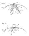
- the means shown in FIG. 11 can be used for this, which can also be used in connection with the application method according to FIGS. 8 and 9.
- the pit edge (51) leading in the direction of rotation of the printing unit cylinder (50) was also covered with a plate (1) which has an area (5).
- no adhesive is used above the trailing edge of the pit (52).
- FIG. 12 A further advantageous variant of the invention results from FIG. 12, in which a plate cylinder (63) is shown, in which the ends of the pressure plate or mold are inserted together in a single narrow cylinder slot (64) which extends in the axial direction.
- Such cylinders can also be covered with an elastic plate, here an elastic plate (65) corresponding to the structure according to FIG.
- the end (66) of the plate (65) leading in the direction of rotation of the cylinder (63) is fixed in the manner already described in connection with FIGS. 7 and 8 with the aid of an insert strip (67) on the one pit wall of the cylinder slot (64).
- the cylinder slot (64) advantageously has a recess (69) on the trailing edge of the pit (52).
- the length of the plate (65) to be glued is now dimensioned such that the trailing plate end (68), as indicated in FIG. 12, only projects as far beyond the trailing edge of the pit (52) as the cylinder slot is wide.
- an elastic pressure roller (70) on the jacket of the plate cylinder (63) corresponding to the pressure roller (39) after the plate (65) has been rolled onto the cylinder jacket, the trailing plate end (68) is now pressed into the recess (69), wherein the deformation of the pressure roller (70) shown in dashed lines in the region (71) can be observed.
- the area in the recess (69) was previously provided with a suitable adhesive or, if necessary, with this arrangement according to FIG. 12, only the very narrow end (68) protruding beyond the trailing edge of the pit can be glued with the film, which, however is somewhat less convenient than using a liquid adhesive or a pressure sensitive adhesive.
- the inventive use of the newly constructed and manufactured flexible plate thus enables a safe, uniform and bubble-free application of a protective coating on printing unit cylinders which adhere with uniform force over the entire cylinder jacket and which, due to the homogeneity of the adhesive, ensure a favorable concentricity of the coated cylinder.
- the advantages that the present invention brings include in the fact that instead of the previously required complex coating of printing unit cylinders with chrome, nickel, ceramic or other corrosion-resistant layers can now be carried out more cheaply, a further advantage being that the subsequent application of the plate according to the invention in the installed state or the replacement of already applied plates is inexpensive to do.
Abstract
Zur Beschichtung bzw. Belegung eines Druckwerkzylinders (30, 44, 50, 63) wird eine flexible Platte (1, 36, 65) verwendet, die entsprechend dem zu belegenden Zylinderumfang mit einer beidseitig klebenden Folie (2) versehen ist. Das nachlaufende Ende (4, 38, 68) der Aufzuklebenden Platte (1, 36, 65) ist mit einem Flüssigkleber versehen. Mittels Fixierleiten (41, 57, 58, 67) wird zunächst das vorauslaufende Ende an einer Wand der Zylindergrube (31, 47, 64) festgelegt, wonach unter Aufwalzung die Platte auf den Mantel geklebt wird und abschließend das hintere Ende unter Verwendung des Flüssig- bzw. druckempfindlichen Klebstoffes an die andere Zylinderwand angeklebt wird. 
Description
Die Erfindung betrifft ein Verfahren zum Aufbringen eines Schutzbelages auf einen Druckwerkzylinder gemäß dem Oberbegriff des Patentanspruchs 1 und Vorrichtungen zur Durchführung des Verfahrens.The invention relates to a method for applying a protective coating to a printing couple cylinder according to the preamble of
Aus der DE-OS 3 401 350 ist es bekannt, Durchwerkzylinder mit einer keramischen Beschichtung zu versehen, die sowohl den Zylindermantel als auch teilweise die Grubenwände der Zylindergrube bedeckt. Es ist außerdem beispielsweise aus der DE-AS 22 49 195 bekannt, dünne als Druckformträger dienende Platten auf einen Druckwerkzylinder aufzukleben, wobei auf einer Grundplatte ein Rahmen verwendet wird, in den die Platte eingeklebt wird. Diese Platten bedecken jedoch nur teilweise die Manteloberfläche der Zylinder, so daß diese durch die Platten nicht vollständig gegen Korrosion geschützt sind.From DE-OS 3 401 350 it is known to provide through-cylinder with a ceramic coating which covers both the cylinder jacket and partially the pit walls of the cylinder pit. It is also known, for example from DE-AS 22 49 195, to glue thin plates serving as printing form carriers to a printing couple cylinder, a frame being used on a base plate into which the plate is glued. However, these plates only partially cover the outer surface of the cylinders, so that the plates do not completely protect them against corrosion.
Aufgabe der Erfindung ist es, ein Verfahren zum Aufbringen eines Schutzbelages auf einen Druckwerkzylinder zu schaffen, der den Zylindermantel und zumindest teilweise die Grubenwände bedeckt, in Form einer biegsamen Platte, die mit einer homogenen Klebstoffschicht mit gleicher Dicke versehen ist und über den gesamten Zylinder mit einer gleichmäßigen Klebekraft blasenfrei aufgebracht wird. Diese Aufgabe wird durch die Merkmale des kennzeichnenden Teils gelöst. Weiterbildungen der Erfindung ergeben sich aus den Unteransprüchen in Verbindung mit der Beschreibung und den Zeichnungen. In diesen zeigen schematisch:
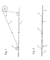
- Fig.1 die Belegung einer flexiblen Platte mit einer Klebstoffolie,
- Fig.2 die erfindungsgemäß beschichtete, flexible Platte,
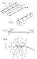
- Fig.3 bis 6 eine Vorrichtung zum kantengenauen Abbiegen der Platte gemäß Fig.2,
- Fig.7 die in Fig.2 dargestellte, an den Enden abgewinkelte, flexible Platte,
- Fig.8 und 9 die erfindungsgemäße Belegung eines Druckwerkzylinders mit einer Platte gemäß Fig.2,
- Fig.10 und 11 die erfindungsgemäße Belegung eines Druckwerkzylinders mit einer Platte gemäß Fig.7 und
- Fig.12 die erfindungsgemäße Belegung eines Plattenzylinders mit einem einzigen schmalen Zylinderschlitz.
- 1 shows the covering of a flexible plate with an adhesive film,
- 2 the flexible plate coated according to the invention,
- 3 to 6 a device for bending the plate with the exact edge according to FIG. 2,
- 7 the flexible plate shown in FIG. 2, angled at the ends,
- 8 and 9 the assignment according to the invention of a printing couple cylinder with a plate according to FIG. 2,
- 10 and 11 the assignment of a printing unit cylinder according to the invention with a plate according to Fig. 7 and
- 12 shows the assignment of a plate cylinder according to the invention with a single narrow cylinder slot.
Gemäß Fig.1 wird eine biegsame Platte (1), die korrosionsbeständig ist, wie beispielsweise Nirosta, mit einer Folie (2) belegt, die auf beiden Seiten eine homogene Klebstoffschicht trägt. Der Klebstoff auf der Folie (2) soll eine sofortige Klebung bewirken, sobald er mit einer Gegenschicht- bzw. -fläche in Kontakt gelangt, wobei es nicht zwingend erforderlich ist, daß sofort die maximale Klebewirkung erreicht wird. Derartige Kleber werden als sogenannte "einseitige Kontaktkleber" bezeichnet. Die Klebstoffschicht auf der Folie (2) muß äußerst homogen sein und eine gleichmäßige Dicke aufweisen. Die Folie (2) bzw. die auf dieser auf beiden Seiten befindlichen Klebstoffschichten werden durch eine Schutzschicht S, beispielsweise ebenfalls aus einem dünnen Folienmaterial, abgedeckt, so daß eine Lagerhaltung der Klebefolie auf einer Wickelrolle möglich ist. In erfindungsgemäßer Weise soll zunächst die in Fig.2 gezeigte Platte (1) mit einer Folie (2) beschichtet werden, wobei die in die Zylindergruben einzuführenden Plattenenden (3, 4) in unterschiedlicher Weise angeklebt werden. Während das Plattenende (3) sowie die übrige, den Zylindermantel bedeckende Platte (1) mit der Folie (2) bedeckt wird, ist das andere Plattenende (4) nicht mit der Folie (2) belegt. Vorzugsweise wird ein folienfreier Bereich bzw. Raum (5) auf der Platte (1) vorgesehen, der, wie später noch im einzelnen erläutert wird, über der vorauslaufenden Grubenkante zu liegen kommt. Gemäß Fig.1 wird die Folie (2) von einer Vorratsrolle (6) abgezogen und mit Hilfe einer elastischen Andruckwalze (7) auf die flexible Platte (1) blasenfrei und mit gleichmäßigem Andruck aufgewalzt. Hierbei ist besondere Sorgfalt anzuwenden, so daß bereits die Folie (2) blasenfrei und mit gleichmäßiger Klebekraft auf der Platte (1) zu liegen kommt. Für die Erzeugung des Berreiches (5) kann nach träglich ein schmaler Streifen herausgeschnitten werden, wenn die Platte (1) mit der Folie (2), mit Ausnahme des Plattenendes (4), belegt ist. Bei der Darstellung gemäß Fig.2 befindet sich somit lediglich noch auf der oberen Seite der Folie (2) eine Schutzfolie S, die die obere Klebeschicht abdeckt.According to FIG. 1, a flexible plate (1) that is corrosion-resistant, such as, for example, stainless steel, is covered with a film (2) that has a homogeneous adhesive layer on both sides. The adhesive on the film (2) is intended to bring about an immediate bond as soon as it comes into contact with a counter layer or surface, it not being absolutely essential that the maximum adhesive effect be achieved immediately. Such adhesives are referred to as so-called "single-sided contact adhesives". The adhesive layer on the film (2) must be extremely homogeneous and have a uniform thickness. The film (2) or the adhesive layers located on this on both sides are covered by a protective layer S, for example also made of a thin film material, so that the adhesive film can be stored on a winding roll. In the manner according to the invention, the plate (1) shown in FIG. 2 is first to be coated with a film (2), the plate ends (3, 4) to be inserted into the cylinder pits being glued in different ways. While the plate end (3) and the remaining plate (1) covering the cylinder jacket are covered with the film (2), the other plate end (4) is not covered with the film (2). A film-free area or space (5) is preferably provided on the plate (1), which, as will be explained in more detail later, comes to lie above the leading edge of the pit. According to FIG. 1, the film (2) is pulled off a supply roll (6) and rolled onto the flexible plate (1) without bubbles and with even pressure using an elastic pressure roller (7). Here is Take special care so that the film (2) comes to lie on the plate (1) without bubbles and with a uniform adhesive force. To create the area (5), a narrow strip can subsequently be cut out if the plate (1) is covered with the film (2), with the exception of the plate end (4). In the illustration according to FIG. 2, there is therefore only a protective film S on the upper side of the film (2) which covers the upper adhesive layer.
In den Figuren 3 bis 6 ist eine Biegevorrichtung dargestellt, mit der die in Fig.2 gezeigte Platte (1) an den beiden Enden (3, 4) abgewinkelt werden kann, um später in erfindungsgemäßer Weise die Enden (3, 4) an den Grubenwänden von Druckwerkzylindern zu befestigen, d.h. zu verkleben. Entsprechend dem Mantelumfang erfolgt eine kantengenaue Abbiegung der Platte (1) mit der in den Figuren 3 bis 6 dargestellten Biegevorrichtung. Diese umfaßt Seitenwände (9, 10), zwischen denen ein Zylinder (11) gelagert ist, der eine relativ breite Grube (12) aufweist. Breite und Durchmesser des als Biegeform dienenden Zylinders (11) sind also auf die Größe des mit der Platte (1) zu belegenden Druckwerkzylinders exakt abgestimmt.FIGS. 3 to 6 show a bending device with which the plate (1) shown in FIG. 2 can be angled at the two ends (3, 4) in order to later use the ends (3, 4) in accordance with the invention To fix pit walls of printing unit cylinders, ie to glue. Corresponding to the circumference of the casing, the plate (1) is bent to the exact edge using the bending device shown in FIGS. 3 to 6. This comprises side walls (9, 10), between which a cylinder (11) is mounted, which has a relatively wide pit (12). The width and diameter of the cylinder (11) serving as the bending shape are therefore precisely matched to the size of the printing unit cylinder to be covered with the plate (1).
In der Grube (12) befindet sich eine Stützleiste (13), parallel und in der Nähe der Grubenwand (14). Der Abstand der Stützleiste (13) zur anderen Grubenwand (15) ist vorzugsweise etwas größer als der Abstand zwischen der Stütztleiste (13) und der Grubenwand (14). Dadurch kann die in Fig.4 dargestellte Einsatzleiste (16), die Löcher (17) aufweist, mit nicht dargestellten Schrauben in im Boden der Grube (12) befindliche Gewindelöcher eineschraubt werden. Zwischen der der Grubenwand (15) zugewandten Seite der Einsatzleiste (16) und der Grubenwand (15) ist eine Zug- und Fixierleiste (22) gemäß Fig.6 und zwischen der Stützleiste (13) und der Grubenwand (14) eine Fixierleiste (19) gemäß Fig.5 einsetzbar. Die Fixierleiste (19) und die Zug- und Fixierleiste (22) weisen durchgehende Löcher (20 bzw.23) sowie Exzenterlöcher (21 bzw. 24) auf. In letztere werden beispielsweise mit einem Imbusschlüssel drehbare, nicht gezeigte Exzenter eingesetzt, die beim Drehen aus den Seitenflächen der Leisten (19, 22) herausdrehbar sind.In the pit (12) there is a support bar (13), parallel and in the vicinity of the pit wall (14). The distance of the support bar (13) to the other pit wall (15) is preferably somewhat larger than the distance between the support bar (13) and the pit wall (14). As a result, the insert strip (16) shown in FIG. 4, which has holes (17), can be screwed into threaded holes in the bottom of the pit (12) using screws, not shown. Between the side of the insert bar (16) and the pit wall (15) facing the pit wall (15) there is a pulling and fixing bar (22) according to FIG. 6 and a fixing bar (19) between the support bar (13) and the pit wall (14) ) can be used according to Fig. 5. The fixing bar (19) and the pulling and fixing bar (22) have through holes (20 and 23 respectively) and eccentric holes (21 and 24). In the latter, eccentrics, not shown, are used, for example, with an Allen key, which can be rotated out of the side faces of the strips (19, 22) during rotation.
Zur kantengenauen Biegung der Platte gemäß Fig.2 wird zunächst das Plattenende (3) in die Grube (12) so eingelegt, daß dieses in Anlage mit der Grubenwand (14) kommt. Anschließend erfolgt die Einfügung der Fixierleiste (19) zwischen Grubenwand (14) und Stützleiste (13), wobei dieses mittels Schrauben am Grubenboden festgelegt und durch drehbare Exzenter in den Exzenterlöchern (21) gegen die Grubenwand (14) bzw. gegen das an der Grubenwand (14) anliegende Ende (3) der Platte (1) angepreßt wird, so daß das Plattenende (3) exakt fixiert ist. Durch manuelles oder motorisches Drehen des Zylinders (11) wird nun durch eine elastische Anpreßrolle (25), die ebenfalls zwischen den Seitenwänden (10, 11) drehbar gelagert ist, eine kantengenaue Abwinklung des in der zuvor beschriebenen Weise festgelegten Endes, hier (3) der Platte (1) erreicht und beim Weiterdrehen des Zylinders (11) die Platte (5) auf den Mantel des Zylinders (11) aufgerollt, bis durch die Anpreßrolle (25) das andere Plattenende, hier (4), abgekantet und in die Grube (12) hineingedrängt wird. Nachdem mit Hilfe der Anpreßrolle (25) die Abkantung exakt abgeschlossen ist, wird das Plattenende (4), beispielsweise mit der Hand, gegen die Grubenwand (15) angelegt und anschließend zwischen die Einsatzleiste (16), die mittels der Löcher (17) und der Gewindelöcher (18) in der Grube (12) bereits befestigt wurde, und die Grubenwand (15) die Zug- und Fixierleiste (22) eingesetzt. Durch drehbare, nicht gezeigte Exzenter in den Exzenterlöchern (24) wird nunmehr vollends das Ende (4) gegen die Grubenwand (25) gepreßt, wonach mit Hilfe der durch die Bohrungen (23) in die Gewindebohrungen (18) eingreifenden Schrauben die Zug- und Fixierleiste (22) unter Andruck an die Grubenwand (15) bzw. an das an dieser aufliegende Plattenende (4) nach unten, d.h. in Richtung Grubenboden, gezogen wird. Dadurch wird der Abkantvorgang abgeschlossen, wobei das Plattenende entlang der Grubenwand (15) nach unten gezogen wird. Vorzugsweise soll zumindest die an dem Plattenende (4) anliegende Seite der Zug- und Fixierleiste (22) aufgerauht, beispielsweise geriffelt sein, so daß die Zugwirkung, die auf das Ende (4) der Platte wirkt, erhöht wird. Ein ähnliche Riffelung bzw. Aufrauhung kann auch an der entsprechenden Seite der Fixierleiste (19) vorgenommen werden.For the edge-precise bending of the plate according to FIG. 2, the plate end (3) is first inserted into the pit (12) so that it comes into contact with the pit wall (14). The fixing bar (19) is then inserted between the pit wall (14) and the support bar (13), this being fixed to the pit floor by means of screws and by means of rotatable eccentrics in the eccentric holes (21) against the pit wall (14) or against that on the pit wall (14) abutting end (3) of the plate (1) is pressed so that the plate end (3) is exactly fixed. By manual or motorized rotation of the cylinder (11), an elastic pinch roller (25), which is also rotatably mounted between the side walls (10, 11), is used to precisely bend the end defined in the manner described above, here (3) reached the plate (1) and, when the cylinder (11) is turned further, the plate (5) is rolled onto the jacket of the cylinder (11) until the other plate end, here (4), is bent over by the pressure roller (25) and into the pit (12) is pushed into it. After using the pressure roller (25) the bend is exactly finished, the plate end (4), for example by hand, is placed against the pit wall (15) and then between the insert bar (16), which is by means of the holes (17) and the threaded holes (18) have already been fastened in the pit (12), and the pit wall (15) has inserted the pulling and fixing strip (22). The end (4) is now pressed completely against the pit wall (25) by means of rotatable eccentrics, not shown, in the eccentric holes (24), after which the pulling and pulling screws are inserted through the holes (23) into the threaded holes (18) Fixing strip (22) is pressed downwards against the pit wall (15) or the plate end (4) resting thereon, ie towards the pit floor. This completes the folding process, with the plate end being pulled down along the pit wall (15). Preferably, at least the side of the pulling and fixing strip (22) abutting the plate end (4) should be roughened, for example corrugated, so that the pulling action which acts on the end (4) of the plate is increased. A similar corrugation or roughening can also be carried out on the corresponding side of the fixing strip (19).
Eine weitere vorteilhafte Ausbildung der Biegevorrichtung gemäß Fig.3 besteht darin, daß der Zylinder (11) Schneidnuten (26, 27) an den beiden Seiten aufweist, in die scheibenförmige Messer (28, 29) eingreifen. Wenn der Biegevorgang abgeschlossen ist, wird durch entsprechende Anstellung der Messer (28, 29) die Platte (1) auf dem Zylinder (11) exakt und verzugsfrei auf die erforderliche Breite zugeschnitten.Another advantageous embodiment of the bending device according to FIG. 3 is that the cylinder (11) has cutting grooves (26, 27) on both sides, into which disk-shaped knives (28, 29) engage. When the bending process is complete, the plate (1) on the cylinder (11) is cut to the required width precisely and without distortion by appropriate adjustment of the knives (28, 29).
Die auf der Vorrichtung gemäß Fig.3 gebogene Platte (2) kann nunmehr durch Lösen der Teile (16, 19, 22) von dem Zylinder (11) abgenommen und wieder in die in Fig.7 dargestellte Lage gebracht werden. In vorteilhafter Weise kann die vorgebogene Platte (1) nachträglich auf einen Zylinder in einer Druckmaschine aufgebracht werden, was im nachfolgenden noch im einzelnen beschrieben wird.The plate (2) bent on the device according to FIG. 3 can now be removed from the cylinder (11) by loosening the parts (16, 19, 22) and brought back into the position shown in FIG. Advantageously, the pre-bent plate (1) can be subsequently applied to a cylinder in a printing press, which will be described in more detail below.
Zunächst wird jedoch unter Bezugnahme auf die Figuren 8 und 9 das erfindungsgemäße Aufbringen einer Platte (36) beschrieben, die den Aufbau gemäß Fig.2 aufweist, wobei keine Vorbiegung bzw. Vorabkantung erforderlich ist. Vorzugsweise wird das in Zusammenhang mit Fig. 8 und 9 beschriebene Verfahren bei der Herstellung eines Druckwerkzylinders angewendet, während das in Fig.10 dargestellte Verfahren sich zum Aufbringen der Platte (1) im eingebauten Zustand der Druckwerkzylinder eignet. Der in den Figuren 8 und 9 dargestellte Zylinder (30), beispielsweise ein Gummituchzylinder, weist eine Grube (31) mit Kanälen (32, 33) auf, an deren Wänden (34, 35) die Plattenenden 37, 38) einer flexiblen Platte (36), die wie die Platte (1) gemäß Fig.2 beschichtet ist, befestigt wird. Das Aufrollen der Platte (36) auf den Zylinder (30) erfolgt unter Verwendung einer Anpreßrolle (39), die drehbar an dem Mantel des Zylinders (30) angestellt ist. Der Zylinder (30) dreht im Druckbetrieb ebenfalls in Richtung des Pfeiles.First of all, however, the application of a plate (36) according to the invention, which has the structure according to FIG. 2, is described with reference to FIGS. 8 and 9, wherein no pre-bending or pre-bending is required. The method described in connection with FIGS. 8 and 9 is preferably used in the production of a printing group cylinder, while the method shown in FIG. 10 is suitable for applying the plate (1) in the installed state of the printing group cylinders. The cylinder (30) shown in FIGS. 8 and 9, for example a blanket cylinder, has a pit (31) with channels (32, 33), on the walls (34, 35) of which the plate ends 37, 38) of a flexible plate ( 36), which is coated like the plate (1) according to FIG. 2. The plate (36) is rolled onto the cylinder (30) using a pressure roller (39) which is rotatably attached to the jacket of the cylinder (30). The cylinder (30) also rotates in the direction of the arrow in printing operation.
Zunächst wird unter Entfernung der unteren Schutzfolie S das mit der Folie (2) belegte Ende (37) der Platte (36) an die Grubenwand (34) angelegt, wonach in den Grubenkanal (32) eine Fixierleiste (40) eingefügt und am Boden des Grubenkanals (32) angeschraubt wird. Die Fixierleiste (40) ist vorzugsweise ähnlich aufgebaut wie die Fixierleiste (19) gemäß Fig.5. Anschließend wird unter Drehung des Zylinders (30) die Platte (36) durch die Anpreßrolle (39) auf den Mantel des Zylinders (30) aufgeklebt, wobei die entsprechende Schutzfolie S sukzessive entfernt werden muß. Dieser Vorgang erfolgt so lange, bis entsprechend der in Fig.8 dargestellten Position die Anpreßrolle (39) das hintere Ende (38) der Platte (36) an der nachlaufenden Grubenkante abkantet und zumindest teilweise das hintere Ende (38) in die Grube (31) hineindrückt. Im hinteren Mantelbereich, etwa bei (42), wird dabei die Schutzfolie S nicht sofort von der Klebstoffschicht entfernt, da nach erfolgter Abkantung des Endes (38) an der nachlaufenden Kante (52) die Rolle (39) oder der Zylinder wieder in entegegengesetzter Richtung gedreht wird, wonach, wie in Fig.8 gestrichelt angedeutet wurde, das Ende (38) in den Grubenkanal (33) hineingesteckt wird. Nunmehr wird über den Bereich (42) mit Hilfe der Anpreßrolle (39) die Platte unter Enfernung der Schutzfolie S endgültig auf den Mantel des Zylinders (30) bis zur nachlaufenden Grubenkante (52) aufgewalzt, d.h. aufgeklebt. Dabei wird die Platte (36) exakt um die nachlaufende Grubenkante (52) gebogen. In dieser Stellung erfolgt die Einfügung einer Zug- und Fixierleiste (41), die entsprechend der Zug- und Fixierleiste (22) gemäß Fig.6 aufgebaut ist. Vor dem Einfügevorgang wurden jedoch entweder die untere Seite des Endes (38) der Platte (36) oder die Grubewand (35) mit einem flüssigen Klebstoff oder einem druckempfindlichen Klebstoff bestrichen, der bei einer Anlage des Endes (38) an die Grubenwand (35) zunächst noch eine Verschiebung des Endes (38) an der Grubenwand (35) zuläßt. Dadurch wird in erfindungsgemäßer Weise erreicht, daß beim Einziehen bzw. Einschrauben der Zug- und Fixierleiste (41) eine exakte Anlage und Streckung der Platte (36) bzw. des Endes (38) entlang der nachlaufenden Grubenkante (52) und der Grubenwand (35) erfolgt. Die Leisten (40, 41) bleiben nun so lange in den Grubenkanälen (32, 33), bis die verwendeten Klebstoffe ihre endgültige Festigkeit in etwa erreicht haben. Wie Fig.8 erkennen läßt, wurde die Platte (36) auch um die vorauslaufende Grubenkante (51) exakt herumgeführt, wobei es äußerst vorteilhaft ist, daß der Bereich oberhalb der vorauslauslaufenden Grubenkante (51), in Drehrichtung des Druckwerkzylinders, frei von der Klebefolie ist (siehe Bereich 5). Dadurch kann keine Materialanhäufung an der Grubenkante (51) bei der Abkantung auftreten, wodurch ansonsten die Lebensdauer der Beschichtung ungünstig beeinflußt würde und eine Abkantung nicht exakt möglich wäre.First, with removal of the lower protective film S, the end (37) of the plate (36) covered with the film (2) is placed against the pit wall (34), after which a fixing strip (40) is inserted into the pit channel (32) and at the bottom of the Pit channel (32) is screwed. The fixing bar (40) is preferably constructed similarly like the fixing bar (19) according to Fig. 5. Then, while rotating the cylinder (30), the plate (36) is glued onto the jacket of the cylinder (30) by the pressure roller (39), the corresponding protective film S having to be removed successively. This process continues until, according to the position shown in FIG. 8, the pressure roller (39) folds the rear end (38) of the plate (36) at the trailing edge of the pit and at least partially the rear end (38) into the pit (31 ) pushes in. In the rear cladding area, for example at (42), the protective film S is not immediately removed from the adhesive layer, since after the end (38) has been bent, the roller (39) or the cylinder on the trailing edge (52) again in the opposite direction is rotated, after which, as indicated by the broken line in FIG. 8, the end (38) is inserted into the pit channel (33). Now the plate (42) is finally rolled onto the jacket of the cylinder (30) to the trailing edge of the pit (52) with the help of the pressure roller (39), removing the protective film S, ie glued on. The plate (36) is bent exactly around the trailing edge of the pit (52). In this position, a pulling and fixing strip (41) is inserted, which is constructed in accordance with the pulling and fixing strip (22) according to FIG. Before the insertion process, however, either the lower side of the end (38) of the plate (36) or the pit wall (35) was coated with a liquid adhesive or a pressure-sensitive adhesive which, when the end (38) was in contact with the pit wall (35) initially allows a displacement of the end (38) on the pit wall (35). It is thereby achieved in the manner according to the invention that when the pulling and fixing strip (41) is pulled in or screwed in, the plate (36) or the end (38) lies precisely and extends along the trailing edge of the pit (52) and the pit wall (35 ) he follows. The strips (40, 41) now remain in the pit channels (32, 33) until the adhesives used have approximately reached their final strength. As can be seen in FIG. 8, the plate (36) was also guided exactly around the leading pit edge (51), it being extremely advantageous that the area above the leading pit edge (51), in the direction of rotation of the printing unit cylinder, was free of the adhesive film is (see area 5). As a result, no material accumulation on the Pit edge (51) occur during the fold, which would otherwise have an adverse effect on the life of the coating and a fold would not be possible exactly.
In Fig.10 sind schematisch Gummizylinder (43, 44) mit zugeordneten Plattenzylindern (45, 46) angedeutet, wie sie in herkömmlichen Rollenrotationsdruckmaschinen verwendet werden. Hier soll nachträglich oder bei erforderlicher Auswechslung des Schutzbelages das Aufbringen einer flexiblen Platte bei eingebautem Druckwerkszylinder, hier eines Gummituchzylinders (44), demonstriert werden. Dazu wird die gemäß Fig.7 abgewinkelte Platte (1) mit dem mit Folie (2) bedeckten Ende (3) in die Grube eingelegt und in der bereits in Zusammenhang mit den Figuren 8 und 3 beschriebenen Weise mittels eines Fixierstüches bzw. Fixierleiste fixiert. Anschließend weren die beiden Gummizylinder langsam gedreht und zwischen den Gummituchzylindern (43, 44) eine deformierbare, also elatische Anpreßrolle (48) angesetzt. Dadurch wird im Deformierbereich (49) die Anpreßrolle (48) zwischen die Gummituchzylinder (43) und (44) gezogen, so daß beim Drehen der Zylinder (43, 44) die Platte (1) mit großer und gleichmäßiger Anpreßkraft auf den Mantel des Zylinders (44) bei vorheriger Entfernung der unteren Schutzfolie S aufgeklebt wird. Die Anpreßrolle dreht nur mit niedriger Drehzahl, da sie durch den Gummizylinder (43) getrennt wird. Wenn der Gummituchzylinder (44) mit der Grube (47) in die gestrichelt dargestellte Position gelangt, so kann das nicht mit Folie beschichtete Ende (4) ebenfalls in die Grube eingefügt werden. Hierfür können die in Fig.11 dargestellten Mittel verwendet werden, die auch im Zusammenhang mit dem Aufbringverfahren gemäß den Figuren 8 und 9 verwendbar sind.10 schematically shows rubber cylinders (43, 44) with associated plate cylinders (45, 46), as are used in conventional web-fed rotary printing presses. Here, the application of a flexible plate with a built-in printing unit cylinder, here a blanket cylinder (44), is to be demonstrated retrospectively or if the protective covering needs to be replaced. For this purpose, the plate (1) angled according to FIG. 7 is inserted into the pit with the end (3) covered with film (2) and fixed in the manner already described in connection with FIGS. 8 and 3 by means of a fixing piece or fixing strip. Then the two rubber cylinders are slowly rotated and a deformable, thus elastic pressure roller (48) is placed between the rubber blanket cylinders (43, 44). As a result, the pressure roller (48) is pulled between the blanket cylinders (43) and (44) in the deforming area (49), so that when the cylinders (43, 44) are rotated, the plate (1) is pressed onto the jacket of the cylinder with a large and uniform pressure force (44) if the lower protective film S is removed beforehand. The pressure roller only rotates at low speed because it is separated by the rubber cylinder (43). When the blanket cylinder (44) with the pit (47) reaches the position shown in dashed lines, the end (4) not coated with film can also be inserted into the pit. The means shown in FIG. 11 can be used for this, which can also be used in connection with the application method according to FIGS. 8 and 9.
Der in Fig.11 dargestellte Zylinder (50), beispielsweise ein Gummituchzylinder, wurde mit einer Platte (1) gemäß Fig.2 oder 7 belegt. Die in Drehrichtung des Druckwerkzylinders (50) gesehen vorauslaufende Grubenkante (51) wurde ebenfalls mit einer Platte (1) belegt, die einen Bereich (5) aufweist. Vorzugsweise wird auch oberhalb der nachlaufenden Grubenkante (52) kein Klebstoff verwendet.The cylinder (50) shown in FIG. 11, for example a blanket cylinder, was covered with a plate (1) according to FIG. 2 or 7. The pit edge (51) leading in the direction of rotation of the printing unit cylinder (50) was also covered with a plate (1) which has an area (5). Preferably, no adhesive is used above the trailing edge of the pit (52).
Die Enden (3, 4) die in der bereits beschriebenen Weise an den Grubenwänden (53, 54) gefestigt wurden, wofür die mittels Gewindelöchern (55, 56) befestigbaren Fixierleisten (57, 58) verwendet wurden, entsprechend den Leisten (19, 22, Fig.5, 5). Dadurch werden die Plattenenden (59, 60) gegen die Grubenwände (53, 54) gepreßt, wobei in der beschriebenen Weise auf das Plattenende (60) eine Zugwirkung in Richtung Grubenboden ausgeübt wurde. Die Grubenkanäle sind mit den Gewindelöchern (55, 56) versehen, in die nicht nächer bezeichnete Schrauben, die durch Löcher (61, 62) in den Leisten (57, 58) geführt werden, eingreifen. Nach entsprechender Trocknung der verwendeten Klebstoffe werden die Teile (57, 58) wieder entfernt, wonach der Vorgang abgeschlossen ist.The ends (3, 4) which were fastened to the pit walls (53, 54) in the manner already described, for which purpose the fixing strips (57, 58) which could be fastened by means of threaded holes (55, 56) were used, corresponding to the strips (19, 22 , Fig. 5, 5). As a result, the plate ends (59, 60) are pressed against the pit walls (53, 54), a pulling action being exerted on the plate end (60) in the direction of the pit floor in the manner described. The pit channels are provided with the threaded holes (55, 56) which are engaged by screws, not specified, which are guided through holes (61, 62) in the strips (57, 58). After appropriate drying of the adhesives used, the parts (57, 58) are removed again, after which the process is completed.
Eine weitere vorteilhafte Variante der Erfindung ergibt sich aus Fig.12, in der ein Plattenzylinder (63) dargestellt ist, bei dem die Druckplatte bzw. Form mit ihren Enden gemeinsam in einem einzigen schmalen, sich in Achsrichtung erstreckenden Zylinderschlitz (64) eingefügt werden. Auch derartige Zylinder können nach dem erfindungsgemäßen Verfahren mit einer elastischen Platte, hier einer elastischen Platte (65) entsprechend dem Aufbau gemäß Fig.2, belegt werden. Das in Drehrichtung des Zylinders (63) vorauslaufende Ende (66) der Platte (65) wird in der bereits in Zusammenhang mit den Figuren 7 und 8 beschriebenen Weise mit Hilfe einer Einsatzleiste (67) an der einen Grubenwand des Zylinderschlitzes (64) festgelegt. In vorteilhafter Weise weist der Zylinderschlitz (64) an der nachlaufenden Grubenkante (52) eine Ausnehmung (69) auf. Die Länge der aufzuklebenden Platte (65) ist nun so bemessen, daß das nachlaufende Plattenende (68), wie in Fig.12 angedeutet, nur so weit über die nachlaufende Grubenkante (52) hinausragt, wie der Zylinderschlitz breit ist. Durch die Verwendung einer elastischen Anpreßrolle (70) am Mantel des Plattenzylinders (63) entsprechend der Anpreßrolle (39) wird nach dem erfolgten Aufwalzen der Platte (65) auf dem Zylindermantel nunmehr das nachlaufende Plattenende (68) in dei Ausnehmung (69) hineingepreßt, wobei die gestrichelt dargestellte Deformierung der Anpreßrolle (70) im Bereich (71) zu beobachten ist. Selbstverständlich wurde vorher der Bereich in der Ausnehmung (69) mit einem entsprechenden Klebstoff versehen oder ggf. kann bei dieser Anordnung gemäß Fig.12 auch das nur sehr schmale, über die nachlaufende Grubenkante hinausragende Ende (68) mit der Folie beklebt sein, was jedoch etwas ungünstiger ist als die Verwendung eines Flüssigklebers oder eines druckempfindlichen Klebers.A further advantageous variant of the invention results from FIG. 12, in which a plate cylinder (63) is shown, in which the ends of the pressure plate or mold are inserted together in a single narrow cylinder slot (64) which extends in the axial direction. Such cylinders can also be covered with an elastic plate, here an elastic plate (65) corresponding to the structure according to FIG. The end (66) of the plate (65) leading in the direction of rotation of the cylinder (63) is fixed in the manner already described in connection with FIGS. 7 and 8 with the aid of an insert strip (67) on the one pit wall of the cylinder slot (64). The cylinder slot (64) advantageously has a recess (69) on the trailing edge of the pit (52). The length of the plate (65) to be glued is now dimensioned such that the trailing plate end (68), as indicated in FIG. 12, only projects as far beyond the trailing edge of the pit (52) as the cylinder slot is wide. By using an elastic pressure roller (70) on the jacket of the plate cylinder (63) corresponding to the pressure roller (39), after the plate (65) has been rolled onto the cylinder jacket, the trailing plate end (68) is now pressed into the recess (69), wherein the deformation of the pressure roller (70) shown in dashed lines in the region (71) can be observed. Of course, the area in the recess (69) was previously provided with a suitable adhesive or, if necessary, with this arrangement according to FIG. 12, only the very narrow end (68) protruding beyond the trailing edge of the pit can be glued with the film, which, however is somewhat less convenient than using a liquid adhesive or a pressure sensitive adhesive.
Die erfindungsgemäße Verwendung der neuartig aufgebauten und hergestellten flexiblen Platte ermöglicht also eine sichere, gleichmäßige und blasenfreie Aufbringung eines Schutzbelages auf Druckwerkzylindern, die mit gleichmäßiger Kraft über den gesamten Zylindermantel haften und die infolge der Homogenität des Klebstoffs einen günstigen Rundlauf des beschichteten Zylinders gewährleisten. Der Vorteil, den die vorliegende Erfindung bringt, besteht u.a. darin, daß anstelle der bisher erforderlichen aufwendigen Beschichtung von Druckwerkzylindern mit Chrom, Nickel, Keramik oder anderen korrosionsbeständigen Schichten nunmehr preisgünstiger durchgeführt werden kann, wobei ein weiterer Vorteil darin liegt, daß auch das nachträgliche Aufbringen der erfindungsgemäßen Platte im eingebauten Zustand bzw. das Auswechseln von bereits aufgebrachten Platten kostengünstig zu bewerkstelligen ist.The inventive use of the newly constructed and manufactured flexible plate thus enables a safe, uniform and bubble-free application of a protective coating on printing unit cylinders which adhere with uniform force over the entire cylinder jacket and which, due to the homogeneity of the adhesive, ensure a favorable concentricity of the coated cylinder. The advantages that the present invention brings include in the fact that instead of the previously required complex coating of printing unit cylinders with chrome, nickel, ceramic or other corrosion-resistant layers can now be carried out more cheaply, a further advantage being that the subsequent application of the plate according to the invention in the installed state or the replacement of already applied plates is inexpensive to do.
Claims (10)
dadurch gekennzeichnet,
daß der aus einer flexiblen Platte (1, 36, 65) bestehende Schutzbelag auf einer Seite mit einer beidseitig mit Kontaktklebstoff versehenen Folie (2) belegt wird, in der Weise, daß in Drehrichtung des Druckwerkzylinders (30, 44 50, 63) gesehen, das vorauslaufende in die Grube (31, 47, 64) ragende Plattenende (3, 38, 69) und die auf dem Zylindermantel aufliegende Platte (1, 36, 65) mit der Folie (2) belegt ist, und daß das nachlaufende Ende (4, 38, 68) über der nachlaufenden Zylinderkante (52) und die nachlaufende Grubenwand (35, 54, 69) mit einem Flüssigkleber oder einem druckempfindlichen Kleber befestigt wird.1. Method for applying a protective covering to a printing couple cylinder, which covers the cylinder jacket and, at least partially, the pit walls of the cylinder pit,
characterized,
that the protective covering consisting of a flexible plate (1, 36, 65) is covered on one side with a film (2) provided with contact adhesive on both sides, in such a way that seen in the direction of rotation of the printing unit cylinder (30, 44 50, 63), the leading plate end (3, 38, 69) protruding into the pit (31, 47, 64) and the plate (1, 36, 65) resting on the cylinder jacket are covered with the film (2), and the trailing end ( 4, 38, 68) over the trailing cylinder edge (52) and the trailing pit wall (35, 54, 69) with a liquid adhesive or a pressure sensitive adhesive.
Applications Claiming Priority (2)
| Application Number | Priority Date | Filing Date | Title |
|---|---|---|---|
| DE19853539586 DE3539586A1 (en) | 1985-11-08 | 1985-11-08 | METHOD FOR APPLYING A PROTECTIVE COATING TO A PRINTING CYLINDER WITH DEVICES FOR CARRYING OUT THE METHOD |
| DE3539586 | 1985-11-08 |
Publications (2)
| Publication Number | Publication Date |
|---|---|
| EP0221322A2 true EP0221322A2 (en) | 1987-05-13 |
| EP0221322A3 EP0221322A3 (en) | 1989-03-08 |
Family
ID=6285433
Family Applications (1)
| Application Number | Title | Priority Date | Filing Date |
|---|---|---|---|
| EP86113160A Ceased EP0221322A3 (en) | 1985-11-08 | 1986-09-24 | Process for applying a protective covering to a printing cylinder, and device for carrying out the process |
Country Status (4)
| Country | Link |
|---|---|
| US (1) | US4766811A (en) |
| EP (1) | EP0221322A3 (en) |
| JP (1) | JPS62111745A (en) |
| DE (1) | DE3539586A1 (en) |
Cited By (2)
| Publication number | Priority date | Publication date | Assignee | Title |
|---|---|---|---|---|
| EP1138485A2 (en) * | 2000-03-29 | 2001-10-04 | Koenig & Bauer Aktiengesellschaft | Method and device for secure registration mounting a printing plate on the plate cylinder of a sheet-fed printing machine |
| EP1852258A1 (en) * | 2006-05-02 | 2007-11-07 | Komori Corporation | Processing device |
Families Citing this family (17)
| Publication number | Priority date | Publication date | Assignee | Title |
|---|---|---|---|---|
| US5107763A (en) * | 1990-04-24 | 1992-04-28 | Rockwell International Corporation | Narrow gap plate mounting apparatus and method |
| US5195434A (en) * | 1990-10-02 | 1993-03-23 | M & R Printing Equipment, Inc. | Transfer printing press |
| US5366784A (en) * | 1991-02-26 | 1994-11-22 | Herbison Paul R | Corrosion inhibiting offset printing blanket |
| JPH04284251A (en) * | 1991-03-14 | 1992-10-08 | Toray Ind Inc | Mounting method of form plate of photosensitive resin letterpress |
| US5511476A (en) * | 1993-10-26 | 1996-04-30 | R. R. Donnelley & Sons Co. | Magnetic cylinder with surface gripping |
| US5410963A (en) * | 1994-05-03 | 1995-05-02 | Squarmount, Inc. | Backing blanket for printing plates |
| DE69703783T2 (en) * | 1996-10-28 | 2001-04-19 | Hans E Ruprecht Holding Ag Kra | Device on a printing machine for perforating, punching, cutting, creasing and partial painting or for printing envelopes |
| US5870955A (en) * | 1997-03-05 | 1999-02-16 | Presstek, Inc. | Lithographic printing system with reusable support surfaces and lithographic constructions for use therewith |
| DE59804063D1 (en) * | 1997-06-03 | 2002-06-13 | Koenig & Bauer Ag | ROLLER WITH A RUBBER COVER |
| US6176182B1 (en) * | 1997-08-12 | 2001-01-23 | Fuji Photo Film Co., Ltd. | Block copy material for lithographic printing plate material, lithographic press and lithographic printing method |
| US5947028A (en) * | 1998-05-07 | 1999-09-07 | Creo Products Inc. | Method and apparatus for holding a printing plate on a vacuum drum |
| US6422548B1 (en) | 2000-08-14 | 2002-07-23 | M&R Printing Equipment, Inc. | Adjustable zoned vacuum bed |
| WO2004033224A1 (en) * | 2002-10-11 | 2004-04-22 | Day International, Inc. | Printing blanket and method for reducing corrosion and abrasion of printing blankets and blanket cylinders |
| DE102004051262A1 (en) * | 2004-10-21 | 2006-04-27 | Man Roland Druckmaschinen Ag | Offset printing machine for printing wall paper, has picturization mechanism picturizing re-recordable and erasable offset printing form that has smooth surface, where entire surface of form has defined roughness aligned to offset printing |
| EP2694291B1 (en) | 2011-05-11 | 2021-10-20 | HP Indigo B.V. | Embossing with printed relief pattern |
| US9056520B2 (en) * | 2012-01-31 | 2015-06-16 | Hewlett-Packard Indigo B.V. | Embossing apparatus |
| US10960688B2 (en) | 2015-08-31 | 2021-03-30 | Novus Printing Equipment, Llc | Printer vacuum control system |
Citations (5)
| Publication number | Priority date | Publication date | Assignee | Title |
|---|---|---|---|---|
| US3347162A (en) * | 1964-12-21 | 1967-10-17 | Braco Engraving Company | Printing plates |
| CH477977A (en) * | 1967-11-16 | 1969-09-15 | Albert Schnellpressen | Device for tensioning the elevator on printing machines |
| US3828672A (en) * | 1972-10-17 | 1974-08-13 | American Bank Note Co | Apparatus for fitting flexible printing plates and rigging to printing press cylinders |
| US4092925A (en) * | 1976-08-05 | 1978-06-06 | Fromson H A | Lithographic printing plate system |
| EP0149036A2 (en) * | 1984-01-17 | 1985-07-24 | M.A.N.-ROLAND Druckmaschinen Aktiengesellschaft | Blanket cylinder for rotative offset printing machine |
Family Cites Families (11)
| Publication number | Priority date | Publication date | Assignee | Title |
|---|---|---|---|---|
| US2977876A (en) * | 1958-11-03 | 1961-04-04 | Robert R Myers | Printing plate construction |
| US3353481A (en) * | 1962-06-08 | 1967-11-21 | Potter Instrument Co Inc | High speed printer drum with print plate mounting means |
| US3696745A (en) * | 1971-01-22 | 1972-10-10 | Jay Morton | Composite offset printing plate |
| US3857745A (en) * | 1972-04-18 | 1974-12-31 | Fisher & Paykel | Method of covering articles with leather |
| JPS49129541A (en) * | 1973-04-11 | 1974-12-11 | ||
| US4537129A (en) * | 1980-07-25 | 1985-08-27 | W. R. Grace & Co. | Offset printing blanket |
| DE3341924A1 (en) * | 1983-11-19 | 1985-05-30 | Heidelberger Druckmasch Ag | BENDING DEVICE FOR OFFSET PRINTING PLATES |
| DE3434670A1 (en) * | 1984-09-21 | 1986-04-03 | Basf Ag, 6700 Ludwigshafen | DEVICE FOR COVERING A FORM CYLINDER WITH A WRAPPING PLATE |
| DE3434672C2 (en) * | 1984-09-21 | 1986-09-11 | Fa. Carl Freudenberg, 6940 Weinheim | Process for the production of flexible printed circuit boards for high bending stress |
| DE3536174C1 (en) * | 1985-10-10 | 1986-07-31 | Grünzweig + Hartmann und Glasfaser AG, 6700 Ludwigshafen | Method and device for laminating a pipe insulation shell with a film |
| JPH0673850A (en) * | 1992-08-24 | 1994-03-15 | Matsushita Electric Works Ltd | Lighting window device |
-
1985
- 1985-11-08 DE DE19853539586 patent/DE3539586A1/en active Granted
-
1986
- 1986-09-24 EP EP86113160A patent/EP0221322A3/en not_active Ceased
- 1986-10-30 US US06/925,813 patent/US4766811A/en not_active Expired - Fee Related
- 1986-11-07 JP JP61264148A patent/JPS62111745A/en active Pending
Patent Citations (5)
| Publication number | Priority date | Publication date | Assignee | Title |
|---|---|---|---|---|
| US3347162A (en) * | 1964-12-21 | 1967-10-17 | Braco Engraving Company | Printing plates |
| CH477977A (en) * | 1967-11-16 | 1969-09-15 | Albert Schnellpressen | Device for tensioning the elevator on printing machines |
| US3828672A (en) * | 1972-10-17 | 1974-08-13 | American Bank Note Co | Apparatus for fitting flexible printing plates and rigging to printing press cylinders |
| US4092925A (en) * | 1976-08-05 | 1978-06-06 | Fromson H A | Lithographic printing plate system |
| EP0149036A2 (en) * | 1984-01-17 | 1985-07-24 | M.A.N.-ROLAND Druckmaschinen Aktiengesellschaft | Blanket cylinder for rotative offset printing machine |
Cited By (3)
| Publication number | Priority date | Publication date | Assignee | Title |
|---|---|---|---|---|
| EP1138485A2 (en) * | 2000-03-29 | 2001-10-04 | Koenig & Bauer Aktiengesellschaft | Method and device for secure registration mounting a printing plate on the plate cylinder of a sheet-fed printing machine |
| EP1138485A3 (en) * | 2000-03-29 | 2003-08-20 | Koenig & Bauer Aktiengesellschaft | Method and device for secure registration mounting a printing plate on the plate cylinder of a sheet-fed printing machine |
| EP1852258A1 (en) * | 2006-05-02 | 2007-11-07 | Komori Corporation | Processing device |
Also Published As
| Publication number | Publication date |
|---|---|
| DE3539586A1 (en) | 1987-05-14 |
| JPS62111745A (en) | 1987-05-22 |
| EP0221322A3 (en) | 1989-03-08 |
| DE3539586C2 (en) | 1987-09-17 |
| US4766811A (en) | 1988-08-30 |
Similar Documents
| Publication | Publication Date | Title |
|---|---|---|
| EP0221322A2 (en) | Process for applying a protective covering to a printing cylinder, and device for carrying out the process | |
| DE2948877C2 (en) | Double drum winding machine | |
| EP0554542B1 (en) | Offset printing element | |
| DE4217793C1 (en) | Offset blanket and process for its manufacture | |
| DE4335140C1 (en) | Device for attaching a flexible printing plate | |
| EP1155837B1 (en) | Printing machine with a plate cylinder carrying a plurality of plates | |
| DE4323750A1 (en) | Offset printing forme and method for producing such an offset printing forme | |
| EP1309445B1 (en) | Method for positioning a male mould on a counter-pressure cylinder of an embossing station | |
| DE2829862A1 (en) | DEVICE FOR PUNCHING OR GROOVING AND METHOD OF MANUFACTURING THE SAME | |
| DE4139586C2 (en) | Method and device for forming and detecting a start of the path of a replacement winding roll | |
| EP1093915B1 (en) | Printing blanket with notches for registering and method for aligning the printing blanket | |
| EP0518053B1 (en) | Method and apparatus for producing printed corrugated cardboard in large working widths | |
| DE2948744C2 (en) | Device for attaching format plates for exact format transfer of adhesive applications to format rollers | |
| DD248546A5 (en) | METHOD AND DEVICE FOR FIXING PRESSURE PLATES ON THE PLATE CYLINDER OF A ROLL PRINTING MACHINE FOR STITCH PRINTING | |
| EP0170956A2 (en) | Process for attaching flexible printing plates to the forme cylinder of a printing machine | |
| DE10200440B4 (en) | A method of winding a sheet coated with a pressure-sensitive adhesive | |
| DE3439374C2 (en) | Process for the production of corrugated cardboard and corrugated cardboard machine for carrying out the process | |
| DE4315261C2 (en) | Method and device for producing a honeycomb body | |
| DE2941277C2 (en) | Method for producing a laminate from flexible decorative material and a carrier material web | |
| DE2429693C2 (en) | Covering for a backing roll and method for its manufacture | |
| DE4441447C1 (en) | Method of attaching replacement roll for printer, with automatic flying reel change | |
| WO1998006582A1 (en) | Adhesive tape feeding device for a pressure cylinder | |
| DE20317826U1 (en) | Spiral web of paper is rolled into a tube to form a cylindrical core with an external embossed longitudinal detent | |
| DE4220792A1 (en) | Gluing mechanism using double sided adhesive tape - has roller moved towards material to be glued and parting tape off | |
| AT394974B (en) | METHOD AND DEVICE FOR PRODUCING A COVER, BOOKLED OR THE LIKE. |
Legal Events
| Date | Code | Title | Description |
|---|---|---|---|
| PUAI | Public reference made under article 153(3) epc to a published international application that has entered the european phase |
Free format text: ORIGINAL CODE: 0009012 |
|
| AK | Designated contracting states |
Kind code of ref document: A2 Designated state(s): CH DE FR GB IT LI SE |
|
| PUAL | Search report despatched |
Free format text: ORIGINAL CODE: 0009013 |
|
| AK | Designated contracting states |
Kind code of ref document: A3 Designated state(s): CH DE FR GB IT LI SE |
|
| 17P | Request for examination filed |
Effective date: 19890202 |
|
| 17Q | First examination report despatched |
Effective date: 19900817 |
|
| STAA | Information on the status of an ep patent application or granted ep patent |
Free format text: STATUS: THE APPLICATION HAS BEEN REFUSED |
|
| 18R | Application refused |
Effective date: 19910222 |
|
| RIN1 | Information on inventor provided before grant (corrected) |
Inventor name: LINSKA, RUDOLF |