EP0206332A2 - Apparatus for generating high pressure by underwater shock wave - Google Patents
Apparatus for generating high pressure by underwater shock wave Download PDFInfo
- Publication number
- EP0206332A2 EP0206332A2 EP86108672A EP86108672A EP0206332A2 EP 0206332 A2 EP0206332 A2 EP 0206332A2 EP 86108672 A EP86108672 A EP 86108672A EP 86108672 A EP86108672 A EP 86108672A EP 0206332 A2 EP0206332 A2 EP 0206332A2
- Authority
- EP
- European Patent Office
- Prior art keywords
- shock wave
- high pressure
- ellipsoid
- pseudo
- focus
- Prior art date
- Legal status (The legal status is an assumption and is not a legal conclusion. Google has not performed a legal analysis and makes no representation as to the accuracy of the status listed.)
- Withdrawn
Links
Images
Classifications
-
- G—PHYSICS
- G10—MUSICAL INSTRUMENTS; ACOUSTICS
- G10K—SOUND-PRODUCING DEVICES; METHODS OR DEVICES FOR PROTECTING AGAINST, OR FOR DAMPING, NOISE OR OTHER ACOUSTIC WAVES IN GENERAL; ACOUSTICS NOT OTHERWISE PROVIDED FOR
- G10K15/00—Acoustics not otherwise provided for
- G10K15/04—Sound-producing devices
- G10K15/046—Sound-producing devices using optical excitation, e.g. laser bundle
-
- A—HUMAN NECESSITIES
- A61—MEDICAL OR VETERINARY SCIENCE; HYGIENE
- A61B—DIAGNOSIS; SURGERY; IDENTIFICATION
- A61B17/00—Surgical instruments, devices or methods, e.g. tourniquets
- A61B17/22—Implements for squeezing-off ulcers or the like on the inside of inner organs of the body; Implements for scraping-out cavities of body organs, e.g. bones; Calculus removers; Calculus smashing apparatus; Apparatus for removing obstructions in blood vessels, not otherwise provided for
- A61B17/22004—Implements for squeezing-off ulcers or the like on the inside of inner organs of the body; Implements for scraping-out cavities of body organs, e.g. bones; Calculus removers; Calculus smashing apparatus; Apparatus for removing obstructions in blood vessels, not otherwise provided for using mechanical vibrations, e.g. ultrasonic shock waves
Definitions
- This invention relates to an apparatus for generating such a high pressure caused by underwater shock wave that is applied to a calculus or calculi in a human body or to other desired object.
- the foregoing conventional apparatus is defective in that, in the case of use of the spark discharge, there is a danger of leaking out a high voltage electric current through the liquid to the human body and, in the case of use of the microexplosion of the microexplosive, there is liable to take place a chemical reaction of the explosive with an object to be applied with the high pressure or the liquid is feared to be contaminated with the explosive.
- a purpose of this invention is to provide an apparatus free from the foregoing defects.
- the shock wave generation source comprises a laser means, an optical fiber member and a focusing lens for focusing a laser beam on the foregoing focus position.
- numeral 1 denotes a shock wave generation chamber of which an inner surface is formed into a shape of a part of a pseudo-ellipsoid of rotation
- numeral2 denotes a first focus position of the pseudo-ellipsoid of rotation in the chamber
- numeral 3 denotes a focusing lens for focusing a laser beam outputted from one end of an optical fiber member 4 on the first focus position
- numeral 5 denotes a laser means such as a ruby laser with a Q switch or a Y A G laser with a Q switch connected to the other end of the optical fiber member 4.
- the shock wave generation chamber 1 is so attached to the liquid tank 6 that an opening portion thereof may be in communication with an opening portion made in a side wall of the liquid tank 6 for dipping a human body.
- a water flow jet for removing or sweeping bubbles adhered to an inner surface of the shock wave generation chamber 1 in such a manner that one end thereof may direct toward and along the inner surface of the chamber 1 and the other end thereof is connected to a liquid tank not shown in order that the bubbles adhered to the inner surface of the chamber may be removed or swept by a jet stream of the liquid jetted from the water flow jet 8, lest the shock wave should be interfered with the bubbles.
- a human body is placed in the liquid tank 6 and is so set in position that a part including a calculus in the human body may be coincided with the second focus position of the pseudo-ellipsoid of rotation.
- two laser means 5, 5 are actuated in sequence or simultaneously and a laser beam in a pulse form from each laser means 5 is focused on the foregoing first position 2 through the optical fiber member 4 and the focusing lens 3.
- shock wave there is generated shock wave by strong energy of the laser beam at the first focus position 2, and this shock wave is reflected at the inner surface of the shock wave generation chamber 1.
- This underwater shock wave unlike a sound wave, when reflected, displays a non-linear type reflection form so called "Mach reflection", and thus it is reflected at a reflection angle which is not equal to the incident angle.
- the reflected shock wave is focused sharply on the second focus position 9 in the liquid tank 6. Consequently, there is generated a high pressure in sequence or simultaneously at the second focus position 9, so that the calculus is disintegrated.
- the shock wave generation sources each comprising the laser means 5, the optical fiber member 4 and the focusing lens 3.
- the number of the shock wave generation source is not limited to two, but any desired number thereof is used optionally.
- This invention high pressure generation apparatus may be used for various applications. For instance, besides the above application for disintegration of calculus in the human body, it is applicable to a coating apparatus as shown in Fig. 2(A). Namely, a coating material 11 provided in a recessed portion of a micropiece 10 is set to be coincided with the second focus position 9.
- any metal and any chemicals which are susceptible to a thermal influence and are liable to undergo a chemical change are mixed and a mixture thereof is placedat the second focus position and is applied with a high pressure caused by the shock wave, so that a new substance can be created.
- a shock wave generation source comprises a laser means, an optical fiber member and a focusing lens for focusing a laser beam on the first focusing position of a pseudo-ellipsoid of rotation in a shock wave generation chamber, so that there is no danger of electric shock and it can be avoided that the object to be applied with a high pressure is chemically reacted with the microexplosive and that the liquid in the tank for transmitting the shock wave is contaminated with the microexplosive as occurred in the conventional apparatus.
Abstract
Description
- This invention relates to an apparatus for generating such a high pressure caused by underwater shock wave that is applied to a calculus or calculi in a human body or to other desired object.
- Hitherto, as for the apparatus of this kind, there has been known, for instance, such a type one that is provided with a shock wave generation chamber of which an inner surface is formed into a shape of a part of a pseudo-ellipsoid of rotation and such a liquid tank for dipping a human body that is in communication with an opening portion of the shock wave generation chamber and contains a second focus of the pseudo-ellipsoid of rotation therein so that a spark discharge or a microexplosion of a microexplosive may be effected at a position coincided with the first focus of the pseudo-ellipsoid of rotation and by this shock wave a high pressure may be generated and applied to such a calculus in a human body dipped in the liquid tank that is set in position at the second focus of the pseudeo-ellipsoid of rotation in the liquid so as to disintegrate the calculus.
- The foregoing conventional apparatus is defective in that, in the case of use of the spark discharge, there is a danger of leaking out a high voltage electric current through the liquid to the human body and, in the case of use of the microexplosion of the microexplosive, there is liable to take place a chemical reaction of the explosive with an object to be applied with the high pressure or the liquid is feared to be contaminated with the explosive.
- A purpose of this invention is to provide an apparatus free from the foregoing defects.
- According to this invention, in such a type of apparatus that it is provided with a shock wave generation chamber of which an inner surface is formed into a shape of a part of a pseudo-ellipsoid of rotation and which is to be filled with liquid and a shockwave generation source for generating shock wave at a first focus of the pseudo-ellipsoid so that a high pressure may be applied by the shock wave to an object set in position at a second focus of the pseudo-ellipsoid of rotation, it is characterized in that the shock wave generation source comprises a laser means, an optical fiber member and a focusing lens for focusing a laser beam on the foregoing focus position.
- Now, embodying examples of this invention will be explained with reference to the accompanying drawing as follows:
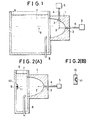
- Fig. 1 is a sectional view of one embodying example of this invention applied to a disintegration apparatus for disintegrating a calculus contained in a human body,
- Fig. 2(A) is a sectional view of another embodying example of this invention applied to a coating apparatus,
- Fig. 2(B) is a sectional view of a micropiece applied with a coating material.
- Fig. 1 shows a sectional view of one example of this invention adapted for a calculus disintegration apparatus for disintegrating calculus or calculi in a human body.
- Referring to Fig. 1,
numeral 1 denotes a shock wave generation chamber of which an inner surface is formed into a shape of a part of a pseudo-ellipsoid of rotation, numeral2 denotes a first focus position of the pseudo-ellipsoid of rotation in thechamber 1,numeral 3 denotes a focusing lens for focusing a laser beam outputted from one end of anoptical fiber member 4 on thefirst focus position 2, andnumeral 5 denotes a laser means such as a ruby laser with a Q switch or a Y A G laser with a Q switch connected to the other end of theoptical fiber member 4. - The shock
wave generation chamber 1 is so attached to theliquid tank 6 that an opening portion thereof may be in communication with an opening portion made in a side wall of theliquid tank 6 for dipping a human body. - In addition, as shown in Fig. 1, there is provided with a water flow jet for removing or sweeping bubbles adhered to an inner surface of the shock
wave generation chamber 1 in such a manner that one end thereof may direct toward and along the inner surface of thechamber 1 and the other end thereof is connected to a liquid tank not shown in order that the bubbles adhered to the inner surface of the chamber may be removed or swept by a jet stream of the liquid jetted from thewater flow jet 8, lest the shock wave should be interfered with the bubbles. - Next, an operation of the foregoing example will be explained as follows:
- A human body is placed in the
liquid tank 6 and is so set in position that a part including a calculus in the human body may be coincided with the second focus position of the pseudo-ellipsoid of rotation. Thereafter, two laser means 5, 5 are actuated in sequence or simultaneously and a laser beam in a pulse form from each laser means 5 is focused on the foregoingfirst position 2 through theoptical fiber member 4 and the focusinglens 3. Thus, there is generated shock wave by strong energy of the laser beam at thefirst focus position 2, and this shock wave is reflected at the inner surface of the shockwave generation chamber 1. This underwater shock wave, unlike a sound wave, when reflected, displays a non-linear type reflection form so called "Mach reflection", and thus it is reflected at a reflection angle which is not equal to the incident angle. The reflected shock wave is focused sharply on thesecond focus position 9 in theliquid tank 6. Consequently, there is generated a high pressure in sequence or simultaneously at thesecond focus position 9, so that the calculus is disintegrated. - For instance, when the energy outputted from the foregoing laser means 5 is 15 Joule, there is generated a high pressure as high as 3000 atmospheric pressure at the
second focus position 9. - The foregoing example, there are provided two sets of the shock wave generation sources each comprising the laser means 5, the
optical fiber member 4 and the focusinglens 3. However, the number of the shock wave generation source is not limited to two, but any desired number thereof is used optionally. - This invention high pressure generation apparatus may be used for various applications. For instance, besides the above application for disintegration of calculus in the human body, it is applicable to a coating apparatus as shown in Fig. 2(A). Namely, a
coating material 11 provided in a recessed portion of amicropiece 10 is set to be coincided with thesecond focus position 9. Under this condition, if there is generated shock wave at thefirst focus position 2 of the shockwave generation chamber 1 of which an inner surface is formed into a shape of a part of the pseudo-ellipsoid of rotation, in almost the same manner as in the foregoing example, there is generated at the second focus position 9 a high pressure by which thecoating material 11 can be firmly coated uniformly on the inner surface of the recessed portion of themicropiece 10, as shown in Fig. 2(B). - It can be considered as another embodying example of this invention, for instance, that any metal and any chemicals which are susceptible to a thermal influence and are liable to undergo a chemical change are mixed and a mixture thereof is placedat the second focus position and is applied with a high pressure caused by the shock wave, so that a new substance can be created.
- Thus, according to this invention, a shock wave generation source comprises a laser means, an optical fiber member and a focusing lens for focusing a laser beam on the first focusing position of a pseudo-ellipsoid of rotation in a shock wave generation chamber, so that there is no danger of electric shock and it can be avoided that the object to be applied with a high pressure is chemically reacted with the microexplosive and that the liquid in the tank for transmitting the shock wave is contaminated with the microexplosive as occurred in the conventional apparatus.
Claims (5)
the shock wave generation source comprises a laser means (5), an optical fiber member (4) and a focusing lens (3) for focusing a laser beam on the foregoing focus position (2).
Applications Claiming Priority (2)
| Application Number | Priority Date | Filing Date | Title |
|---|---|---|---|
| JP60137998A JPS62337A (en) | 1985-06-26 | 1985-06-26 | High voltage generator by submerged shock wave |
| JP137998/85 | 1985-06-26 |
Publications (2)
| Publication Number | Publication Date |
|---|---|
| EP0206332A2 true EP0206332A2 (en) | 1986-12-30 |
| EP0206332A3 EP0206332A3 (en) | 1988-12-14 |
Family
ID=15211672
Family Applications (1)
| Application Number | Title | Priority Date | Filing Date |
|---|---|---|---|
| EP86108672A Withdrawn EP0206332A3 (en) | 1985-06-26 | 1986-06-25 | Apparatus for generating high pressure by underwater shock wave |
Country Status (5)
| Country | Link |
|---|---|
| EP (1) | EP0206332A3 (en) |
| JP (1) | JPS62337A (en) |
| CN (1) | CN86104338A (en) |
| AU (1) | AU571783B2 (en) |
| CA (1) | CA1272923A (en) |
Cited By (4)
| Publication number | Priority date | Publication date | Assignee | Title |
|---|---|---|---|---|
| FR2605874A1 (en) * | 1986-10-29 | 1988-05-06 | Univ Karlova | DEVICE FOR THE CLINICAL EXECUTION OF EXTRA-BODILY LITHOTRIPSY |
| FR2643252A1 (en) * | 1989-02-21 | 1990-08-24 | Technomed Int Sa | APPARATUS FOR SELECTIVELY DESTRUCTING CELLS INCLUDING SOFT TISSUES AND BONES INSIDE THE BODY OF A LIVING BEING BY IMPLOSION OF GAS BUBBLES |
| FR2663374A1 (en) * | 1990-06-19 | 1991-12-20 | Technomed Int Sa | METHOD AND DEVICE FOR DECREASING OR ELIMINATING DISTURBANCES CAUSED BY GAS BUBBLES IN COUPLING LIQUID PRESSURE WAVE GENERATORS. |
| US5207673A (en) * | 1989-06-09 | 1993-05-04 | Premier Laser Systems, Inc. | Fiber optic apparatus for use with medical lasers |
Families Citing this family (1)
| Publication number | Priority date | Publication date | Assignee | Title |
|---|---|---|---|---|
| CN104062068A (en) * | 2014-06-18 | 2014-09-24 | 中北大学 | Step pressure generation method based on high-energy pulse laser device |
Citations (3)
| Publication number | Priority date | Publication date | Assignee | Title |
|---|---|---|---|---|
| DE1621366A1 (en) * | 1967-09-01 | 1971-05-13 | Telefunken Patent | Device for vaporizing substances through the action of heat |
| DE3328039A1 (en) * | 1983-08-03 | 1985-02-21 | Siemens AG, 1000 Berlin und 8000 München | Crushing device for concrements in the body of a living being |
| DE2538960C2 (en) * | 1975-09-02 | 1985-04-11 | Dornier System Gmbh, 7990 Friedrichshafen | Device for the contactless smashing of calculus in a living being |
Family Cites Families (2)
| Publication number | Priority date | Publication date | Assignee | Title |
|---|---|---|---|---|
| US4608979A (en) * | 1984-02-22 | 1986-09-02 | Washington Research Foundation | Apparatus for the noninvasive shock fragmentation of renal calculi |
| DE3506249A1 (en) * | 1985-02-22 | 1986-08-28 | Messerschmitt-Bölkow-Blohm GmbH, 8012 Ottobrunn | METHOD AND DEVICE FOR SMASHING A SOLID BODY |
-
1985
- 1985-06-26 JP JP60137998A patent/JPS62337A/en active Granted
-
1986
- 1986-06-25 CA CA000512424A patent/CA1272923A/en not_active Expired - Fee Related
- 1986-06-25 EP EP86108672A patent/EP0206332A3/en not_active Withdrawn
- 1986-06-25 CN CN198686104338A patent/CN86104338A/en active Pending
- 1986-06-26 AU AU59276/86A patent/AU571783B2/en not_active Ceased
Patent Citations (3)
| Publication number | Priority date | Publication date | Assignee | Title |
|---|---|---|---|---|
| DE1621366A1 (en) * | 1967-09-01 | 1971-05-13 | Telefunken Patent | Device for vaporizing substances through the action of heat |
| DE2538960C2 (en) * | 1975-09-02 | 1985-04-11 | Dornier System Gmbh, 7990 Friedrichshafen | Device for the contactless smashing of calculus in a living being |
| DE3328039A1 (en) * | 1983-08-03 | 1985-02-21 | Siemens AG, 1000 Berlin und 8000 München | Crushing device for concrements in the body of a living being |
Cited By (7)
| Publication number | Priority date | Publication date | Assignee | Title |
|---|---|---|---|---|
| FR2605874A1 (en) * | 1986-10-29 | 1988-05-06 | Univ Karlova | DEVICE FOR THE CLINICAL EXECUTION OF EXTRA-BODILY LITHOTRIPSY |
| FR2643252A1 (en) * | 1989-02-21 | 1990-08-24 | Technomed Int Sa | APPARATUS FOR SELECTIVELY DESTRUCTING CELLS INCLUDING SOFT TISSUES AND BONES INSIDE THE BODY OF A LIVING BEING BY IMPLOSION OF GAS BUBBLES |
| EP0384831A2 (en) * | 1989-02-21 | 1990-08-29 | Technomed International | Apparatus for selective destruction of cells including soft tissues and bones inside a living being by implosing of gas bubbles |
| EP0384831A3 (en) * | 1989-02-21 | 1990-12-27 | Technomed International | Apparatus for selective destruction of cells including soft tissues and bones inside a living being by implosing of gas bubbles |
| US5219401A (en) * | 1989-02-21 | 1993-06-15 | Technomed Int'l | Apparatus for selective destruction of cells by implosion of gas bubbles |
| US5207673A (en) * | 1989-06-09 | 1993-05-04 | Premier Laser Systems, Inc. | Fiber optic apparatus for use with medical lasers |
| FR2663374A1 (en) * | 1990-06-19 | 1991-12-20 | Technomed Int Sa | METHOD AND DEVICE FOR DECREASING OR ELIMINATING DISTURBANCES CAUSED BY GAS BUBBLES IN COUPLING LIQUID PRESSURE WAVE GENERATORS. |
Also Published As
| Publication number | Publication date |
|---|---|
| JPS635097B2 (en) | 1988-02-02 |
| AU5927686A (en) | 1987-01-08 |
| EP0206332A3 (en) | 1988-12-14 |
| CN86104338A (en) | 1987-01-07 |
| JPS62337A (en) | 1987-01-06 |
| AU571783B2 (en) | 1988-04-21 |
| CA1272923A (en) | 1990-08-21 |
Similar Documents
| Publication | Publication Date | Title |
|---|---|---|
| US5485828A (en) | Portable device for micropulverization generated by ultrasound waves | |
| US4608979A (en) | Apparatus for the noninvasive shock fragmentation of renal calculi | |
| IE841438L (en) | Etching and plating processes | |
| EP0730507A1 (en) | Water stream and laser beam fracturing apparatus | |
| EP0206332A2 (en) | Apparatus for generating high pressure by underwater shock wave | |
| ATE337604T1 (en) | DEVICE FOR FOCUSING X-RAYS | |
| JPS61193653A (en) | Method and apparatus for crushing solid matter | |
| Schmidt-Kloiber et al. | Laserinduced Shock-Wave Lithotripsy (LISL)-Die Laserinduzierte Stoßwellenlithotripsie (LISL) | |
| DE3574837D1 (en) | DEVICE FOR THE PROCESSING OF WORKPIECES BY AN ENERGY RAY WITH A HIGH PERFORMANCE DENSITY, IN PARTICULAR A LASER RAY OF A CO2 LASER. | |
| US3968459A (en) | Ultrasonic driver transducer | |
| EP0206331A2 (en) | Apparatus for disintegrating calculus by underwater shock wave from outside human body | |
| US7048699B2 (en) | Non-cylindrical acoustic wave device | |
| ES2031263T3 (en) | MANUFACTURING PROCEDURE FOR A CUBE OF A NUCLEAR REACTOR FOR LIGHT WATER AND A NUCLEAR REACTOR TANK MANUFACTURED BY THIS PROCEDURE. | |
| JPH07256479A (en) | Laser beam machine and laser beam processing method | |
| US4819638A (en) | Apparatus for non-contacting disintegration of calculi | |
| JPS60115391A (en) | Welding device | |
| US5881751A (en) | Apparatus for removing residues, particularly for decontaminating nuclear installations | |
| US6827791B2 (en) | Method for removing paint from a substrate | |
| JPH0719556B2 (en) | Scanning electron microscope | |
| Sankin et al. | A multisite electric-discharge diaphragm generator of shock waves in a liquid | |
| GB2012957A (en) | Ultrasonic Test Head | |
| JPS6356378A (en) | Method for melt cutting of concrete by laser beam | |
| US8187545B2 (en) | Hourglass-shaped cavitation chamber with spherical lobes | |
| MUNSCHAU | Theoretical and experimental research on the formation, propagation, and use of laser-induced pressure waves(German thesis) | |
| GB2013967A (en) | A plasma X-ray laser |
Legal Events
| Date | Code | Title | Description |
|---|---|---|---|
| PUAI | Public reference made under article 153(3) epc to a published international application that has entered the european phase |
Free format text: ORIGINAL CODE: 0009012 |
|
| AK | Designated contracting states |
Kind code of ref document: A2 Designated state(s): AT BE CH DE FR GB IT LI LU NL SE |
|
| PUAL | Search report despatched |
Free format text: ORIGINAL CODE: 0009013 |
|
| AK | Designated contracting states |
Kind code of ref document: A3 Designated state(s): AT BE CH DE FR GB IT LI LU NL SE |
|
| 17P | Request for examination filed |
Effective date: 19890412 |
|
| 17Q | First examination report despatched |
Effective date: 19900112 |
|
| STAA | Information on the status of an ep patent application or granted ep patent |
Free format text: STATUS: THE APPLICATION IS DEEMED TO BE WITHDRAWN |
|
| 18D | Application deemed to be withdrawn |
Effective date: 19900523 |
|
| RIN1 | Information on inventor provided before grant (corrected) |
Inventor name: KIMURA, SHUZO Inventor name: KUWAHARA, MASAAKI Inventor name: TAKAYAMA, KAZUYOSHI |