EP0199252A2 - Thermal label printer - Google Patents
Thermal label printer Download PDFInfo
- Publication number
- EP0199252A2 EP0199252A2 EP86105135A EP86105135A EP0199252A2 EP 0199252 A2 EP0199252 A2 EP 0199252A2 EP 86105135 A EP86105135 A EP 86105135A EP 86105135 A EP86105135 A EP 86105135A EP 0199252 A2 EP0199252 A2 EP 0199252A2
- Authority
- EP
- European Patent Office
- Prior art keywords
- data
- thermal
- input
- label
- data input
- Prior art date
- Legal status (The legal status is an assumption and is not a legal conclusion. Google has not performed a legal analysis and makes no representation as to the accuracy of the status listed.)
- Granted
Links
Images


Classifications
-
- G—PHYSICS
- G06—COMPUTING; CALCULATING OR COUNTING
- G06K—GRAPHICAL DATA READING; PRESENTATION OF DATA; RECORD CARRIERS; HANDLING RECORD CARRIERS
- G06K7/00—Methods or arrangements for sensing record carriers, e.g. for reading patterns
- G06K7/10—Methods or arrangements for sensing record carriers, e.g. for reading patterns by electromagnetic radiation, e.g. optical sensing; by corpuscular radiation
- G06K7/10544—Methods or arrangements for sensing record carriers, e.g. for reading patterns by electromagnetic radiation, e.g. optical sensing; by corpuscular radiation by scanning of the records by radiation in the optical part of the electromagnetic spectrum
- G06K7/10821—Methods or arrangements for sensing record carriers, e.g. for reading patterns by electromagnetic radiation, e.g. optical sensing; by corpuscular radiation by scanning of the records by radiation in the optical part of the electromagnetic spectrum further details of bar or optical code scanning devices
- G06K7/10881—Methods or arrangements for sensing record carriers, e.g. for reading patterns by electromagnetic radiation, e.g. optical sensing; by corpuscular radiation by scanning of the records by radiation in the optical part of the electromagnetic spectrum further details of bar or optical code scanning devices constructional details of hand-held scanners
-
- B—PERFORMING OPERATIONS; TRANSPORTING
- B65—CONVEYING; PACKING; STORING; HANDLING THIN OR FILAMENTARY MATERIAL
- B65C—LABELLING OR TAGGING MACHINES, APPARATUS, OR PROCESSES
- B65C11/00—Manually-controlled or manually-operable label dispensers, e.g. modified for the application of labels to articles
- B65C11/02—Manually-controlled or manually-operable label dispensers, e.g. modified for the application of labels to articles having printing equipment
- B65C11/0205—Manually-controlled or manually-operable label dispensers, e.g. modified for the application of labels to articles having printing equipment modified for the application of labels to articles
- B65C11/021—Manually-controlled or manually-operable label dispensers, e.g. modified for the application of labels to articles having printing equipment modified for the application of labels to articles label feeding from strips
- B65C11/0215—Labels being adhered to a web
- B65C11/0221—Advancing the web by friction
- B65C11/0226—Advancing the web by friction electrically driven
-
- B—PERFORMING OPERATIONS; TRANSPORTING
- B65—CONVEYING; PACKING; STORING; HANDLING THIN OR FILAMENTARY MATERIAL
- B65C—LABELLING OR TAGGING MACHINES, APPARATUS, OR PROCESSES
- B65C11/00—Manually-controlled or manually-operable label dispensers, e.g. modified for the application of labels to articles
- B65C11/02—Manually-controlled or manually-operable label dispensers, e.g. modified for the application of labels to articles having printing equipment
- B65C11/0205—Manually-controlled or manually-operable label dispensers, e.g. modified for the application of labels to articles having printing equipment modified for the application of labels to articles
- B65C11/021—Manually-controlled or manually-operable label dispensers, e.g. modified for the application of labels to articles having printing equipment modified for the application of labels to articles label feeding from strips
- B65C11/0284—Linerless labels
-
- B—PERFORMING OPERATIONS; TRANSPORTING
- B65—CONVEYING; PACKING; STORING; HANDLING THIN OR FILAMENTARY MATERIAL
- B65C—LABELLING OR TAGGING MACHINES, APPARATUS, OR PROCESSES
- B65C11/00—Manually-controlled or manually-operable label dispensers, e.g. modified for the application of labels to articles
- B65C11/02—Manually-controlled or manually-operable label dispensers, e.g. modified for the application of labels to articles having printing equipment
- B65C11/0289—Manually-controlled or manually-operable label dispensers, e.g. modified for the application of labels to articles having printing equipment using electrical or electro-mechanical means
-
- G—PHYSICS
- G06—COMPUTING; CALCULATING OR COUNTING
- G06K—GRAPHICAL DATA READING; PRESENTATION OF DATA; RECORD CARRIERS; HANDLING RECORD CARRIERS
- G06K1/00—Methods or arrangements for marking the record carrier in digital fashion
- G06K1/12—Methods or arrangements for marking the record carrier in digital fashion otherwise than by punching
- G06K1/121—Methods or arrangements for marking the record carrier in digital fashion otherwise than by punching by printing code marks
-
- G—PHYSICS
- G06—COMPUTING; CALCULATING OR COUNTING
- G06K—GRAPHICAL DATA READING; PRESENTATION OF DATA; RECORD CARRIERS; HANDLING RECORD CARRIERS
- G06K15/00—Arrangements for producing a permanent visual presentation of the output data, e.g. computer output printers
-
- G—PHYSICS
- G06—COMPUTING; CALCULATING OR COUNTING
- G06K—GRAPHICAL DATA READING; PRESENTATION OF DATA; RECORD CARRIERS; HANDLING RECORD CARRIERS
- G06K17/00—Methods or arrangements for effecting co-operative working between equipments covered by two or more of main groups G06K1/00 - G06K15/00, e.g. automatic card files incorporating conveying and reading operations
-
- B—PERFORMING OPERATIONS; TRANSPORTING
- B65—CONVEYING; PACKING; STORING; HANDLING THIN OR FILAMENTARY MATERIAL
- B65C—LABELLING OR TAGGING MACHINES, APPARATUS, OR PROCESSES
- B65C2210/00—Details of manually controlled or manually operable label dispensers
- B65C2210/0002—Data entry devices
- B65C2210/0005—Readers
- B65C2210/0008—Optical scanners
-
- B—PERFORMING OPERATIONS; TRANSPORTING
- B65—CONVEYING; PACKING; STORING; HANDLING THIN OR FILAMENTARY MATERIAL
- B65C—LABELLING OR TAGGING MACHINES, APPARATUS, OR PROCESSES
- B65C2210/00—Details of manually controlled or manually operable label dispensers
- B65C2210/0002—Data entry devices
- B65C2210/0013—Keyboards; Touchscreens
- B65C2210/0018—Keyboards; Touchscreens permanent
-
- B—PERFORMING OPERATIONS; TRANSPORTING
- B65—CONVEYING; PACKING; STORING; HANDLING THIN OR FILAMENTARY MATERIAL
- B65C—LABELLING OR TAGGING MACHINES, APPARATUS, OR PROCESSES
- B65C2210/00—Details of manually controlled or manually operable label dispensers
- B65C2210/0002—Data entry devices
- B65C2210/0024—Hosts
-
- B—PERFORMING OPERATIONS; TRANSPORTING
- B65—CONVEYING; PACKING; STORING; HANDLING THIN OR FILAMENTARY MATERIAL
- B65C—LABELLING OR TAGGING MACHINES, APPARATUS, OR PROCESSES
- B65C2210/00—Details of manually controlled or manually operable label dispensers
- B65C2210/0037—Printing equipment
- B65C2210/0064—Printing equipment using thermosensitive labels
-
- G—PHYSICS
- G06—COMPUTING; CALCULATING OR COUNTING
- G06K—GRAPHICAL DATA READING; PRESENTATION OF DATA; RECORD CARRIERS; HANDLING RECORD CARRIERS
- G06K2215/00—Arrangements for producing a permanent visual presentation of the output data
- G06K2215/0082—Architecture adapted for a particular function
- G06K2215/0097—Printing on special media, e.g. labels, envelopes
Definitions
- This invention relates to a thermal printer capable of receiving data input from and transmitting data output to an external device, and more particularly to a thermal printer which prints when data input from an external device matches data from a data reader and to a thermal label printer capable of transmitting input data and printing labels.
- data collectors Various types of portable data input and transmission devices referred to as data collectors, data terminals and the like have been developed. These devices are provided with a pen scanner or other such data reading means which is used to scan bar codes or the like, with the device temporarily storing the data read by the data reader. The stored data is then supplied to a compact printer which prints it out on ordinary paper for confirmation or later reference or is input to a host computer or the like to undergo various types of data processing.
- Such data devices are disadvantageous in that they are only capable of printing out the read data or the data received from the host computer on ordinary paper for the purpose of confirmation or future reference. They therefore have only limited applications since they are not capable of later reproducing the data for display on articles of merchandise or the like.
- An object of the Invention is to provide a thermal label printer which 1 8 capable of receiving and processing input data and transmitting the received or processed data to a host computer or other external device.
- Another object of the invention is to provide a thermal label printer which is capable of printing required data on thermal labels for affixing to articles of merchandise and the like or to files therefor.
- Another object of the invention is to provide a thermal printer which is capable of comparing data input from an external source such as a host computer or the like with data input via a data reader, and after determining that the two match can print the required information on a thermal print medium for affixing to articles of merchandise or the like or to files therefor, and which can also store data which do not match and display the same en a display or return the data to the host computer, giving the thermal printer a wide range of potential applications.
- the present invention attains these objects by providing a thermal printer comprising a data input means such as a pen scanner, touch scanner or keyboard, a data memory means for storing the data from the data input means, a data transmission means for transmitting data to a microcomputer or a host computer, and which is capable of comparing sets of data and determining whether they match.
- a thermal printer can be applied in ways not hitherto possible with conventional devices.
- the present invention attains these objects by providing a thermal label printer comprising a data input means such as a pen scanner or keyboard, a data memory means for storing the data from the data input means, a data transmission means for transmitting data to a personal computer or a host computer, and a printer means for printing required data on thermosensitive labels which are separable for attachment to prescribed articles or at the prescribed places, and as such can be applied in ways not hitherto possible with conventional devices.
- a data input means such as a pen scanner or keyboard
- a data memory means for storing the data from the data input means
- a data transmission means for transmitting data to a personal computer or a host computer
- printer means for printing required data on thermosensitive labels which are separable for attachment to prescribed articles or at the prescribed places
- thermal printer An embodiment of the thermal printer according to this invention will now be explained with regard to the application thereof to a parcel transportation system.
- the thermal printer according to this invention is a desk-top type consisting of a main unit 2 having a flat bottom surface 3 which enables the printer to be placed on any desired supporting surface.
- the main unit 2 is provided on Its top surface with data and command entry means consisting of a keyboard 6 comprising a numeric pad 4 and various function keys 5, and at a position above the keyboard with a display 7 such as a liquid crystal display, for example.
- the main unit 2 is provided with a power switch 8 on one side and an open/close button 9 on each side.
- the main unit 2 is further provided at an upper portion with a support member 10 for holding a thermal label roll R which consists of a thermal label strip T wound into a roll, the arrangement being such that after labels L are printed and detached the labels L are discharged from a front portion of the unit.
- the numeral 14 denotes the discharge outlet for the backing sheet S.
- the pen scanner 11 is used for reading a bar code B printed on a shelf tag F and representing a merchandise code or the like and the data thus read is input to the thermal label printer 1.
- the pen scanner 11 can be used to read a despatch slip or the slip number bar code on a label F already affixed to a parcel.
- the thermal label strip T passes from the thermal label roll R on the support member 10 into a label strip passage 18 via a position sensor 15 and the guide rollers 17 of an upper press member 16.
- the label strip T consists of a backing sheet S coated with a separating agent and having a plurality of labels L, each of which is coated with an adhesive, detachably adhered continuously along its length.
- the thermal label strip T shown in Figure 3A On the labels L of the thermal label strip T shown in Figure 3A is printed information I such as a bar code B representing a merchandise code or manufacturing code, a department code and a price.
- the backing sheet S is provided with holes D which are for position detection purposes.
- the thermal print medium is not limited to the said labels; depending on how the medium is going to be used, tags or the like not coated with adhesive may also be used.
- the holes D can also be utilized for conveyance purposes by engagement with the conveyor roller 19 ( Figure 2).
- the thermal label strip T passes via the conveyor roller 19 to a thermal print head 20 and a.platen 21, is redirected at the platen 21 portion, where the labels L are peeled off, so that just the backing strip is directed back to engagement with the conveyor roller 19, guided by the guide rollers 23 of the lower press member 22, and the backing sheet S then feeds out from the main unit 2 via the discharge outlet 14.
- a bending pin P (shown by a phantom line) may be provided in front of the platen 21 to form the label peeling means which peels the labels L from the backing sheet S as the backing sheet S is redirected.
- the loading of the label strip T is accomplished by working the open/close buttons 9 to allow the bottom cover 24 section, which includes the platen 21 and the lower press member 22, to swing downwardly about pivots 25, thereby making it possible to insert the roll of thermal label strip T.
- Any conventional type of opening/closing mechanism may be used for this purpose, so details thereof are herein omitted.
- the conveyor roller 19 is driven by the stepped rotation action of, a stepping motor M so as to move the thermal label strip T in the required direction for printing and conveyance.
- the main unit 2 houses a control circuit 26.
- This control circuit 26 is connected to the battery 27, an interface 28 for data Input from and output to external devices, a ROM program memory 29 for communication and control programs, a RAM data memory 30, and the keyboard 6.
- the display 7, sensor 15, thermal print head 20 and stepping motor M are also connected to the control circuit 26 and are thereby controlled by the control circuit 26.
- the battery 27 is a rechargeable type and can be connected via the socket 13 to an external battery charger 31.
- Figure 4A shows the thermal label printer connected to a microcomputer 32 to allow data 1/O operations therebetween. Data can be transferred to the microcomputer 32 via the socket 12 and a cable 33.
- Figure 4B shows the thermal printer connected to a microcomputer 32 to allow data I/O operations therebetween.
- Figures 5A and 58 show an acoustic coupler 34 being used to link the respective printers 1 to a host computer 37 via a telephone 35, by means cf a wired or wireless link 36.
- the operator carries the thermal label printer 1 and the pen scanner 11 to a merchandise display shelf or rack where he uses it to scan a shelf tag F, thereby inputting the merchandise code and other relevant data into the thermal label printer 1.
- the operator uses the keys of the numeric pad 4 to input the quantity of merchandise to be ordered in order to bring the stock up to the desired level.
- the data being inputted is displayed onthe display 7 to enable its accuracy to be confirmed.
- the operator then moves on to succeeding shelves and repeats the same sequence of operations.
- the input data is temporarily stored in the data memory 30 so that after the task of inputting the order cata has been completed, it can be transmitted to a microcomputer 32 or a host computer 37 via the interface 28 and the socket 12, as shown in Figures 4 and 5.
- The_required labels may be printed out by the printer 1 after the input order data has been processed and the ordered merchandise has arrived. This is possible because the merchandise codes, order quantity data and other such requisite information are stored in the memory means 30, so that the operator need only press the function key 5 marked PR, which causes the conveyor roller 19 to advance the thermal label strip T and activate the thermal print head 20 to print the labels L with the required bar codes B corresponding to the said stored information. Also, as the backing sheet S is redirected at the platen 21 the labels L are peeled from the backing sheet S and fed out from the main unit 2, so that each label can be manually taken and applied to the merchandise (not illustrated).
- An application roller 38 (shown by a phantom line in Figure 2) may be provided in front of the platen 21 if large numbers of labels need to be applied.
- the pen scanner 11 can be used to scan a printed bar code corresponding to a price reduced to a preset level, or the reduced price input via the numeric pad 4, for printing on a label L which is- then affixed to the merchandise to Indicate the reduced price, while at the same time the reduced price data is stored in the data memory 30 for subsequent uploading to a microcomputer 32 or host computer 37 where the reduced price data can be processed into slips, providing accurate handling of such data, and thereby minimizing disputes with the supermarket owner.
- the thermal printer according to the present invention is used at the stage prior to the sorting of the parcels by destination area to provide each parcel with a destination code I in a numeric form that can be understood by the sorter and which corresponds to the said bar code B.
- Tnus, slip number, destination and other necessary information is input into the microcomputer 32 or the host computer 37 at the parcel collection stage, and at the stage prior to the sorting the printer 1 receives from tne microcomputer 32 or host computer 37 in the form of computer data the slip number I and the corresponding bar code B.
- Steps S1 to S6 show this process; N indicates the order in which the data is received.
- the data thus received is stored in a specific memory area M1 of the data memory 30.
- the sorter scans the slip number bar code B with the pen scanner 11 to fiput the data into the printer 1.
- This input data is stored in a specific memory area M2 of the data memory 30 (steps S7 and S8).
- the numeric pad 4 is also used for input when necessary.
- the input data can be dispiayed on the display 7 for confirmation purposes.
- step S8 it is determined whether the data (slip numbers of parcels at the collection stage) received from the computer matches the data that has just been read (i.e. the slip number actually attached to a parcel). This matching is done in steps S10 and S11; If the data match, the control circuit 26 outputs a print command, the destination code I corresponding to the slip number is printed on a label L at the thermal print head 20 (step S12), and a label L is peeled from the backing sheet S by the bending of the backing sheet S at the platen 21 and fed out from the main unit 2 so it can be manually taken and stuck on the parcel, forming a destination code I indication so as to enable a sorter to see the code and sort the parcel accordingly.
- a destination bar code may be printed on the label L and read by a different scanner and sorted automatically. (This is not illustrated.)
- An application roller 38 (shown by a phantom line in Figure 2) may be provided in front of the platen 21 if large numbers of lapels are involved.
- the data is stored as non-matching .data. Specifically, when a match is made with the data of the printed label, a flag goes ON (step S13) and when no match is made the flag stays in the OFF state.
- the read data that has been stored in the memory area M2 is transferred to the memory area M3 (step S16). On the basis of this read data it is determined whether a parcel is missing or the wrong parcel, and this information is stored in the memory and displayed on the display 7 or transferred to the microcomputer 32 or the host computer 37 for parcel-error processing (steps S19 and S20).
- the structure of the thermal printer according to this invention can be simplified, if desired, by omitting the keyboard and providing only the pen scanner or a touch scanner as the data input means, and, further, by also omitting the display.
- another socket for input may be provided in addition to the socket 12 already described.
- a fixed or detachable type handle (not shown) may be provided on the bottom of the main unit 2.
- the invention is not limited to these applications but can also be used for the input and output of data relating to various types of merchandise and other articles, using a pen scanner, keyboard or any of the various other kinds of data I/O means, such data uploaded to and/or received from a central computer and labels printed accordingly, and as such is widely applicable when labels have to be printed in accordance with various types of data transaction, all applications which could not be handled by conventional printers.
- the invention is not limited to this application but can also be used for the input and output of data relating to various types of merchandise and other articles, using a pen scanner, keyboard or any of the various other kinds of data I/O means, for the comparison and determination of data received from a central computer for printing labels, and as such is useful for data indication for managing and keeping track of merchandise.
- the data is stored temporarily in the memory and can be communicated to a central computer, it becomes possible to accurr-ulate data on parcels which have gone adrift or have been erroneously included.
- the thermal printer according to this invention is able to print labels based on various data from various sources, and as such is therefore applicable to a wide range of tasks, many of which could not be handled oy conventional printers.
- Some of the ootential applications for the present thermal printer include inventory control of retail outlets, management of business data files, prining of blood data cards and sample tube labels at blood banks, printing of bar code labels for patient charts and medical certificates at nospitais and clinics, process parts and inventory control in factories, in tne treignt business for the printing of confirmation labels at parcel reception/despatch points, and for the management of customer data, and data and printing of labels relating to outside suppliers at department stores and supermarkets.
Abstract
Description
- This invention relates to a thermal printer capable of receiving data input from and transmitting data output to an external device, and more particularly to a thermal printer which prints when data input from an external device matches data from a data reader and to a thermal label printer capable of transmitting input data and printing labels.
- Various types of portable data input and transmission devices referred to as data collectors, data terminals and the like have been developed. These devices are provided with a pen scanner or other such data reading means which is used to scan bar codes or the like, with the device temporarily storing the data read by the data reader. The stored data is then supplied to a compact printer which prints it out on ordinary paper for confirmation or later reference or is input to a host computer or the like to undergo various types of data processing.
- Such data devices are disadvantageous in that they are only capable of printing out the read data or the data received from the host computer on ordinary paper for the purpose of confirmation or future reference. They therefore have only limited applications since they are not capable of later reproducing the data for display on articles of merchandise or the like.
- An object of the Invention is to provide a thermal label printer which 18 capable of receiving and processing input data and transmitting the received or processed data to a host computer or other external device.
- Another object of the invention is to provide a thermal label printer which is capable of printing required data on thermal labels for affixing to articles of merchandise and the like or to files therefor.
- Another object of the invention is to provide a thermal printer which is capable of comparing data input from an external source such as a host computer or the like with data input via a data reader, and after determining that the two match can print the required information on a thermal print medium for affixing to articles of merchandise or the like or to files therefor, and which can also store data which do not match and display the same en a display or return the data to the host computer, giving the thermal printer a wide range of potential applications.
- The present invention attains these objects by providing a thermal printer comprising a data input means such as a pen scanner, touch scanner or keyboard, a data memory means for storing the data from the data input means, a data transmission means for transmitting data to a microcomputer or a host computer, and which is capable of comparing sets of data and determining whether they match. Such a thermal printer can be applied in ways not hitherto possible with conventional devices.
- The present invention attains these objects by providing a thermal label printer comprising a data input means such as a pen scanner or keyboard, a data memory means for storing the data from the data input means, a data transmission means for transmitting data to a personal computer or a host computer, and a printer means for printing required data on thermosensitive labels which are separable for attachment to prescribed articles or at the prescribed places, and as such can be applied in ways not hitherto possible with conventional devices.
-
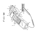
- Figure 1A is a perspective view of a first embodiment of the thermal printer according to this invention.
- Figure 1B is a perspective view of a second embodiment of the thermal lable printer according to this invention;
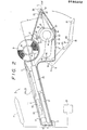
- Figure 2 is a sectional side view of the first and second embodiments showing its internal structure;
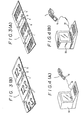
- Figure 3A is a perspective view of a segment of a first label strip;
- Figure 3B is a perspective view of a segment of a second label strip;
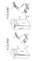
- Figure 4A is a perspective view showing how the thermal printer according to the first embodiment is connected with a microcomputer;
- Figure 4B is a perspective view showing how the thermal printer according to the second embodiment is connected with a microcomputer;
- Figure 5A is a perspective view showing how the thermal label printer according to the first embodiment is connected with a host computer;
- Figure 5B is a perspective view showing how the thermal printer according to the second embodiment is connected with a host computer;
- Fiugre 6 is a perspective view of a
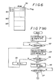
data memory 30; and - Figure 7 is a flowchart showing the process of the reading and determination of the data.
- An embodiment of the thermal label printer according to this invention will now be explained with reference to the accompanying drawings.
- An embodiment of the thermal printer according to this invention will now be explained with regard to the application thereof to a parcel transportation system.
- With reference to Figures 1A and 1B, the thermal printer according to this invention is a desk-top type consisting of a
main unit 2 having aflat bottom surface 3 which enables the printer to be placed on any desired supporting surface. Themain unit 2 is provided on Its top surface with data and command entry means consisting of a keyboard 6 comprising a numeric pad 4 andvarious function keys 5, and at a position above the keyboard with adisplay 7 such as a liquid crystal display, for example. Themain unit 2 is provided with apower switch 8 on one side and an open/close button 9 on each side. Themain unit 2 is further provided at an upper portion with asupport member 10 for holding a thermal label roll R which consists of a thermal label strip T wound into a roll, the arrangement being such that after labels L are printed and detached the labels L are discharged from a front portion of the unit. - At the rear end of the
main unit 2 are provided asocket 12 for connecting apen scanner 11 and asocket 13 for connecting abattery 27 to a battery charger which will be described later. Thenumeral 14 denotes the discharge outlet for the backing sheet S. - In the Figure 1A embodiment, the
pen scanner 11 is used for reading a bar code B printed on a shelf tag F and representing a merchandise code or the like and the data thus read is input to thethermal label printer 1. - In. the Figure 1B embodiment, the
pen scanner 11 can be used to read a despatch slip or the slip number bar code on a label F already affixed to a parcel. - With reference to Figure 2, the thermal label strip T passes from the thermal label roll R on the
support member 10 into alabel strip passage 18 via aposition sensor 15 and theguide rollers 17 of anupper press member 16. - As shown in Figures 3A and 3B, the label strip T consists of a backing sheet S coated with a separating agent and having a plurality of labels L, each of which is coated with an adhesive, detachably adhered continuously along its length.
- On the labels L of the thermal label strip T shown in Figure 3A is printed information I such as a bar code B representing a merchandise code or manufacturing code, a department code and a price. The backing sheet S is provided with holes D which are for position detection purposes.
- On the labels L of the thermal label strip T shown in Figure 3B is printed a parcel destination code I which corresponds to the bar code B of the slip number, and the backing sheet S is provided with holes D which are for position detection purposes. The holes D can also be utilized for conveyance purposes by engagement with the conveyor roller 19 (Figure 2). The thermal print medium is not limited to the said labels; depending on how the medium is going to be used, tags or the like not coated with adhesive may also be used.
- The holes D can also be utilized for conveyance purposes by engagement with the conveyor roller 19 (Figure 2).
- Reverting to Figure 2, the thermal label strip T passes via the
conveyor roller 19 to athermal print head 20 and a.platen 21, is redirected at theplaten 21 portion, where the labels L are peeled off, so that just the backing strip is directed back to engagement with theconveyor roller 19, guided by theguide rollers 23 of thelower press member 22, and the backing sheet S then feeds out from themain unit 2 via thedischarge outlet 14. A bending pin P (shown by a phantom line) may be provided in front of theplaten 21 to form the label peeling means which peels the labels L from the backing sheet S as the backing sheet S is redirected. - The loading of the label strip T is accomplished by working the open/
close buttons 9 to allow thebottom cover 24 section, which includes theplaten 21 and thelower press member 22, to swing downwardly aboutpivots 25, thereby making it possible to insert the roll of thermal label strip T. Any conventional type of opening/closing mechanism may be used for this purpose, so details thereof are herein omitted. Theconveyor roller 19 is driven by the stepped rotation action of, a stepping motor M so as to move the thermal label strip T in the required direction for printing and conveyance. - The
main unit 2 houses acontrol circuit 26. Thiscontrol circuit 26 is connected to thebattery 27, aninterface 28 for data Input from and output to external devices, aROM program memory 29 for communication and control programs, aRAM data memory 30, and the keyboard 6. Thedisplay 7,sensor 15,thermal print head 20 and stepping motor M are also connected to thecontrol circuit 26 and are thereby controlled by thecontrol circuit 26. Thebattery 27 is a rechargeable type and can be connected via thesocket 13 to anexternal battery charger 31. - Figure 4A shows the thermal label printer connected to a
microcomputer 32 to allowdata 1/O operations therebetween. Data can be transferred to themicrocomputer 32 via thesocket 12 and acable 33. - Figure 4B shows the thermal printer connected to a
microcomputer 32 to allow data I/O operations therebetween. - Figures 5A and 58 show an
acoustic coupler 34 being used to link therespective printers 1 to ahost computer 37 via atelephone 35, by means cf a wired orwireless link 36. - The operation of the first embodiment will now be explained with reference to an application for replenishing stock at a supermarket or the like.
- The operator carries the
thermal label printer 1 and thepen scanner 11 to a merchandise display shelf or rack where he uses it to scan a shelf tag F, thereby inputting the merchandise code and other relevant data into thethermal label printer 1. The operator then uses the keys of the numeric pad 4 to input the quantity of merchandise to be ordered in order to bring the stock up to the desired level. The data being inputted is displayedonthe display 7 to enable its accuracy to be confirmed. The operator then moves on to succeeding shelves and repeats the same sequence of operations. -The input data is temporarily stored in thedata memory 30 so that after the task of inputting the order cata has been completed, it can be transmitted to amicrocomputer 32 or ahost computer 37 via theinterface 28 and thesocket 12, as shown in Figures 4 and 5. - The_required labels may be printed out by the
printer 1 after the input order data has been processed and the ordered merchandise has arrived. This is possible because the merchandise codes, order quantity data and other such requisite information are stored in the memory means 30, so that the operator need only press thefunction key 5 marked PR, which causes theconveyor roller 19 to advance the thermal label strip T and activate thethermal print head 20 to print the labels L with the required bar codes B corresponding to the said stored information. Also, as the backing sheet S is redirected at theplaten 21 the labels L are peeled from the backing sheet S and fed out from themain unit 2, so that each label can be manually taken and applied to the merchandise (not illustrated). - Thus the labels can be printed just by pressing the PR function key, eliminating the need to manually input each and every merchandise code and quantity data such as has been conventionally required. An application roller 38 (shown by a phantom line in Figure 2) may be provided in front of the
platen 21 if large numbers of labels need to be applied. - The printer according to this invention will now be described with reference to the reduced-price selling of merchandise at closing time by supermarket tenant stores, such as butchers, greengrocers and the like.
- Conventionally, such stores have employed a measuring printer or like means to weight their merchandise beforehand and apply labels thereto printed with prices corresponding to the measured weight. However, when closing time approaches, such stores cut their prices in order to clear their stock that day, as the value of such merchandise lies in how fresh it is.
- However, because the conventional measuring printers are located in a merchandise arrival area or other specified location, it has been necessary to check the freshness of the merchandise or the state of,any damage thereto while printing out the labels, which is troublesome. In addition, it made it difficult to collect price data on merchandise that had been reduced in price for such selling, thereby causing problems between tenants and the supermarket owner when rents were calculated.
- With the
present printer 1, thepen scanner 11 can be used to scan a printed bar code corresponding to a price reduced to a preset level, or the reduced price input via the numeric pad 4, for printing on a label L which is- then affixed to the merchandise to Indicate the reduced price, while at the same time the reduced price data is stored in thedata memory 30 for subsequent uploading to amicrocomputer 32 orhost computer 37 where the reduced price data can be processed into slips, providing accurate handling of such data, and thereby minimizing disputes with the supermarket owner. - The operation of the second embodiment will now be explained with reference to Figures 6 and 7.
- Parcels coming from the despatcher are already printed with the slip number bar code B. The thermal printer according to the present invention is used at the stage prior to the sorting of the parcels by destination area to provide each parcel with a destination code I in a numeric form that can be understood by the sorter and which corresponds to the said bar code B.
- Tnus, slip number, destination and other necessary information is input into the
microcomputer 32 or thehost computer 37 at the parcel collection stage, and at the stage prior to the sorting theprinter 1 receives fromtne microcomputer 32 orhost computer 37 in the form of computer data the slip number I and the corresponding bar code B. Steps S1 to S6 show this process; N indicates the order in which the data is received. The data thus received is stored in a specific memory area M1 of thedata memory 30. - The sorter scans the slip number bar code B with the
pen scanner 11 to fiput the data into theprinter 1. This input data is stored in a specific memory area M2 of the data memory 30 (steps S7 and S8). The numeric pad 4 is also used for input when necessary. The input data can be dispiayed on thedisplay 7 for confirmation purposes. - In steos S8 to S17 it is determined whether the data (slip numbers of parcels at the collection stage) received from the computer matches the data that has just been read (i.e. the slip number actually attached to a parcel). This matching is done in steps S10 and S11; If the data match, the
control circuit 26 outputs a print command, the destination code I corresponding to the slip number is printed on a label L at the thermal print head 20 (step S12), and a label L is peeled from the backing sheet S by the bending of the backing sheet S at theplaten 21 and fed out from themain unit 2 so it can be manually taken and stuck on the parcel, forming a destination code I indication so as to enable a sorter to see the code and sort the parcel accordingly. - Instead of such sorting by the human eye, a destination bar code may be printed on the label L and read by a different scanner and sorted automatically. (This is not illustrated.) An application roller 38 (shown by a phantom line in Figure 2) may be provided in front of the
platen 21 if large numbers of lapels are involved. - When, owing to confusion, a parcel has gone astray and the expected reading is not obtained, or when a parcel that has been misrouted is read, the data is stored as non-matching .data. Specifically, when a match is made with the data of the printed label, a flag goes ON (step S13) and when no match is made the flag stays in the OFF state. In the case of a misrouted parcel being read, so that the data input is determined as differing from the received daia in step S15, the read data that has been stored in the memory area M2 is transferred to the memory area M3 (step S16). On the basis of this read data it is determined whether a parcel is missing or the wrong parcel, and this information is stored in the memory and displayed on the
display 7 or transferred to themicrocomputer 32 or thehost computer 37 for parcel-error processing (steps S19 and S20). - The structure of the thermal printer according to this invention can be simplified, if desired, by omitting the keyboard and providing only the pen scanner or a touch scanner as the data input means, and, further, by also omitting the display. In such a case another socket for input may be provided in addition to the
socket 12 already described. Where it is desired that the thermal printer according to this invention be easily portable, a fixed or detachable type handle (not shown) may be provided on the bottom of themain unit 2. - Although a first embodiment of the present Invention has been described with reference to an application for replenishing stock or reduced-price selling, the invention is not limited to these applications but can also be used for the input and output of data relating to various types of merchandise and other articles, using a pen scanner, keyboard or any of the various other kinds of data I/O means, such data uploaded to and/or received from a central computer and labels printed accordingly, and as such is widely applicable when labels have to be printed in accordance with various types of data transaction, all applications which could not be handled by conventional printers.
- Although a second embodiment of the invention has been described with respect to an application for despatching parcels, the invention is not limited to this application but can also be used for the input and output of data relating to various types of merchandise and other articles, using a pen scanner, keyboard or any of the various other kinds of data I/O means, for the comparison and determination of data received from a central computer for printing labels, and as such is useful for data indication for managing and keeping track of merchandise. In addition, because when on the basis of the comparison it is determined that the cata do not match, the data is stored temporarily in the memory and can be communicated to a central computer, it becomes possible to accurr-ulate data on parcels which have gone adrift or have been erroneously included.
- Thus, the thermal printer according to this invention is able to print labels based on various data from various sources, and as such is therefore applicable to a wide range of tasks, many of which could not be handled oy conventional printers.
- Some of the ootential applications for the present thermal printer include inventory control of retail outlets, management of business data files, prining of blood data cards and sample tube labels at blood banks, printing of bar code labels for patient charts and medical certificates at nospitais and clinics, process parts and inventory control in factories, in tne treignt business for the printing of confirmation labels at parcel reception/despatch points, and for the management of customer data, and data and printing of labels relating to outside suppliers at department stores and supermarkets.

Claims (3)
Applications Claiming Priority (4)
| Application Number | Priority Date | Filing Date | Title |
|---|---|---|---|
| JP82199/85 | 1985-04-19 | ||
| JP60082199A JPS61244734A (en) | 1985-04-19 | 1985-04-19 | Thermal label printer |
| JP60089004A JPS61248760A (en) | 1985-04-26 | 1985-04-26 | Thermal printer |
| JP89004/85 | 1985-04-26 |
Publications (4)
| Publication Number | Publication Date |
|---|---|
| EP0199252A2 true EP0199252A2 (en) | 1986-10-29 |
| EP0199252A3 EP0199252A3 (en) | 1987-08-19 |
| EP0199252B1 EP0199252B1 (en) | 1991-07-03 |
| EP0199252B2 EP0199252B2 (en) | 1998-03-04 |
Family
ID=26423215
Family Applications (1)
| Application Number | Title | Priority Date | Filing Date |
|---|---|---|---|
| EP86105135A Expired - Lifetime EP0199252B2 (en) | 1985-04-19 | 1986-04-14 | A combination of a termal label printer and means for sorting parcels, and amethod for checking and sorting parcels. |
Country Status (2)
| Country | Link |
|---|---|
| EP (1) | EP0199252B2 (en) |
| DE (2) | DE3680019D1 (en) |
Cited By (15)
| Publication number | Priority date | Publication date | Assignee | Title |
|---|---|---|---|---|
| EP0265146A2 (en) * | 1986-10-14 | 1988-04-27 | Mars Incorporated | Portable data scanner with removable modular printer |
| FR2633410A1 (en) * | 1988-06-22 | 1989-12-29 | Monarch Marking Systems Inc | RECONFIGURABLE PRINTER |
| EP0430609A1 (en) * | 1989-11-24 | 1991-06-05 | Kabushiki Kaisha Shinsei Industries | Electronic labeller |
| EP0467014A2 (en) | 1990-07-16 | 1992-01-22 | Symbol Technologies, Inc. | Arrangement and method for a point-of sale site |
| EP0471530A1 (en) * | 1990-08-16 | 1992-02-19 | KEYMED (MEDICAL & INDUSTRIAL EQUIPMENT) LIMITED | Labelling reusable medical instruments |
| US5382779A (en) * | 1993-05-07 | 1995-01-17 | Digicomp Research Corporation | Shelf price label verification apparatus and method |
| US5493107A (en) * | 1993-05-07 | 1996-02-20 | Digicomp Research Corporation | Shelf price label and product placement verification method and apparatus |
| WO1996031839A1 (en) * | 1995-04-05 | 1996-10-10 | Csir | Stock labelling |
| US5640002A (en) * | 1995-08-15 | 1997-06-17 | Ruppert; Jonathan Paul | Portable RF ID tag and barcode reader |
| US5710416A (en) * | 1995-10-05 | 1998-01-20 | Ncr Corporation | Price verifier |
| US5978772A (en) * | 1996-10-11 | 1999-11-02 | Mold; Jeffrey W. | Merchandise checkout system |
| EP1078859A1 (en) * | 1999-08-27 | 2001-02-28 | Monarch Marking Systems, INC. | Hand-held labeller with data entry device assembly |
| US6340115B1 (en) | 1987-12-28 | 2002-01-22 | Symbol Technologies, Inc. | Card reader and method for completing transactions |
| US6644549B1 (en) | 1987-12-28 | 2003-11-11 | Symbol Technologies, Inc. | Portable terminal with real-time database access, printing and display |
| NL1029199C2 (en) * | 2005-06-07 | 2006-12-08 | Green Mountain B V | Repricing goods for sale, uses barcode scanner to record product type and price and send this information to printer used to generate adhesive labels with new price on them |
Families Citing this family (1)
| Publication number | Priority date | Publication date | Assignee | Title |
|---|---|---|---|---|
| US6937998B1 (en) | 1987-12-28 | 2005-08-30 | Symbol Technologies, Inc. | Arrangement for and method of expediting transactions based on a customer's proximity to the transactions |
Citations (2)
| Publication number | Priority date | Publication date | Assignee | Title |
|---|---|---|---|---|
| EP0126898A2 (en) * | 1981-05-29 | 1984-12-05 | Monarch Marking Systems, Inc. | Hand-held labelling machine |
| DE3413887A1 (en) * | 1983-04-14 | 1984-12-13 | Monarch Marking Systems, Inc., Dayton, Ohio | HAND LABELING DEVICE WITH A THERMOGRAPHIC RECORDING DEVICE |
-
1986
- 1986-04-14 DE DE8686105135T patent/DE3680019D1/en not_active Expired - Lifetime
- 1986-04-14 DE DE198686105135T patent/DE199252T1/en active Pending
- 1986-04-14 EP EP86105135A patent/EP0199252B2/en not_active Expired - Lifetime
Patent Citations (2)
| Publication number | Priority date | Publication date | Assignee | Title |
|---|---|---|---|---|
| EP0126898A2 (en) * | 1981-05-29 | 1984-12-05 | Monarch Marking Systems, Inc. | Hand-held labelling machine |
| DE3413887A1 (en) * | 1983-04-14 | 1984-12-13 | Monarch Marking Systems, Inc., Dayton, Ohio | HAND LABELING DEVICE WITH A THERMOGRAPHIC RECORDING DEVICE |
Cited By (24)
| Publication number | Priority date | Publication date | Assignee | Title |
|---|---|---|---|---|
| EP0265146A3 (en) * | 1986-10-14 | 1989-10-25 | Mars Incorporated | Portable data scanner with removable modular printer |
| EP0265146A2 (en) * | 1986-10-14 | 1988-04-27 | Mars Incorporated | Portable data scanner with removable modular printer |
| US6340115B1 (en) | 1987-12-28 | 2002-01-22 | Symbol Technologies, Inc. | Card reader and method for completing transactions |
| US6644549B1 (en) | 1987-12-28 | 2003-11-11 | Symbol Technologies, Inc. | Portable terminal with real-time database access, printing and display |
| FR2633410A1 (en) * | 1988-06-22 | 1989-12-29 | Monarch Marking Systems Inc | RECONFIGURABLE PRINTER |
| EP0430609A1 (en) * | 1989-11-24 | 1991-06-05 | Kabushiki Kaisha Shinsei Industries | Electronic labeller |
| EP0853290B1 (en) * | 1990-07-16 | 2002-11-27 | Symbol Technologies, Inc. | Method of processing products in a point-of-sale system. |
| EP0853290A2 (en) * | 1990-07-16 | 1998-07-15 | Symbol Technologies, Inc. | Arrangement for and method of processing products at a point-of-sale site |
| EP0467014B1 (en) * | 1990-07-16 | 1999-08-04 | Symbol Technologies, Inc. | Arrangement for a point-of sale site |
| EP1248223A3 (en) * | 1990-07-16 | 2006-04-26 | Symbol Technologies, Inc. | Arrangement for and method of processing products at a point-of-sale |
| EP0467014A2 (en) | 1990-07-16 | 1992-01-22 | Symbol Technologies, Inc. | Arrangement and method for a point-of sale site |
| EP1248223A2 (en) * | 1990-07-16 | 2002-10-09 | Symbol Technologies, Inc. | Arrangement for and method of processing products at a point-of-sale |
| EP0471530A1 (en) * | 1990-08-16 | 1992-02-19 | KEYMED (MEDICAL & INDUSTRIAL EQUIPMENT) LIMITED | Labelling reusable medical instruments |
| US5493107A (en) * | 1993-05-07 | 1996-02-20 | Digicomp Research Corporation | Shelf price label and product placement verification method and apparatus |
| US5382779A (en) * | 1993-05-07 | 1995-01-17 | Digicomp Research Corporation | Shelf price label verification apparatus and method |
| WO1996012243A1 (en) * | 1994-10-18 | 1996-04-25 | Digicomp Research Corporation | Shelf price label and product placement verification method and apparatus |
| WO1996031839A1 (en) * | 1995-04-05 | 1996-10-10 | Csir | Stock labelling |
| US5640002A (en) * | 1995-08-15 | 1997-06-17 | Ruppert; Jonathan Paul | Portable RF ID tag and barcode reader |
| US5710416A (en) * | 1995-10-05 | 1998-01-20 | Ncr Corporation | Price verifier |
| US5978772A (en) * | 1996-10-11 | 1999-11-02 | Mold; Jeffrey W. | Merchandise checkout system |
| EP1078859A1 (en) * | 1999-08-27 | 2001-02-28 | Monarch Marking Systems, INC. | Hand-held labeller with data entry device assembly |
| US6652170B1 (en) | 1999-08-27 | 2003-11-25 | Paxar Americas, Inc. | Portable printer and data entry device assembly |
| US7073717B1 (en) | 1999-08-27 | 2006-07-11 | Paxar Americas, Inc. | Portable printer and data entry device connected thereto assembly |
| NL1029199C2 (en) * | 2005-06-07 | 2006-12-08 | Green Mountain B V | Repricing goods for sale, uses barcode scanner to record product type and price and send this information to printer used to generate adhesive labels with new price on them |
Also Published As
| Publication number | Publication date |
|---|---|
| DE199252T1 (en) | 1987-02-26 |
| EP0199252B2 (en) | 1998-03-04 |
| DE3680019D1 (en) | 1991-08-08 |
| EP0199252B1 (en) | 1991-07-03 |
| EP0199252A3 (en) | 1987-08-19 |
Similar Documents
| Publication | Publication Date | Title |
|---|---|---|
| US4746932A (en) | Thermal label printer having I/O capabilities | |
| US4734713A (en) | Thermal printer | |
| US4734710A (en) | Thermal label printer | |
| EP0199252A2 (en) | Thermal label printer | |
| US4706095A (en) | Portable thermal label printer | |
| US4365148A (en) | Data processing system | |
| US4706096A (en) | Unit type thermal label printer | |
| US5153842A (en) | Integrated circuit package label and/or manifest system | |
| US4807177A (en) | Multiple format hand held label printer | |
| US5292008A (en) | Postal tray label apparatus and method | |
| JPH10187843A (en) | Delivery article check system | |
| EP0200945B1 (en) | Thermal label printer | |
| JP4184483B2 (en) | Delivery slip issuing system | |
| JP2000117000A (en) | Laundry management device | |
| JP5089671B2 (en) | Sorting system, delivery destination specifying method and delivery destination specifying program | |
| JPS61259938A (en) | Thermal label printer | |
| JPH0624951Y2 (en) | Delivery service for ski, golf and parcel delivery | |
| JPH0542753A (en) | Label printer | |
| JPS61259937A (en) | Thermal label printer | |
| JP2003141227A (en) | Stocktaking system of inventory item | |
| JPH0575626B2 (en) | ||
| JPH0821047B2 (en) | Shipment management equipment | |
| JP3760719B2 (en) | Picking equipment | |
| JPS63112314A (en) | Article collecting equipment | |
| EP0118517A1 (en) | Labels |
Legal Events
| Date | Code | Title | Description |
|---|---|---|---|
| PUAI | Public reference made under article 153(3) epc to a published international application that has entered the european phase |
Free format text: ORIGINAL CODE: 0009012 |
|
| AK | Designated contracting states |
Kind code of ref document: A2 Designated state(s): DE FR GB |
|
| EL | Fr: translation of claims filed | ||
| DET | De: translation of patent claims | ||
| PUAL | Search report despatched |
Free format text: ORIGINAL CODE: 0009013 |
|
| RHK1 | Main classification (correction) |
Ipc: G06K 15/10 |
|
| AK | Designated contracting states |
Kind code of ref document: A3 Designated state(s): DE FR GB |
|
| 17P | Request for examination filed |
Effective date: 19880216 |
|
| 17Q | First examination report despatched |
Effective date: 19890627 |
|
| GRAA | (expected) grant |
Free format text: ORIGINAL CODE: 0009210 |
|
| AK | Designated contracting states |
Kind code of ref document: B1 Designated state(s): DE FR GB |
|
| REF | Corresponds to: |
Ref document number: 3680019 Country of ref document: DE Date of ref document: 19910808 |
|
| ET | Fr: translation filed | ||
| PLBI | Opposition filed |
Free format text: ORIGINAL CODE: 0009260 |
|
| 26 | Opposition filed |
Opponent name: ESSELTE METO INTERNATIONAL PRODUKTIONS GMBH Effective date: 19920402 |
|
| PLAW | Interlocutory decision in opposition |
Free format text: ORIGINAL CODE: EPIDOS IDOP |
|
| PLAW | Interlocutory decision in opposition |
Free format text: ORIGINAL CODE: EPIDOS IDOP |
|
| PUAH | Patent maintained in amended form |
Free format text: ORIGINAL CODE: 0009272 |
|
| STAA | Information on the status of an ep patent application or granted ep patent |
Free format text: STATUS: PATENT MAINTAINED AS AMENDED |
|
| 27A | Patent maintained in amended form |
Effective date: 19980304 |
|
| AK | Designated contracting states |
Kind code of ref document: B2 Designated state(s): DE FR GB |
|
| ET3 | Fr: translation filed ** decision concerning opposition | ||
| REG | Reference to a national code |
Ref country code: GB Ref legal event code: IF02 |
|
| PGFP | Annual fee paid to national office [announced via postgrant information from national office to epo] |
Ref country code: GB Payment date: 20050329 Year of fee payment: 20 |
|
| PGFP | Annual fee paid to national office [announced via postgrant information from national office to epo] |
Ref country code: FR Payment date: 20050419 Year of fee payment: 20 |
|
| REG | Reference to a national code |
Ref country code: GB Ref legal event code: PE20 |
|
| PGFP | Annual fee paid to national office [announced via postgrant information from national office to epo] |
Ref country code: DE Payment date: 20050530 Year of fee payment: 20 |
|
| PG25 | Lapsed in a contracting state [announced via postgrant information from national office to epo] |
Ref country code: GB Free format text: LAPSE BECAUSE OF EXPIRATION OF PROTECTION Effective date: 20060413 |