EP0198373A2 - Electrical vaporisation device for insecticides - Google Patents
Electrical vaporisation device for insecticides Download PDFInfo
- Publication number
- EP0198373A2 EP0198373A2 EP86104684A EP86104684A EP0198373A2 EP 0198373 A2 EP0198373 A2 EP 0198373A2 EP 86104684 A EP86104684 A EP 86104684A EP 86104684 A EP86104684 A EP 86104684A EP 0198373 A2 EP0198373 A2 EP 0198373A2
- Authority
- EP
- European Patent Office
- Prior art keywords
- plate
- air
- heating
- slot
- housing
- Prior art date
- Legal status (The legal status is an assumption and is not a legal conclusion. Google has not performed a legal analysis and makes no representation as to the accuracy of the status listed.)
- Granted
Links
Images

Classifications
-
- A—HUMAN NECESSITIES
- A01—AGRICULTURE; FORESTRY; ANIMAL HUSBANDRY; HUNTING; TRAPPING; FISHING
- A01M—CATCHING, TRAPPING OR SCARING OF ANIMALS; APPARATUS FOR THE DESTRUCTION OF NOXIOUS ANIMALS OR NOXIOUS PLANTS
- A01M1/00—Stationary means for catching or killing insects
- A01M1/20—Poisoning, narcotising, or burning insects
- A01M1/2022—Poisoning or narcotising insects by vaporising an insecticide
- A01M1/2061—Poisoning or narcotising insects by vaporising an insecticide using a heat source
- A01M1/2077—Poisoning or narcotising insects by vaporising an insecticide using a heat source using an electrical resistance as heat source
-
- Y—GENERAL TAGGING OF NEW TECHNOLOGICAL DEVELOPMENTS; GENERAL TAGGING OF CROSS-SECTIONAL TECHNOLOGIES SPANNING OVER SEVERAL SECTIONS OF THE IPC; TECHNICAL SUBJECTS COVERED BY FORMER USPC CROSS-REFERENCE ART COLLECTIONS [XRACs] AND DIGESTS
- Y10—TECHNICAL SUBJECTS COVERED BY FORMER USPC
- Y10S—TECHNICAL SUBJECTS COVERED BY FORMER USPC CROSS-REFERENCE ART COLLECTIONS [XRACs] AND DIGESTS
- Y10S261/00—Gas and liquid contact apparatus
- Y10S261/88—Aroma dispensers
- Y10S261/89—Electrically heated aroma dispensers
Definitions
- the invention relates to an electrical device for vaporizing insecticidal active substance from platelets with an upright, electrical heating plate in a housing and a platelet channel, which runs approximately horizontally past the heating surface of the heating plate, with platelet insertion slot on the housing side surface and with contact pins for insertion into a socket or the like on the back of the case.
- An electrical evaporation device of this type is described in DE-OS 27 30 855.
- a disk-shaped heater and an active substance plate are arranged upright against one another.
- the plate is located immediately behind a grid that is permeable to the vaporized active substance and extends essentially vertically during operation and forms a part of the front of the housing.
- the plate is brought into the working position via a horizontal channel through a slot in the side surface of the housing. The channel can extend across the housing.
- the active ingredient is evaporated practically exclusively by diffusion through the open grid on the front of the housing; Ventilation slots provided on the rear of the housing are practically inaccessible for the vapors coming from the plate.
- a disadvantage of the known device is that the vaporized substance can normally not be distributed in the surrounding space by convection but only by molecular movements due to the concentration gradient maintained by the vaporization.
- the formation of condensate of the vaporized active substance from the corresponding outlet openings is particularly disadvantageous.
- a fan may have to be used to distribute or circulate the vaporized substance.
- the associated housing consists of a lower chamber with air inlet openings and an upper chamber with air outlet openings, an electrical heating resistor is arranged at the boundary between the lower and upper chamber and an active ingredient tablet is arranged vertically above it on a grid of pins or prongs.
- the tablet, the grid supporting it and the heating element are designed and arranged in such a way that the heating element - apart from its actual function, namely the vaporization of the active ingredient - by convection an air flow in the vertical direction through the air inlet openings into the housing, in the housing around the Active ingredient tablet around and then through the air outlet openings again from the housing.
- the resistance provided for heating the active ingredient tablet must be heated in the known device far above the temperature required for the active ingredient to evaporate because there is no direct contact between the tablet and the heating element. A large part of the heating energy is therefore lost unused and very high heating temperatures are required to drive substances that are difficult to evaporate out of the respective tablet.
- Another disadvantage is the glow lamp which indicates the function in the known device, because the lamp there deflects the convective air flow and thus interferes with the removal of the active ingredient.
- the invention has for its object to provide an electrical device for vaporizing platelets or maize containing insecticidal active ingredient, in which a convection gas stream is concentrated in the area of the platelet to be vaporized and, despite the relatively low heating and device temperature, formation of active ingredient condensate at the device outlet is avoided.
- the device should also be designed so that the refilling or replacement of active ingredient platelets can be done without difficulty from the side without the risk of injury from contact with current-carrying and / or heated elements.
- the solution according to the invention for the electrical device of the type mentioned above with an upright heating plate and a plate insertion channel horizontally passing its vertical heating surface is that in front of the heating surface a chimney, closed except for an air intake slot on the front of the housing and an evaporation slot on the top of the housing Air duct is arranged that the air duct between the air intake slot and the lower edge of the heating plate above a function indicator lamp and is bent from the horizontal to the vertical in front of the lower edge of the heating plate and that the evaporation slot is located vertically above the plate which may be pressed flat against the heating surface of the heating plate .
- the flowing air is guided past the tablet heated to the vaporization temperature in the manner of the chimney air, so that the air entrains the vaporized product.
- the air duct inside the housing begins, initially approximately horizontally on one provided in the front of the housing Suction slot, which is located above a function indicator lamp, for example. Malfunctions emanating from the lamp are therefore not to be expected.
- the duct is bent vertically below the heating plate in order to ensure that the respectively inserted plate and the heating plate or their heating surface stand upright in the convective air flow and a temperature gradient arises between the sucked-in and discharged air.
- the design ensures that the temperature rises in the direction of the evaporation slot, which ensures that the active ingredient actually evaporates upwards and the formation of condensate at the evaporation opening is largely avoided despite the relatively low housing temperature.
- the device according to the invention has a platelet insertion channel which extends in the horizontal direction parallel to the heating surface and past the heating plate in such a way that the air duct and the platelet channel cross in the area in front of the heating surface. Because of the strong heating in the area of the heating surface and the chimney effect of the part of the air duct above the heating plate, in addition to the suction slot on the front of the housing, air is also sucked in through the plate insertion and removal slots on the housing side surfaces. The air sucked in through three slots of a certain total cross section must therefore be "blown off” through the much smaller cross section of the evaporation slot. The air loaded with the vaporized active substance is thus greatly accelerated on the way from the heating plate to the evaporation slot in the sense of the continuity equation of flows.
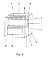
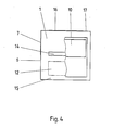
- the electrical device provided for vaporizing insecticidal active substance platelets has a housing with a front cap 1 and a rear side cap 3 provided with contact pins 2 for insertion into a socket. Front cap 1 and rear side cap 3 are coupled along the dashed connecting line 4.
- the housing designated overall by 5, has on each of its side faces 6 a plate insertion slot 7 for inserting and removing active substance plates.
- the opposing plate insertion slots 7 are connected to one another by a plate channel 8.
- the platelet channel 8 leads directly past the heating surface 9 of a heating plate 10 which is arranged upright in the interior of the device.
- the heating plate 10 is supplied with electrical energy via the contact pins 2.
- an active ingredient platelet inserted into the platelet channel 8 lies flat against the heating surface 9.
- the glow lamp 11 is also supplied with voltage via the contact pins 2.
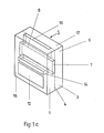
- an active substance platelet introduced into the platelet channel 8 and at least the heating surface 9 of the heating plate 10 are placed in an air channel which acts as a chimney and is designated overall by 13.
- the air duct has an intake slot 14 on the front 15 of the housing and an outlet or.
- Abdampfschlitz 16 on the housing surface 17 above the position of the active wafer to the heating plate 10.
- the air duct 13 of the heating surface 9 is formed so that an inserted in 'platelet agent channel 8 platelets is sufficient space in the area. Shortly above the plate, the air duct 13 is narrowed considerably, for example to a few mm.
- the air duct 13 can be relatively wide, in such a way that sufficient amounts of air can sweep past the inserted plate in the direction of the evaporation slot 16. Because of the initially relatively wide and then greatly reduced air duct cross section, a strong convection current with chimney effect is generated in the area above the plate and, accordingly, the vaporized active ingredient is blown out of the evaporation slot 16 at a relatively high speed in the direction of the arrow 18.
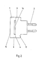
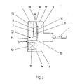
- the air duct 13 On its suction side, the air duct 13 is equipped with a bend 19 below the heating plate 10 in order to enable suction from the front of the device 15 and in this way a function indicator lamp, e.g. the glow lamp 11 to keep out of the convection current.
- a function indicator lamp e.g. the glow lamp 11 to keep out of the convection current.
Abstract
Description
Die Erfindung betrifft ein elektrisches Gerät zum Verdampfen von insektizidem Wirkstoff aus Plättchen mit einer aufrecht stehenden, elektrischen Heizplatte in einem Gehäuse und einem an der Heizfläche der Heizplatte etwa horizontal vorbeiführenden Plättchenkanal mit Plättcheneinführschlitz an der Gehäuseseitenfläche sowie mit Kontaktstiften für den Einschub in eine Steckdose oder dergleichen an der Gehäuserückseite.The invention relates to an electrical device for vaporizing insecticidal active substance from platelets with an upright, electrical heating plate in a housing and a platelet channel, which runs approximately horizontally past the heating surface of the heating plate, with platelet insertion slot on the housing side surface and with contact pins for insertion into a socket or the like on the back of the case.
Eine elektrische Verdampfungseinrichtung dieser Art wird in der DE-OS 27 30 855 beschrieben. In dem zugehörigen diskusförmigen Gehäuse werden eine scheibenförmige Heizung und eine Wirkstoffplatte aufrecht aneinanderliegend angeordnet. Die Platte befindet sich unmittelbar hinter einem für den verdampften Wirkstoff durchlässigen, sich bei Betrieb im wesentlichen vertikal erstreckenden Gitter, das einen Teil der Vorderseite des Gehäuses bildet. Die Platte wird über einen horizontalen Kanal durch einen in der Gehäuseseitenfläche befindlichen Schlitz in die Arbeitsposition gebracht. Der Kanal kann sich quer durch das Gehäuse erstrecken. Das Abdampfen des Wirkstoffs erfolgt praktisch ausschließlich durch Diffusion durch das offene Gitter auf der Gehäusevorderseite; an der Gehäuserückseite vorgesehene Be-und Entlüftungsschlitze sind für die von der Platte kommenden Dämpfe praktisch nicht zugänglich. Ein Nachteil des bekannten Geräts besteht darin, daß sich die verdampfte Substanz im Umgebungsraum normalerweise nicht durch Konvektion sondern nur durch Molekularbewegungen aufgrund des durch den Verdampfungs aufrecht erhaltenen Konzentrationsgefälles verteilen kann. Besonders nachteilig ist eine Kondensatbildung des verdampften Wirkstoffs aus den entsprechenden Austrittsöffnungen. Eventuell muß ein Ventilator zum Verteilen bzw. Umwälzen der verdampften Substanz herangezogen werden.An electrical evaporation device of this type is described in DE-OS 27 30 855. In the associated disc-shaped housing, a disk-shaped heater and an active substance plate are arranged upright against one another. The plate is located immediately behind a grid that is permeable to the vaporized active substance and extends essentially vertically during operation and forms a part of the front of the housing. The plate is brought into the working position via a horizontal channel through a slot in the side surface of the housing. The channel can extend across the housing. The active ingredient is evaporated practically exclusively by diffusion through the open grid on the front of the housing; Ventilation slots provided on the rear of the housing are practically inaccessible for the vapors coming from the plate. A disadvantage of the known device is that the vaporized substance can normally not be distributed in the surrounding space by convection but only by molecular movements due to the concentration gradient maintained by the vaporization. The formation of condensate of the vaporized active substance from the corresponding outlet openings is particularly disadvantageous. A fan may have to be used to distribute or circulate the vaporized substance.
Ein weiteres, in einen elektrischen Wandanschluß einzusteckendes Verdampfungsgerät für insektiziden Wirkstoff wird in der DE-OS 28 25 674 beschrieben. Das zugehörige Gehäuse besteht aus einer unteren Kammer mit Lufteinlaßöffnungen und einer oberen Kammer mit Luftaustaßöffnungen, an der Grenze zwischen unterer und oberer Kammer werden ein elektrischer Heizwiderstand und vertikal darüber auf einem Rost aus Stiften oder Zinken eine Wirkstofftablette angeordnet. Die Tablette, der sie tragende Rost und das Heizelement werden so ausgebildet und angeordnet, daß das Heizelement - außer seiner eigentlichen Aufgabe, nämlich dem Verdampfen des Wirkstoffs -durch Konvektion einen Luftstrom in vertikaler Richtung durch die Lufteinlaßöffnungen in das Gehäuse hinein, im Gehäuse um die Wirkstofftablette herum und dann durch die Luftauslaßöffnungen wieder aus dem Gehäuse heraus erzeugen kann. Der zum Aufheizen der Wirkstofftablette vorgesehene Widerstand muß im bekannten Gerät weit über die zum Abdampfen des Wirkstoffs an sich erforderliche Temperatur erhitzt werden, weil ein unmittelbarer Kontakt zwischen Tablette und Heizelement fehlt Ein großer Teil der Heizenergie geht daher ungenützt verloren und es sind sehr hohe Heiztemperaturen erforderlich, um schwer abdampfbare Substanzen aus der jeweiligen Tablette herauszutreiben. Nachteilig ist auch die im bekannten Gerät die Funktion anzeigende Glimmlampe, weil die Lampe dort eine Umlenkung des konvektiven Luftstroms bewirkt und damit das Abführen des Wirkstoffs stört.Another evaporation device for insecticidal active ingredient to be inserted into an electrical wall connection is described in DE-OS 28 25 674. The associated housing consists of a lower chamber with air inlet openings and an upper chamber with air outlet openings, an electrical heating resistor is arranged at the boundary between the lower and upper chamber and an active ingredient tablet is arranged vertically above it on a grid of pins or prongs. The tablet, the grid supporting it and the heating element are designed and arranged in such a way that the heating element - apart from its actual function, namely the vaporization of the active ingredient - by convection an air flow in the vertical direction through the air inlet openings into the housing, in the housing around the Active ingredient tablet around and then through the air outlet openings again from the housing. The resistance provided for heating the active ingredient tablet must be heated in the known device far above the temperature required for the active ingredient to evaporate because there is no direct contact between the tablet and the heating element. A large part of the heating energy is therefore lost unused and very high heating temperatures are required to drive substances that are difficult to evaporate out of the respective tablet. Another disadvantage is the glow lamp which indicates the function in the known device, because the lamp there deflects the convective air flow and thus interferes with the removal of the active ingredient.
Der Erfindung liegt die Aufgabe zugrunde, ein elektrisches Gerät zum Verdampfen von insektiziden Wirkstoff enthaltenden Plättchen bzw. Mais zu schaffen, in welchem ein Konvektionsgasstrom im Bereich des zu verdampfenden Plättchens konzentriert und trotz relativ niedriger Heiz-und Gerätetemperatur eine Wirkstoffkondensathildung am Geräteausgang vermieden wird. Das Gerät soll außerdem so ausgebildet werden, daß das Nachfüllen oder der Austausch von Wirkstoffplättchen ohne Schwierigkeiten von der Seite her ohne die Gefahr der Verletzung durch Berührung mit stromleitenden und/oder erhitzten Elementen erfolgen kann. Die erfindungsgemäße Lösung besteht für das elektrische Gerät eingangs genannter Art mit einer aufrecht stehenden Heizplatte und einem an deren vertikaler Heizfläche horizontal vorbeiführenden Plättcheneinführkanal darin, daß vor der Heizfläche ein als Kamin ausgebildeter, bis auf einen Luftansaugschlitz an der Gehäusevorderseite und einen Abdampfschlitz auf der Gehäuseoberseite geschlossener Luftkanal angeordnet ist, daß der Luftkanal zwischen Luftansaugschlitz und unterem Rand der Heizplatte oberhalb einer Funktionsanzeigelampe hinweggeführt und vor dem unteren Rand der Heizplatte aus der Horizontalen in die Vertikale abgeknickt ist und daß der Abdampfschlitz vertikal oberhalb des gegebenenfalls flach an die Heizfläche der Heizplatte angedrückten Plättchens liegt.The invention has for its object to provide an electrical device for vaporizing platelets or maize containing insecticidal active ingredient, in which a convection gas stream is concentrated in the area of the platelet to be vaporized and, despite the relatively low heating and device temperature, formation of active ingredient condensate at the device outlet is avoided. The device should also be designed so that the refilling or replacement of active ingredient platelets can be done without difficulty from the side without the risk of injury from contact with current-carrying and / or heated elements. The solution according to the invention for the electrical device of the type mentioned above with an upright heating plate and a plate insertion channel horizontally passing its vertical heating surface is that in front of the heating surface a chimney, closed except for an air intake slot on the front of the housing and an evaporation slot on the top of the housing Air duct is arranged that the air duct between the air intake slot and the lower edge of the heating plate above a function indicator lamp and is bent from the horizontal to the vertical in front of the lower edge of the heating plate and that the evaporation slot is located vertically above the plate which may be pressed flat against the heating surface of the heating plate .
In dem erfindungsgemäßen Gerät wird die strömende Luft nach Art der Kaminluft an der auf die Verdampfungstemperatur erhitzten Tablette vorbeigeführt, so daß die Luft das verdampfte Produkt mitnimmt. Der Luftkanal innerhalb des Gehäuses beginnt, zunächst etwa horizontal an einem in der Gehäusevorderseite vorgesehenen Ansaugschlitz, der sich beispielsweise oberhalb einer Funktionsanzeigelampe befindet. Von der Lampe ausgehende Funktionsstörungen sind also nicht zu erwarten. Innerhalb des Gehäuses wird der Kanal unterhalb der Heizplatte in die Vertikale abgeknickt, um zu erreichen, daß das jeweils eingelegte Plättchen und die Heizplatte bzw. deren Heizfläches aufrecht im konvektiven Luftstrom stehen und ein Temperaturgefälle zwischen angesaugter und abgeleiteter Luft entsteht. Durch die Konstruktion wird erreicht, daß die Temperatur in Richtung auf den Abdampfschlitz steigt, wodurch gewährleistet wird, daß der Wirkstoff tatsächlich nach oben hin abdampft und auch die Bildung von Kondensat an der Abdampföffnung trotz relativ niedriger Gehäusetemperatur weitestgehend vermieden wird.In the device according to the invention, the flowing air is guided past the tablet heated to the vaporization temperature in the manner of the chimney air, so that the air entrains the vaporized product. The air duct inside the housing begins, initially approximately horizontally on one provided in the front of the housing Suction slot, which is located above a function indicator lamp, for example. Malfunctions emanating from the lamp are therefore not to be expected. Inside the housing, the duct is bent vertically below the heating plate in order to ensure that the respectively inserted plate and the heating plate or their heating surface stand upright in the convective air flow and a temperature gradient arises between the sucked-in and discharged air. The design ensures that the temperature rises in the direction of the evaporation slot, which ensures that the active ingredient actually evaporates upwards and the formation of condensate at the evaporation opening is largely avoided despite the relatively low housing temperature.
Das erfindungsgemäße Gerät besitzt einen Plättcheneinführkanal, der sich in horizontaler Richtung parallel zur Heizfläche and der Heizplatte vorbei erstreckt, derart, daß sich der Luftkanal und der Plättchenkanal im Bereich vor der Heizfläche kreuzen. Wegen der im Bereich der Heizfläche starken Erhitzung und der Kaminwirkung des Teils des Luftkanals oberhalb der Heizplatte wird außer durch den Ansaugschlitz auf der Gehäusevorderseite auch Luft durch die Plättchenein-und -ausfuhrschlitze an den Gehäuseseitenflächen angesaugt. Die durch drei Schlitze eines bestimmten Gesamtquerschnitts angesaugte Luft muß somit durch den viel kleineren Querschnitt des Abdampfschlitzes "abgeblasen" werden. Die mit dem verdampften Wirkstoff beladene Luft wird also auf dem Wege von der Heizplatte zum Abdampfschlitz im Sinne der Kontinuitätsgleichung von Strömungen stark beschleunigt.The device according to the invention has a platelet insertion channel which extends in the horizontal direction parallel to the heating surface and past the heating plate in such a way that the air duct and the platelet channel cross in the area in front of the heating surface. Because of the strong heating in the area of the heating surface and the chimney effect of the part of the air duct above the heating plate, in addition to the suction slot on the front of the housing, air is also sucked in through the plate insertion and removal slots on the housing side surfaces. The air sucked in through three slots of a certain total cross section must therefore be "blown off" through the much smaller cross section of the evaporation slot. The air loaded with the vaporized active substance is thus greatly accelerated on the way from the heating plate to the evaporation slot in the sense of the continuity equation of flows.
Anhand der schematischen Darstellung eines Ausführungsbeispiels werden Einzelheiten der Erfindung erläutert. Es zeigen:
- Fig. 1 a, b und c perspektivische Ansichten eines Verdampfungsgeräts;
- Fig. 2 eine Draufsicht vertikal von oben auf das Gerät nach Fig. 1 b;
- Fig. 3 eine Seitenansicht des Geräts nach Fig. 1 b; und
- Fig. 4 die Frontansicht eines teilweise geöffneten Geräts nach Fig. 1 b.
- 1 a, b and c are perspective views of an evaporation device;
- FIG. 2 shows a top view vertically from above of the device according to FIG. 1 b;
- Fig. 3 is a side view of the device of Fig. 1 b; and
- Fig. 4 is a front view of a partially open device according to Fig. 1 b.
Das zum Verdampfen insektizider Wirkstoffplättchen vorgesehene elektrische Gerät nach Fig. 1 bis 4 besitzt ein Gehäuse mit einer Vorderkappe 1 und einer mit Kontaktstiften 2 zum Einsetzen in eine Steckdose versehenen Rückseitenkappe 3. Vorderkappe 1 und Rückseitenkappe 3 werden längs der gestrichelten Verbindungslinie 4 gekoppelt. Das insgesamt mit 5 bezeichnete Gehäuse besitzt an seinen Seitenflächen 6 je einen Plättcheneinführschlitz 7 zum Einschieben und Abführen von Wirkstoffplättchen. Die sich gegenüberliegenden Plättcheneinführschlitze 7 werden durch einen Plättchenkanal 8 miteinander verbunden. Der Plättchenkanal 8 führt unmittelbar an der Heizfläche 9 einer im Geräteinneren aufrechtstehend angeordneten Heizplatte 10 vorbei. Die Heizplatte 10 wird über die Kontaktstifte 2 mit elektrischer Energie versorgt. Bei Betrieb liegt ein in den Plättchenkanal 8 eingeführtes Wirkstoffplättchen flach an der Heizfläche 9 an. Im Bereich unterhalb der Heizplatte wird innerhalb des Gehäuses 5 eine die Funktion des Gerätes gegebenenfalls anzeigende Glimmlampe 11 oder dergleichen mit Leuchtschirm 12 vorgesehen. Auch die Glimmlampe 11 wird über die Kontaktstifte 2 mit Spannung beaufschlagt.The electrical device provided for vaporizing insecticidal active substance platelets according to FIGS. 1 to 4 has a housing with a
Erfindungsgemäß werden ein in den Plättchenkanal 8 eingeführtes Wirkstoffplättchen und zumindest die Heizfläche 9 der Heizplatte 10 in einen als Kamin wirkenden, insgesamt mit 13 bezeichneten Luftkanal gesetzt. Der Luftkanal besitzt einen Ansaugschlitz 14 auf der Gehäusevorderseite 15 und einen Auslaß-bzw. Abdampfschlitz 16 auf der Gehäuseoberfläche 17 oberhalb der Position des Wirkstoffplättchens an der Heizplatte 10. Der Luftkanal 13 wird im Bereich der Heizfläche 9 so ausgebildet, daß ein in' den Plättchenkanal 8 eingeschobenes Wirkstoffplättchen ausreichend Platz findet. Kurz oberhalb des Plättchens wird der Luftkanal 13 stark, z.B auf wenige mm, eingeengt. Im Bereich der Heizfläche 9 kann der Luftkanal 13 relativ weit sein, derart, daß an dem eingeschobenen Plättchen ausreichende Luftmengen in Richtung auf den Abdampfschlitz 16 vorbeistreichen können. Wegen des zunächst relativ weiten und dann stark verringerten Luftkanalquerschnitts wird im Bereich oberhalb des Plättchens ein starker Konvektionsstrom mit Kaminwirkung erzeugt und demgemäß der verdampfte Wirkstoff mit relativ hoher Geschwindigkeit in Pfeilrichtung 18 aus dem Abdampfschlitz 16 abgeblasen.According to the invention, an active substance platelet introduced into the
Auf seiner Ansaugseite wird der Luftkanal 13 mit einem Knick 19 unterhalb der Heizplatte 10 ausgestattet, um ein Ansaugen von der Gerätevorderseite 15 her zu ermöglichen und auf diese Weise eine Funktionsanzeigelampe, z.B. die Glimmlampe 11, aus dem Konvektionsstrom herauszuhalten.On its suction side, the
- 1 = Vorderkappe1 = front cap
- 2 = Kontaktstift2 = contact pin
- 3 = Rückseitenkappe3 = back cap
- 4 = Verbindungslinie4 = connecting line
- 5 = Gehäuse5 = housing
- 6 = Seitenfläche6 = side surface
- 7 = Plättcheneinführschlitz7 = plate insertion slot
- 8 = Plättcheneinführkanal8 = plate insertion channel
- 9 = Heizfläche9 = heating surface
- 10 = Heizplatte10 = heating plate
- 11 = Glimmlampe11 = glow lamp
- 12 = Leuchtfenster12 = light window
- 13 = Luftkanal13 = air duct
- 14 = Luftansaugschlitz14 = air intake slot
- 15 = Gehäusevorderseite15 = front of housing
- 16 = Abdampfschlitz16 = evaporation slot
- 17 = Gehäuseoberseite17 = top of housing
- 18 = Pfeil18 = arrow
- 19 = Knick von 1319 = kink of 13
Claims (5)
Priority Applications (1)
| Application Number | Priority Date | Filing Date | Title |
|---|---|---|---|
| AT86104684T ATE64812T1 (en) | 1985-04-13 | 1986-04-05 | ELECTRICAL DEVICE FOR VAPORING INSECTICIDE ACTIVE SUBSTANCE. |
Applications Claiming Priority (2)
| Application Number | Priority Date | Filing Date | Title |
|---|---|---|---|
| DE19853513307 DE3513307A1 (en) | 1985-04-13 | 1985-04-13 | ELECTRICAL DEVICE FOR EVAPORATING INSECTICIDAL ACTIVE SUBSTANCE |
| DE3513307 | 1985-04-13 |
Publications (3)
| Publication Number | Publication Date |
|---|---|
| EP0198373A2 true EP0198373A2 (en) | 1986-10-22 |
| EP0198373A3 EP0198373A3 (en) | 1987-10-21 |
| EP0198373B1 EP0198373B1 (en) | 1991-07-03 |
Family
ID=6267950
Family Applications (1)
| Application Number | Title | Priority Date | Filing Date |
|---|---|---|---|
| EP86104684A Expired - Lifetime EP0198373B1 (en) | 1985-04-13 | 1986-04-05 | Electrical vaporisation device for insecticides |
Country Status (13)
| Country | Link |
|---|---|
| US (1) | US4725712A (en) |
| EP (1) | EP0198373B1 (en) |
| JP (1) | JPS61242534A (en) |
| AT (1) | ATE64812T1 (en) |
| AU (1) | AU583107B2 (en) |
| CA (1) | CA1261907A (en) |
| DE (2) | DE3513307A1 (en) |
| DK (1) | DK162005C (en) |
| ES (1) | ES293560Y (en) |
| FI (1) | FI87720C (en) |
| GR (1) | GR860944B (en) |
| NO (1) | NO160892C (en) |
| PT (1) | PT82351B (en) |
Cited By (1)
| Publication number | Priority date | Publication date | Assignee | Title |
|---|---|---|---|---|
| EP0498278A1 (en) * | 1991-01-29 | 1992-08-12 | Konstantinos E. Lempidakis | Method and device for evaporating volatile substances contained in tablets |
Families Citing this family (28)
| Publication number | Priority date | Publication date | Assignee | Title |
|---|---|---|---|---|
| DE8502409U1 (en) * | 1985-01-30 | 1986-06-05 | Globol-Werk Gmbh, 8858 Neuburg | Device for vaporizing active substances stored in cellulose or other carrier materials, such as pyrethrum |
| US4853517A (en) * | 1988-03-28 | 1989-08-01 | John G. Bowen | Vaporizing unit |
| GB2239801B (en) * | 1990-01-13 | 1993-10-06 | Henry Hans Kalman | Tablet heating means as a volatile substance dispenser |
| GB2252907A (en) * | 1991-01-30 | 1992-08-26 | Steven James Bradbury | Therapeutic aroma diffuser |
| US5394506A (en) * | 1993-05-03 | 1995-02-28 | Stein; Robert D. | Fragrance dispenser for an automobile |
| US5373581A (en) * | 1993-11-22 | 1994-12-13 | Smith; James S. | Automobile plug-in air freshener with rotatable switch and vaporizer |
| JPH07192824A (en) * | 1993-12-24 | 1995-07-28 | Toshiyuki Kosaka | Socket box and socket cover having mothproof function |
| US5522008A (en) * | 1994-03-16 | 1996-05-28 | Bernard; Costello J. | Device for heating and vaporizing a vaporizable module |
| US6141496A (en) * | 1994-06-06 | 2000-10-31 | The Erie Ceramic Arts Company | Electrically heated air fresheners |
| US5796914A (en) * | 1996-04-17 | 1998-08-18 | S. C. Johnson & Son, Inc. | Electric fumigation device |
| US6078728A (en) * | 1998-06-22 | 2000-06-20 | S. C. Johnson & Son, Inc. | Volatile carrier for use with a heating device |
| JP3823591B2 (en) * | 1999-03-25 | 2006-09-20 | 三菱電機株式会社 | Vaporizing apparatus for CVD raw material and CVD apparatus using the same |
| US6232685B1 (en) | 1999-05-19 | 2001-05-15 | Johnson Outdoors Inc. | Nutational motor |
| BR0117079A (en) * | 2001-07-04 | 2004-08-03 | Dbk Espa A S A | Active substance diffuser incorporating a diffusion indicator |
| US7155116B2 (en) * | 2002-08-16 | 2006-12-26 | The Dial Corporation | Methods and apparatus for a discrete vapor-dispensing device |
| US6885811B2 (en) | 2002-08-16 | 2005-04-26 | The Dial Corporation | Methods and apparatus for dual-outlet vapor dispenser |
| US6659301B2 (en) | 2002-04-08 | 2003-12-09 | Waldwick Plastics Inc. | Liquid vaporization device and bottle |
| ES2203320B1 (en) * | 2002-04-12 | 2005-07-01 | DBK ESPAñA, S.A. | EVAPORATOR DEVICE FOR ACTIVE SUBSTANCES. |
| US20040033067A1 (en) * | 2002-08-16 | 2004-02-19 | He Mengtao Pete | Methods and apparatus for a controllable vapor-dispensing device |
| US6895177B2 (en) * | 2002-08-16 | 2005-05-17 | The Dial Corporation | Vapor dispensing device having improved transverse loading stability |
| US6897381B2 (en) * | 2002-08-30 | 2005-05-24 | The Dial Corporation | Wall-mounted electrical device having adjustable outlet prongs |
| JP4235614B2 (en) * | 2002-08-30 | 2009-03-11 | ザ・ダイアル・コーポレーション | A system including a variable resistor configured to compensate for non-linearities in a heating element. |
| US7083162B2 (en) * | 2002-08-30 | 2006-08-01 | The Dial Corporation | Intermediary device |
| ATE376430T1 (en) | 2002-08-30 | 2007-11-15 | Dial Corp | EVAPORATOR |
| US7249719B2 (en) * | 2002-08-30 | 2007-07-31 | The Dial Corporation | Method and apparatus for a multiple source vapor-dispensing device |
| US20050281718A1 (en) * | 2004-04-30 | 2005-12-22 | Elizabeth Echevarria | Electric air freshener for a vehicle |
| US20060110144A1 (en) * | 2004-11-09 | 2006-05-25 | Fellows Robert T | Bottle for liquid vaporization device |
| US20070194144A1 (en) * | 2006-02-22 | 2007-08-23 | Davis Brian T | Air treatment device with heated volatile dispenser |
Citations (4)
| Publication number | Priority date | Publication date | Assignee | Title |
|---|---|---|---|---|
| GB673429A (en) * | 1900-01-01 | |||
| US2931880A (en) * | 1958-10-13 | 1960-04-05 | Cory Corp | Electrical deodorizing device |
| US4084079A (en) * | 1977-06-29 | 1978-04-11 | Coswell Products, Inc. | Electrical vaporizer device |
| FR2396551A1 (en) * | 1977-07-08 | 1979-02-02 | Globol Werk | DEVICE FOR EVAPORATING CHEMICAL AGENTS IN SOLID SUBSTRATES |
Family Cites Families (14)
| Publication number | Priority date | Publication date | Assignee | Title |
|---|---|---|---|---|
| JPS5125105Y2 (en) * | 1971-08-06 | 1976-06-26 | ||
| US3748438A (en) * | 1972-01-14 | 1973-07-24 | Coswell Products | Vaporizer device |
| JPS525926Y2 (en) * | 1972-07-07 | 1977-02-08 | ||
| JPS4938238Y2 (en) * | 1972-07-11 | 1974-10-19 | ||
| US3923458A (en) * | 1972-09-26 | 1975-12-02 | Comercial Super Dix S A | Air treatment device |
| JPS501720U (en) * | 1973-05-02 | 1975-01-09 | ||
| JPS524833A (en) * | 1975-06-30 | 1977-01-14 | Agency Of Ind Science & Technol | Manufacturing method of electron-beam exposure resist use high molecul ar materials |
| AU525143B2 (en) * | 1977-05-13 | 1982-10-21 | Earth Chemical Co. Ltd. | Fumigator |
| DE2832249C3 (en) * | 1978-07-22 | 1986-01-02 | Globol-Werk Gmbh, 8858 Neuburg | Device for vaporizing active substances stored in cellulose plates or other solid carrier materials |
| JPS5745824U (en) * | 1980-08-27 | 1982-03-13 | ||
| US4391781A (en) * | 1982-03-22 | 1983-07-05 | S. C. Johnson & Son, Inc. | Electrically heated vapor dispenser |
| JPS5923510U (en) * | 1982-08-03 | 1984-02-14 | 三菱電機株式会社 | Evaporative combustion device |
| DE3436310A1 (en) * | 1984-10-03 | 1986-04-10 | Globol-Werk Gmbh, 8858 Neuburg | EVAPORATOR DEVICE FOR ACTIVE SUBSTANCES STORED IN SOLID SUPPORT MATERIALS, LIKE PYRETHRUM |
| US4571485A (en) * | 1984-10-25 | 1986-02-18 | Donald Spector | Cube type aroma generator |
-
1985
- 1985-04-13 DE DE19853513307 patent/DE3513307A1/en not_active Withdrawn
-
1986
- 1986-04-03 US US06/847,795 patent/US4725712A/en not_active Expired - Lifetime
- 1986-04-05 DE DE8686104684T patent/DE3680016D1/en not_active Expired - Fee Related
- 1986-04-05 EP EP86104684A patent/EP0198373B1/en not_active Expired - Lifetime
- 1986-04-05 AT AT86104684T patent/ATE64812T1/en not_active IP Right Cessation
- 1986-04-09 PT PT82351A patent/PT82351B/en active IP Right Grant
- 1986-04-09 CA CA000506210A patent/CA1261907A/en not_active Expired
- 1986-04-10 NO NO861407A patent/NO160892C/en not_active IP Right Cessation
- 1986-04-10 GR GR860944A patent/GR860944B/en unknown
- 1986-04-11 DK DK166286A patent/DK162005C/en not_active IP Right Cessation
- 1986-04-11 ES ES1986293560U patent/ES293560Y/en not_active Expired
- 1986-04-11 AU AU56004/86A patent/AU583107B2/en not_active Ceased
- 1986-04-11 FI FI861546A patent/FI87720C/en not_active IP Right Cessation
- 1986-04-11 JP JP61082435A patent/JPS61242534A/en active Pending
Patent Citations (4)
| Publication number | Priority date | Publication date | Assignee | Title |
|---|---|---|---|---|
| GB673429A (en) * | 1900-01-01 | |||
| US2931880A (en) * | 1958-10-13 | 1960-04-05 | Cory Corp | Electrical deodorizing device |
| US4084079A (en) * | 1977-06-29 | 1978-04-11 | Coswell Products, Inc. | Electrical vaporizer device |
| FR2396551A1 (en) * | 1977-07-08 | 1979-02-02 | Globol Werk | DEVICE FOR EVAPORATING CHEMICAL AGENTS IN SOLID SUBSTRATES |
Cited By (2)
| Publication number | Priority date | Publication date | Assignee | Title |
|---|---|---|---|---|
| EP0498278A1 (en) * | 1991-01-29 | 1992-08-12 | Konstantinos E. Lempidakis | Method and device for evaporating volatile substances contained in tablets |
| GR910100040A (en) * | 1991-01-29 | 1992-12-30 | Konstantinos Lempidakis | New device or mechanism for controlled euaporation and diffusion of insect repelling compounds and other uses by a special tablet |
Also Published As
| Publication number | Publication date |
|---|---|
| NO861407L (en) | 1986-10-14 |
| PT82351B (en) | 1992-07-31 |
| DK162005B (en) | 1991-09-09 |
| EP0198373B1 (en) | 1991-07-03 |
| AU5600486A (en) | 1986-10-16 |
| NO160892B (en) | 1989-03-06 |
| ATE64812T1 (en) | 1991-07-15 |
| ES293560Y (en) | 1987-04-16 |
| FI87720C (en) | 1993-02-25 |
| FI861546A (en) | 1986-10-14 |
| GR860944B (en) | 1986-07-31 |
| DK166286A (en) | 1986-10-14 |
| EP0198373A3 (en) | 1987-10-21 |
| US4725712A (en) | 1988-02-16 |
| AU583107B2 (en) | 1989-04-20 |
| DK162005C (en) | 1992-02-17 |
| CA1261907A (en) | 1989-09-26 |
| DE3513307A1 (en) | 1986-10-16 |
| FI861546A0 (en) | 1986-04-11 |
| PT82351A (en) | 1986-05-01 |
| FI87720B (en) | 1992-11-13 |
| ES293560U (en) | 1986-08-01 |
| DE3680016D1 (en) | 1991-08-08 |
| NO160892C (en) | 1989-06-14 |
| DK166286D0 (en) | 1986-04-11 |
| JPS61242534A (en) | 1986-10-28 |
Similar Documents
| Publication | Publication Date | Title |
|---|---|---|
| EP0198373A2 (en) | Electrical vaporisation device for insecticides | |
| DE2730855B2 (en) | Device for vaporizing active substances stored in cellulose plates or other solid carrier materials | |
| DE10151397C1 (en) | Atomizer or evaporator for increasing relative humidity of breathing air has container for water and heater for water released from container | |
| DE2825461C2 (en) | ||
| DE19534001B4 (en) | humidification chamber | |
| CH714564B1 (en) | Liquid reservoir comprising a porous sintered body and evaporator for hot applications. | |
| DE2825674A1 (en) | EVAPORATION DEVICE | |
| EP0470926A1 (en) | Air cooling for control cabinets equiped with circuit boards | |
| DE3915248C2 (en) | Device for cleaning and humidifying indoor air | |
| DE102018105766B4 (en) | ENVIRONMENTAL TESTING DEVICE | |
| DE8510900U1 (en) | Electrical device for vaporizing insecticidal agent | |
| DE2256941C3 (en) | Built-in oven | |
| DE19746026A1 (en) | Hot air disinfector with heater and fan between air inlet and outlet in housing | |
| DE19725935A1 (en) | Combined air conditioning and extractor hood | |
| DE3533589C1 (en) | oven | |
| DE3701499A1 (en) | Device for evaporating insecticides, fragrances and/or other volatile active substances | |
| DE3043537A1 (en) | Atomiser with pre-heating facility - has PTC thermistor as combination heating element and thermostat | |
| CH679743A5 (en) | Vapourisation of scent - has light bulb heated element to generate water vapour for mixing with scent | |
| CH517272A (en) | humidifier | |
| DE3730856C2 (en) | ||
| EP0077993B1 (en) | Storage heater | |
| DE1202958B (en) | Thermal storage heater for room heating with a fixed storage core | |
| DE2855273C2 (en) | ||
| DE2708165C2 (en) | Electric heater | |
| CH218733A (en) | Cell for testing apparatus, on-board equipment for aircraft and the like. |
Legal Events
| Date | Code | Title | Description |
|---|---|---|---|
| PUAI | Public reference made under article 153(3) epc to a published international application that has entered the european phase |
Free format text: ORIGINAL CODE: 0009012 |
|
| AK | Designated contracting states |
Kind code of ref document: A2 Designated state(s): AT BE CH DE FR GB IT LI NL SE |
|
| PUAL | Search report despatched |
Free format text: ORIGINAL CODE: 0009013 |
|
| AK | Designated contracting states |
Kind code of ref document: A3 Designated state(s): AT BE CH DE FR GB IT LI NL SE |
|
| 17P | Request for examination filed |
Effective date: 19871127 |
|
| 17Q | First examination report despatched |
Effective date: 19891128 |
|
| GRAA | (expected) grant |
Free format text: ORIGINAL CODE: 0009210 |
|
| AK | Designated contracting states |
Kind code of ref document: B1 Designated state(s): AT BE CH DE FR GB IT LI NL SE |
|
| REF | Corresponds to: |
Ref document number: 64812 Country of ref document: AT Date of ref document: 19910715 Kind code of ref document: T |
|
| GBT | Gb: translation of ep patent filed (gb section 77(6)(a)/1977) | ||
| REF | Corresponds to: |
Ref document number: 3680016 Country of ref document: DE Date of ref document: 19910808 |
|
| ET | Fr: translation filed | ||
| ITF | It: translation for a ep patent filed |
Owner name: STUDIO JAUMANN |
|
| PLBE | No opposition filed within time limit |
Free format text: ORIGINAL CODE: 0009261 |
|
| STAA | Information on the status of an ep patent application or granted ep patent |
Free format text: STATUS: NO OPPOSITION FILED WITHIN TIME LIMIT |
|
| 26N | No opposition filed | ||
| REG | Reference to a national code |
Ref country code: FR Ref legal event code: TP |
|
| REG | Reference to a national code |
Ref country code: CH Ref legal event code: PUE Owner name: S. C. JOHNSON & SON, INC. |
|
| ITPR | It: changes in ownership of a european patent |
Owner name: CESSIONE;S.C. JOHNSON & SON INC. |
|
| NLS | Nl: assignments of ep-patents |
Owner name: S.C. JOHNSON & SON, INC. TE RACINE, WISCONSIN, VER |
|
| EAL | Se: european patent in force in sweden |
Ref document number: 86104684.5 |
|
| REG | Reference to a national code |
Ref country code: GB Ref legal event code: 732E |
|
| PGFP | Annual fee paid to national office [announced via postgrant information from national office to epo] |
Ref country code: FR Payment date: 20000317 Year of fee payment: 15 |
|
| PGFP | Annual fee paid to national office [announced via postgrant information from national office to epo] |
Ref country code: SE Payment date: 20000320 Year of fee payment: 15 Ref country code: DE Payment date: 20000320 Year of fee payment: 15 |
|
| PGFP | Annual fee paid to national office [announced via postgrant information from national office to epo] |
Ref country code: AT Payment date: 20000321 Year of fee payment: 15 |
|
| PGFP | Annual fee paid to national office [announced via postgrant information from national office to epo] |
Ref country code: CH Payment date: 20000322 Year of fee payment: 15 |
|
| PGFP | Annual fee paid to national office [announced via postgrant information from national office to epo] |
Ref country code: BE Payment date: 20000329 Year of fee payment: 15 |
|
| PGFP | Annual fee paid to national office [announced via postgrant information from national office to epo] |
Ref country code: GB Payment date: 20010321 Year of fee payment: 16 |
|
| PGFP | Annual fee paid to national office [announced via postgrant information from national office to epo] |
Ref country code: NL Payment date: 20010322 Year of fee payment: 16 |
|
| PG25 | Lapsed in a contracting state [announced via postgrant information from national office to epo] |
Ref country code: AT Free format text: LAPSE BECAUSE OF NON-PAYMENT OF DUE FEES Effective date: 20010405 |
|
| PG25 | Lapsed in a contracting state [announced via postgrant information from national office to epo] |
Ref country code: SE Free format text: LAPSE BECAUSE OF NON-PAYMENT OF DUE FEES Effective date: 20010406 |
|
| PG25 | Lapsed in a contracting state [announced via postgrant information from national office to epo] |
Ref country code: FR Free format text: THE PATENT HAS BEEN ANNULLED BY A DECISION OF A NATIONAL AUTHORITY Effective date: 20010430 Ref country code: BE Free format text: LAPSE BECAUSE OF NON-PAYMENT OF DUE FEES Effective date: 20010430 |
|
| PG25 | Lapsed in a contracting state [announced via postgrant information from national office to epo] |
Ref country code: LI Free format text: LAPSE BECAUSE OF NON-PAYMENT OF DUE FEES Effective date: 20010504 Ref country code: CH Free format text: LAPSE BECAUSE OF NON-PAYMENT OF DUE FEES Effective date: 20010504 |
|
| BERE | Be: lapsed |
Owner name: S.C. JOHNSON & SON INC. Effective date: 20010430 |
|
| EUG | Se: european patent has lapsed |
Ref document number: 86104684.5 |
|
| REG | Reference to a national code |
Ref country code: CH Ref legal event code: PL |
|
| REG | Reference to a national code |
Ref country code: GB Ref legal event code: IF02 |
|
| PG25 | Lapsed in a contracting state [announced via postgrant information from national office to epo] |
Ref country code: DE Free format text: LAPSE BECAUSE OF NON-PAYMENT OF DUE FEES Effective date: 20020201 |
|
| REG | Reference to a national code |
Ref country code: FR Ref legal event code: ST |
|
| PG25 | Lapsed in a contracting state [announced via postgrant information from national office to epo] |
Ref country code: GB Free format text: LAPSE BECAUSE OF NON-PAYMENT OF DUE FEES Effective date: 20020405 |
|
| PG25 | Lapsed in a contracting state [announced via postgrant information from national office to epo] |
Ref country code: NL Free format text: LAPSE BECAUSE OF NON-PAYMENT OF DUE FEES Effective date: 20021101 |
|
| GBPC | Gb: european patent ceased through non-payment of renewal fee |
Effective date: 20020405 |
|
| NLV4 | Nl: lapsed or anulled due to non-payment of the annual fee |
Effective date: 20021101 |
|
| PG25 | Lapsed in a contracting state [announced via postgrant information from national office to epo] |
Ref country code: IT Free format text: LAPSE BECAUSE OF NON-PAYMENT OF DUE FEES;WARNING: LAPSES OF ITALIAN PATENTS WITH EFFECTIVE DATE BEFORE 2007 MAY HAVE OCCURRED AT ANY TIME BEFORE 2007. THE CORRECT EFFECTIVE DATE MAY BE DIFFERENT FROM THE ONE RECORDED. Effective date: 20050405 |