EP0197446A1 - Method for improving the picture quality of DPCM-coded picture signals - Google Patents
Method for improving the picture quality of DPCM-coded picture signals Download PDFInfo
- Publication number
- EP0197446A1 EP0197446A1 EP86104212A EP86104212A EP0197446A1 EP 0197446 A1 EP0197446 A1 EP 0197446A1 EP 86104212 A EP86104212 A EP 86104212A EP 86104212 A EP86104212 A EP 86104212A EP 0197446 A1 EP0197446 A1 EP 0197446A1
- Authority
- EP
- European Patent Office
- Prior art keywords
- dpcm
- value
- values
- quantization
- image signal
- Prior art date
- Legal status (The legal status is an assumption and is not a legal conclusion. Google has not performed a legal analysis and makes no representation as to the accuracy of the status listed.)
- Withdrawn
Links
Images


Classifications
-
- H—ELECTRICITY
- H04—ELECTRIC COMMUNICATION TECHNIQUE
- H04N—PICTORIAL COMMUNICATION, e.g. TELEVISION
- H04N19/00—Methods or arrangements for coding, decoding, compressing or decompressing digital video signals
- H04N19/90—Methods or arrangements for coding, decoding, compressing or decompressing digital video signals using coding techniques not provided for in groups H04N19/10-H04N19/85, e.g. fractals
-
- H—ELECTRICITY
- H04—ELECTRIC COMMUNICATION TECHNIQUE
- H04N—PICTORIAL COMMUNICATION, e.g. TELEVISION
- H04N19/00—Methods or arrangements for coding, decoding, compressing or decompressing digital video signals
- H04N19/10—Methods or arrangements for coding, decoding, compressing or decompressing digital video signals using adaptive coding
- H04N19/102—Methods or arrangements for coding, decoding, compressing or decompressing digital video signals using adaptive coding characterised by the element, parameter or selection affected or controlled by the adaptive coding
- H04N19/124—Quantisation
-
- H—ELECTRICITY
- H04—ELECTRIC COMMUNICATION TECHNIQUE
- H04N—PICTORIAL COMMUNICATION, e.g. TELEVISION
- H04N19/00—Methods or arrangements for coding, decoding, compressing or decompressing digital video signals
- H04N19/50—Methods or arrangements for coding, decoding, compressing or decompressing digital video signals using predictive coding
Definitions
- the invention relates to a method for improving the image quality, in which digitized image signal values are converted into quantized DPCM values using a multidimensional, in particular a two-dimensional, prediction and switchable quantization characteristics.
- DPCM Differential pulse code modulation
- the most common is the two-dimensional DPCM, in which an estimate or prediction value is calculated from image signal values that adjoin the current image signal value to be processed.
- DPCM coding with two-dimensional prediction is already surprisingly powerful.
- a switch is made between several quantization characteristics, so that the quantization takes place in small quantization steps when there are small differences between the estimated value and the current image signal value; for large differences, such as those occurring at edges, a coarser quantization is used, but the quantization error is largely invisible to the human eye due to the covering effect.
- the two-dimensional quantization also for edges - does astonishing things, there are clearly visible image defects at the corners of geometric surfaces, such as those often found in buildings or typefaces.
- the object of the invention is to improve the image quality with two-dimensional DPCM coding.
- the object is achieved in that when the maximum values of a quantization characteristic are exceeded by the current DPCM value, a correction signal is transmitted and the next reconstructed image signal value is determined both on the transmission side and on the reception side with the aid of the same correction value.
- the invention is based on the knowledge that image errors are caused by the use of the unsuitable quantization characteristic.
- the switchover criterion for the transmitter-side quantizer and for the corresponding receiver-side decoding device can only take place with the aid of the reconstructed image signal values, since the synchronism between the encoder and decoder must not be disturbed.
- the decoder naturally fails to take a look into the future, the coder, which uses the same control logic but notices incorrect control of the quantizer in good time, corrects its error and communicates this to the decoder via the correction signal, the same correction value being fed into the calculation loop. This procedure means that critical image signal errors on edges no longer appear to be disturbing and the synchronism between encoder and decoder is not disturbed.
- a password and a PCM correction value are transmitted as the correction signal, and it is also expedient that the PCM correction value is transmitted quantized.
- the corresponding PCM image signal value is transmitted and used for the calculation of the further estimated values both on the transmission side and on the reception side. It is sufficient that this PCM value is also transmitted quantized.
- the system switches over to the coarsest quantization characteristic. Depending on the quantization characteristics used, this switchover can also be limited to the coarsest from the finest quantization characteristic or the two finest quantization characteristics.
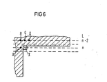
- FIG. 6 shows a section of a television picture using television field transmission.
- the pixels A to D and X of a television field of television lines L n-2 and n are shown.
- the calculation of the estimated value is therefore carried out with the aid of the image signal values A, B, C and D surrounding the current image signal value X, which correspond to the sample values. It is assumed that the luminance signal is to be encoded and transmitted here. The same applies analogously to color difference signals.
- the hatched area in which the image signal values A to D lie corresponds to the image signal value zero, that is to say black, and the next image signal value X corresponds to the maximum image signal value, here the numerical value 255, that is to say white.
- the following estimated value ⁇ is determined from the image signal values X r , C " D r and Er.
- the quantizer is controlled by forming the differences between the reconstructed image signal values A t to D,.
- the maximum difference DS determines the quantization characteristic QK1 to QK4 to be used.
- the following table shows the ranges of 4 different quantization characteristics QK1 to QK4 and their assignment to the different differences DS.
- An additional quantization characteristic QK5 can be useful when transmitting correction values.
- Estimated value X 'and the following image signal value X reach the maximum of 255.
- the difference between that "Incorrectly coded" transmitted DPCM value of size 55 and the correct DPCM value of 255 naturally cause visible disturbances in corners in picture templates.
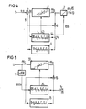
- FIG. 1 shows the basic circuit diagram of a DPCM encoder for implementing the method according to the invention.
- Digitized sample values (luminance or chrominance values), here referred to as image signal values s, are supplied to the code input 1.
- the code input is connected to the first input of a subtractor 2, the output of which is connected to the input of a controllable quantizer 3.
- the output of the quantizer 3 is connected via a first adder 6 and a first switch 8 to an input 41 of a quantizer control logic 4 and the input of a predictor 5.
- the output of the predictor 5 is connected to the second input of the adder 6 and to the subtraction input of the subtractor 2.
- Another input 42 of the quantizer control logic is connected to the output of the subtractor 2.
- a first control output 43 of the quantizer control logic is connected to a control input 31 of the quantizer 3.
- a encoder 7 is connected to the output of the quantizer, the output of which is connected to the first input of a second changeover switch 9.
- the second input of this switch like the second input of the first switch 8, is directly connected to the code input 1.
- the output of the second switch 9 forms the output 10 of the encoder.
- the two changeover switches 8 and 9 are actuated via a second control output 44 of the quantizer control logic 4. This control input also intervenes in the encoder 7.
- the encoder shown works in the usual way.
- the estimate 9 is determined, this is subtracted from the current image signal value s in the subtractor 2 and the DPCM value As is fed to the quantizer 3, the quantization characteristic of which is determined by the quantization control logic 4.
- the quantized DPCM values ⁇ s q present at the output of the quantizer 3 are fed to the encoder 7, which assigns a binary combination to each quantization stage for data reduction. If, for example, 15-stage quantization characteristics QK1 to QK4 are used, the binary combination 0000 to 1110 is used.
- the decoder input 11 is connected to a decoding device 37, a detection circuit 12 and a second input of a changeover switch 19.
- the output of the decoder 37 is connected via a second adder 16 to the first input of the switch 19, the output of which is connected to the input of a decoder control logic 14 corresponding to the quantizer control logic and a predictor 15 at the receiving end.
- the output of the predictor 15 on the receiving side is connected to the second input of the second adder 16.
- the control output of the detection circuit 12 is connected to the control input of the switch 19.
- the image signal values s r are reconstructed in the usual way from the DPCM values ⁇ s c applied to the decoder input 11.
- the decoding device 37 corresponds to the counterpart on the receiving side for the series connection of the controllable quantizer 3 and encoder 7. From the coded DPCM values ⁇ s c , the quantized DPCM values ⁇ s q with the required word width are recovered. If the detection circuit 12 notices the receipt of an identification word KW, the changeover switch 19 is actuated by the received correction signal EKS and the subsequent PCM image signal value s is switched through to the decoder output 20 and thus simultaneously to the decoder control logic 14 and the predictor 15 on the reception side.
- the insertion of the correction signal KS consisting of the code word KW and the PCM image signal value s, causes an irregular data flow.
- the clock control of the decoder control logic and the receiving-side predictor is changed during the reception of a correction signal.
- both the decoder control logic and the receiver-side predictor are supplied with the PCM image signal value transmitted in the correction signal.
- a continuous data flow is again achieved by means of an elastic memory.
- a clock control on the receiving side ensures correct processing.
- a further changeover switch 18 is connected upstream of the input of the controllable quantizer 3, via which the quantizer input can be connected directly to the code input 1 or, as usual, to the output of the subtractor 2.
- the second switch 9 is omitted and, in contrast to the DPCM encoder according to FIG. 1, the second input of the first switch 8 is connected to the output of the quantizer 3 instead of to the code input 1.
- the further changeover switch 18, like the first changeover switch 8, is actuated by the quantizer control logic 4.
- the DPCM decoder corresponding to FIG. 3 differs from the DPCM decoder shown in FIG. 2 only in that the second input of the third switch 19 is connected to the output of the decoding device 37.
- the DPCM coder shown in FIG. 4 differs from the DPCM coder shown in FIG. 3 solely in the absence of the changeover switches 18 and 8.
- the image signal values s r are fed to the quantizer control logic 4.
- Control outputs 43, 44 of the quantizer control logic lead to the controllable quantizer 3 and the encoder 7.
- the identification word is first inserted via the encoder 7. Subsequently, however, a DPCM value is sent out instead of the existing PCM image signal value. Since the transmission of DPCM values of the extent of the finest quantization characteristic (possibly several quantization characteristics) can also be dispensed with here, it is possible to use larger QC5 values (or further quantization characteristics) than otherwise possible using an additional quantization characteristic QK5. to transmit with sufficient quantization accuracy. As usual, the encoder assigns binary combinations to the different stages of the additional quantization characteristic QK5.
- the DPCM decoder shown in FIG. 5 differs from the DPCM decoder shown in FIG. 2 in that there is no switch 19; the inputs of the quantization control logic 14 on the receiving side and of the predictor 15 are directly connected to the output of the adder 16.
- the output of the detection circuit 12 is likewise connected to the decoder control logic 14 and, after receiving an identification word, switches off to the roughest of the usual or to an additional quantization characteristic.
- Another variant of this method consists in delaying the image signal values output at the decoder output and replacing critical image signal values with a correction value which is obtained from adjacent image signal values received later, e.g. is determined from a subsequent image signal value and from the corresponding image signal values of the following image line.
Abstract
Description
Die Erfindung betrifft ein Verfahren zur Verbesserung der Bildqualität, bei dem digitalisierte Bildsignalwerte unter Verwendung einer mehrdimensionalen, insbesondere einer zweidimensionalen Prädiktion und von umschaltbaren Quantisierungskennlinien in quantisierte DPCM-Werte umgesetzt werden.The invention relates to a method for improving the image quality, in which digitized image signal values are converted into quantized DPCM values using a multidimensional, in particular a two-dimensional, prediction and switchable quantization characteristics.
Zur Übertragung von Bildsignalen wird zur Verringerung der Übertragungsrate häufig die Differenzpulscodemodulation (DPCM) eingesetzt. Am gebräuchlichsten ist hierbei die zweidimensionale DPCM, bei der ein Schätz-oder Prädiktionswert aus Bildsignalwerten errechnet wird, die an den aktuellen zu verarbeitenden Bildsignalwert angrenzen. Eine DPCM-Codierung mit zweidimensionaler Prädiktion ist bereits erstaunlich leistungsfähig. Um Flächenrauschen (granular noise) und Überschwingen (slope overload) zu vermeiden, wird zwi-- schen mehreren Quantisierungskenniinien umgeschaltet, so daß die Quantisierung bei kleinen Differenzen zwischen Schätzwert und aktuellen Bildsignalwert in kleinen Quantisierungsstufen erfolgt; bei großen Differenzen, wie sie an Kanten auftreten, wird einen gröbere Quantisierung verwendet, wobei jedoch der Quantisierungsfehler aufgrund des Verdekkungseffektes für das menschliche Auge weitgehend unsichtbar-ist. Obwohl die zweidimensionale Quantisierung -auch bei Kanten -erstaunliches leistet, so ergeben sich doch bei geometrischen Flächen, wie sie beispielsweise bei Gebäuden oder bei Schriftvorlagen häufig anzutreffen sind, an den Ecken deutlich sichtbare Bildfehler.Differential pulse code modulation (DPCM) is often used to reduce the transmission rate when transmitting image signals. The most common is the two-dimensional DPCM, in which an estimate or prediction value is calculated from image signal values that adjoin the current image signal value to be processed. DPCM coding with two-dimensional prediction is already surprisingly powerful. In order to avoid surface noise (granular noise) and overshoot (slope overload), a switch is made between several quantization characteristics, so that the quantization takes place in small quantization steps when there are small differences between the estimated value and the current image signal value; for large differences, such as those occurring at edges, a coarser quantization is used, but the quantization error is largely invisible to the human eye due to the covering effect. Although the two-dimensional quantization - also for edges - does astonishing things, there are clearly visible image defects at the corners of geometric surfaces, such as those often found in buildings or typefaces.
Diese können zwar durch eine dreidimensionale Prädiktion mit dem hierbei erforderlichen hohen Speicheraufwand verringert werden, bleiben jedoch weiterhin störend.Although these can be reduced by a three-dimensional prediction with the high amount of memory required, they still remain disruptive.
Aufgabe der Erfindung ist es, die Bildqualtiät bei zweidimensionaler DPCM-Codierung zu verbessern.The object of the invention is to improve the image quality with two-dimensional DPCM coding.
Ausgehend vom eingangs angegebenen Verfahren wird die Aufgabe dadurch gelöst, daß beim Überschreiten der Maximalwerte einer Quantisierungskennlinie durch den aktuellen DPCM-Wert ein Korrektursignal übertragen wird und sowohl sendeseitig als auch empfangsseitig der nächste rekonstruierte Bildsignalwert mit Hilfe desselben Korrekturwertes ermittelt wird.Starting from the method specified at the outset, the object is achieved in that when the maximum values of a quantization characteristic are exceeded by the current DPCM value, a correction signal is transmitted and the next reconstructed image signal value is determined both on the transmission side and on the reception side with the aid of the same correction value.
Die Erfindung beruht auf der Erkenntnis, daß Bildfehler durch die Verwendung der ungeeigneten Quantisierungskenniinie hervorgerufen werden. Das Umschaltkriterium für den sendeseitigen Quantisierer und für die entsprechende empfangsseitige Decodiereinrichtung kann jeweils nur mit Hilfe der rekonstruierten Bildsignalwerte- erfolgen, da der Gleichlauf zwischen Coder und Decoder nicht gestört werden darf. Dem Decoder ist naturgemäß ein Blick in die Zukunft versagt, der Coder, der ja dieselbe Steuerlogik verwendet jedoch eine Fehlsteuerung des Quantisierers rechtzeitig bemerkt, korrigiert seinen Fehler und teilt dieses durch das Korrektursignal auch dem Decoder mit, in dessen Rechenschleife derselbe Korrekturwert eingespeist wird. Durch diese Prozedur treten kritische Bildsignalfehler an Kanten nicht mehr störend in Erscheinung und der Gleichlauf zwischen Coder und Decoder wird nicht gestört.The invention is based on the knowledge that image errors are caused by the use of the unsuitable quantization characteristic. The switchover criterion for the transmitter-side quantizer and for the corresponding receiver-side decoding device can only take place with the aid of the reconstructed image signal values, since the synchronism between the encoder and decoder must not be disturbed. The decoder naturally fails to take a look into the future, the coder, which uses the same control logic but notices incorrect control of the quantizer in good time, corrects its error and communicates this to the decoder via the correction signal, the same correction value being fed into the calculation loop. This procedure means that critical image signal errors on edges no longer appear to be disturbing and the synchronism between encoder and decoder is not disturbed.
Es ist vorteilhaft, daß als Korrektursignal ein Kennwort und ein PCM-Korrekturwert übertragen werden und außerdem zweckmäßig daß der PCM-Korrekturwert quantisiert übertragen wird.It is advantageous that a password and a PCM correction value are transmitted as the correction signal, and it is also expedient that the PCM correction value is transmitted quantized.
An Stelle eines verfälschten DPCM-Wertes wird der entsprechende PCM-Bildsignalwert übertragen und sowohl sende-als auch empfangsseitig zur Berechnung der weiteren Schätzwerte verwendet. Es ist hierbei ausreichend, daß dieser PCM-Wert ebenfalls quantisiert übertragen wird.Instead of a falsified DPCM value, the corresponding PCM image signal value is transmitted and used for the calculation of the further estimated values both on the transmission side and on the reception side. It is sufficient that this PCM value is also transmitted quantized.
Es ist ebenfalls vorteilhaft, daß als Korrektursignal ein Kennwort zur Umschaltung der Quantisierungskennlinie auf eine gröbere Quantisierungskennlinie mit größerem Quantisierungsbereich und ein entsprechend dieser Quantisierungskennlinie quantisierter PCM-Korrekturwert übertragen wird.It is also advantageous that a password for switching the quantization characteristic to a coarser quantization characteristic with a larger quantization range and a PCM correction value quantized in accordance with this quantization characteristic is transmitted as the correction signal.
Es ist für die meisten Anwendungsfälle ausreichend und benötigt nur einen minimalen zusätzlichen Aufwand, wenn das Korrektursignal nur zur Umschaltung auf die richtige Quantisierungskennlinie verwendet wird. Bei hohen Kontrasten bleibt zwar ein Restfehler übrig, jedoch ergibt sich eine deutliche Verbesserung der BildqualitätIt is sufficient for most applications and requires minimal additional effort if the correction signal is only used to switch to the correct quantization curve. At high contrasts, a residual error remains, but there is a significant improvement in the image quality
Es ist zweckmäßig, daß stets auf die gröbste Quantisierungskennlinie umgeschaltet wird.It is advisable to always switch to the coarsest quantization curve.
Da bei großen DPCM-Werten der Quantisierungsfehler nicht sonderlich kritisch ist, wird auf die gröbste Quantisierungskennlinie umgeschaltet Entsprechend den verwendeten Quantisierungskennlinien kann diese Umschaltung auch von der feinsten Quanfisierungskennlinie oder den beiden feinsten Quantisierungskennlinien auf die gröbste beschränkt werden.Since the quantization error is not particularly critical in the case of large DPCM values, the system switches over to the coarsest quantization characteristic. Depending on the quantization characteristics used, this switchover can also be limited to the coarsest from the finest quantization characteristic or the two finest quantization characteristics.
Es ist vorteilhaft, daß stets auf eine zusätzliche Quantisierungskennlinie, deren Bereich erweitert ist und kleine DPCM-Werte nicht mehr umfaßt, umgeschaltet wird.It is advantageous that a switch is always made to an additional quantization characteristic, the range of which is expanded and no longer includes small DPCM values.
Da die Quantisierungsbereiche um Null nicht benötigt werden, ist es möglich, die entsprechenden Binärkombinationen zur Übertragung größerer DPCM-Werte als sonst möglich zu verwenden. Die Übertragung dieser DPCM-Werte erfolgt zweckmäßigerweise direkt nach dem Kennwort.Since the quantization ranges around zero are not required, it is possible to use the corresponding binary combinations to transmit larger DPCM values than is otherwise possible. These DPCM values are expediently transmitted directly after the password.
Es ist zweckmäßig, daß als Kennungswort eine nicht verwendete Binärkombination der codierten DPCM-Werte übertragen wird.It is expedient that an unused binary combination of the coded DPCM values is transmitted as the identification word.
Bei dieser Ausbildung wird die Datenrate nicht erhöht und es werden keine Pufferspeicher benötigt. Bei diesem Verfahren wird annähernd die gleiche Bildverbesserung wie bei einer Umschaltung der Quantisierungskennlinie erzielt.With this design, the data rate is not increased and no buffer memory is required. With this method, approximately the same image improvement is achieved as when the quantization characteristic is switched.
Weitere vorteilhafte Ausbildungen der Erfindung sind in den übrigen Unteransprüchen angegeben.Further advantageous developments of the invention are specified in the remaining subclaims.
Das Verfahren wird anhand von Ausführungsbeispielen näher erläutert.The method is explained in more detail using exemplary embodiments.
Es zeigen
- Fig. 1 das Prinzipschaltbild eines DPCM-Coders,
- Fig. 2 das Prinzipschaltbild eines DPCM-Decoders,
- Fig. 3 eine Variante des DPCM-Coders,
- Fig. 4 das Prinzipschaltbild eines DPCM-Coders zur Korrektur der DPCM-Werte,
- Fig. 5 das Prinzipschaltbild eines zugehörigen DPCM-Decoders und
- Fig. 6 einen Ausschnitt aus einem Fernsehbild.
- 1 shows the basic circuit diagram of a DPCM encoder,
- 2 shows the basic circuit diagram of a DPCM decoder,
- 3 shows a variant of the DPCM coder,
- 4 shows the basic circuit diagram of a DPCM encoder for correcting the DPCM values,
- 5 shows the basic circuit diagram of an associated DPCM decoder and
- Fig. 6 shows a detail from a television picture.
In Fig. 6 ist ein Ausschnitt aus einem Fernsehbild bei Anwendung der Fernsehhalbbildübertragung dargestellt. Es sind die Bildpunkte A bis D und X eines Fernsehhalbbildes von Fernsehzeilen L = n-2 und n dargestellt.![]()
![]()
![]()
![]()
![]()
![]()
![]()
![]()
Bei der in Fig. 6 dargestellten Bildkonfiguration tritt jetzt folgendes Problem auf, das hier für einen speziellen Bildsignalwert X abgehandelt wird. Die Differenzen zwischen den Bildsignalwerten Arbis Dr sind gleich Null. Folglich wird die Quantisierungskennlinie QK1 einaestellt. Es wird der Schätzwert![]()
![]()
ermittelt. Die Differenz zwischen Wegen der rekursiven Struktur des Coders und des Decoders werden statt der ursprünglichen Bildsignalwerte s = A,B,... die rekonstruierten Bildsignalwerte sr = Ar, B r... zur Berechnung des Schätzwertes S verwendet. Hierdurch bleibt auch der Gleichlauf zwischen Coder und Decoder erhalten.determined. The difference between because of the recursive structure of the encoder and the decoder, instead of the original image signal values s = A , B , ... the reconstructed image signal values s r = A r , B r ... are used to calculate the estimated value S. This also keeps the encoder and decoder in sync.
Für die Berechnung eines Schätz-oder Prädiktionswertes s = gilt beispielsweise:![]()
![]()
Die Berechnung des Schätzwertes erfolgt also mit Hilfe der den aktuellen Bildsignalwert X umgebenen Bildsignalwerte A, B, C und D, die Abtastwerten entsprechen. Es wird angenommen, daß hier das Luminanzsignal codiert und übertragen werden soll. Für Farbdifferenzsignale gilt das gleiche sinngemäß. Der schraffierte Bereich, in dem die Bildsignalwerte A bis D liegen, entspricht dem Bildsignalwert Null, also schwarz, und der nächste Bildsignalwert X entspricht dem maximalen Bildsignalwert, hier dem, Zahlenwert 255, also weiß. Der folgende Schätzwert ŷ, wird aus den Bildsignalwerten Xr, C " Dr und Er ermittelt.The calculation of the estimated value is therefore carried out with the aid of the image signal values A, B, C and D surrounding the current image signal value X, which correspond to the sample values. It is assumed that the luminance signal is to be encoded and transmitted here. The same applies analogously to color difference signals. The hatched area in which the image signal values A to D lie corresponds to the image signal value zero, that is to say black, and the next image signal value X corresponds to the maximum image signal value, here the numerical value 255, that is to say white. The following estimated value ŷ is determined from the image signal values X r , C " D r and Er.
Die Steuerung des Quantisierers erfolgt durch Bildung der Differenzen der rekonstruierten Bildsignalwerte At bis D,.![]()
![]()
Die maximale Differenz DS bestimmt die zu verwendende Quantisierungskennlinie QK1 bis QK4. In der folgenden Tabelle sind die Bereiche von 4 verschiedenen Quantisierungskennlinien QK1 bis QK4 und ihre Zuordnung zu den verschiedenen Differenzen DS dargestellt. Eine zusätzliche Quantisierungskennlinie QK5 kann bei der Übertragung von Korrekturwerten zweckmäßig sein.![]()
![]()
![]()
![]()

![]()
![]()
![]()
![]()
Schätzwert X' und dem folgenden Bildsignalwert X erreicht das Maximum'von 255. Es kann jedoch entsprechend der Quantisierungskennlinie QK1 nur der maximale DPCM-Wert M1 = t55 übertragen werden. Die Differenz zwischen dem "falsch codierten" ausgesendeten DPCM-Wert der Größe 55 und dem korrekten DPCM-Wert von 255 bewirkt bei Ecken in Bildvorlagen natürlich sichtbare Störungen.Estimated value X 'and the following image signal value X reach the maximum of 255. However, according to the quantization characteristic QK1, only the maximum DPCM value M1 = t55 can be transmitted. The difference between that "Incorrectly coded" transmitted DPCM value of size 55 and the correct DPCM value of 255 naturally cause visible disturbances in corners in picture templates.
Da empfangsseitig zur Steuerung einer dem Quantisierer und dem üblicherweise nachgeschalteten Codierer entsprechenden Decodiereinrichtung ebenfalls nur die bereits rekonstruierten Bildsignalwerte Ar bis Dr zur Verfügung stehen wird naturgemäß der nächste Bildsignalwert Xr wie beim DPCM-Coder nach derselben Quantisierungskennlinie falsch rekonstruiert. Bei allen zu treffenden Maßnahmen ist bekannterweise stets zu berücksichtigen, daß die Prädiktionsschleifen des DPCM-Coders und des DPCM-Decoders stets synchron laufen.Since only the already reconstructed image signal values A r to D r are also available at the receiving end for controlling a decoder corresponding to the quantizer and the encoder connected downstream, the next image signal value X r is naturally incorrectly reconstructed according to the same quantization characteristic as in the DPCM coder. For all measures to be taken, it is known to always take into account that the prediction loops of the DPCM encoder and the DPCM decoder always run synchronously.
In Fig. 1 ist das Prinzipschaltbild eines DPCM-Coders zur Realisierung des erfindungsgemäßen Verfahrens dargestellt. Dem Codereingang 1 werden digitalisierte Abtastwerte (Luminanz-oder Chrominanzwerte), hier als Bildsignalwerte s bezeichnet, zugeführt. Der Codereingang ist mit dem ersten Eingang eines Subtrahierers 2 verbunden, dessen Ausgang mit dem Eingang eines steuerbaren Quantisierers 3 verbunden ist. Der Ausgang des Quantisierers 3 ist über einen ersten Addierer 6 und einen ersten Umschalter 8 mit einem Eingang 41 einer Quantisierersteuerlogik 4 und dem Eingang eines Prädiktors 5 verbunden. Der Ausgang des Prädiktors 5 ist mit dem zweiten Eingang des Addierers 6 und mit dem Subtraktionseingang des Subtrahierers 2 verbunden. Ein weiterer Eingang 42 der Quantisierersteuerlogik ist mit dem Ausgang des Subtrahierers 2 verbunden. Ein erster Steuerausgang 43 der Quantisierersteuerlogik ist mit einem Steuereingang 31 des Quantisierers 3 verbunden. An den Ausgang des Quantisierers ist ein Codierer 7 angeschaltet, dessen Ausgang mit dem ersten Eingang eines zweiten Umschalters 9 verbunden ist. Der zweite Eingang dieses Umschalters ist ebenso wie der zweite Eingang des ersten Umschalters 8 direkt mit dem Codereingang 1 verbunden. Der Ausgang des zweiten Umschalters 9 bildet den Ausgang 10 des Coders. Die beiden Umschalter 8 und 9 werden über einen zweiten Steuerausgang 44 der Quantisierersteuerlogik 4 betätigt. Dieser Steuereingang greift auch in den Codierer 7 ein.1 shows the basic circuit diagram of a DPCM encoder for implementing the method according to the invention. Digitized sample values (luminance or chrominance values), here referred to as image signal values s, are supplied to the code input 1. The code input is connected to the first input of a
Befinden sich die beiden Umschalter 8 und 9 in der dargestellten Lage, so arbeitet der dargestellte Coder in der üblichen Weise. In dem Prädiktor 5 wird der Schätzwert 9 ermittelt, dieser wird im Subtrahierer 2 von dem aktuellen Bildsignalwert s abgezogen und der DPCM-Wert As wird dem Quantisierer 3 zugeführt, dessen Quantisierungskennlinie von der Quantisierungssteuerlogik 4 bestimmt wird. Die am Ausgang des Quantisierers 3 anliegenden quantisierten DPCM-Werte Δsq werden dem Codierer 7 zugeführt, der zur Datenreduktion jeder Quantisierungsstüfe eine Binärkombination zuordnet. Werden beispielsweise 15stufige Quanfisierungskennlinien QK1 bis QK4 verwendet, so werden die Binärkombination 0000 bis 1110 verwendet.If the two
Tritt nun der einleitend geschilderte Fall einer notwendigen Korrektur der DPCM-Werte ein, bei dem der DPCM-Wert δ größer ist als der maximal bei der eingestellten Quantisierungskennlinie, z.B. QK1, übertragbare DPCM-Wert, so wird durch die Quantisierersteuerlogik 4 durch Abgabe eines Korrektursteuersignals KSS zunächst der Codierer 7 veranlaßt ein Korrektursignal KS auszusenden, zunächst ein Kennungswort KW = 1111, das hier einer nicht verwendeten Binärkombination des Codierers 7 entspricht Anschließend werden beide Umschalter 8 und 9 betätigt und der entsprechende Bildsignalwert s (bzw. X nach Fig. 6) übertragen und gleichzeitig -wie ein rekonstruierter Bildsignalwert sr -in den Prädiktor 5 übernommen.If the above-described case of a necessary correction of the DPCM values occurs, in which the DPCM value δ is greater than the maximum DPCM value that can be transmitted at the set quantization characteristic, e.g. QK1, the quantizer control logic 4 outputs a correction control signal KSS first of all the encoder 7 causes a correction signal KS to be sent out, first an identification word KW = 1111, which corresponds here to an unused binary combination of the encoder 7. Then both
Bei diesen Verfahren ist es also notwendig, ein zusätzliches Kennungswort und ein eventuell längeres DPCM-Wort zu übertragen. Deshalb sind elastische Speicher notwendig. Dies gilt natürlich auch bei Anwendung einer Optimalcodierung. Die Taktversorgung dieser Speicher erfolgt zweckmäßigerweise über Phasenregelkreise.With these methods, it is therefore necessary to transmit an additional identification word and a possibly longer DPCM word. Therefore elastic storage is necessary. Of course, this also applies when using optimal coding. The clock supply of these memories is expediently carried out via phase locked loops.
In Fig. 2 ist das Prinzipschaltbild des zugehörigen DPCM-Decoders dargestellt. Der Decodereingang 11 ist mit einer Decodiereinrichtung 37, einer Erkennungsschaltung 12 und einem zweiten Eingang eines Umschalters 19 verbunden. Der Ausgang der Decodiereinrichtung 37 ist über einen zweiten Addierer 16 mit dem ersten Eingang des Umschalters 19 verbunden, dessen Ausgang mit dem Eingang einer der Quantisierersteuerlogik entsprechenden Decodierersteuerlogik 14 und einem empfangsseitigen Prädiktor 15 verbunden ist. Der Ausgang des empfangsseitigen Prädiktors 15 ist mit dem zweiten Eingang des zweiten Addierers 16 verbunden. Der Steuerausgang der Erkennungsschaltung 12 ist mit dem Steuereingang des Umschalters 19 verbunden.2 shows the basic circuit diagram of the associated DPCM decoder. The decoder input 11 is connected to a
Der Ausgang des Umschalters 19 bildet den Ausgang 20 des Decoders, an dem die rekonstruierten Bildsignalwerte sr = Ar, Br, Cr,... abgegeben werden.The output of the
In der gezeichneten Stellung des Umschaiters 19 werden in der üblichen Weise aus den am Decodereingang 11 anliegenden DPCM-Werten Δsc die Bildsignalwerte sr rekonstruiert. Die Decodiereinrichtung 37 entspricht hierbei dem empfangsseitigen Gegenstück zur Reihenschaltung des steuerbaren Quantisierers 3 und des Codierers 7. Aus den codierten DPCM-Werten Δsc werden die quantisierten DPCM-Werte Δsq mit der benötigten Wortbreite wiedergewonnen. Bemerkt die Erkennungsschaltung 12 den Empfang eines Kennungswortes KW, so wird der Umschalter 19 durch das empfangene Korrektursignal EKS betätigt und der nachfolgende PCM-Bildsignalwert s an den Decoderausgang 20 und damit gleichzeitig an die Decodierersteuerlogik 14 und dem empfangsseitigen Prädiktor 15 durchgeschaltet.In the drawn position of the
Das Einfügen des aus Kennungswort KW und PCM-Bildsignalwert s bestehenden Korrektursignals KS bewirkt einen unregelmäßigen Datenfluß. Selbstverständlich wird während des Empfangs eines Korrektursignals die Taktsteuerung der Decodierersteuerlogik und des empfangsseitigen Prädiktors geändert.The insertion of the correction signal KS, consisting of the code word KW and the PCM image signal value s, causes an irregular data flow. Of course, the clock control of the decoder control logic and the receiving-side predictor is changed during the reception of a correction signal.
An Stelle eines rekonstruierten Bildsigalwertes s, wird sowohl der Decodierersteuerlogik als auch dem empfangsseitigen Prädiktor der im Korrektursignal übertragener PCM-Bildsignalwert zugeführt. Ein kontinuierlicher Datenfluß wird wieder durch einen elastischen Speicher erreicht. Eine empfangsseitige Taktsteuerung sorgt für die korrekte Verarbeitung.Instead of a reconstructed image signal value s, both the decoder control logic and the receiver-side predictor are supplied with the PCM image signal value transmitted in the correction signal. A continuous data flow is again achieved by means of an elastic memory. A clock control on the receiving side ensures correct processing.
In Fig. 3 ist eine Variante des DPCM-Coders dargestellt. Dem Eingang des steuerbaren Quantisierers 3 ist ein weiterer Umschalter 18 vorgeschaltet, über den der Quantisierereingang direkt an den Codereingang 1 oder -wie üblich -an den Ausgang des Subtrahierers 2 angeschaltet werden kann. Der zweite Umschalter 9 entfällt und im Gegensatz zum DPCM-Codierer nach Fig. 1 ist der zweite Eingang des ersten Umschalters 8 statt mit dem Codereingang 1 an den Ausgang des Quantisierers 3 angeschaltet. Der weitere Umschalter 18 wird wie auch der erste Umschalter 8 von der Quantisierersteuerlogik 4 betätigt.3 shows a variant of the DPCM coder. A
Bei diesem DPCM-Coder werden bei einer erforderlichen Korrektur die Bildsignalwerte s ebenfalls dem Quantisierer 3 zugeführt um als quantisierte Bildsignalwerte sq in den Prädiktor 5 eingegeben und codiert ausgesendet zu werden. Da nur bei großen Beträgen der DPCM-Werte s eine direkte Übertragung der quantisierten Bildsignalwerte sq notwendig ist, kann der Quantisierungsbereich erweitert werden, da kleine Wertebereiche = | ± 55 nicht übertragen werden müssen. So ist es beispielsweise möglich, statt eines maximalen DPCM-Wertes von ± ± 120 quantisierte Bildsignalwerte zwischen 56 und 255 zu übertragen.In the case of this DPCM coder, if a correction is required, the image signal values s are also fed to the
Der Fig. 3 entsprechende DPCM-Decoder unterscheidet sich vom in Fig. 2 dargestellten DPCM-Decoder lediglich darin, daß der zweite Eingang des dritten Umschalters 19 an den Ausgang der Decodiereinrichtung 37 angeschaltet ist.The DPCM decoder corresponding to FIG. 3 differs from the DPCM decoder shown in FIG. 2 only in that the second input of the
Der in Fig. 4 dargestellte DPCM-Coder unterscheidet sich von dem in Fig. 3 dargestellten DPCM-Coder allein durch das Fehlen der Umschalter 18 und 8. Der Quantisierersteuerlogik 4 werden die Bildsignalwerte sr zugeführt. Steuerausgänge 43, 44 der Quantisierersteuerlogik führen zum steuerbaren Quantisierer 3 und zum Codierer 7.The DPCM coder shown in FIG. 4 differs from the DPCM coder shown in FIG. 3 solely in the absence of the changeover switches 18 and 8. The image signal values s r are fed to the quantizer control logic 4. Control outputs 43, 44 of the quantizer control logic lead to the
Mit dieser Schaltungsanordnung wird wie bisher -wenn eine Umschaltung der Quantisierungskennlinie aufgrund eines betragsmäßig großen DPCM-Wertes As erforderlich ist -zunächst über den Codierer 7 das Kennungswort eingefügt. Anschließend wird jedoch statt des anliegenden PCM-Bildsignalwertes ein DPCM-Wert ausgesendet. Da hier ebenfalls auf die Übertragung von DPCM-Werten des Umfanges der feinsten Quantisierungskennlinie (gegebenenfalls mehrerer Quantisierungskennlinien) verzichtet werden kann, ist es möglich, unter Verwendung einer zusätzlichen Quantisierungskennlinie QK5 (oder weiterer Quantisierungskennlinien) größere DPCM-Werte als sonst möglich . mit ausreichender Quantisierungsgenauigkeit zu übertragen. Den verschiedenen Stufen der zusätzlichen Quantisierungskennlinie QK5 werden wie üblich vom Codierer Binärkombinationen zugeordnet.With this circuit arrangement, as before, if a changeover of the quantization characteristic is necessary due to a large DPCM value As, the identification word is first inserted via the encoder 7. Subsequently, however, a DPCM value is sent out instead of the existing PCM image signal value. Since the transmission of DPCM values of the extent of the finest quantization characteristic (possibly several quantization characteristics) can also be dispensed with here, it is possible to use larger QC5 values (or further quantization characteristics) than otherwise possible using an additional quantization characteristic QK5. to transmit with sufficient quantization accuracy. As usual, the encoder assigns binary combinations to the different stages of the additional quantization characteristic QK5.
Der in Fig. 5 dargestellte DPCM-Decoder unterscheidet sich von dem in Fig. 2 dargestellten DPCM-Decoder durch das Fehlen eines Umschalters 19; an den Ausgang des Addierers 16 sind die Eingänge der empfangsseitigen Quantisierungssteuerlogik 14 und des Prädiktors 15 direkt angeschaltet. Der Ausgang der Erkennungsschaltung 12 ist ebenfalls mit der Decodierersteuerlogik 14 verbunden und schaltet nach Empfang eines Kennungswortes auf die gröbste der üblichen oder auf eine zusätzliche Quantisierungskennlinie aus.The DPCM decoder shown in FIG. 5 differs from the DPCM decoder shown in FIG. 2 in that there is no
Durch das Einfügen des Kennungswortes sind wiederum elastische Speicher erforderlich, auf deren Darstellung auch hier verzichtet wurde.By inserting the identification word, elastic memories are again required, which are not shown here either.
Eine Variante besteht darin, daß erst bei Überschreitung eines Schwellwertes S1 = 80 durch den DPCM-Wert As bei eingeschalteter feinster Quantisierungskennlinie QK1 ein Kennungswort an Stelle des "fehlerhaft" codierten DPCM-Wertes übertragen wird. Empfangsseitig bewirkt dies über die Decodierersteuerlogik 14, daß von der Decodiereinrichtung 37 ein konstanter DPCM-Wert abgegeben wird, der etwa dem Maximalwert (|± 1-201) der gröbsten Quantisierungskennlinie QK4 entspricht. Wird als Kennungswort eine nicht zu Quantisierungszwecken benutzte Binärkombination vom Codierer 7 abgegeben, so ist keinerlei Geschwindungsänderung erforderlich. Steht nur eine einzige Binärkombination zur Verfügung, so wird das notwendige Vorzeichen des konstanten DPCM-Wertes aus den vorherigen rekonstruierten Bildsignalwerten abgeleitet. Ist z.B. der vorherige Bildsignalwert betragsmäßig größer als ein zweiter Stellwert, beispielsweise S2 = 128, so ist das Vorzeichen des Kennungswertes dem des letzten Bildsignalwertes entgegengesetzt übertragen. Diese Variante liefert natürlich keine optimalen Ergebnisse, bewirkt aber trotz des minimalen Aufwandes eine deutliche Verbesserung der Bildqualität.A variant consists in that an identification word instead of the "incorrectly" coded DPCM value is only transmitted when a threshold value S1 = 80 is exceeded by the DPCM value As with the finest quantization characteristic QK1 switched on. At the receiving end, this causes, via the
Eine weitere Variante dieses Verfahrens besteht darin, die am Decoderausgang abgegebenen Bildsignalwerte zu verzögern und kritische Bildsignalwerte durch einen Korrekturwert zu ersetzen, der aus später empfangenen angrenzenden Bildsignalwerten, z.B. aus einem nachfolgenden Bildsignalwert und aus den entsprechenden Bildsignalwerten der folgenden Bildzeile, ermittelt wird.Another variant of this method consists in delaying the image signal values output at the decoder output and replacing critical image signal values with a correction value which is obtained from adjacent image signal values received later, e.g. is determined from a subsequent image signal value and from the corresponding image signal values of the following image line.
- 1 Codereingang1 code input
- 2 Subtrahierer2 subtractors
- 3 Quantisierer3 quantizers
- 4 Quantisierersteuerlogik4 quantizer control logic
- 5 Prädiktor5 predictor
- 6 Addierer6 adders
- 7 Codierer7 encoders
- 8 Umschalter8 switches
- 9 zweiter Umschalten9 second switchover
- 10 Ausgang des Coders10 Output of the encoder
- 31 Steuereingang31 control input
- 41 Eingang der Quantisierersteuerlogik 441 Input of quantizer control logic 4
- 42 weiterer Eingang42 further entrance
- 43 erster Steuerausgang43 first control output
- 44 zweiter Steuerausgang44 second control output
- s Bildisignalwerts image signal value
- ŷ Schätzwertŷ estimate
- SchätzwertEstimate
- Δ sq quantisierter DPCM-WertΔ sq quantized DPCM value
- A sc codierter DPCM-WertA s c encoded DPCM value
- KW KennungswortKW password
- KSS KorrektursteuersignalKSS correction control signal
- A s DPCM-WertA s DPCM value
- Xr,Sr rekonstruierter BildsignalwertX r , S r reconstructed image signal value
- Sq quantisierter BildsignalwertSq quantized image signal value
- 11 Decodereingang11 decoder input
- 12 Erkennungsschaltung12 detection circuit
- 14 Decodersteuerlogik14 decoder control logic
- 15 Prädiktor15 predictor
- 16 Addierer16 adders
- 19 Umschalter19 switches
- 20 Ausgang des Decoders20 output of the decoder
- 37 Decodiereinrichtung37 decoder
- EKS emfangenes KorrektursignalEKS received correction signal
- 18 Umschalter18 switches
- PK PCM-KorrekturwertPK PCM correction value
- DK quantisierter PMC-KorrekturwertDK quantized PMC correction value
- KS KorrektursignalKS correction signal
- QK1 QuantisierungskennlinieQK1 quantization characteristic
- M1 MaximalwertM1 maximum value
- KD konstanter KorrekturwertKD constant correction value
- L FemsehzeileL TV line
- S1 SchwellwertS1 threshold
- DS größte DifferenzDS biggest difference
Claims (10)
Applications Claiming Priority (2)
| Application Number | Priority Date | Filing Date | Title |
|---|---|---|---|
| DE19853511660 DE3511660A1 (en) | 1985-03-29 | 1985-03-29 | METHOD FOR IMPROVING IMAGE QUALITY FOR DPCM-CODED IMAGE SIGNALS |
| DE3511660 | 1985-03-29 |
Publications (1)
| Publication Number | Publication Date |
|---|---|
| EP0197446A1 true EP0197446A1 (en) | 1986-10-15 |
Family
ID=6266851
Family Applications (1)
| Application Number | Title | Priority Date | Filing Date |
|---|---|---|---|
| EP86104212A Withdrawn EP0197446A1 (en) | 1985-03-29 | 1986-03-26 | Method for improving the picture quality of DPCM-coded picture signals |
Country Status (2)
| Country | Link |
|---|---|
| EP (1) | EP0197446A1 (en) |
| DE (1) | DE3511660A1 (en) |
Cited By (4)
| Publication number | Priority date | Publication date | Assignee | Title |
|---|---|---|---|---|
| EP0414193A2 (en) * | 1989-08-21 | 1991-02-27 | Mitsubishi Denki Kabushiki Kaisha | Adaptive quantization coder/decoder |
| EP0444839A2 (en) * | 1990-02-26 | 1991-09-04 | Sony Corporation | Video signal transmission system and method and apparatus for coding a video signal |
| EP0547826A1 (en) * | 1991-12-18 | 1993-06-23 | Raytheon Company | B-adaptive ADPCM image data compressor |
| US6109665A (en) * | 1995-12-21 | 2000-08-29 | Metu-System Meining Kg | Butt joint of air duct sections |
Families Citing this family (3)
| Publication number | Priority date | Publication date | Assignee | Title |
|---|---|---|---|---|
| DE3812665A1 (en) * | 1988-04-15 | 1989-10-26 | Siemens Ag | Method for transmitting video signals |
| JP2892783B2 (en) * | 1990-07-09 | 1999-05-17 | 松下電器産業株式会社 | Video signal encoding device |
| JPH0474063A (en) * | 1990-07-13 | 1992-03-09 | Matsushita Electric Ind Co Ltd | Coding method for picture |
Citations (4)
| Publication number | Priority date | Publication date | Assignee | Title |
|---|---|---|---|---|
| US3403226A (en) * | 1965-09-30 | 1968-09-24 | Bell Telephone Labor Inc | Reduced bandwidth dual mode encoding of video signals |
| US3422227A (en) * | 1965-09-30 | 1969-01-14 | Bell Telephone Labor Inc | Dual code differential encoding scheme for video signals |
| US3761613A (en) * | 1972-06-20 | 1973-09-25 | Bell Telephone Labor Inc | Dual mode video encoder |
| US4217609A (en) * | 1978-02-28 | 1980-08-12 | Kokusai Denshin Denwa Kabushiki Kaisha | Adaptive predictive coding system for television signals |
-
1985
- 1985-03-29 DE DE19853511660 patent/DE3511660A1/en not_active Withdrawn
-
1986
- 1986-03-26 EP EP86104212A patent/EP0197446A1/en not_active Withdrawn
Patent Citations (4)
| Publication number | Priority date | Publication date | Assignee | Title |
|---|---|---|---|---|
| US3403226A (en) * | 1965-09-30 | 1968-09-24 | Bell Telephone Labor Inc | Reduced bandwidth dual mode encoding of video signals |
| US3422227A (en) * | 1965-09-30 | 1969-01-14 | Bell Telephone Labor Inc | Dual code differential encoding scheme for video signals |
| US3761613A (en) * | 1972-06-20 | 1973-09-25 | Bell Telephone Labor Inc | Dual mode video encoder |
| US4217609A (en) * | 1978-02-28 | 1980-08-12 | Kokusai Denshin Denwa Kabushiki Kaisha | Adaptive predictive coding system for television signals |
Non-Patent Citations (3)
| Title |
|---|
| FUNKSCHAU, Band 45, Nr. 16, August 1973, Seiten 591-593, München, DE; H. SCHÖNFELDER: "Nachrichtenreduktion für Bildsignale" * |
| IEEE TRANSACTIONS ON COMMUNICATIONS, Band COM-15, Nr. 2, April 1967, Seiten 204-208, IEEE, New York, US; F.K. MANASSE: "Directional correlation - A technique to reduce bandwidth in PCM television transmissions" * |
| RADIO MENTOR ELECTRONIC, Band 38, Nr. 10, Oktober 1972, Seiten 489-490, München, DE; H.-G. GIESE et al.: "Ein Redundanzreduktionsverfahren für digitale Fernsehübertragungen" * |
Cited By (11)
| Publication number | Priority date | Publication date | Assignee | Title |
|---|---|---|---|---|
| EP0414193A2 (en) * | 1989-08-21 | 1991-02-27 | Mitsubishi Denki Kabushiki Kaisha | Adaptive quantization coder/decoder |
| EP0414193A3 (en) * | 1989-08-21 | 1991-12-27 | Mitsubishi Denki Kabushiki Kaisha | Adaptive quantization coder/decoder |
| EP0444839A2 (en) * | 1990-02-26 | 1991-09-04 | Sony Corporation | Video signal transmission system and method and apparatus for coding a video signal |
| EP0444839A3 (en) * | 1990-02-26 | 1994-02-09 | Sony Corp | |
| EP0739142A2 (en) * | 1990-02-26 | 1996-10-23 | Sony Corporation | Video signal coding system and method |
| EP0739143A2 (en) * | 1990-02-26 | 1996-10-23 | Sony Corporation | Video signal coding system and method |
| EP0739143A3 (en) * | 1990-02-26 | 1996-12-18 | Sony Corp | Video signal coding system and method |
| EP0739142A3 (en) * | 1990-02-26 | 1996-12-18 | Sony Corp | Video signal coding system and method |
| KR100248692B1 (en) * | 1990-02-26 | 2000-03-15 | 이데이 노부유끼 | System for coding video signal and method for coding video signal |
| EP0547826A1 (en) * | 1991-12-18 | 1993-06-23 | Raytheon Company | B-adaptive ADPCM image data compressor |
| US6109665A (en) * | 1995-12-21 | 2000-08-29 | Metu-System Meining Kg | Butt joint of air duct sections |
Also Published As
| Publication number | Publication date |
|---|---|
| DE3511660A1 (en) | 1986-10-02 |
Similar Documents
| Publication | Publication Date | Title |
|---|---|---|
| DE3213298C2 (en) | Circuit arrangement for mixing two color video signals by means of color stamping | |
| DE2241457C3 (en) | Method for the digital coding of an analog signal | |
| DE4242796A1 (en) | High efficiency coding of two level mixed natural images for image transmission - identifying input signals and digitising before image synthesis and coding processing into final form | |
| DE3331426A1 (en) | ARRANGEMENT FOR TWO-DIMENSIONAL DPCM CODING | |
| DE2740945A1 (en) | METHOD FOR TRANSMITTING IMAGE SIGNALS USING DIFFERENTIAL PULS CODE MODULATION (DPCM) AND CONTROLLED QUANTIZER | |
| EP0123893B1 (en) | Method and circuit for picture error correction | |
| DE3319438C2 (en) | ||
| DE3426939C2 (en) | Apparatus for closed predictive quantization of a digital vector signal | |
| EP0773690A2 (en) | Method for encoding a video data stream | |
| DE19717608B4 (en) | Perception error handling method and picture coding apparatus using this method | |
| EP0197446A1 (en) | Method for improving the picture quality of DPCM-coded picture signals | |
| EP0271547B1 (en) | System for noise reduction | |
| EP0346637B1 (en) | Method for processing and transmitting a picture sequence | |
| DE19652362A1 (en) | Method and device for compensating for the luminance defects resulting from the processing of chrominance signals | |
| DE2701649C2 (en) | Method for the digital transmission of the luminance signal of a separately coded color video signal | |
| DE19643907B4 (en) | Method and apparatus for moving picture coding | |
| DE2703854C2 (en) | Image transmission system | |
| DE3311898C2 (en) | Method for reducing interference signals from digital data-reduced television signals | |
| DE3726601C2 (en) | ||
| EP0244001A2 (en) | Hybrid coder for videosignals | |
| DE2454232C2 (en) | System for coding video signals using the so-called difference signal method | |
| DE2364629A1 (en) | SYSTEM FOR CODING VIDEO SIGNALS ACCORDING TO THE SO-CALLED DIFFERENTIAL SIGNAL PROCEDURE | |
| EP0346636A2 (en) | Method for processing and transmitting a picture sequence | |
| DE3414982A1 (en) | Method for the digital transmission of image signals | |
| EP0197453B1 (en) | Method for improving the picture quality of dpcm-coded picture signals |
Legal Events
| Date | Code | Title | Description |
|---|---|---|---|
| PUAI | Public reference made under article 153(3) epc to a published international application that has entered the european phase |
Free format text: ORIGINAL CODE: 0009012 |
|
| AK | Designated contracting states |
Kind code of ref document: A1 Designated state(s): AT BE CH DE FR GB IT LI NL SE |
|
| 17P | Request for examination filed |
Effective date: 19861106 |
|
| 17Q | First examination report despatched |
Effective date: 19880726 |
|
| STAA | Information on the status of an ep patent application or granted ep patent |
Free format text: STATUS: THE APPLICATION IS DEEMED TO BE WITHDRAWN |
|
| 18D | Application deemed to be withdrawn |
Effective date: 19881206 |
|
| RIN1 | Information on inventor provided before grant (corrected) |
Inventor name: GRALLERT, HANS-JOACHIM, DR. ING. |