EP0196672A2 - Panels to cover the exterior walls of buildings - Google Patents
Panels to cover the exterior walls of buildings Download PDFInfo
- Publication number
- EP0196672A2 EP0196672A2 EP86104540A EP86104540A EP0196672A2 EP 0196672 A2 EP0196672 A2 EP 0196672A2 EP 86104540 A EP86104540 A EP 86104540A EP 86104540 A EP86104540 A EP 86104540A EP 0196672 A2 EP0196672 A2 EP 0196672A2
- Authority
- EP
- European Patent Office
- Prior art keywords
- panels
- panels according
- carrier
- detents
- strips
- Prior art date
- Legal status (The legal status is an assumption and is not a legal conclusion. Google has not performed a legal analysis and makes no representation as to the accuracy of the status listed.)
- Withdrawn
Links
Images


Classifications
-
- E—FIXED CONSTRUCTIONS
- E04—BUILDING
- E04F—FINISHING WORK ON BUILDINGS, e.g. STAIRS, FLOORS
- E04F13/00—Coverings or linings, e.g. for walls or ceilings
- E04F13/07—Coverings or linings, e.g. for walls or ceilings composed of covering or lining elements; Sub-structures therefor; Fastening means therefor
- E04F13/08—Coverings or linings, e.g. for walls or ceilings composed of covering or lining elements; Sub-structures therefor; Fastening means therefor composed of a plurality of similar covering or lining elements
- E04F13/0875—Coverings or linings, e.g. for walls or ceilings composed of covering or lining elements; Sub-structures therefor; Fastening means therefor composed of a plurality of similar covering or lining elements having a basic insulating layer and at least one covering layer
- E04F13/0878—Coverings or linings, e.g. for walls or ceilings composed of covering or lining elements; Sub-structures therefor; Fastening means therefor composed of a plurality of similar covering or lining elements having a basic insulating layer and at least one covering layer the basic insulating layer comprising mutual alignment or interlocking means
-
- E—FIXED CONSTRUCTIONS
- E04—BUILDING
- E04C—STRUCTURAL ELEMENTS; BUILDING MATERIALS
- E04C2/00—Building elements of relatively thin form for the construction of parts of buildings, e.g. sheet materials, slabs, or panels
- E04C2/02—Building elements of relatively thin form for the construction of parts of buildings, e.g. sheet materials, slabs, or panels characterised by specified materials
- E04C2/26—Building elements of relatively thin form for the construction of parts of buildings, e.g. sheet materials, slabs, or panels characterised by specified materials composed of materials covered by two or more of groups E04C2/04, E04C2/08, E04C2/10 or of materials covered by one of these groups with a material not specified in one of the groups
- E04C2/284—Building elements of relatively thin form for the construction of parts of buildings, e.g. sheet materials, slabs, or panels characterised by specified materials composed of materials covered by two or more of groups E04C2/04, E04C2/08, E04C2/10 or of materials covered by one of these groups with a material not specified in one of the groups at least one of the materials being insulating
- E04C2/292—Building elements of relatively thin form for the construction of parts of buildings, e.g. sheet materials, slabs, or panels characterised by specified materials composed of materials covered by two or more of groups E04C2/04, E04C2/08, E04C2/10 or of materials covered by one of these groups with a material not specified in one of the groups at least one of the materials being insulating composed of insulating material and sheet metal
-
- E—FIXED CONSTRUCTIONS
- E04—BUILDING
- E04F—FINISHING WORK ON BUILDINGS, e.g. STAIRS, FLOORS
- E04F13/00—Coverings or linings, e.g. for walls or ceilings
- E04F13/07—Coverings or linings, e.g. for walls or ceilings composed of covering or lining elements; Sub-structures therefor; Fastening means therefor
- E04F13/08—Coverings or linings, e.g. for walls or ceilings composed of covering or lining elements; Sub-structures therefor; Fastening means therefor composed of a plurality of similar covering or lining elements
- E04F13/12—Coverings or linings, e.g. for walls or ceilings composed of covering or lining elements; Sub-structures therefor; Fastening means therefor composed of a plurality of similar covering or lining elements of metal or with an outer layer of metal or enameled metal
-
- E—FIXED CONSTRUCTIONS
- E04—BUILDING
- E04F—FINISHING WORK ON BUILDINGS, e.g. STAIRS, FLOORS
- E04F2201/00—Joining sheets or plates or panels
- E04F2201/01—Joining sheets, plates or panels with edges in abutting relationship
- E04F2201/0107—Joining sheets, plates or panels with edges in abutting relationship by moving the sheets, plates or panels substantially in their own plane, perpendicular to the abutting edges
- E04F2201/0115—Joining sheets, plates or panels with edges in abutting relationship by moving the sheets, plates or panels substantially in their own plane, perpendicular to the abutting edges with snap action of the edge connectors
Definitions
- the invention relates to panels according to the preamble of claim 1.
- sheet metal plates no panels
- the masonry insulating plates e.g. made of polystyrene.
- This has the serious disadvantage that condensate forms between the sheet metal plates and the adjacent insulating plates, which in particular attacks the sheet metal plates but also the insulating plates and, moreover, should be avoided in such cladding as hazardous moisture.
- the previous publication also provides openings in the fastening parts for draining off the condensed water. However, such openings can become clogged due to contamination. This means that the condensed water can no longer run off.
- the pre-publication also provides fastening or holding means which extend from the visible side of the sheet metal plate to the masonry to be clad or the like. Cold bridges are disadvantageously formed there.
- a building board (also not a panel) is known, consisting of a sheet metal shell in which an insulating layer of mineral wool is inserted.
- a separate insulation strip is also provided on the shell Insulation layer is applied and made of a different material than this. This also gives the risk of condensation accumulation between the insulation strip on the one hand and the sheet metal plate and the insulation layer on the other.
- this arrangement is relatively complex to manufacture and not stable enough in practice. The last-mentioned disadvantage applies in particular when such coverings are placed on an uneven surface.
- sheet metal panels which are elongated and designed according to the preamble of claim 1.
- the object of the invention is, based on the preamble of claim 1, to avoid the formation of condensation and also the formation of cold bridges with a simple embodiment.
- the features of claim 1 therefore also work together in the sense of a combination that avoids that condensed water occurs and freezes in frost and that with simultaneous The presence of a cold bridge can expand this ice and lead to damage or deformation of the cladding.
- occurring condensation prevents thermal insulation and therefore requires a much thicker insulating layer than is necessary with the invention.
- the insulating layer can be in one piece, for example made of a polyurethane foam or also of a polystyrene or polystyrene foam.
- the insulating layer is formed according to claim 14, which includes the combination of sound insulation with thermal insulation.
- Another preferred embodiment is the subject of claim 15 which further contributes to the prevention of condensation.
- a preferred embodiment of the invention is the subject of claim 6.
- the panel according to the invention with the overlapping strips is used to create a latching of the adjacent panels, whereby at the same time the elasticity or resilience of the insulating layers is used.
- the previously known connecting means of adjacent panels are unsatisfactory.
- connecting means according to DE-OS 32 43 936 in facade units U-shaped bends of one side edge and matching S-shaped bends of the other side edge of the facade units. Both side edges are connected to one another in the manner of a hook.
- This known design has several disadvantages.
- the manufacturing costs for the deformation of the aluminum side edges are relatively high and furthermore this design of the side edges requires a relatively large thickness of the facade units, which on the one hand results in a correspondingly higher requirement for aluminum material and on the other hand the facade to be cladded 'or the like is thereby undesirable thick order. If an already mounted unit is accidentally swiveled out of the aligned position with the neighboring unit, the connection between the two units can be released unintentionally. There is also a risk that the connections will be loosened by air suction.
- the avoidance of the abovementioned disadvantages also serves to set the task.
- the thus possible insertion of the latching into the corresponding counter-latching is much easier and quicker to accomplish during assembly than hanging or threading the profiled side edges according to the design according to DE-OS 32 43 936.
- the plug-in strip and recess are to be provided with the grids and counter-grids in a simple manner in terms of fabrication.
- the plug-in strip and recess in the locked insertion position secure these two panels against pivoting of the one panel to the other panel from the common plane. Socket strips and recess thus have a double function.
- claims 10 and 11 include some examples of the shape of the grid and counter grid, without the invention being limited to these examples.
- Claim 12 shows another possibility of arranging catches and counter-catches with the effect that when pressed in, the counter-pressure forces to be overcome with otherwise the same profile design are lower than with an arrangement of opposing grids in the same plane.
- Claim 13 ensures the protection of the outermost bar or groove.
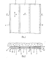
- the panels consist of an aluminum plate, which is provided with a foam filling 3 . They are elongated (see Fig. 1) and have two side edges 4, 5, which run in the longitudinal direction 6 of the panels.
- the first side edge 4 is provided with a strip 7 running in the longitudinal direction 6 and the second side edge 5 is provided with a corresponding groove-like recess 8 running in the longitudinal direction, which is formed by one or more strips, here two strips 8 '. 2 shows, the strips 7 can be inserted into the recesses 8 between the strips 8 '.
- the respective outermost bar or recess can in each case be covered or covered by a profile running in the longitudinal direction of the panel (not shown in the drawing).
- the insertion direction 9 runs essentially in the plane formed by the panels and transversely to the longitudinal direction of the panel.
- the plug connection between the individual panels preferably in the embodiment with the illustrated strips 7 and recesses 8 ', can be made with the aid of a latching mechanism, of which the implementation options are shown in detail in FIGS. 3 to 8 and 10.
- the number of catches or teeth is adapted to the respective structural conditions and requirements.
- FIG. 3 shows how sawtooth-shaped catches 10, 11 and also sawtooth-shaped counter-catches 12, 13 are provided on both sides of the strip 7 and the recess 8.
- the surfaces 10 ', 11' and 12, 13 'lying against each other in the insertion direction 9 are inclined so obliquely to the insertion direction 9 that the insertion is thereby facilitated.
- the other surfaces 10 ′′, 11 ′′ or 12 ′′ and 13 ′′ run approximately vertically and prevent this plug connection from being pulled apart.
- Fig. 3 also shows that the dash-dotted plane 14 of the notches 10 to the corresponding plane 15 of the notches 11 on the other side of the bar 7 can be viewed in the sliding direction 9.
- the division t of this dislocation is preferably the same in each case. The same applies with regard to the corresponding levels 16 and 17 of the counter catches 12, 13 (see FIG. 3). With this, when pressing in the direction of arrow 9, the force acting from the counter-catches 12, 13 of the groove 8 on the catches 10, 11 of the strip 7 is lower than if the catches 10, 11 and counter-catches 12, 13 were each in the same plane the latter embodiment is covered by the invention.
- Fig. 4 shows a cross-sectionally triangular shape of notches and counter detents, the flanks of these triangles each having approximately the same angle of inclination to or opposite to the direction of insertion.
- Fig. 5 shows, also schematically, that detents and counter detents can be arcuate.
- detents and counter detents can also have different shapes, provided that there is only one possibility of latching. Even with these and other possible designs of the catches and counter-catches, these can be offset on both sides on the bar and recess, as is explained with reference to FIG. 3 with the levels 10, 11 and 16, 17.
- Fig. 7 shows a modified embodiment of the strip 18 and recess 19 in that both taper in the insertion direction 9 and have the same shape. You are with.
- Detents 20 and counter detents 21 provided.
- the advantage of the arrangement according to FIG. 7 is that the latching position can be produced with a very short insertion path and thus with a short jerk to a certain extent.
- the insertion path is therefore considerably less than in the case of an embodiment according to FIG. 3.
- one of the lateral boundaries of the recesses 8 formed by the panel protrude beyond the opening thereof in the opposite direction of insertion 9. This is particularly evident from the above strip 22. It not only serves as a correspondingly wide support for the bar 7 of the other end edge of the panel. It can also be used for nailing or screwing on, as indicated by the dash-dotted line 25, of the panels on masonry, while the other end edge of the panel, which has the strip 7 is held by the explained snap-in connection.
- the panel 1 has a preferably metallic, for example aluminum plate-shaped support 26 with a visible surface 27 and an inner surface 28.
- a plate or layer 23 consisting of a heat-insulating material is firmly attached, preferably glued.
- This plate or layer can consist of polystyrene or polyurethane foam.
- the polyurethane foam can be firmly glued to the inner surface 2 8 when it is foamed.
- the carrier 26 can be embossed or deep-drawn.
- the side bar is again with 7 and the associated recess numbered 8.
- the layer or plate 23 protrudes, as shown on the right in FIG. 8, with an edge region analogous to the strip 22 according to Fig. 3.
- possible nailing on the strip 22 is indicated by a dot-dash line with number 25.
- the end faces of the plate or layer 23 which are not covered by the material of the metallic support are numbered 24.
- the elasticity of the insulating material enables a resilient connection when the latching connection 7, 8 is plugged together Giving in of the parts and thus easier manufacture of the locking connection.
- the side of the insulation layer intended to rest on the masonry or the like is numbered 29.
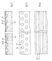
- FIG. 9 shows a more basic illustration of an embodiment of the invention. Identical or essentially identical parts have the same reference numbers.
- the carrier 26 can, as is indicated by the dot-dash line with number 35, limit the lateral front edges to the length a. This leaves the metal-free part b of the total length d.
- the strip 30 of the end edge of this panel on the left in FIG. 9 is located near the support 26, while the strip 31 of the end edge of this panel on the right in FIG. 9 is located near the support surface 29.
- both strips overlap, i.e. the bar 31 of the adjacent panel provided on the left (not shown) is located in room 32 and the bar 30 of the adjacent panel provided on the right (not shown) is located in room 33.
- the attachment to the masonry or the like 34 can also be done by means of nails to be punched through the bar 31 Gluing done.
- the sections 35 covering the end edges according to number 35 ' can still extend parallel to the plate-shaped carrier part up to the points 36. This also means that the area with the thickness b of the insulation layer remains free of metal and therefore does not form a so-called cold bridge. If the covers 35 and 36 of the front edges are dispensed with, the insulation layer 23 can be made thinner than in the previous exemplary embodiments, since the thickness d over which no cold bridge is formed is correspondingly large here.
- FIG. 10 shows an embodiment of the invention which is similar in structure to the example of FIG. 8.
- the carrier 26 ends in front of the connector 7 and the recess 8, e.g. on the edges 37.
- a film 38 made of plastic or a similar deformable material is provided, which, as shown in the drawing, is guided around the side edges of the cladding and forms the locking teeth 39, 40 of the connector strip 7 or the recess 8. This also enables a snap-in connection of panels which can be plugged into one another. If necessary, the insulation layer 23 could extend further downward (similar to the previous exemplary embodiments). This is indicated by a dot-dash line with number 23 '.
- FIGS. 11 to 13 again shows a carrier 26, on the entire inner surface 28 of which a layer 41 made of a polyurethane foam is foamed and thereby glued to this inner surface.
- a further layer 42 made of polystyrene (trademark: Styrofoam) is applied to the still liquid polyurethane foam, which thus presses the polyurethane foam together at the contact surfaces 43 and adheres to it there.
- the polyurethane foam has the function of sound insulation. His job is relatively thin. As a rule, it will not be more than 5 mm.
- the polystyrene layer on the other hand, has the function of thermal insulation.
- the polyurethane foam also reduces the heating and thus the expansion of the sheet of the carrier 26.
- air spaces 44 are provided in the polystyrene layer 42, which primarily serve the air circulation and thus the prevention of condensation. At the same time, they also have the function of thermal insulation. These air spaces 44 are located between knobs 45 or strips 46 of the surface of the polystyrene layer which is visible from above (arrow A) in FIGS. 12 and 13. 12 and 13 show that the air spaces 44 are open to the outside air and therefore flow through it.
- the height of the knobs 45 or strips 46 can be 10 mm. Since they press somewhat into the polyurethane foam, the height h of the air spaces 44 available after completion remains approximately 5 mm in this example. However, it is understood that the invention is not limited to these numbers and to the number of the height of the polyurethane foam.
- an essential advantage of the invention is that a direct plug-in connection of the panels (ie without separate aids, such as separate connecting rails and the like) results in a firm and easy-to-assemble connection, which does not have a greater heat transfer than the panels in their remaining area Has. In particular, direct heat transfer along a butt joint is avoided.
Abstract
Description
Die Erfindung betrifft Paneele gemäß dem Oberbegriff des Anspruches 1. Aus dem DE-GM 7 008 162 sind Blechplatten (keine Paneele) bekannt, wobei zwischen die Blechplatten und dem Mauerwerk Isolierplatten, z.B. aus Polystyrol eingelegt werden. Damit besteht der schwerwiegende Nachteil, daß sich zwischen den Blechplatten und den benachbarten Isolierplatten Kondenswasser bildet, welches insbesondere die Blechplatten aber auch die Isolierplatten angreift und darüber hinaus bei solchen Verkleidungen als gefährdende Feuchtigkeit vermieden werden soll. Zu diesem Zweck sieht die Vorveröffentlichung auch in Befestigungsteilen Öffnungen zur Ableitung des Kondenswassers vor. Solche Öffnungen können sich aber durch Verschmutzung zusetzen. Damit kann das Kondenswasser nicht mehr ablaufen. Ferne sieht die Vorveröffentlichung Befestigungs- oder Haltemittel vor, die sich von der Sichtseite der Blechplatte bis zu dem zu verkleidenden Mauerwerk oder dergl. hin erstrecken. Damit werden dort nachteilig Kältebrücken gebildet.The invention relates to panels according to the preamble of
Aus der DE-DS 32 18 695 ist eine Bauplatte (ebenfalls kein Paneel) bekannt, bestehend aus einer Blechschale, in die eine Dämmstoffschicht aus Mineralwolle eingelegt ist. Auch hier besteht die Gefahr der Kondenswasserbildung zwischen Blechschale und Dämmschicht. An der Schale ist außerdem eine gesonderte Dämmstoffleiste vorgesehen, die an der Dämmstoffschicht anliegt und aus einem anderen Material als diese besteht. Hiermit ist zwischen der Dämmstoffleiste einerseits und der Blechplatte sowie der Dämmstoffschicht andererseits gleichfalls die Gefahr der Kondenswasserbidlung gegeben. Außerdem ist diese Anordnung in der Fertigung relativ aufwendig und in der Praxis nicht stabil genug. Der letztgenannte Nachteil gilt insbesondere dann, wenn derartige Verkleidungen auf einen unebenen Untergrund aufgelegt werden.From DE-DS 32 18 695 a building board (also not a panel) is known, consisting of a sheet metal shell in which an insulating layer of mineral wool is inserted. Here too there is a risk of condensation between the sheet metal shell and the insulation layer. A separate insulation strip is also provided on the shell Insulation layer is applied and made of a different material than this. This also gives the risk of condensation accumulation between the insulation strip on the one hand and the sheet metal plate and the insulation layer on the other. In addition, this arrangement is relatively complex to manufacture and not stable enough in practice. The last-mentioned disadvantage applies in particular when such coverings are placed on an uneven surface.
Ferner kennt man sogenannte Blechpaneele, die langgestreckt und gemäß dem Obergriff des Anspruches 1 ausgebildet sind.Also known are so-called sheet metal panels, which are elongated and designed according to the preamble of
Die Aufgabe der Erfindung besteht demgegenüber darin, ausgehend vom Oberbegriff des Anspruches 1 mit einer einfachen Ausgestaltung die Kondenswasserbildung und auch die Bildung von Kältebrücken zu vermeiden.In contrast, the object of the invention is, based on the preamble of
Die Lösung dieser Aufgabe besteht zunächst, ausgehend vom Oberbegriff des Anspruches 1, in den Merkmalen des Kennzeichens des Anspruches 1. Dabei ist mit "außen" immer die Sichtfläche der Trägers und mit "innen" die gegenüberliegende Fläche des Trägers oder auch die Fläche der Isolierschicht gemeint, die zur Auflage auf die Fassade, das Mauerwerk oder dergleichen kommt. Durch die feste Anlage, bevorzugt Ver-* klebung der Isolierschicht mit dem metallischen Träger ist eine Kondenswasserbidlung nicht mehr möglich. Ferner verhindern die überlappenden Leisten, daß an den Stoßkanten zweier benachbarter Paneele eine sogenannte Kältebrücke gebildet wird, durch die Wärme hindurchtreten kann und daß im Bereich der Stoßkanten sich Kondenswasser bilden kann. Die Merkmale des Anspruches 1 wirken daher auch im Sinne einer Kombination zusammen, die vermeidet, daß Kondenswasser auftritt und bei Frost gefrieren und daß bei gleichzeitigem Vorhandensein einer Kältebrücke dieses Eis sich ausdehnen und zur Beschädigung oder Deformation der Verkleidung führen kann. Hinzu kommt, daß auftretendes Kondenswasser eine Wärmedämmung verhindert und daher eine wesentlich stärkere Isolierschicht bedingt als mit der Erfindung nötig. Die Isolierschicht kann in sich einstückig sein, z.B. aus einem Polyurethanschaum oder auch aus einem Polystyrol, beziehungsweise Polystyrolschaum bestehen. In einer bevorzugten Ausführungsform der Erfindung ist aber die Isolierschicht gemäß Anspruch 14 ausgebildet, der die Kombination einer Schalldämmung mit einer Wärmedämmung beinhaltet. Eine weitere, bevorzugte Ausführungsform ist Gegenstand des Anspruches 15 die weiterhin zur Verhinderung der Kondenswasserbildung beiträgt. Mit den Merkmalen des Anspruches 1 sind auch die Nachteile vermieden, die bei der DE-DS 32 18 695 durch die gesonderte Dämmstoffleiste vorhanden sind. Die Herstellungskosten der erfindungsgemäßen Paneele sind demgegenüber geringer. Ihre Stabilität ist sehr groß, da die in sich einstückige Isolierschicht mit dem Träger eine in sich geschlossene und feste Einheit bildet. Sie kann ohne Gefahr des Verbiegens oder Abbrechens auch auf ein unebenes Nauerwerk gelegt werden.The solution to this problem consists first of all, starting from the preamble of
Mit der Erfindung ist eine Ausgestaltung solcher von langgestreckter Paneele gemäß Anspruch 3 möglich. Hierdurch lassen sich solche Paneele leicht durch Ineinanderstecken miteinz ander verbinden, ohne daß eine schädliche Kältebrücke entsteht.With the invention an embodiment of such elongated panels according to
Eine bevorzugte Ausführungsform der Erfindung ist Gegenstand des Anspruches 6. Hiermit wird das Paneel nach der Erfindung mit den sich überlappenden Leisten zur Schaffung einer Verrastung der einander benachbarten Paneele verwendet, wobei zugleich die Elastizität beziehungsweise Nachgiebigkeit der Isolierschichten ausgenutzt wird. Damit sind die Vorteile der Vermeidung des Wärmedurchganges und Vermeidung der Kondenswasserbildung mit einer in der Montage sehr einfachen und im Halt sehr zuverlässigen Verbindung der aneinander grenzenden Paneele erreicht. Dabei muß auch berücksichtigt werden, daß solche Paneele, auf die sich die Erfindung ausdrücklich bezieht, sehr lang, z.B. bis 20 m lang sein können. Bei derartigen Längen kommt es ganz besonders auf eine leicht zu montierende und fest haltende Verbindung der Paneele untereinander an.A preferred embodiment of the invention is the subject of
Die bisher bekannten Verbindungsmittel aneinander angrenzender Paneele sind nicht befriedigend. So sind z.B. als Verbindungsmittel gemäß der DE-OS 32 43 936 bei Fassadeneinheiten U-förmige Abbiegungen des einen Seitenrandes und hierzu passende S-förmige Abbiegungen des anderen Seitenrandes der Fassadeneinheiten bekannt. Beide Seitenränder werden in Art einer Verhakung miteinander verbunden. Diese vorbekannte Ausführung hat mehrere Nachteile. Die Herstellungskosten für das Verformen der Aluminiumseitenränder sind relativ hoch und ferner bedingt diese Gestaltung der Seitenränder eine relativ große Dicke der Fassadeneinheiten, die aber zum einen einen entsprechenden Mehrbedarf an Aluminiummaterial zur Folge hat und zum anderen erhält dadurch die zu verkleidende Fassade' oder dergleichen einen unerwünscht dicken Auftrag. Wird eine bereits eingehängte Einheit versehentlich etwas aus der fluchtenden Lage mit der Nachbareinheit wieder herausgeschwenkt, so kann sich die Verbindung beider Einheiten ungewollt lösen. Es besteht ferner die Gefahr, daß durch Luftsogwirkung die Verbindungen gelöst werden.The previously known connecting means of adjacent panels are unsatisfactory. For example, known as connecting means according to DE-OS 32 43 936 in facade units U-shaped bends of one side edge and matching S-shaped bends of the other side edge of the facade units. Both side edges are connected to one another in the manner of a hook. This known design has several disadvantages. The manufacturing costs for the deformation of the aluminum side edges are relatively high and furthermore this design of the side edges requires a relatively large thickness of the facade units, which on the one hand results in a correspondingly higher requirement for aluminum material and on the other hand the facade to be cladded 'or the like is thereby undesirable thick order. If an already mounted unit is accidentally swiveled out of the aligned position with the neighboring unit, the connection between the two units can be released unintentionally. There is also a risk that the connections will be loosened by air suction.
Die Vermeidung der vorgenannten Nachteile dient bei dieser bevorzugten Ausführungsform der Erfindung mit zu deren Aufgabenstellung. Das hierdurch mögliche Einstecken der Verrastung in die entsprechende Gegenrastung ist bei der Montage wesentlich einfacher und rascher zu bewerkstelligen als das Einhängen oder gewissermaßen Einfädeln der profilierten Seitenränder gemäß der Ausführung nach DE-OS 32 43 936.In this preferred embodiment of the invention, the avoidance of the abovementioned disadvantages also serves to set the task. The thus possible insertion of the latching into the corresponding counter-latching is much easier and quicker to accomplish during assembly than hanging or threading the profiled side edges according to the design according to DE-OS 32 43 936.
Insbesondere ist es bei diesem Stand der Technik von Nachteil, daß dieses Einfädeln über die gesamte Länge des Paneeles in allen Paneelbereichen zugleich erfolgen muß. Da aber Paneele oft eine sehr große Länge haben (siehe oben), ist eine solche Montage nur schwer durchzuführen. Dagegen kann man mit der einrastenden Steckverbindung nach der Erfindung (wobei die Steckrichtung in der gemeinsamen Ebene der Paneele liegt) zunächst an einem Paneelende beginnen und es dann kontinuierlich bis zum anderen Paneelende fortsetzen. Es genügt bei entsprechender Ausbildung bereits ein Raster und ein zugehöriges Gegenraster, sofern diese die für den Halt der Paneele aneinander erforderlichen Zugkräfte aufnehmen können. Gleichgültig, ob nur je ein Raster und Gegenraster oder mehrere vorgesehen sind, erfordert deren Herstellung fabrikatorisch einen wesentlich geringeren Aufwand als die eingangs erläuterte Verformungsarbeit zur Herstellung von Paneelen nach DE-OS 23 43 936.In particular, it is disadvantageous in this prior art that this threading must take place simultaneously in all panel areas over the entire length of the panel. However, since panels are often very long (see above), such an installation is difficult to carry out. On the other hand, you can start with the snap-in connector according to the invention (the direction of insertion is in the common plane of the panels) first at one end of the panel and then continue to the other end of the panel. With appropriate training, a grid and an associated counter grid are sufficient, provided that they can absorb the tensile forces required to hold the panels together. Regardless of whether only one grid and counter grid or several are provided, their manufacture requires a lot less manufacturing effort than the deformation work for the manufacture of panels according to DE-OS 23 43 936 explained at the beginning.
Bevorzugt ist die Kombination der Verrastung mit den Merkmalen des Anspruches 3. Steckleiste und Ausnehmung sind in fabrikatorisch einfacher Weise mit den Rastern und Gegenrastern zu versehen. Außerdem sichern Steckleiste und Ausnehmung in der verrasteten Einstecklage diese beiden Paneele gegen ein Verschwenken des einen Paneeles zum anderen Paneel aus der gemeinsamen Ebene. Steckleisten und Ausnehmung haben somit eine Doppelfunktion.The combination of the locking with the features of
Die Merkmale des Anspruches 9 ermöglichen das Herstellen der Raster und Gegenraster bereits während des Verformungsvorganges einer Aluminiumplatte zur Trägerplatte.The features of
Die Merkmale der Ansprüche 10 und 11 beinhalten einige Beispiele der Formgebung von Raster und Gegenraster, ohne daß die Erfindung auf diese Beispiele beschränkt ist.The features of
Anspruch 12 zeigt eine andere Möglichkeit der Anordnung von Rasten und Gegenrasten mit dem Effekt, daß beim Eindrücken die zu überwindenden Gegendruckkräfte bei sonst gleicher Profilgestaltung geringer sind als bei einer Anordnung einander gegenüberliegenden Raster in der jeweils gleichen Ebene.
Anspruch 13 sichert den Schutz der jeweils äußersten Leiste bzw. Nut.
Weitere Einzelheiten und Vorteile der Erfindung sind den weiteren Unteransprüchen, sowie der nachfolgenden Beschreibung und der zugehörigen Zeichnung von erfindungsgemäßen Ausführungsmöglichkeiten zu entnehmen. In der Zeichnung zeigt:
- Fig. 1: schematisch in der Draufsicht mehrere miteinander verbundene Paneele,
- Fig. 2: ebenfalls rein schematisch und aus zeichnerischen Gründen unter Weglassung von Raster und Gegenraster einen Schnitt gemäß der Linie II-II in Fig. 1,
- Fig. 3: in einem demgegenüber vergrößerten Maßstab und im Schnitt beide Seitenränder eines bevorzugt nach der Erfindung ausgestalteten Paneeles,
- Fig.4-6:im Maßstab der Fig. 3 mögliche Profilausgestaltungen.
- Fig. 7: im Maßstab der Fig. 3 eine andere Ausführungsform von Nut und Leiste,
- Fig. 8: in einem gegenüber Fig. 3 bis 7 verkleinerten Maßstab eine weitere Ausführungsmöglichkeit der Erfindung,
- Fig. 9: im Schnitt eine Prinzipskizze, welche die gegenüber den metallischen Träger bzw. seiner metallischen Befestigungsmitteln überstehende Isolierschicht zeigt,
- Fig.10: ebenfalls im Schnitt eine Ausführung der Erfindung, die ähnlich der Ausführung nach Fig. 8 ist,
- Fig.11: ebenfalls im Schnitt eine weitere Ausführungsform der Erfindung,
- Fig.12+13: je eine Draufsicht auf eine Ausführungsform der Wärmedämmschicht nach Fig. 11 und zwar in Richtung des Pfeiles A.
- 1: schematically in plan view several interconnected panels,
- 2: also a purely schematic and for drawing reasons, omitting the grid and counter grid, a section along the line II-II in Fig. 1,
- 3: on an enlarged scale and in section, both side edges of a panel preferably designed according to the invention,
- Fig. 4-6: on the scale of Fig. 3 possible profile configurations.
- 7: on the scale of FIG. 3, another embodiment of groove and bar,
- 8: on a reduced scale compared to FIGS. 3 to 7, another possible embodiment of the invention,
- 9: in section a schematic diagram which shows the insulating layer projecting from the metallic carrier or its metallic fastening means,
- 10: also in section an embodiment of the invention, which is similar to the embodiment of FIG. 8,
- 11: also in section a further embodiment of the invention,
- Fig. 12 + 13: a plan view of an embodiment of the thermal barrier coating according to Fig. 11 in the direction of arrow A.
Die Fig. 1 und 2 zeigen drei Paneele 1, die in nicht näher dargestellter Weise an einem Mauerwerk einer Fassade oder dergleichen 2 angebracht sind. Die Paneele bestehen aus einer Aluminiumplatte, die mit einer Schaumstoffüllung 3 versehen ist. Sie sind langgestreckt (siehe Fig. 1) und haben zwei Seitenränder 4, 5, welche in der Längsrichtung 6 der Paneele verlaufen. Dabei ist der erste Seitenrand 4 mit einer in der Längsrichtung 6 verlaufenden Leiste 7 und der zweite Seitenrand 5 mit einer entsprechenden in Längsrichtung verlaufenden nutartigen Ausnehmung 8 versehen, die von ein oder mehreren Leisten, hier zwei Leisten 8', gebildet ist. Wie Fig. 2 zeigt, sind die Leisten 7 in die Ausnehmungen 8 zwischen die Leisten 8' einsteckbar. Die jeweils äußerste Leiste bzw. Ausnehmung kann jeweils durch ein in Längsrichtung des Paneels verlaufendes Profil verkleidet oder abgedeckt sein (in der Zeichnung nicht dargestellt).1 and 2 show three
Die Einsteckrichtung 9 verläuft im wesentlichen in der von den Paneelen gebildeten Ebene und quer zur Paneellängsrichtung. Die Steckverbindung zwischen den einzelnen Paneelen, bevorzugt in der Ausführung mit den erläuterten Leisten 7 und Ausnehmungen 8' kann mit Hilfe einer Verrasterung erfolgen, von der Ausführungsmöglichkeiten in den Fig. 3 bis 8 und 10 im einzelnen dargestellt sind. Die Zahl der Verrasterungen bzw. Zähne wird den jeweiligen baulichen Verhältnissen und Anforderungen angepaßt.The
Fig. 3 zeigt, wie an beiden Seiten der Leiste 7 und der Ausnehmung 8 sägezahnförmige Rasten 10, 11 sowie ebenfalls sägezahnförmige Gegenrasten 12, 13 vorgesehen sind. Die in der Einsteckrichtung 9 aneinander liegenden Flächen 10', 11' bzw. 12, 13'sind derart schräg zur Steckrichtung 9 geneigt, daB hierdurch das Einstecken erleichtert wird. Die anderen Flächen 10", 11" bzw. 12" und 13" verlaufen etwa senkrecht und verhindern ein Auseinanderziehen dieser Steckverbindung.FIG. 3 shows how sawtooth-shaped
Fig. 3 zeigt ferner, daß die strichpunktiert angedeutete Ebene 14 der Rasten 10 zur entsprechenden Ebene 15 der Rasten 11 auf der anderen Seite der Leiste 7 in der Schieberichtung 9 betrachtet versetzt sein kann. Die Teilung t dieser Versetzung ist bevorzugt jeweils gleich. Das gleiche gilt hinsichtlich der entsprechenden Ebenen 16 und 17 der Gegenrasten 12, 13 (siehe Fig. 3). Hiermit wird beim Eindrücken in Pfeilrichtung 9 die von den Gegenrasten 12, 13 der Nut 8 auf die Rasten 10, 11 der Leiste 7 einwirkende Kraft geringer, als wenn die Rasten 10, 11 und Gegenrasten 12, 13 jeweils in der gleichen Ebene wären Aber auch die letztgenannte Ausführungsform wird von der Erfindung mit erfaßt.Fig. 3 also shows that the dash-dotted
Fig. 4 zeigt eine im Querschnitt dreieckförmige Form von Rasten und Gegenrasten, wobei die Flanken dieser Dreiecke etwa jeweils die gleiche Winkelneigung zur Einsteckrichtung, bzw. dazu entgegengesetzt haben. Fig. 5 zeigt, ebenfalls schematisch, daß Rasten und Gegenrasten bogenförmig sein können. Gemäß Fig. 6 können Rasten und Gegenrasten auch unterschiedliche Formen haben, sofern nur eine Einrastmöglichkeit besteht. Auch bei diesen und anderen möglichen Gestaltungen der Rasten und Gegenrasten können diese beidseitig an Leiste und Ausnehmung zueinander versetzt sein, wie es anhand der Fig. 3 mit den Ebenen 10, 11 und 16, 17 erläutert ist.Fig. 4 shows a cross-sectionally triangular shape of notches and counter detents, the flanks of these triangles each having approximately the same angle of inclination to or opposite to the direction of insertion. Fig. 5 shows, also schematically, that detents and counter detents can be arcuate. According to FIG. 6, detents and counter detents can also have different shapes, provided that there is only one possibility of latching. Even with these and other possible designs of the catches and counter-catches, these can be offset on both sides on the bar and recess, as is explained with reference to FIG. 3 with the
Fig. 7 zeigt eine abgewandelte Ausführungsform von Leiste 18 und Ausnehmung 19, indem beide in der Steckrichtung 9 sich verjüngen und dabei die gleiche Form haben. Sie sind mit . Rasten 20 und Gegenrasten 21 versehen. Hierzu wird auf die vorstehend geschilderten Ausführungsmöglichkeiten von Rasten und Gegenrasten, einschließlich deren Versetzung, verwiesen. Der Vorteil der Anordnung nach Fig. 7 liegt darin, daß mit einem sehr kurzen Einschiebeweg und damit gewissermaßen mit einem kurzen Ruck die Rastlage herstellbar ist. Der Einschubweg ist hier also wesentlich geringer als bei einer Ausführungsform gemäß Fig. 3. Bei dieser Ausführung nach Fig. 7 empfiehlt sich besonders eine Ausgestaltung von Rasten und Gegenrasten derart, daß sie ein Wiederherausziehen verhindern, z.B. durch eine Sägezahnform gemäß Fig. 3.Fig. 7 shows a modified embodiment of the
In sämtlichen geschilderten Möglichkeiten der Verrastung der Paneele miteinander ist die Gefahr vermieden, daß durch Wind bzw. durch Luftströmungen auftretende Sogwirkungen die Paneele voneinander lösen. Es sind hiermit auch größere Paneelbreiten als bisher möglich. Mit dem Einrastvorgang beim Einstecken ziehen sich die Paneele mit Hilfe dieserrasterungen in die gewünschte Endlage. Man kann dabei aber - falls gewünscht - bewußt die Leisten nicht vollständig in die Nuten eindrücken, d.h. eine oder sogar zwei Rastteilungen vorher mit dem Einsteckvorgang aufhören. Hierdurch kann eine sogenannte Schattenfuge zwischen zwei aneinander angrenzenden Paneelen gebildet werden, die einen besonderen optischen und damit architektonischen Effekt ergibt. Die Verrasterungen haben eine gewisse Elastizität und halten den im Betrieb auftretenden Temperaturänderungen stand.In all of the described possibilities for locking the panels together, the risk is avoided that suction effects occurring due to wind or air currents detach the panels from one another. This means that larger panel widths than previously possible. With the snap-in process when inserting, the panels pull into the desired end position with the help of these catches. However, if desired, you can deliberately not press the strips completely into the grooves, i.e. stop inserting one or even two rest stops beforehand. In this way, a so-called shadow gap can be formed between two adjoining panels, which results in a special visual and thus architectural effect. The catches have a certain elasticity and withstand the temperature changes that occur during operation.
Es empfiehlt sich, die Rasten und Gegenrasten aus einem stabilen Material zu machen, bevorzugt aus dem Material der Aluminium-Trägerplatte mit herzustellen, z.B. zu prägen. Im übrigen kann, wie Fig. 3 und auch die nachstehend zu erläuternde Fig. 8 zeigt, eine der vom Paneel gebildeten seitlichen Begrenzungen der Ausnehmungen 8 über deren Öffnung entgegen der Einsteckrichtung 9 vorstehen. Diese ist besonders aus der vorstehenden Leiste 22 ersichtlich. Sie dient nicht nur als entsprechend breite Auflage für die Leiste 7 der anderen Stirnkante des Paneeles. Sie kann auch zum Annageln oder Anschrauben, wie es mit der strichpunktierten Linie 25 angedeutet ist, der Paneele an Mauerwerk dienen, während die andere, die Leiste 7 aufweisende Stirnkante des Paneels durch die erläuterte Steck-Rastverbindung gehalten wird.It is advisable to make the catches and counter-catches from a stable material, preferably to produce them from the material of the aluminum carrier plate, for example to emboss them. Otherwise, as shown in FIG. 3 and also FIG. 8 to be explained below, one of the lateral boundaries of the
Fig. 8 zeigt eine bevorzugte, in der Praxis besonders vorteilhafte Ausführungsform der Erfindung. Das Paneel 1 besitzt einen bevorzugt metallischen, z.B. aus Aluminium bestehendenplattenförmigen Träger 26 mit einer Sichtfläche 27 und einer Innenfläche 28. An der Innenfläche ist eine aus einem wärmedämmenden Material bestehende Platte oder Schicht 23 fest angebracht, bevorzugt angeklebt. Diese Platte oder Schicht kann aus Polystyrol oder Polyurethanschaum bestehen. Dabei kann der Polyurethanschaum bei seinem Ausschäumen fest mit der Innenfläche 28 verklebt werden. Der Träger 26 kann geprägt oder tiefgezogen sein. Der Träger 26 mit seinen Randbereichen 26', 26" erstreckt sich aber nur über den Teilbereich a der Gesamtdicke d dieses Paneeles, so daß im weiteren Teilbereich b keine Kältebrücke durch metallische Teile entstehen kann. Die seitliche Leiste ist wieder mit 7 und die zugehörige Ausnehmung mit 8 beziffert. Die Schicht oder Platte 23 steht, wie Fig. 8 rechts zeigt, mit einer der Leiste 22 gemäß Fig. 3 analogem Randbereich vor. Er wird ebenso wie im Beispiel Fig. 3 von der Leiste 7 der anderen Stirnkante überlappt. Die auch hier bei der Leiste 22 mögliche Nagel.ung ist mit Ziffer 25 strichpunktiert angedeutet. Die nicht vom Material des metallischen Trägers bedeckten Stirnflächen der Platte oder Schicht 23 sind mit 24 beziffert. Die Elastizität des Dämmateriales ermöglicht beim Zusammenstecken der Rastverbindung 7, 8 ein federndes Nachgeben der Teile und damit eine leichtere Herstellung der Rastverbindung.8 shows a preferred embodiment of the invention which is particularly advantageous in practice. The
Die jeweils zur Auflage auf das Mauerwerk oder dergleichen bestimmte Seite der Dämmschicht ist mit 29 beziffert.The side of the insulation layer intended to rest on the masonry or the like is numbered 29.
Das Beispiel der Fig. 9 zeigt eine mehr prinzipielle .Darstellung einer Ausgestaltungsmöglichkeit der Erfindung. Identische oder im wesentlichen gleiche Teile tragen die gleichen Bezugsziffern. Der Träger 26 kann, wie es strichpunktiert mit Ziffer 35 angedeutet ist, die seitlichen Stirnkanten auf der Länge a begrenzen. Damit bleibt aber von der Gesamtlänge d immer noch der metallfreie Teil b übrig. Die Leiste 30 der in Fig. 9 links liegenden Stirnkante dieses Paneeles befindet sich in der Nähe des Trägers 26, während die Leiste 31 der in Fig. 9 rechts gelegenen Stirnkante dieses Paneeles sich nahe der Auflagefläche 29 befindet. Beim Verlegen der Paneele überlappen sich beide Leisten, d.h. die Leiste 31 des links vorgesehenen Nachbarpaneeles ( nicht dargestellt ) befindet sich im Raum 32 und die Leiste 30 des rechts vorgesehenen Nachbarpaneeles (nicht dargestellt) im Raum 33. Die Befestigung am Mauerwerk oder dergleichen 34 kann mittels durch die Leiste 31 hindurchzuschlagender Nägel aber auch durch Verkleben erfolgen.The example in FIG. 9 shows a more basic illustration of an embodiment of the invention. Identical or essentially identical parts have the same reference numbers. The
Erwähnt sei, daß die die Stirnkanten bedeckenden Abschnitte 35 gemäß Ziffer 35' sich parallel zum plattenförmigen Trägerteil noch bis zu den Stellen 36 erstrecken können. Auch hiermit bleibt der Bereich mit der Dicke b der Dämmschicht frei von Metall und bildet daherkeine sogenannte Kältebrücke. Falls man auf die Abdeckungen 35 und 36 der Stirnkanten verzichtet, kann die Dämmschicht 23 dünner als in den vorhergehenden Ausführungsbeispielen gemacht werden, da die Dicke d, über die keine Kältebrücke entsteht, hier entsprechend groß ist.It should be mentioned that the
Eine ähnliche Ausgestaltung wäre auch bei der zuvor erläuterten Fig. 8 denkbar, indem man dort zwar die Umhüllungen bzw. Auskleidungen 26', bzw. 26" beibehält, jedoch auf Rasten und Gegenrasten an der Steckleiste 7 und in der Ausnehmung 8 verzichtet.A similar configuration would also be conceivable in the case of FIG. 8 explained above, in that the coverings or
Fig. 10 zeigt eine Ausführungsform der Erfindung, die in ihrem Aufbau dem Beispiel der Fig. 8 ähnelt. Hierbei endet der Träger 26 bereits vor der Steckleiste 7 und der Ausnehmung 8, z.B. an den Kanten 37. Zusätzlich ist noch eine Folie 38 aus Kunststoff oder einem ähnlichen verformbaren Werkstoff vorgesehen, welche gemäß der Zeichnung um die Seitenränder der Verkleidung herumgeführt ist und die Rastverzahnungen 39, 40 der Steckleiste 7 bzw. der Ausnehmung 8 bildet. Auch hierdurch ist eine Rastverbindung ineinander steckbarer Paneele möglich. Bei Erfordernis könnte sich die Dämmschicht 23 noch weiter nach unten erstrecken (ähnlich den vorhergehenden Ausführungsbeispielen). Dies ist strichpunktiert mit Ziffer 23' angedeutet.FIG. 10 shows an embodiment of the invention which is similar in structure to the example of FIG. 8. Here, the
Das Ausführungsbeispiel der Figuren 11 bis 13 zeigt wieder einen Träger 26, auf dessen gesamter Innenfläche 28 eine Schicht 41 aus einem Polyurethanschaum aufgeschäumt und dabei mit dieser Innenfläche verklebt ist. Auf den noch flüssigen Polyurethanschaum wird eine weitere Schicht 42 aus Polystyrol (Warenzeichen: Styropor) aufgebracht, die damit an den Berührungsflächen 43 den Polyurethanschaum zusammenpreßt und sich dort mit ihm verklebt. Der Polyurethanschaum hat die Funktion der Schalldämmung. Sein Auftrag ist relativ dünn. Er wird in der Regel nicht mehr als 5 mm betragen. Die Polystyrolschicht hat dagegen die Funktion der Wärmedämmung. Hinzu kommt, daB auch der Polyurethanschaum die Erwärmung und damit Dehnung des Bleches des Trägers 26 reduziert. Ferner sind in der Polystyrolschicht 42 Lufträume 44 vorgesehen, die primär der Luftzirkulation und damit der Verhinderung von Kondenswasserbildung dienen. Zugleich haben sie aber auch die Funktion der Wärmedämmung. Diese Lufträume 44 befinden sich zwischen Noppen 45 oder Leisten 46 der in den Fig. 12 und 13 von oben (Pfeil A) sichtbaren Fläche der Polystyrolschicht. Die Fig. 12 und 13 zeigen, daß die Lufträume 44 zur Außenluft hin offen sind und daher von dieser durchströmt werden. Die Höhe der Noppen 45 oder Leisten 46 kann 10 mm betragen. Da sie sich etwas in den Polyurethanschaum eindrücken, verbleibt als nach Fertigstellung zur Verfügung stehenden Höhe h der Lufträume 44 in diesem Beispiel etwa 5 mm. Es versteht sich aber, daß die Erfindung nicht auf diese Zahlen und auf die Zahlenangabe der Höhe des Polyurethanschaumes beschränkt ist.The exemplary embodiment in FIGS. 11 to 13 again shows a
Ein fertigungstechnisch und hinsichtlich der Wärmedämmung wesentlicher Vorteil der Erfindung besteht darin, daß eine direkte Steckverbindung der Paneele (d.h. ohne gesonderte Hilfsmittel, wie gesonderte Verbindungsschienen und dergleichen) eine feste und leicht montierbare Verbindung ergibt, die keinen größeren Wärmedurchgang als die Paneele in ihrem übrigen Bereich hat. Insbesondere ist ein direkter Wärmedurchgang entlang einer Stoßfuge vermieden.A manufacturing advantage and with regard to thermal insulation, an essential advantage of the invention is that a direct plug-in connection of the panels (ie without separate aids, such as separate connecting rails and the like) results in a firm and easy-to-assemble connection, which does not have a greater heat transfer than the panels in their remaining area Has. In particular, direct heat transfer along a butt joint is avoided.
Im übrigen gilt, daß die bei einem Ausführungsbeispiel dargestellten und beschriebenen Merkmale sinngemäß auch bei einem anderen Ausführungsbeispiel vorgesehen sein können.Moreover, the features shown and described in one embodiment can also be provided in a corresponding manner in another embodiment.
Claims (15)
Applications Claiming Priority (4)
| Application Number | Priority Date | Filing Date | Title |
|---|---|---|---|
| DE3512204 | 1985-04-03 | ||
| DE19853512206 DE3512206A1 (en) | 1985-04-03 | 1985-04-03 | Panels for cladding facades or the like |
| DE19853512204 DE3512204A1 (en) | 1985-04-03 | 1985-04-03 | Cladding of exterior walls of buildings |
| DE3512206 | 1985-04-03 |
Publications (2)
| Publication Number | Publication Date |
|---|---|
| EP0196672A2 true EP0196672A2 (en) | 1986-10-08 |
| EP0196672A3 EP0196672A3 (en) | 1987-05-13 |
Family
ID=25831058
Family Applications (1)
| Application Number | Title | Priority Date | Filing Date |
|---|---|---|---|
| EP86104540A Withdrawn EP0196672A3 (en) | 1985-04-03 | 1986-04-03 | Panels to cover the exterior walls of buildings |
Country Status (1)
| Country | Link |
|---|---|
| EP (1) | EP0196672A3 (en) |
Cited By (19)
| Publication number | Priority date | Publication date | Assignee | Title |
|---|---|---|---|---|
| EP0311700A1 (en) * | 1987-10-13 | 1989-04-19 | Herbert Heinemann | Facing element and method to make same |
| DE3908063A1 (en) * | 1989-03-13 | 1990-09-20 | Herbert Heinemann | Sheet-metal facing element |
| FR2678304A1 (en) * | 1991-06-26 | 1992-12-31 | Fourgeaud Monique | Insulating panel and method for manufacturing it |
| US5454199A (en) * | 1994-07-01 | 1995-10-03 | I.S.M., Inc. | Wall clip for concrete forming system |
| US6497079B1 (en) | 2000-03-07 | 2002-12-24 | E.F.P. Floor Products Gmbh | Mechanical panel connection |
| EP1273737A2 (en) * | 1999-04-12 | 2003-01-08 | Premark RWP Holdings, Inc. | Article with interlocking edges and covering product prepared therefrom |
| US6526719B2 (en) | 2000-03-07 | 2003-03-04 | E.F.P. Floor Products Gmbh | Mechanical panel connection |
| US6647689B2 (en) | 2002-02-18 | 2003-11-18 | E.F.P. Floor Products Gmbh | Panel, particularly a flooring panel |
| WO2005124052A1 (en) * | 2004-06-17 | 2005-12-29 | Kronospan Technical Company Ltd. | Multi-positionable wall or ceiling panel |
| EP1726735A1 (en) * | 2005-05-23 | 2006-11-29 | MBS Spanplattenbeschichtungs GmbH | Wall covering system |
| US7698868B2 (en) * | 1996-06-11 | 2010-04-20 | Unilin Beheer B.V. Besloten Vennootschap | Floor panels with edge connectors |
| NL2003023C2 (en) * | 2009-06-15 | 2010-12-16 | M3C Ingenieursburo | BUILDING ELEMENT AND METHOD FOR BUILDING A WALL. |
| WO2013060871A1 (en) * | 2011-10-27 | 2013-05-02 | Nmc S.A. | Foam blade having connection means |
| US8627631B2 (en) | 2000-06-20 | 2014-01-14 | Flooring Industries Limited, Sarl | Floor covering |
| US9255414B2 (en) | 2000-03-31 | 2016-02-09 | Pergo (Europe) Ab | Building panels |
| US9464444B2 (en) | 2010-01-15 | 2016-10-11 | Pergo (Europe) Ab | Set of panels comprising retaining profiles with a separate clip and method for inserting the clip |
| US9464443B2 (en) | 1998-10-06 | 2016-10-11 | Pergo (Europe) Ab | Flooring material comprising flooring elements which are assembled by means of separate flooring elements |
| US9593491B2 (en) | 2010-05-10 | 2017-03-14 | Pergo (Europe) Ab | Set of panels |
| CN113530120A (en) * | 2021-05-28 | 2021-10-22 | 深圳文业装饰设计工程有限公司 | Installation method of honeycomb sound-absorbing wood veneer structure |
Citations (10)
| Publication number | Priority date | Publication date | Assignee | Title |
|---|---|---|---|---|
| US2779979A (en) * | 1953-03-16 | 1957-02-05 | Barclay Mfg Co Inc | Wall and wall unit construction |
| FR1581384A (en) * | 1967-09-20 | 1969-09-12 | ||
| BE742486A (en) * | 1969-12-02 | 1970-05-14 | ||
| FR2081712A1 (en) * | 1970-03-05 | 1971-12-10 | Alcan Aluminiumwerke | |
| FR2116716A5 (en) * | 1970-12-04 | 1972-07-21 | Sullhofer Heinz | Insulation panel - with rigid polyurethane core and cover layer of reinforced metal or plastics plate |
| FR2143180A1 (en) * | 1971-06-24 | 1973-02-02 | Alcan Aluminiumwerke | |
| DE2405902A1 (en) * | 1974-02-07 | 1975-08-21 | Martin Gabler | Rectangular prefabricated insulating plate for refrigerators - has tongue and groove edge connectors moulded into plate |
| CH602968A5 (en) * | 1975-09-26 | 1978-08-15 | Paul Gaehwyler | Plastics, thermally and acoustically insulating cladding material |
| AT364501B (en) * | 1980-05-19 | 1981-10-27 | Hans Ing Taborsky | CLADDING ELEMENT, PARTICULARLY WALL OR ROOF ELEMENT |
| DE3218695A1 (en) * | 1982-03-31 | 1983-10-06 | Rib Roof Dachprofile Gmbh & Co | Structural panel |
-
1986
- 1986-04-03 EP EP86104540A patent/EP0196672A3/en not_active Withdrawn
Patent Citations (10)
| Publication number | Priority date | Publication date | Assignee | Title |
|---|---|---|---|---|
| US2779979A (en) * | 1953-03-16 | 1957-02-05 | Barclay Mfg Co Inc | Wall and wall unit construction |
| FR1581384A (en) * | 1967-09-20 | 1969-09-12 | ||
| BE742486A (en) * | 1969-12-02 | 1970-05-14 | ||
| FR2081712A1 (en) * | 1970-03-05 | 1971-12-10 | Alcan Aluminiumwerke | |
| FR2116716A5 (en) * | 1970-12-04 | 1972-07-21 | Sullhofer Heinz | Insulation panel - with rigid polyurethane core and cover layer of reinforced metal or plastics plate |
| FR2143180A1 (en) * | 1971-06-24 | 1973-02-02 | Alcan Aluminiumwerke | |
| DE2405902A1 (en) * | 1974-02-07 | 1975-08-21 | Martin Gabler | Rectangular prefabricated insulating plate for refrigerators - has tongue and groove edge connectors moulded into plate |
| CH602968A5 (en) * | 1975-09-26 | 1978-08-15 | Paul Gaehwyler | Plastics, thermally and acoustically insulating cladding material |
| AT364501B (en) * | 1980-05-19 | 1981-10-27 | Hans Ing Taborsky | CLADDING ELEMENT, PARTICULARLY WALL OR ROOF ELEMENT |
| DE3218695A1 (en) * | 1982-03-31 | 1983-10-06 | Rib Roof Dachprofile Gmbh & Co | Structural panel |
Cited By (49)
| Publication number | Priority date | Publication date | Assignee | Title |
|---|---|---|---|---|
| EP0311700A1 (en) * | 1987-10-13 | 1989-04-19 | Herbert Heinemann | Facing element and method to make same |
| DE3908063A1 (en) * | 1989-03-13 | 1990-09-20 | Herbert Heinemann | Sheet-metal facing element |
| FR2678304A1 (en) * | 1991-06-26 | 1992-12-31 | Fourgeaud Monique | Insulating panel and method for manufacturing it |
| US5454199A (en) * | 1994-07-01 | 1995-10-03 | I.S.M., Inc. | Wall clip for concrete forming system |
| US7726089B2 (en) * | 1996-06-11 | 2010-06-01 | Unilin Beheer B.V., Besloten Vennootschap | Floor panels with edge connectors |
| US7698868B2 (en) * | 1996-06-11 | 2010-04-20 | Unilin Beheer B.V. Besloten Vennootschap | Floor panels with edge connectors |
| US8997429B2 (en) | 1996-06-11 | 2015-04-07 | Unilin Beheer B.V. | Floor panels with edge connectors |
| US7770350B2 (en) * | 1996-06-11 | 2010-08-10 | Unilin Beheer B. V., besloten vennootschap | Floor panels with edge connectors |
| US9464443B2 (en) | 1998-10-06 | 2016-10-11 | Pergo (Europe) Ab | Flooring material comprising flooring elements which are assembled by means of separate flooring elements |
| EP1273737A3 (en) * | 1999-04-12 | 2003-07-16 | Premark RWP Holdings, Inc. | Article with interlocking edges and covering product prepared therefrom |
| EP1273737A2 (en) * | 1999-04-12 | 2003-01-08 | Premark RWP Holdings, Inc. | Article with interlocking edges and covering product prepared therefrom |
| US6526719B2 (en) | 2000-03-07 | 2003-03-04 | E.F.P. Floor Products Gmbh | Mechanical panel connection |
| US6497079B1 (en) | 2000-03-07 | 2002-12-24 | E.F.P. Floor Products Gmbh | Mechanical panel connection |
| US10156078B2 (en) | 2000-03-31 | 2018-12-18 | Pergo (Europe) Ab | Building panels |
| US9677285B2 (en) | 2000-03-31 | 2017-06-13 | Pergo (Europe) Ab | Building panels |
| US9611656B2 (en) | 2000-03-31 | 2017-04-04 | Pergo (Europe) Ab | Building panels |
| US9534397B2 (en) | 2000-03-31 | 2017-01-03 | Pergo (Europe) Ab | Flooring material |
| US10233653B2 (en) | 2000-03-31 | 2019-03-19 | Pergo (Europe) Ab | Flooring material |
| US9316006B2 (en) | 2000-03-31 | 2016-04-19 | Pergo (Europe) Ab | Building panels |
| US9260869B2 (en) | 2000-03-31 | 2016-02-16 | Pergo (Europe) Ab | Building panels |
| US9255414B2 (en) | 2000-03-31 | 2016-02-09 | Pergo (Europe) Ab | Building panels |
| US10626619B2 (en) | 2000-03-31 | 2020-04-21 | Unilin Nordic Ab | Flooring material |
| US9068356B2 (en) | 2000-06-20 | 2015-06-30 | Flooring Industries Limited, Sarl | Floor covering |
| US9388586B1 (en) | 2000-06-20 | 2016-07-12 | Flooring Industries Limited, Sarl | Floor covering |
| US8793958B2 (en) | 2000-06-20 | 2014-08-05 | Flooring Industries Limited, Sarl | Floor covering |
| US9234356B2 (en) | 2000-06-20 | 2016-01-12 | Flooring Industries Limited, Sarl | Floor covering |
| US8904729B2 (en) | 2000-06-20 | 2014-12-09 | Flooring Industries Limited, Sarl | Floor covering |
| US8631625B2 (en) | 2000-06-20 | 2014-01-21 | Flooring Industries Limited, Sarl | Floor covering |
| US8627631B2 (en) | 2000-06-20 | 2014-01-14 | Flooring Industries Limited, Sarl | Floor covering |
| US9334657B2 (en) | 2000-06-20 | 2016-05-10 | Flooring Industries Limted, Sarl | Floor covering |
| US9376823B1 (en) | 2000-06-20 | 2016-06-28 | Flooring Industries Limited, Sarl | Floor covering |
| US9856657B2 (en) | 2000-06-20 | 2018-01-02 | Flooring Industries Limited, Sarl | Floor covering |
| US9388585B1 (en) | 2000-06-20 | 2016-07-12 | Flooring Industries Limited, Sarl | Floor covering |
| US9394699B1 (en) | 2000-06-20 | 2016-07-19 | Flooring Industries Limited, Sarl | Floor covering |
| US9624676B2 (en) | 2000-06-20 | 2017-04-18 | Flooring Industries Limited, Sarl | Floor covering |
| US10407920B2 (en) | 2000-06-20 | 2019-09-10 | Flooring Industries Limited, Sarl | Floor covering |
| US9482013B2 (en) | 2000-06-20 | 2016-11-01 | Flooring Industries Limited, Sarl | Floor covering |
| US10125498B2 (en) | 2000-06-20 | 2018-11-13 | Flooring Industries Limited, Sarl | Floor covering |
| US6647689B2 (en) | 2002-02-18 | 2003-11-18 | E.F.P. Floor Products Gmbh | Panel, particularly a flooring panel |
| WO2005124052A1 (en) * | 2004-06-17 | 2005-12-29 | Kronospan Technical Company Ltd. | Multi-positionable wall or ceiling panel |
| US8793956B2 (en) | 2004-06-17 | 2014-08-05 | Kronoplus Technical Ag | Multi-positionable wall or ceiling panel |
| EP1726735A1 (en) * | 2005-05-23 | 2006-11-29 | MBS Spanplattenbeschichtungs GmbH | Wall covering system |
| NL2003023C2 (en) * | 2009-06-15 | 2010-12-16 | M3C Ingenieursburo | BUILDING ELEMENT AND METHOD FOR BUILDING A WALL. |
| EP2278088A2 (en) * | 2009-06-15 | 2011-01-26 | M3C Ingenieursburo | Construction element and method for constructing a wall |
| US9464444B2 (en) | 2010-01-15 | 2016-10-11 | Pergo (Europe) Ab | Set of panels comprising retaining profiles with a separate clip and method for inserting the clip |
| US9593491B2 (en) | 2010-05-10 | 2017-03-14 | Pergo (Europe) Ab | Set of panels |
| WO2013060871A1 (en) * | 2011-10-27 | 2013-05-02 | Nmc S.A. | Foam blade having connection means |
| BE1020286A5 (en) * | 2011-10-27 | 2013-07-02 | Nmc Sa | FOAM BLADE FOR MULTI-BLADE ASSEMBLIES. |
| CN113530120A (en) * | 2021-05-28 | 2021-10-22 | 深圳文业装饰设计工程有限公司 | Installation method of honeycomb sound-absorbing wood veneer structure |
Also Published As
| Publication number | Publication date |
|---|---|
| EP0196672A3 (en) | 1987-05-13 |
Similar Documents
| Publication | Publication Date | Title |
|---|---|---|
| EP0196672A2 (en) | Panels to cover the exterior walls of buildings | |
| DE3538538C2 (en) | ||
| EP0652332B1 (en) | Heat insulating panel made of fibrous insulating material or cork | |
| EP0006431A1 (en) | Hollow building panel of extruded plastics | |
| DE29825211U1 (en) | Industrial building and enclosure insulated casket-like wall panel - has sheet steel skin with edge flanges bent to form claws for gripping mineral wool insulating panel enclosed between flanges | |
| DE202005021844U1 (en) | Two-piece end profile for insulation boards | |
| EP0796963A1 (en) | Cover strip for the external insulations of buildings | |
| EP0004005B1 (en) | Wall element | |
| DE4239051A1 (en) | Insulated panels on building wall facade - have corrugated front surfaces shaped to hold plastics or stone cladding panels | |
| DE2730525A1 (en) | Mineral fibre or foamed insulation panel fixture - involves two sheet metal pieces with pointed tongue bent through slit | |
| EP0940518A1 (en) | Cladding element for covering building walls | |
| AT413414B (en) | METAL SHUTTER COVER FOR ROOFS OR FACADES | |
| DE3426653A1 (en) | Roof dormer | |
| EP1905919A2 (en) | Pedestal cover profile | |
| DE202006009485U1 (en) | Two-piece closure profile for insulating wall panels of buildings, has guiding side piece with base unit and fastening unit provided at base unit and fastened with attachment section during assembly at guiding side piece | |
| DE3528316A1 (en) | Support rail profile for coverings | |
| EP0440177B1 (en) | Shuttering for concrete construction | |
| DE19708868C2 (en) | Prefabricated cladding element for cladding building walls | |
| DE19718449A1 (en) | Building insulation panel end rail | |
| DE3512206A1 (en) | Panels for cladding facades or the like | |
| CH648084A5 (en) | Profiled plastering screed | |
| EP0512135A1 (en) | Reinforcement or supporting plate | |
| AT397400B (en) | Connecting element for the layers of a multi-layer masonry structure | |
| EP2446094B1 (en) | Support section for a facade system | |
| DE4440131A1 (en) | Fastening arrangement for rigid heat insulation plates between roof rafters |
Legal Events
| Date | Code | Title | Description |
|---|---|---|---|
| PUAI | Public reference made under article 153(3) epc to a published international application that has entered the european phase |
Free format text: ORIGINAL CODE: 0009012 |
|
| AK | Designated contracting states |
Kind code of ref document: A2 Designated state(s): AT BE CH DE FR GB LI LU NL |
|
| PUAL | Search report despatched |
Free format text: ORIGINAL CODE: 0009013 |
|
| AK | Designated contracting states |
Kind code of ref document: A3 Designated state(s): AT BE CH DE FR GB LI LU NL |
|
| STAA | Information on the status of an ep patent application or granted ep patent |
Free format text: STATUS: THE APPLICATION IS DEEMED TO BE WITHDRAWN |
|
| 18D | Application deemed to be withdrawn |
Effective date: 19880113 |