EP0195018B1 - Reconstitution device - Google Patents
Reconstitution device Download PDFInfo
- Publication number
- EP0195018B1 EP0195018B1 EP19850904182 EP85904182A EP0195018B1 EP 0195018 B1 EP0195018 B1 EP 0195018B1 EP 19850904182 EP19850904182 EP 19850904182 EP 85904182 A EP85904182 A EP 85904182A EP 0195018 B1 EP0195018 B1 EP 0195018B1
- Authority
- EP
- European Patent Office
- Prior art keywords
- drug
- vial
- container
- wall
- reconstitution
- Prior art date
- Legal status (The legal status is an assumption and is not a legal conclusion. Google has not performed a legal analysis and makes no representation as to the accuracy of the status listed.)
- Expired - Lifetime
Links
Images


Classifications
-
- A—HUMAN NECESSITIES
- A61—MEDICAL OR VETERINARY SCIENCE; HYGIENE
- A61J—CONTAINERS SPECIALLY ADAPTED FOR MEDICAL OR PHARMACEUTICAL PURPOSES; DEVICES OR METHODS SPECIALLY ADAPTED FOR BRINGING PHARMACEUTICAL PRODUCTS INTO PARTICULAR PHYSICAL OR ADMINISTERING FORMS; DEVICES FOR ADMINISTERING FOOD OR MEDICINES ORALLY; BABY COMFORTERS; DEVICES FOR RECEIVING SPITTLE
- A61J1/00—Containers specially adapted for medical or pharmaceutical purposes
- A61J1/14—Details; Accessories therefor
- A61J1/20—Arrangements for transferring or mixing fluids, e.g. from vial to syringe
- A61J1/2089—Containers or vials which are to be joined to each other in order to mix their contents
-
- A—HUMAN NECESSITIES
- A61—MEDICAL OR VETERINARY SCIENCE; HYGIENE
- A61J—CONTAINERS SPECIALLY ADAPTED FOR MEDICAL OR PHARMACEUTICAL PURPOSES; DEVICES OR METHODS SPECIALLY ADAPTED FOR BRINGING PHARMACEUTICAL PRODUCTS INTO PARTICULAR PHYSICAL OR ADMINISTERING FORMS; DEVICES FOR ADMINISTERING FOOD OR MEDICINES ORALLY; BABY COMFORTERS; DEVICES FOR RECEIVING SPITTLE
- A61J1/00—Containers specially adapted for medical or pharmaceutical purposes
- A61J1/05—Containers specially adapted for medical or pharmaceutical purposes for collecting, storing or administering blood, plasma or medical fluids ; Infusion or perfusion containers
- A61J1/10—Bag-type containers
-
- A—HUMAN NECESSITIES
- A61—MEDICAL OR VETERINARY SCIENCE; HYGIENE
- A61J—CONTAINERS SPECIALLY ADAPTED FOR MEDICAL OR PHARMACEUTICAL PURPOSES; DEVICES OR METHODS SPECIALLY ADAPTED FOR BRINGING PHARMACEUTICAL PRODUCTS INTO PARTICULAR PHYSICAL OR ADMINISTERING FORMS; DEVICES FOR ADMINISTERING FOOD OR MEDICINES ORALLY; BABY COMFORTERS; DEVICES FOR RECEIVING SPITTLE
- A61J1/00—Containers specially adapted for medical or pharmaceutical purposes
- A61J1/14—Details; Accessories therefor
- A61J1/1475—Inlet or outlet ports
-
- A—HUMAN NECESSITIES
- A61—MEDICAL OR VETERINARY SCIENCE; HYGIENE
- A61J—CONTAINERS SPECIALLY ADAPTED FOR MEDICAL OR PHARMACEUTICAL PURPOSES; DEVICES OR METHODS SPECIALLY ADAPTED FOR BRINGING PHARMACEUTICAL PRODUCTS INTO PARTICULAR PHYSICAL OR ADMINISTERING FORMS; DEVICES FOR ADMINISTERING FOOD OR MEDICINES ORALLY; BABY COMFORTERS; DEVICES FOR RECEIVING SPITTLE
- A61J1/00—Containers specially adapted for medical or pharmaceutical purposes
- A61J1/14—Details; Accessories therefor
- A61J1/20—Arrangements for transferring or mixing fluids, e.g. from vial to syringe
- A61J1/2003—Accessories used in combination with means for transfer or mixing of fluids, e.g. for activating fluid flow, separating fluids, filtering fluid or venting
- A61J1/2006—Piercing means
- A61J1/201—Piercing means having one piercing end
-
- A—HUMAN NECESSITIES
- A61—MEDICAL OR VETERINARY SCIENCE; HYGIENE
- A61J—CONTAINERS SPECIALLY ADAPTED FOR MEDICAL OR PHARMACEUTICAL PURPOSES; DEVICES OR METHODS SPECIALLY ADAPTED FOR BRINGING PHARMACEUTICAL PRODUCTS INTO PARTICULAR PHYSICAL OR ADMINISTERING FORMS; DEVICES FOR ADMINISTERING FOOD OR MEDICINES ORALLY; BABY COMFORTERS; DEVICES FOR RECEIVING SPITTLE
- A61J1/00—Containers specially adapted for medical or pharmaceutical purposes
- A61J1/14—Details; Accessories therefor
- A61J1/20—Arrangements for transferring or mixing fluids, e.g. from vial to syringe
- A61J1/2003—Accessories used in combination with means for transfer or mixing of fluids, e.g. for activating fluid flow, separating fluids, filtering fluid or venting
- A61J1/2006—Piercing means
- A61J1/2013—Piercing means having two piercing ends
-
- A—HUMAN NECESSITIES
- A61—MEDICAL OR VETERINARY SCIENCE; HYGIENE
- A61J—CONTAINERS SPECIALLY ADAPTED FOR MEDICAL OR PHARMACEUTICAL PURPOSES; DEVICES OR METHODS SPECIALLY ADAPTED FOR BRINGING PHARMACEUTICAL PRODUCTS INTO PARTICULAR PHYSICAL OR ADMINISTERING FORMS; DEVICES FOR ADMINISTERING FOOD OR MEDICINES ORALLY; BABY COMFORTERS; DEVICES FOR RECEIVING SPITTLE
- A61J1/00—Containers specially adapted for medical or pharmaceutical purposes
- A61J1/14—Details; Accessories therefor
- A61J1/20—Arrangements for transferring or mixing fluids, e.g. from vial to syringe
- A61J1/2003—Accessories used in combination with means for transfer or mixing of fluids, e.g. for activating fluid flow, separating fluids, filtering fluid or venting
- A61J1/2048—Connecting means
- A61J1/2055—Connecting means having gripping means
Definitions
- the reconstitution device of the present invention is directed to the proper mixing of one substance with another and is particularly directed to the medical field for the reconstitution of a drug by a diluent.
- the diluent may be for example a dextrose solution, a saline solution or even water.
- a diluent may be for example a dextrose solution, a saline solution or even water.
- Many such drugs are supplied in powder form and packaged in glass vials.
- Other drugs, such as some used in chemotherapy, are packaged in glass vials in a liquid state.
- One way of reconstituting a powdered drug is to first inject the liquid diluent into the drug vial. This may be performed by means of a combination syringe and syringe needle having diluent therein. After the rubber stopper of the drug vial is pierced by the needle, liquid in the syringe is injected into the vial. The vial is shaken to mix the powdered drug with the liquid. The liquid is then withdrawn back into the syringe. The steps may be repeated several times. The syringe is withdrawn. The drug may then be injected into a patient.
- Another common means of drug administration is to inject the reconstituted drug in the syringe into a parenteral solution container, such as a MinibagTM flexible parenteral solution container or Viaflex® flexible parenteral solution container sold by Travenol Laboratories of Deerfield, Illinois, a wholly owned subsidiary of the assignee of the present invention.
- a parenteral solution container such as a MinibagTM flexible parenteral solution container or Viaflex® flexible parenteral solution container sold by Travenol Laboratories of Deerfield, Illinois, a wholly owned subsidiary of the assignee of the present invention.
- These containers may already have therein dextrose or saline solution, for example.
- the drug, now mixed with the solution in the parenteral solution container is delivered through an intravenous solution administration set to a vein access site of the patient.
- a reconstitution device sold by Travenol Laboratories, product code No. 2B8064. That device includes a double pointed needle and guide tubes mounted around both ends of the needle.
- This prior art reconstitution device is utilized to place the drug vial in flow communication with a flexible walled parenteral solution container for example.
- liquid in the solution container may be forced into the drug vial by squeezing the solution container.
- the vial is then shaken.
- the liquid in the vial is withdrawn by squeezing air from the solution container into the vial.
- the pressurized air in the vial acts as a pump to force the liquid in the vial back into the solution container.
- Another problem associated with drug reconstitution is that some drugs, e.g., some chemotherapy drugs, may be hazardous to hospital personnel who are repeatedly exposed to the drugs over long time periods.
- Use of any reconstitution means which uses separate drug and diluent containers will likely result in exposure of personnel to the drug.
- a common source of exposure is small volumes of the drug/diluent mixture which may drip from the needle utilized to reconstitute the drug.
- the pre-characterising part of Claim 1 is based on the reconstitution device sold by Travenol Laboratories under product code no. 2B8064.
- This device comprises a double-pointed needle for puncturing pierceable injection sites of a drug container and flexible-walled liquid container respectively, to bring them into fluid communication.
- Guide tubes around the needles engage the containers to guide the needles, as the needles and containers are push-fitted into engagement.
- US-A-3809289 describes a device which is screw-engageable with two containers and has cutting means for cutting closure membranes of the containers during such screw engagement.
- US-A-4146153 describes a flexible-walled container having an adaptor screw-mounted on a port of the container.
- the port is closed by a membrane which can be cut by a hollow spike during screw-rotation of the adaptor.
- the adaptor includes a needle, in fluid communication with the spike, for puncturing a closure membrane of a second container.
- the devices of the present invention solve the problems outlined above. Drug exposure to hospital personnel is minimized or eliminated. Drug labeling, to ensure that the proper drug is administered to the correct patient, is made unnecessary by means of a reconstitution device that is securely retained on both the parenteral solution container and the drug vial, preventing inadvertent separation of the vial from the solution container. Determination of what drug has been mixed in a specific solution container can be made simply by looking at the pre-existing label on the attached drug vial.
- the device of the present invention includes valve means to prevent communication between the drug and the diluent until just before use, even though the solution container and the drug vial have been previously coupled by the device, thus facilitating a longer time period between the time of coupling and drug infusion.
- Fig. 1 is an exploded perspective view of one embodiment of the invention, including valve means, illustrating attachment of the reconstitution device to a flexible walled liquid container and to a drug vial container to form a reconstitution system.
- Fig. 2 is an exploded view of the reconstitution device illustrated in Fig. 1.
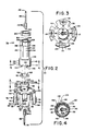
- Fig. 3 is a top plan view of the vial adapter in the reconstitution device illustrated in Fig. 1.
- Fig. 4 is a bottom plan view of the bag adapter utilized in the reconstitution device of Fig. 1.
- Fig. 5 is a cross-sectional view of the reconstitution device with the valve closed and illustrating attachment of the device to both the liquid container and the drug container.
- Fig. 6 is a cross-sectional view like Fig. 5, but with the valve open.
- Fig. 7 is a cross-sectional view of a modified device with the bag adapter disposed relative to the needle so that the needle has not yet totally pierced the injection site on the bag.
- Figs. 1 to 7 there is illustrated various embodiments of the reconstitution device and system of the present invention.
- Figs. 1 through 6 a first embodiment of the reconstitution device and system of the present invention.
- Fig. 1 illustrates a reconstitution device 30 for securely coupling and permitting selective fluid flow between a first container such as a drug vial 32 and a second container such as a flexible-walled medical liquid container 34.
- the drug vial 32 contains a first component such as a drug 36, shown in powdered form.
- the drug 36 may be in another form, such as a liquid.
- the drug vial 32 may be of standard construction.
- the drug vial is typically made of optically transparent glass, including a mouth 38 with a rubber stopper 40 mounted therein.
- a metal band 42 is mounted about the mouth 38, retaining the rubber stopper 40 within the vial 32.
- the rubber stopper 40 serves as an access site into the interior chamber 44 defined by the vial 32.
- the metal band 42 initially includes a top portion (not shown) covering the top of the rubber stopper 40.
- the top portion is separated from the metal band 42 by means of a weakened score line disposed at inner circle 46 of the metal band 42. The top portion is removed to provide access to the rubber stopper 40.
- the second container 34 as illustrated in Fig. 1 is a flexible walled, compressible medical parenteral solution container of known construction, including two sheets 48, 50 of flexible plastic material sealed together about their peripheries.
- the liquid container 34 includes an administration port 52 and an injection site 54, both forming part of the container 34.
- the administration port 52 includes a plastic tube 56 with a membrane (not shown) of standard construction therein which closes off the administration port 52.
- a spike of a standard intravenous administration set (not shown) is inserted into the tube 56, piercing the membrane and allowing liquid 60 such as dextrose solution, saline solution, water or other fluid in the container 34 to exit the liquid container 34, flow through the administration set and, via vein access means, flow into the intravenous system of a patient.
- the injection site 54 may include an outer tube 62 secured between the two plastic sheets.
- An inner tube 64 having a membrane 66 closing the passage of the inner tube 64 is mounted in and sealed to the outer tube 62. A portion of the inner tube 64 extends out of the outer tube 62.
- the injection site 54 typically includes a polyisoprene or latex situs 68 which is pierceable by a needle and resealable upon withdrawal of the needle.
- the situs includes a skirt 70 which grips the outer surface 72 of the inner tube 64.
- the situs 68 may be secured to the inner tube 64 by means of a shrink band 74 conforming to the outer surface 72 of the inner tube 64 and to the skirt 70 of the situs 68.
- the reconstitution device 30 includes means for securing the device to the first container such as the drug container 32 and means for securing the device to the second container such as the liquid container 34.
- the drug container securing means is noted generally by vial adapter 76.
- the liquid container securing means is noted generally by bag adapter 78.
- the vial adapter 76 is secured over the mouth 38 of the drug vial 32.
- the bag adapter 78 is secured over the situs 68 and inner tube 64 of the injection site 54.
- the separate parts of the reconstitution device 30 include the vial adapter 76, a sealing segment 80, a first flow path means segment such as first needle 82, the bag adapter 78, a second flow path means segment such as a second needle 84, and a locking ring 160.
- the vial adapter 76 includes base means such as a generally circular base 88.
- a vial adapter skirt 90 extends away from the base 88.
- the vial adapter skirt 90 may be constructed of a single wall portion, two wall portions are better and in the preferred embodiments of the invention the vial adapter skirt 90 is formed by four upstanding wall portions 92.
- Each wall portion 92 includes a top 94 opposite the base 88.
- a ridge 96 extends inwardly from an inside wall 98 of at least one and preferably all of the wall portions 92, near the top 94 thereof.
- the ridge or ridges 96 can be made to extend inwardly a great distance if required, as explained further below.
- the ridges 96 snap into the underside 43 of the vial mouth 38 to create a mechanical interlock, securing the vial adapter 76 to the vial 32, as seen in Fig. 5.
- Wall slots 100 are disposed in each of the wall portions 92 having an annular ridge 96. Each of the wall slots 100 extend from the base 88 to an annular ridge 96. The wall portions 92 are spaced from each other to permit bending of the wall portions toward and away from each other as will be explained further below.
- the vial adapter 76 includes a stem 102 extending from the center of the base 88.
- the stem is substantially cylindrical.
- a cylindrical opening 104 extends through the stem 102 and base 88.
- the stem 102 has a flange 106 extending about the circumference of the upper portion of the stem 102.
- a stem channel 108 is disposed in and open to the top 110 of the stem 102.
- the stem channel 108 communicates with the cylindrical opening 104.
- the first needle 82 is mounted within the cylindrical opening 104 of the stem 102.
- the first needle 82 includes annular barbs 112 extending near the blunt end 114 of the needle 82 to allow for a tight force-fit attachment of the first needle 82 to the vial adapter 76.
- Other means of attachment are of course possible, such as by the use of adhesives.
- the first needle 82 includes a pointed end 116 opposite the blunt end 114. The first needle 82 is long enough such that when the vial adapter 76 is secured about the mouth 38 of a drug vial 32, the pointed end 116 has completely pierced the rubber stopper 40 or other access site.
- the pointed end 116 extends past the inner ledge 118 of the annular ridges 96 but does not extend to the tops 94 of the wall portions 92.
- the first needle 82 is thus somewhat recessed to avoid harm to the operator.
- the first needle 82 extends generally parallel with the vial adapter skirt 90.
- the sealing segment 80 is mounted to the top 110 of the stem 102.
- the sealing segment 80 is in the preferred embodiment a resilient material such as silicone rubber or other elastomer.
- the sealing segment 80 includes an aperture 120 and an attachment aperture 122.
- the sealing segment 80 is mounted to the vial adapter 76 by mounting the attachment aperture 122 over a stem post 124 extending from the top 110 of the stem 102.
- the stem post 124 through the attachment aperture 122, keeps the sealing segment 80 stationary relative to the stem 102.
- the aperture 120 is disposed such that it is in alignment with the stem channel 108, which itself is in communication with the inside of the first needle 82 at the blunt end 114 thereof.
- the sealing segment 80 may be secured to the stem 102 by other means, such as by the use of adhesive or solvent, but it is medically desirable as a general rule to minimize contact of solvents and adhesives with medical solutions; hence the mechanical interfitment of the stem post 124 and the sealing segment 80.
- the bag adapter 78 is mounted about the stem 102 of the vial adapter 76.
- the bag adapter 78 includes base means such as a base segment 126.
- the base segment 126 includes a base segment cylindrical opening 128 extending therethrough, in which is mounted the second needle 84.
- the second needle 84 may be of the same construction as the first needle 82, including a blunt end 130 and a pointed end 132 opposite the blunt end 130. Annular barbs 134 extend from the second needle 84 near the blunt end 130 to permit a tight force fit within the base segment cylindrical opening 128.
- the needles 82, 84 are made of stainless steel in the preferred embodiment.
- a base segment channel 136 is disposed in and open to the stem facing side 138 of the base segment 126.
- the base segment channel 136 is in open communication with the inside of the second needle 84 through the blunt end 130.
- a rim 140 extends generally parallel with the axis of the second needle 84, from the stem facing side 138 of the base segment 126.
- the rim 140 includes a small lip 142 extending inwardly from the rim 140 near the rim edge 144.
- the bag adapter 78 is rotatably mounted on the vial adapter 76 during manufacture by fitting the rim 140 over the stem 102.
- the lip 142 on the rim 140 and the flange 106 on the stem 102 retain the bag adapter 78 on the vial adapter 76.
- the rim 140 includes a cut out portion 146 around a portion of the circumference of the rim 140, open at the rim edge 144. This cut out portion 146 is aligned with a base post 148 which extends from the base 88 of the vial adapter 76 when the vial and bag adapters 76, 78 are assembled during manufacture of the reconstitution device 30.
- the cut out portion 146 in the rim 140 is partly defined by open position side edge 150 and closed position side edge 152, so named because of their operation in the valve means, explained below.
- Rotation of the bag adapter 78 relative to the vial adapter 76 is limited by the base post 148 which serves as a stop against the open position side edge 150 in one direction and against the closed position side edge 152 in the opposite direction.
- the valve means includes the stem channel 108, the base segment channel 136, the sealing segment 80, the base post 148 and the cut out portion 146 of the rim 140.
- side edge 152 is adjacent the base post 148, the valve is closed.
- the base segment channel 136 in open communication with the blunt end 130 of the second needle 84 and open at the stem facing side 138 of the base segment 126, abuts the resilient sealing segment 80, thereby preventing fluid flow into or out of the blunt end 130 of the second needle 84.
- the valve When the bag adapter 78 is rotated relative to the vial adapter 76 such that the open position side edge 150 is adjacent to the base post 148, the valve is in the open position, as seen in Fig. 6.
- the base segment channel 136 opens to the aperture 120 in the sealing segment 80, the aperture already being aligned with the stem channel 108.
- the first and second needles 82, 84 are now in open communication through the blunt end 130, the base segment channel 136, the aperture 120, the stem channel 108 and the blunt end 114.
- the pointed end 116 of the first needle 82 comprises the drug container piercing means for piercing the access site of the drug container which in this case is the rubber stopper 40.
- the pointed end 132 of the second needle 84 comprises the liquid container piercing means for piercing the injection site 54 of the liquid container 34.
- the bag adapter 78 further includes at least two, and in the preferred embodiment four wall segments 154 extending from the base segment 126, opposite the rim 140 and substantially parallel with the axis of the second needle 84.
- the wall segments 154 define a volume having a generally cylindrical shape.
- the wall segments 154 are disposed around and spaced from the second needle 84 portion of the flow path means.
- a retaining projection 156 extends inwardly from near the top 158 of at least one and preferably all of the wall segments 154.
- the bag adapter 78 further includes a locking ring 160 which may be made of plastic, slidably mounted about the exterior 162 of the wall segments 154.
- the locking ring 160 is disposed for sliding movement over the wall segments 154. In a first direction, movement of the locking ring 160 is limited by a step 164 of the base segment 126. In the opposite direction, movement of the locking ring 160 is limited by a distal step 166 extending around the exterior 162 of the wall segments near the top 158 thereof, near the retaining projections 156.
- the operator slides the locking ring 160 from a first position where the locking ring 160 abuts the step 164 (Fig. 1) to a second position near or abutting the distal step 166 (Fig. 5).
- the inside diameter of the locking ring 160 may be greater than, equal to, or less than the outside diameter defined by the exterior 162 of the wall segments.
- the wall segments 154 flex inwardly and outwardly.
- the injection site 54 including the inner tube 64, may flex the wall segments 154 outwardly even after the retaining projections 156 are past the situs 68, thereby limiting movement of the locking ring 160 to a second position which is further away from the distal step 166.
- the locking ring 160 When the locking ring 160 is in the second position it urges the wall segments 154 inwardly, against the injection site 54, including the outer tube 62.
- An interlock between the retaining projections 156 and the injection site 54 is created because the locking ring creates sufficient pressure against the wall segments 154 and retaining projections 156, and thus the outer tube 62 so that axial movement of the bag adapter 78 relative to the injection site 54 is very difficult in either direction.
- Prevention of axial movement when the locking ring is in the second position may be facilitated by the high coefficient of friction typically associated with the soft plastic typically used for the inner and outer tubes 62, 64 of the injection site.
- the bag adapter 78 with locking ring 160 may be designed to fit so tightly on the injection site 54 that the retaining projections 156 indent the outer tube 62, creating more than a friction fit.
- the device 30 and injection site 54 may alternatively be sized and positioned so that the retaining projections 156 are never intended to be mounted about the outer tube 62.
- the retaining projections exert pressure against the inner tube 64, just past the bottom edge 71 of the skirt 70.
- the reconstitution device is typically first attached to the drug vial 32, by pushing the first needle 82 through the rubber stopper 40, simultaneously urging the wall portions 92 of the vial adapter skirt 90 over the mouth 38 of the vial including the metal band 42. Because in the preferred embodiment a plurality of wall portions 92 are used, the wall portions can be sized for an extremely tight fit with the vial 32. The wall portions 92 flex outwardly until the ridges 96 pass the metal band 42; the wall portions 92, including the ridges 96 then snap inwardly. Removal of the vial adapter 76 is prevented by the inner ledge 118 of the ridges 96 engaging the under side 43 of the metal band 42.
- the valve is in the closed position.
- the operator for example a hospital pharmacist, then attaches the reconstitution device 30 to the parenteral solution container 34.
- the operator first ensures that the locking ring 160 is in the first position.
- the second needle 84 is inserted through the situs 68 and membrane 66 within the inner tube 64.
- the wall segments 154 of the bag adapter 78 are urged over the skirt 70 and the outside of the inner tube 64, until the retaining projections 156 on the wall segments pass the bottom edge 71 of the skirt and, depending on the length of the outer tube 62, onto the outer tube 62 as illustrated.
- the pharmacist may then choose to open the valve by rotating the rim 140 around the stem 102 until the open position side edge 150 of the cut out portion 146 abuts the base post 148.
- the first and second needles of the flow path means are now in open communication.
- the interior chamber 44 of the drug vial 32 and the interior chamber 45 of the liquid container 34 are also in open communication.
- the drug may then be reconstituted in the known manner, by variously squeezing liquid and air from the liquid container 34 into the drug vial 32.
- the reconstitution device 30, the drug vial 32 and the liquid container 34 together form a reconstitution system which need not be disconnected.
- the parenteral solution container 34, with the reconstitution device 30 and vial 32 still attached, may be connected to an intravenous administration set at the administration port 52 as previously described and then hung from an equipment pole to deliver the solution through the set to a patient's venous system. After the contents of the liquid container (now containing both the liquid 60 and the drug 36) have been delivered, the entire reconstitution system 168 may be thrown away.
- the reconstitution device 30 and the reconstitution system 168 provide several distinct advantages. Since the liquid container securing means and drug container securing means both include interlocks, as opposed to only friction fits, inadvertent removal of the vial and bag adapters 76, 78 is prevented. If desired the reconstitution device may be left attached to the bag 34 as well as to the vial 32. Thus, hospital personnel, such as the pharmacist and nurse, are not exposed at all to the drugs themselves, which may be hazardous to hospital personnel upon repeated exposure. This exposure previously existed with prior art devices due to, for example, small amounts of liquid staying on exposed needle tips.
- the reconstitution device 170 may be like the reconstitution device 30 except that the length of the wall segments 172 and the second needle 174 are sized so that installation of the bag adapter 176 about a container injection site 54 does not automatically place the liquid 60 within the container 34 in communication with the second needle 174.
- the retaining projections 178 extending from the wall segments 172 reach the outer tube 62, the pointed end 180 of the second needle 174 will have pierced the situs 68 but will not have pierced the membrane 66.
- the reconstitution device may be kept in this position by sliding the locking ring 182 into the second position.
- the operator wishes to reconstitute the drug 36 he or she may slide the locking ring 182 to the first position and then urge the reconstitution device 170 an additional distance over the injection site 54, along the outer tube 62.
- the situs 68 abuts the base 184 of the bag adapter 176, the second needle 174 will have already pierced the membrane 66.
- the operator may then once more slide the locking ring 182 into the second position, once more stabilizing the axial relationship between the injection site and the reconstitution device.
Abstract
Description
- The reconstitution device of the present invention is directed to the proper mixing of one substance with another and is particularly directed to the medical field for the reconstitution of a drug by a diluent.
- Many drugs are mixed with a diluent before being delivered intravenously to a patient. The diluent may be for example a dextrose solution, a saline solution or even water. Many such drugs are supplied in powder form and packaged in glass vials. Other drugs, such as some used in chemotherapy, are packaged in glass vials in a liquid state.
- In order for powdered drugs to be given intravenously to a patient, the drugs must first be placed in liquid form. Other drugs, although in a liquid state, must be still be diluted before administration to a patient. In this specification, reconstitution also includes dilution.
- One way of reconstituting a powdered drug is to first inject the liquid diluent into the drug vial. This may be performed by means of a combination syringe and syringe needle having diluent therein. After the rubber stopper of the drug vial is pierced by the needle, liquid in the syringe is injected into the vial. The vial is shaken to mix the powdered drug with the liquid. The liquid is then withdrawn back into the syringe. The steps may be repeated several times. The syringe is withdrawn. The drug may then be injected into a patient.
- Another common means of drug administration is to inject the reconstituted drug in the syringe into a parenteral solution container, such as a Minibag™ flexible parenteral solution container or Viaflex® flexible parenteral solution container sold by Travenol Laboratories of Deerfield, Illinois, a wholly owned subsidiary of the assignee of the present invention. These containers may already have therein dextrose or saline solution, for example. The drug, now mixed with the solution in the parenteral solution container, is delivered through an intravenous solution administration set to a vein access site of the patient.
- Another means for reconstituting a powdered drug utilizes a reconstitution device sold by Travenol Laboratories, product code No. 2B8064. That device includes a double pointed needle and guide tubes mounted around both ends of the needle. This prior art reconstitution device is utilized to place the drug vial in flow communication with a flexible walled parenteral solution container for example. Once the connection is made, liquid in the solution container may be forced into the drug vial by squeezing the solution container. The vial is then shaken. The liquid in the vial is withdrawn by squeezing air from the solution container into the vial. When compression of the flexible-walled solution container is stopped, the pressurized air in the vial acts as a pump to force the liquid in the vial back into the solution container.
- Another form of reconstitution device is seen in U.S. Patent No. 3,976,073 to Quick et al., assigned to the assignee of the present invention. Yet another type of reconstitution system is disclosed in U.S. Patent No. 4,328,802 to Curley et al., entitled "Wet Dry Syringe Package" which includes a vial adapter having inwardly directed retaining projections to firmly grip the retaining cap lip of a drug vial to secure the vial to the vial adapter. The package disclosed in Curley is directed to reconstituting a drug by means of a syringe.
- Other means for reconstituting a drug are shown for example in U.S. Patent Nos. 4,410,321 to Pearson et al., entitled "Closed Drug Delivery System"; 4,411,662 to Pearson and 4,432,755 to Pearson, both entitled "Sterile Coupling;" and 4,458,733 to Lyons, entitled "Mixing Apparatus", all assigned to the assignee of the present invention.
- With respect to those situations where it is desired to combine a drug in a drug vial with the liquid in a separate parenteral solution container, all without need for an intermediary syringe, there have been up until now several problems which are typically aggravated in a hospital environment, with many patients. First, many drugs are packaged in a powdered state in drug vials separate from a diluent because in the presence of moisture drug efficacy in some cases is maintained for less than twenty-four hours. Once the drug is reconstituted, the solution container with the drug therein must be used in a relatively short time period. Patient prescriptions are often changed after the drug is reconstituted by, for example, the hospital pharmacist. If a prescription is changed, the reconstituted drug and the diluent will most likely be wasted because they must be used in a short time period.
- Another problem associated with drug reconstitution is that some drugs, e.g., some chemotherapy drugs, may be hazardous to hospital personnel who are repeatedly exposed to the drugs over long time periods. Use of any reconstitution means which uses separate drug and diluent containers will likely result in exposure of personnel to the drug. A common source of exposure is small volumes of the drug/diluent mixture which may drip from the needle utilized to reconstitute the drug.
- The pre-characterising part of Claim 1 is based on the reconstitution device sold by Travenol Laboratories under product code no. 2B8064. This device comprises a double-pointed needle for puncturing pierceable injection sites of a drug container and flexible-walled liquid container respectively, to bring them into fluid communication. Guide tubes around the needles engage the containers to guide the needles, as the needles and containers are push-fitted into engagement.
The distinguishing features of the invention are as set out in the characterising part of Claim 1. - US-A-3809289 describes a device which is screw-engageable with two containers and has cutting means for cutting closure membranes of the containers during such screw engagement.
- US-A-4146153 describes a flexible-walled container having an adaptor screw-mounted on a port of the container. The port is closed by a membrane which can be cut by a hollow spike during screw-rotation of the adaptor. The adaptor includes a needle, in fluid communication with the spike, for puncturing a closure membrane of a second container.
- The devices of the present invention solve the problems outlined above. Drug exposure to hospital personnel is minimized or eliminated. Drug labeling, to ensure that the proper drug is administered to the correct patient, is made unnecessary by means of a reconstitution device that is securely retained on both the parenteral solution container and the drug vial, preventing inadvertent separation of the vial from the solution container. Determination of what drug has been mixed in a specific solution container can be made simply by looking at the pre-existing label on the attached drug vial.
- In one embodiment, the device of the present invention includes valve means to prevent communication between the drug and the diluent until just before use, even though the solution container and the drug vial have been previously coupled by the device, thus facilitating a longer time period between the time of coupling and drug infusion.
- Fig. 1 is an exploded perspective view of one embodiment of the invention, including valve means, illustrating attachment of the reconstitution device to a flexible walled liquid container and to a drug vial container to form a reconstitution system.
- Fig. 2 is an exploded view of the reconstitution device illustrated in Fig. 1.
- Fig. 3 is a top plan view of the vial adapter in the reconstitution device illustrated in Fig. 1.
- Fig. 4 is a bottom plan view of the bag adapter utilized in the reconstitution device of Fig. 1.
- Fig. 5 is a cross-sectional view of the reconstitution device with the valve closed and illustrating attachment of the device to both the liquid container and the drug container.
- Fig. 6 is a cross-sectional view like Fig. 5, but with the valve open.
- Fig. 7 is a cross-sectional view of a modified device with the bag adapter disposed relative to the needle so that the needle has not yet totally pierced the injection site on the bag.
- Referring generally to Figs. 1 to 7, there is illustrated various embodiments of the reconstitution device and system of the present invention. There is particularly illustrated in Figs. 1 through 6 a first embodiment of the reconstitution device and system of the present invention. Fig. 1 illustrates a
reconstitution device 30 for securely coupling and permitting selective fluid flow between a first container such as adrug vial 32 and a second container such as a flexible-walledmedical liquid container 34. Thedrug vial 32 contains a first component such as adrug 36, shown in powdered form. Thedrug 36 may be in another form, such as a liquid. - The
drug vial 32 may be of standard construction. The drug vial is typically made of optically transparent glass, including amouth 38 with arubber stopper 40 mounted therein. Ametal band 42 is mounted about themouth 38, retaining therubber stopper 40 within thevial 32. Therubber stopper 40 serves as an access site into theinterior chamber 44 defined by thevial 32. - Typically, the
metal band 42 initially includes a top portion (not shown) covering the top of therubber stopper 40. The top portion is separated from themetal band 42 by means of a weakened score line disposed atinner circle 46 of themetal band 42. The top portion is removed to provide access to therubber stopper 40. - The
second container 34, as illustrated in Fig. 1 is a flexible walled, compressible medical parenteral solution container of known construction, including twosheets liquid container 34 includes anadministration port 52 and aninjection site 54, both forming part of thecontainer 34. In the illustratedcontainer 34, theadministration port 52 includes aplastic tube 56 with a membrane (not shown) of standard construction therein which closes off theadministration port 52. Typically, a spike of a standard intravenous administration set (not shown) is inserted into thetube 56, piercing the membrane and allowing liquid 60 such as dextrose solution, saline solution, water or other fluid in thecontainer 34 to exit theliquid container 34, flow through the administration set and, via vein access means, flow into the intravenous system of a patient. Theinjection site 54 may include anouter tube 62 secured between the two plastic sheets. Aninner tube 64 having amembrane 66 closing the passage of theinner tube 64 is mounted in and sealed to theouter tube 62. A portion of theinner tube 64 extends out of theouter tube 62. - The
injection site 54 typically includes a polyisoprene orlatex situs 68 which is pierceable by a needle and resealable upon withdrawal of the needle. The situs includes askirt 70 which grips theouter surface 72 of theinner tube 64. Thesitus 68 may be secured to theinner tube 64 by means of ashrink band 74 conforming to theouter surface 72 of theinner tube 64 and to theskirt 70 of thesitus 68. - The
reconstitution device 30 includes means for securing the device to the first container such as thedrug container 32 and means for securing the device to the second container such as theliquid container 34. The drug container securing means is noted generally byvial adapter 76. The liquid container securing means is noted generally bybag adapter 78. Thevial adapter 76 is secured over themouth 38 of thedrug vial 32. Thebag adapter 78 is secured over thesitus 68 andinner tube 64 of theinjection site 54. - Referring to Figs. 2 through 6 and especially Fig. 2, the separate parts of the
reconstitution device 30 include thevial adapter 76, a sealingsegment 80, a first flow path means segment such asfirst needle 82, thebag adapter 78, a second flow path means segment such as asecond needle 84, and alocking ring 160. - The
vial adapter 76 includes base means such as a generallycircular base 88. Avial adapter skirt 90 extends away from thebase 88. Although thevial adapter skirt 90 may be constructed of a single wall portion, two wall portions are better and in the preferred embodiments of the invention thevial adapter skirt 90 is formed by fourupstanding wall portions 92. Eachwall portion 92 includes a top 94 opposite thebase 88. Aridge 96 extends inwardly from aninside wall 98 of at least one and preferably all of thewall portions 92, near the top 94 thereof. The ridge orridges 96 can be made to extend inwardly a great distance if required, as explained further below. Theridges 96 snap into theunderside 43 of thevial mouth 38 to create a mechanical interlock, securing thevial adapter 76 to thevial 32, as seen in Fig. 5. -
Wall slots 100 are disposed in each of thewall portions 92 having anannular ridge 96. Each of thewall slots 100 extend from the base 88 to anannular ridge 96. Thewall portions 92 are spaced from each other to permit bending of the wall portions toward and away from each other as will be explained further below. - The
vial adapter 76 includes astem 102 extending from the center of thebase 88. The stem is substantially cylindrical. Acylindrical opening 104 extends through thestem 102 andbase 88. Thestem 102 has aflange 106 extending about the circumference of the upper portion of thestem 102. - A
stem channel 108 is disposed in and open to the top 110 of thestem 102. Thestem channel 108 communicates with thecylindrical opening 104. - The
first needle 82 is mounted within thecylindrical opening 104 of thestem 102. In the preferred embodiment thefirst needle 82 includesannular barbs 112 extending near theblunt end 114 of theneedle 82 to allow for a tight force-fit attachment of thefirst needle 82 to thevial adapter 76. Other means of attachment are of course possible, such as by the use of adhesives. Thefirst needle 82 includes apointed end 116 opposite theblunt end 114. Thefirst needle 82 is long enough such that when thevial adapter 76 is secured about themouth 38 of adrug vial 32, thepointed end 116 has completely pierced therubber stopper 40 or other access site. In the preferred embodiment, thepointed end 116 extends past theinner ledge 118 of theannular ridges 96 but does not extend to the tops 94 of thewall portions 92. Thefirst needle 82 is thus somewhat recessed to avoid harm to the operator. Thefirst needle 82 extends generally parallel with thevial adapter skirt 90. - The sealing
segment 80 is mounted to the top 110 of thestem 102. The sealingsegment 80 is in the preferred embodiment a resilient material such as silicone rubber or other elastomer. The sealingsegment 80 includes anaperture 120 and anattachment aperture 122. The sealingsegment 80 is mounted to thevial adapter 76 by mounting theattachment aperture 122 over astem post 124 extending from the top 110 of thestem 102. Thestem post 124, through theattachment aperture 122, keeps the sealingsegment 80 stationary relative to thestem 102. Theaperture 120 is disposed such that it is in alignment with thestem channel 108, which itself is in communication with the inside of thefirst needle 82 at theblunt end 114 thereof. - The sealing
segment 80 may be secured to thestem 102 by other means, such as by the use of adhesive or solvent, but it is medically desirable as a general rule to minimize contact of solvents and adhesives with medical solutions; hence the mechanical interfitment of thestem post 124 and the sealingsegment 80. - The
bag adapter 78 is mounted about thestem 102 of thevial adapter 76. Thebag adapter 78 includes base means such as abase segment 126. Thebase segment 126 includes a base segmentcylindrical opening 128 extending therethrough, in which is mounted thesecond needle 84. Thesecond needle 84 may be of the same construction as thefirst needle 82, including ablunt end 130 and apointed end 132 opposite theblunt end 130.Annular barbs 134 extend from thesecond needle 84 near theblunt end 130 to permit a tight force fit within the base segmentcylindrical opening 128. Theneedles - A
base segment channel 136 is disposed in and open to thestem facing side 138 of thebase segment 126. Thebase segment channel 136 is in open communication with the inside of thesecond needle 84 through theblunt end 130. - A
rim 140 extends generally parallel with the axis of thesecond needle 84, from thestem facing side 138 of thebase segment 126. Therim 140 includes asmall lip 142 extending inwardly from therim 140 near therim edge 144. Thebag adapter 78 is rotatably mounted on thevial adapter 76 during manufacture by fitting therim 140 over thestem 102. Thelip 142 on therim 140 and theflange 106 on thestem 102 retain thebag adapter 78 on thevial adapter 76. - The
rim 140 includes a cut outportion 146 around a portion of the circumference of therim 140, open at therim edge 144. This cut outportion 146 is aligned with abase post 148 which extends from thebase 88 of thevial adapter 76 when the vial andbag adapters reconstitution device 30. - The cut out
portion 146 in therim 140 is partly defined by openposition side edge 150 and closedposition side edge 152, so named because of their operation in the valve means, explained below. Rotation of thebag adapter 78 relative to thevial adapter 76 is limited by thebase post 148 which serves as a stop against the openposition side edge 150 in one direction and against the closedposition side edge 152 in the opposite direction. - The valve means includes the
stem channel 108, thebase segment channel 136, the sealingsegment 80, thebase post 148 and the cut outportion 146 of therim 140. When the closedposition side edge 152 is adjacent thebase post 148, the valve is closed. In this position the inside of the first andsecond needles base segment channel 136, in open communication with theblunt end 130 of thesecond needle 84 and open at thestem facing side 138 of thebase segment 126, abuts theresilient sealing segment 80, thereby preventing fluid flow into or out of theblunt end 130 of thesecond needle 84. - When the
bag adapter 78 is rotated relative to thevial adapter 76 such that the openposition side edge 150 is adjacent to thebase post 148, the valve is in the open position, as seen in Fig. 6. Here thebase segment channel 136 opens to theaperture 120 in the sealingsegment 80, the aperture already being aligned with thestem channel 108. The first andsecond needles blunt end 130, thebase segment channel 136, theaperture 120, thestem channel 108 and theblunt end 114. These elements, along with the remainder of the first andsecond needles reconstitution device 30. Thepointed end 116 of thefirst needle 82 comprises the drug container piercing means for piercing the access site of the drug container which in this case is therubber stopper 40. Thepointed end 132 of thesecond needle 84 comprises the liquid container piercing means for piercing theinjection site 54 of theliquid container 34. - The
bag adapter 78 further includes at least two, and in the preferred embodiment fourwall segments 154 extending from thebase segment 126, opposite therim 140 and substantially parallel with the axis of thesecond needle 84. Thewall segments 154 define a volume having a generally cylindrical shape. Thewall segments 154 are disposed around and spaced from thesecond needle 84 portion of the flow path means. A retainingprojection 156 extends inwardly from near the top 158 of at least one and preferably all of thewall segments 154. When thesecond needle 84 is urged into theliquid container 34 by piercing theinjection site 54, thewall segments 154 surround thesitus skirt 70 as well as theshrink band 74. - The
bag adapter 78 further includes alocking ring 160 which may be made of plastic, slidably mounted about theexterior 162 of thewall segments 154. Thelocking ring 160 is disposed for sliding movement over thewall segments 154. In a first direction, movement of thelocking ring 160 is limited by astep 164 of thebase segment 126. In the opposite direction, movement of thelocking ring 160 is limited by adistal step 166 extending around theexterior 162 of the wall segments near the top 158 thereof, near the retainingprojections 156. - Once the
reconstitution device 30 has been secured to theinjection site 54, with the needle having pierced thesitus 68, the operator slides thelocking ring 160 from a first position where thelocking ring 160 abuts the step 164 (Fig. 1) to a second position near or abutting the distal step 166 (Fig. 5). Depending on the dimensional relationships of theinjection site 54 of thecontainer 34 andwall segments 154, the inside diameter of thelocking ring 160 may be greater than, equal to, or less than the outside diameter defined by theexterior 162 of the wall segments. Thewall segments 154 flex inwardly and outwardly. If large enough, theinjection site 54, including theinner tube 64, may flex thewall segments 154 outwardly even after the retainingprojections 156 are past thesitus 68, thereby limiting movement of thelocking ring 160 to a second position which is further away from thedistal step 166. - When the
locking ring 160 is in the second position it urges thewall segments 154 inwardly, against theinjection site 54, including theouter tube 62. An interlock between the retainingprojections 156 and theinjection site 54 is created because the locking ring creates sufficient pressure against thewall segments 154 and retainingprojections 156, and thus theouter tube 62 so that axial movement of thebag adapter 78 relative to theinjection site 54 is very difficult in either direction. Prevention of axial movement when the locking ring is in the second position may be facilitated by the high coefficient of friction typically associated with the soft plastic typically used for the inner andouter tubes bag adapter 78 with lockingring 160 may be designed to fit so tightly on theinjection site 54 that the retainingprojections 156 indent theouter tube 62, creating more than a friction fit. - Furthermore, if an axial removal force causes the retaining projections to slide off the
outer tube 62 and onto theinner tube 64, the retaining projections are stopped by and create an interlock with thebottom edge 71 of theskirt 70. - The
device 30 andinjection site 54 may alternatively be sized and positioned so that the retainingprojections 156 are never intended to be mounted about theouter tube 62. Upon installation of thebag adapter 78 on thecontainer 34 the retaining projections exert pressure against theinner tube 64, just past thebottom edge 71 of theskirt 70. - In operation, the reconstitution device is typically first attached to the
drug vial 32, by pushing thefirst needle 82 through therubber stopper 40, simultaneously urging thewall portions 92 of thevial adapter skirt 90 over themouth 38 of the vial including themetal band 42. Because in the preferred embodiment a plurality ofwall portions 92 are used, the wall portions can be sized for an extremely tight fit with thevial 32. Thewall portions 92 flex outwardly until theridges 96 pass themetal band 42; thewall portions 92, including theridges 96 then snap inwardly. Removal of thevial adapter 76 is prevented by theinner ledge 118 of theridges 96 engaging the underside 43 of themetal band 42. - Typically, at this point during use the valve is in the closed position. The operator, for example a hospital pharmacist, then attaches the
reconstitution device 30 to theparenteral solution container 34. The operator first ensures that thelocking ring 160 is in the first position. Thesecond needle 84 is inserted through thesitus 68 andmembrane 66 within theinner tube 64. Simultaneously, thewall segments 154 of thebag adapter 78 are urged over theskirt 70 and the outside of theinner tube 64, until the retainingprojections 156 on the wall segments pass thebottom edge 71 of the skirt and, depending on the length of theouter tube 62, onto theouter tube 62 as illustrated. The operator then slides thelocking ring 160 into the second position, forcing the retainingprojections 156 inwardly and creating an interlock between the retainingprojections 156 on the wall segments and theouter tube 62,inner tube 64 andbottom edge 71 of the skirt, thereby preventing removal of thebag adapter 78 from theinjection site 54. - Depending on the drug and the hospital procedure, the pharmacist may then choose to open the valve by rotating the
rim 140 around thestem 102 until the openposition side edge 150 of the cut outportion 146 abuts thebase post 148. The first and second needles of the flow path means are now in open communication. Thus, theinterior chamber 44 of thedrug vial 32 and the interior chamber 45 of theliquid container 34 are also in open communication. The drug may then be reconstituted in the known manner, by variously squeezing liquid and air from theliquid container 34 into thedrug vial 32. - The
reconstitution device 30, thedrug vial 32 and theliquid container 34 together form a reconstitution system which need not be disconnected. Theparenteral solution container 34, with thereconstitution device 30 andvial 32 still attached, may be connected to an intravenous administration set at theadministration port 52 as previously described and then hung from an equipment pole to deliver the solution through the set to a patient's venous system. After the contents of the liquid container (now containing both the liquid 60 and the drug 36) have been delivered, the entire reconstitution system 168 may be thrown away. - The
reconstitution device 30 and the reconstitution system 168 provide several distinct advantages. Since the liquid container securing means and drug container securing means both include interlocks, as opposed to only friction fits, inadvertent removal of the vial andbag adapters bag 34 as well as to thevial 32. Thus, hospital personnel, such as the pharmacist and nurse, are not exposed at all to the drugs themselves, which may be hazardous to hospital personnel upon repeated exposure. This exposure previously existed with prior art devices due to, for example, small amounts of liquid staying on exposed needle tips. - By creating an effectively integral system, the need for liquid container relabeling is totally eliminated. Once the hospital pharmacist has connected the reconstitution system 168, the
vial 32, complete with thevial label 33 describing the drug, will be kept with theliquid container 34. The doctor or nurse will know exactly what drug has been added to the liquid 60 being administered to a patient. - The extent of expensive drug waste is dramatically reduced by the device and system of the present invention. Because the vial and liquid container are securely attached, and because of the valve means, the drug need not be reconstituted immediately after the reconstitution device has been coupled to the liquid container and vial. Thus, as often happens, when there is a change in a patient's prescription the hospital is not left with a reconstituted drug in a solution container which must be used in a relatively short time. Instead, upon learning of a prescription change, hospital personnel can return the reconstitution system 168, with the as yet unreconstituted drug, to the hospital pharmacy where it may be retained for a time period which will hopefully permit the system 168 to be used with another patient having the same drug prescription. Even without the valve means, a reconstitution system is created whereby the liquid need not be immediately forced into the vial because there is not a danger of the system becoming disconnected.
- A second embodiment of the invention is illustrated in Fig. 7. Here, the
reconstitution device 170 may be like thereconstitution device 30 except that the length of thewall segments 172 and thesecond needle 174 are sized so that installation of thebag adapter 176 about acontainer injection site 54 does not automatically place the liquid 60 within thecontainer 34 in communication with thesecond needle 174. In this embodiment, when during installation the retainingprojections 178 extending from thewall segments 172 reach theouter tube 62, thepointed end 180 of thesecond needle 174 will have pierced thesitus 68 but will not have pierced themembrane 66. - The reconstitution device may be kept in this position by sliding the
locking ring 182 into the second position. When the operator wishes to reconstitute thedrug 36 he or she may slide thelocking ring 182 to the first position and then urge thereconstitution device 170 an additional distance over theinjection site 54, along theouter tube 62. When thesitus 68 abuts thebase 184 of thebag adapter 176, thesecond needle 174 will have already pierced themembrane 66. - The operator may then once more slide the
locking ring 182 into the second position, once more stabilizing the axial relationship between the injection site and the reconstitution device.
Claims (9)
- A device for use in reconstituting a drug by providing a connection between a drug container (32), having a pierceable access site (40), and a flexible-walled liquid container (34), having a pierceable injection site (54), the device comprising first and second piercing members (82,84) for piercing the access site and injection site respectively as the containers and the device are push-fitted into engagement, so as to enter the interiors of the respective containers, flow path means (82,84,128,136,120, 108) in the device and interconnecting the piercing members so as to place the containers in open communication, and first and second guide means (76,78) mounted about the flow path means for engaging the containers as the containers and the device are push-fitted together, CHARACTERISED in that the first guide means (76) carries locking means adapted for mechanical locking engagement with the drug container (32) as the device is push-fitted on the drug container, to prevent inadvertent detachment of the device from the drug container, and in that the second guide means (78) comprises one or more wall segments (154) and a locking ring (160) slidably mounted about the wall segment or segments (154), the locking ring being disposed for sliding movement from a first position to a second position, the locking ring urging the wall segment or segments inwardly in the second position for gripping the liquid container, in use, to prevent inadvertent detachment of the reconstitution device from the liquid container.
- The reconstitution device of Claim 1, further including valve means (80,120) for selectively opening said flow path means (82,108,84).
- The reconstitution device of Claim 2, wherein the valve means comprises a sealing segment (80) mounted in the flow path between the piercing members (82,84) and having an aperture (120) therethrough; the first and second guide means (76,78) being relatively rotatable from a closed position, in which said piercing members are not in communication, being separated by said sealing segment, and an open position, in which said piercing members are in open communication, through said aperture (120) in said sealing segment.
- The reconstitution device of any preceding claim, wherein said first guide means comprises base means (88) and at least one upstanding wall portion (92) extending from said base means, and the first locking means is defined by a ridge (96) extending inwardly from an inside wall of the wall portion, near a top (94) of the wall portion, a slot (100) being provided in the wall portion and extending from said base means (88) to said annular ridge (96).
- The reconstitution device of Claim 4, wherein the first guide means comprises at least two said upstanding wall portions (92) spaced from each other to permit bending of said wall portions toward and away from each other.
- The reconstitution device of any preceding claim, wherein said one or more wall segments (154) extend from a base means (126), and at least one retaining projection (156) projects inwardly from said wall segment, or at least one of the wall segments and extends generally coplanar with the axis of a cylinder defined by said one or more wall segments, said projection (156) being tapered from a maximum projection near said base means to a minimum projection opposite said base means.
- The reconstitution device of Claims 6, wherein said second guide means comprises at least two of said wall segments (154) extending from said base means, said wall segments defining a volume having a generally cylindrical shape.
- The reconstitution device of Claims 6 or 7, wherein the first position is near said base means (126) and the second position is near the top of the wall segment or segments.
- A drug reconstitution system comprising a device (30) according to any preceding claim, a first container (32) having an access site (40) pierceable by said first piercing means (82) as the first securing means (76) is push-fitted onto the first container, and a second container (34) which is flexible-walled and includes a self-sealing injection site (54) pierceable by said second piercing means (84) as the second securing means (78) is push-fitted onto the injection site.
Applications Claiming Priority (2)
| Application Number | Priority Date | Filing Date | Title |
|---|---|---|---|
| US06/650,481 US4759756A (en) | 1984-09-14 | 1984-09-14 | Reconstitution device |
| US650481 | 1984-09-14 |
Publications (3)
| Publication Number | Publication Date |
|---|---|
| EP0195018A1 EP0195018A1 (en) | 1986-09-24 |
| EP0195018A4 EP0195018A4 (en) | 1988-01-21 |
| EP0195018B1 true EP0195018B1 (en) | 1991-06-05 |
Family
ID=24609096
Family Applications (1)
| Application Number | Title | Priority Date | Filing Date |
|---|---|---|---|
| EP19850904182 Expired - Lifetime EP0195018B1 (en) | 1984-09-14 | 1985-08-07 | Reconstitution device |
Country Status (7)
| Country | Link |
|---|---|
| US (1) | US4759756A (en) |
| EP (1) | EP0195018B1 (en) |
| JP (1) | JPS62500427A (en) |
| CA (1) | CA1239619A (en) |
| DE (1) | DE3583139D1 (en) |
| NO (1) | NO861899L (en) |
| WO (1) | WO1986001712A1 (en) |
Cited By (6)
| Publication number | Priority date | Publication date | Assignee | Title |
|---|---|---|---|---|
| EP1066812A2 (en) | 1999-07-03 | 2001-01-10 | Fresenius Kabi Deutschland GmbH | Lockable adapter for needle |
| US6379340B1 (en) | 1995-03-20 | 2002-04-30 | Medimop Medical Projects Lts. | Fluid control device |
| USD630732S1 (en) | 2009-09-29 | 2011-01-11 | Medimop Medical Projects Ltd. | Vial adapter with female connector |
| US8070739B2 (en) | 2005-08-11 | 2011-12-06 | Medimop Medical Projects Ltd. | Liquid drug transfer devices for failsafe correct snap fitting onto medicinal vials |
| WO2015058136A1 (en) | 2013-10-18 | 2015-04-23 | Infusion Innovations, Inc. | Fluid transfer devices, systems, and methods for their use in delivering medical fluids |
| US9522098B2 (en) | 2006-05-25 | 2016-12-20 | Bayer Healthcare, Llc | Reconstitution device |
Families Citing this family (270)
| Publication number | Priority date | Publication date | Assignee | Title |
|---|---|---|---|---|
| US5330450A (en) * | 1983-01-24 | 1994-07-19 | Icu Medical, Inc. | Medical connector |
| IE60235B1 (en) * | 1986-09-18 | 1994-06-15 | Kabi Pharmacia Ab | "Connector and disposable assembly utilising said connector" |
| US5295658A (en) * | 1987-04-27 | 1994-03-22 | Vernay Laboratories, Inc. | Medical coupling site including slit reinforcing members |
| US5251873B1 (en) * | 1992-06-04 | 1995-05-02 | Vernay Laboratories | Medical coupling site. |
| USRE33617E (en) * | 1987-07-17 | 1991-06-18 | International Medication Systems Limited | Protected cannula |
| US5324256A (en) * | 1987-07-31 | 1994-06-28 | Lawrence A. Lynn | Apparatus and methods for transferring blood between aspiration assembly and an external container |
| US5178607A (en) * | 1987-07-31 | 1993-01-12 | Lynn Lawrence A | Blood aspiration assembly septum and blunt needle aspirator |
| WO1989006553A2 (en) | 1988-01-25 | 1989-07-27 | Baxter International Inc. | Pre-slit injection site and tapered cannula |
| CA1335167C (en) * | 1988-01-25 | 1995-04-11 | Steven C. Jepson | Pre-slit injection site and associated cannula |
| US5100394A (en) * | 1988-01-25 | 1992-03-31 | Baxter International Inc. | Pre-slit injection site |
| US5964785A (en) | 1988-01-25 | 1999-10-12 | Baxter International Inc. | Bayonet look cannula for pre-slit y-site |
| CA1330412C (en) | 1988-07-08 | 1994-06-28 | Steven C. Jepson | Pre-slit injection site and tapered cannula |
| US5514117A (en) * | 1988-09-06 | 1996-05-07 | Lynn; Lawrence A. | Connector having a medical cannula |
| CA2001732A1 (en) * | 1988-10-31 | 1990-04-30 | Lawrence A. Lynn | Intravenous line coupling device |
| US5156598A (en) * | 1988-12-06 | 1992-10-20 | C. R. Bard, Inc. | Prefilled syringe delivery system |
| US5147324A (en) * | 1988-12-06 | 1992-09-15 | C. R. Bard, Inc. | Prefilled syringe delivery system |
| IE62767B1 (en) | 1989-03-17 | 1995-02-22 | Baxter Int | Pre-slit injection site and tapered cannula |
| US5135492A (en) * | 1989-06-26 | 1992-08-04 | University Of Florida | Arterial/venous fluid transfer system |
| US4997430A (en) * | 1989-09-06 | 1991-03-05 | Npbi Nederlands Produktielaboratorium Voor Bloedtransfusieapparatuur En Infusievloeistoffen B.V. | Method of and apparatus for administering medicament to a patient |
| US4994029A (en) * | 1989-09-12 | 1991-02-19 | David Bull Laboratories Pty. Ltd. | Syringe mixer and injector device |
| US5304163A (en) * | 1990-01-29 | 1994-04-19 | Baxter International Inc. | Integral reconstitution device |
| US5122129A (en) * | 1990-05-09 | 1992-06-16 | Olson Donald J | Sampler coupler device useful in the medical arts |
| US5171214A (en) * | 1990-12-26 | 1992-12-15 | Abbott Laboratories | Drug storage and delivery system |
| US5490848A (en) * | 1991-01-29 | 1996-02-13 | The United States Of America As Represented By The Administrator Of The National Aeronautics And Space Administration | System for creating on site, remote from a sterile environment, parenteral solutions |
| ES1016828Y (en) * | 1991-02-22 | 1992-06-01 | Instituto De Biologia Y Sueroterapia, S.A. | DEVICE FOR THE TRANSFER OF LIQUIDS BETWEEN FLEXIBLE AND ROAD CONTAINERS. |
| US5368586A (en) * | 1991-06-21 | 1994-11-29 | Npbi Nederlands Produktielaboratorium Voor Bloedtransfusieapparatuur En Infusievloeistoffen B.V. | Closure for a drug-vial |
| US5776125A (en) | 1991-07-30 | 1998-07-07 | Baxter International Inc. | Needleless vial access device |
| US5308347A (en) * | 1991-09-18 | 1994-05-03 | Fujisawa Pharmaceutical Co., Ltd. | Transfusion device |
| US5694686A (en) * | 1991-12-18 | 1997-12-09 | Icu Medical, Inc. | Method for assembling a medical valve |
| WO1993011828A1 (en) | 1991-12-18 | 1993-06-24 | Icu Medical, Inc. | Medical valve |
| US5279576A (en) * | 1992-05-26 | 1994-01-18 | George Loo | Medication vial adapter |
| US5501426A (en) * | 1992-06-04 | 1996-03-26 | Vernay Laboratories, Inc. | Medical coupling site valve body |
| US5533708A (en) * | 1992-06-04 | 1996-07-09 | Vernay Laboratories, Inc. | Medical coupling site valve body |
| AU4353093A (en) * | 1992-06-22 | 1994-01-24 | Mary Therese Purcell | A reconstitution device |
| CA2099317C (en) * | 1992-07-08 | 1998-08-18 | Howard S. Berger | Safety syringe with i.v. port access |
| US5345070A (en) * | 1992-09-25 | 1994-09-06 | Cobe Laboratories, Inc. | Radio frequency tubing sealer |
| US5374263A (en) * | 1992-10-13 | 1994-12-20 | Automatic Liquid Packaging | Full withdrawal container and method |
| US5334179A (en) * | 1992-10-16 | 1994-08-02 | Abbott Laboratories | Latching piercing pin for use with fluid vials of varying sizes |
| US5472434A (en) * | 1993-05-14 | 1995-12-05 | Akzo N.V. | Spike retainer system |
| CA2124970A1 (en) * | 1993-06-29 | 1994-12-30 | R. Hayes Helgren | Pointed adapter for blunt entry device |
| US5429614A (en) * | 1993-06-30 | 1995-07-04 | Baxter International Inc. | Drug delivery system |
| AU676566B2 (en) * | 1993-06-30 | 1997-03-13 | Baxter International Inc. | Vial adapter |
| US5397303A (en) * | 1993-08-06 | 1995-03-14 | River Medical, Inc. | Liquid delivery device having a vial attachment or adapter incorporated therein |
| US6146362A (en) * | 1993-08-27 | 2000-11-14 | Baton Development, Inc. | Needleless IV medical delivery system |
| US5833674A (en) * | 1993-08-27 | 1998-11-10 | St. Paul Medical, Inc. | Needleless IV medical delivery system |
| USD382958S (en) * | 1993-12-20 | 1997-08-26 | Wolff Stephen H | Intravenous spike stabilizer cover |
| US5522804A (en) * | 1994-02-15 | 1996-06-04 | Lynn; Lawrence A. | Aspiration, mixing, and injection syringe |
| KR100441231B1 (en) | 1994-06-24 | 2004-10-12 | 아이시유메디칼인코오포레이티드 | Fluid transfer device and method of use |
| EP0692235A1 (en) * | 1994-07-14 | 1996-01-17 | International Medication Systems (U.K.) Ltd. | Mixing & dispensing apparatus |
| US5526853A (en) * | 1994-08-17 | 1996-06-18 | Mcgaw, Inc. | Pressure-activated medication transfer system |
| US5533993A (en) * | 1994-10-05 | 1996-07-09 | International Medication Systems, Limited | Medication injector with protected cannula and Y-site lockout |
| US5569209A (en) | 1994-12-21 | 1996-10-29 | Jemm Tran-Safe Systems, Inc. | Needleless transfer system |
| US5647845A (en) * | 1995-02-01 | 1997-07-15 | Habley Medical Technology Corporation | Generic intravenous infusion system |
| DE19513666C1 (en) * | 1995-04-11 | 1996-11-28 | Behringwerke Ag | Device for bringing together a first liquid and a second solid or liquid component by means of negative pressure under sterile conditions |
| US5766147A (en) * | 1995-06-07 | 1998-06-16 | Winfield Medical | Vial adaptor for a liquid delivery device |
| US5738663A (en) | 1995-12-15 | 1998-04-14 | Icu Medical, Inc. | Medical valve with fluid escape space |
| US5893397A (en) * | 1996-01-12 | 1999-04-13 | Bioject Inc. | Medication vial/syringe liquid-transfer apparatus |
| JP3743875B2 (en) * | 1996-04-17 | 2006-02-08 | 株式会社大塚製薬工場 | Plastic double-ended needle |
| IL118497A (en) * | 1996-05-30 | 2002-08-14 | Travenol Lab Israel Ltd | Fluid sampling apparatus |
| US5993412A (en) * | 1997-05-19 | 1999-11-30 | Bioject, Inc. | Injection apparatus |
| US5957898A (en) | 1997-05-20 | 1999-09-28 | Baxter International Inc. | Needleless connector |
| ATE335518T1 (en) | 1997-05-20 | 2006-09-15 | Baxter Int | NEEDLELESS COUPLING PIECE |
| JP4291506B2 (en) * | 1997-08-22 | 2009-07-08 | デカ・プロダクツ・リミテッド・パートナーシップ | Intravenous drug mixing and injection system, method and cassette |
| US6019750A (en) | 1997-12-04 | 2000-02-01 | Baxter International Inc. | Sliding reconstitution device with seal |
| FR2780878B1 (en) * | 1998-07-10 | 2000-09-29 | Frederic Senaux | SNAP-ON TRANSFER CAP |
| GB2339773A (en) * | 1998-07-17 | 2000-02-09 | Galen Ltd | Vial connector system |
| US7074216B2 (en) | 1998-09-15 | 2006-07-11 | Baxter International Inc. | Sliding reconstitution device for a diluent container |
| US6113583A (en) | 1998-09-15 | 2000-09-05 | Baxter International Inc. | Vial connecting device for a sliding reconstitution device for a diluent container |
| AR021220A1 (en) | 1998-09-15 | 2002-07-03 | Baxter Int | CONNECTION DEVICE FOR ESTABLISHING A FLUID COMMUNICATION BETWEEN A FIRST CONTAINER AND A SECOND CONTAINER. |
| US7425209B2 (en) * | 1998-09-15 | 2008-09-16 | Baxter International Inc. | Sliding reconstitution device for a diluent container |
| FR2783808B1 (en) * | 1998-09-24 | 2000-12-08 | Biodome | CONNECTION DEVICE BETWEEN A CONTAINER AND A CONTAINER AND READY-TO-USE ASSEMBLY COMPRISING SUCH A DEVICE |
| US6126618A (en) * | 1999-01-14 | 2000-10-03 | Baxter International Inc. | Apparatus for obtaining liquid samples |
| USD427308S (en) * | 1999-01-22 | 2000-06-27 | Medimop Medical Projects Ltd. | Vial adapter |
| US6245056B1 (en) * | 1999-02-12 | 2001-06-12 | Jack M. Walker | Safe intravenous infusion port injectors |
| FR2790749B1 (en) * | 1999-03-10 | 2001-05-18 | Maco Pharma Sa | DEVICE FOR TRANSFERRING A SUBSTANCE CONTAINED IN A BOTTLE INTO A POUCH OF SOLUTE |
| ES2240180T3 (en) | 1999-10-21 | 2005-10-16 | Alcon Inc. | SUB-TENON ADMINISTRATION OF MEDICINES. |
| US6355023B1 (en) * | 1999-11-15 | 2002-03-12 | Gaylord Hospital | Closed system access device |
| FR2802183B1 (en) * | 1999-12-10 | 2002-02-22 | Biodome | METHOD FOR MANUFACTURING A CONNECTION DEVICE BETWEEN A CONTAINER AND A CONTAINER, CORRESPONDING CONNECTION DEVICE AND READY-TO-USE ASSEMBLY COMPRISING SUCH A DEVICE |
| US6695817B1 (en) | 2000-07-11 | 2004-02-24 | Icu Medical, Inc. | Medical valve with positive flow characteristics |
| US6730071B1 (en) * | 2000-09-25 | 2004-05-04 | Alyssa J. Dassa | Collection, storage, transportation and sampling system and method of use thereof |
| US6610033B1 (en) * | 2000-10-13 | 2003-08-26 | Incept, Llc | Dual component medicinal polymer delivery system and methods of use |
| FR2815328B1 (en) * | 2000-10-17 | 2002-12-20 | Biodome | CONNECTION DEVICE BETWEEN A CONTAINER AND A CONTAINER AND READY-TO-USE ASSEMBLY COMPRISING SUCH A DEVICE |
| FR2817465B1 (en) * | 2000-12-06 | 2003-04-25 | Technoflex Sa | RECONSTRUCTION DEVICE, PARTICULARLY FOR MIXING SUBSTANCES IN THE MEDICAL FIELD |
| US6558365B2 (en) * | 2001-01-03 | 2003-05-06 | Medimop Medical Projects, Ltd. | Fluid transfer device |
| IL143883A0 (en) * | 2001-06-20 | 2002-04-21 | Cyclo Fil Ltd | Safety dispensing system and method |
| FR2828802A1 (en) | 2001-08-22 | 2003-02-28 | Map France | Safety package for flask for medical use, e.g. for perfusion fluid, comprising cylindrical tubular body with partition and holder for transfer element |
| US6908459B2 (en) | 2001-12-07 | 2005-06-21 | Becton, Dickinson And Company | Needleless luer access connector |
| US8775196B2 (en) | 2002-01-29 | 2014-07-08 | Baxter International Inc. | System and method for notification and escalation of medical data |
| US10173008B2 (en) | 2002-01-29 | 2019-01-08 | Baxter International Inc. | System and method for communicating with a dialysis machine through a network |
| US6875205B2 (en) * | 2002-02-08 | 2005-04-05 | Alaris Medical Systems, Inc. | Vial adapter having a needle-free valve for use with vial closures of different sizes |
| FR2836129B1 (en) * | 2002-02-20 | 2004-04-02 | Biodome | CONNECTION DEVICE BETWEEN A CONTAINER AND A CONTAINER AND READY-TO-USE ASSEMBLY COMPRISING SUCH A DEVICE |
| US8562583B2 (en) | 2002-03-26 | 2013-10-22 | Carmel Pharma Ab | Method and assembly for fluid transfer and drug containment in an infusion system |
| US8234128B2 (en) | 2002-04-30 | 2012-07-31 | Baxter International, Inc. | System and method for verifying medical device operational parameters |
| SE523001C2 (en) | 2002-07-09 | 2004-03-23 | Carmel Pharma Ab | Coupling component for transmitting medical substances, comprises connecting mechanism for releasable connection to second coupling component having further channel for creating coupling, where connecting mechanism is thread |
| JP5148107B2 (en) | 2003-01-21 | 2013-02-20 | カルメル ファルマ アクチボラゲット | Needle for piercing the membrane |
| SI2664550T1 (en) | 2003-10-30 | 2020-03-31 | Simplivia Healtcare Ltd., | Safety Drug Handling Device |
| US7641851B2 (en) | 2003-12-23 | 2010-01-05 | Baxter International Inc. | Method and apparatus for validation of sterilization process |
| DE102004005435B3 (en) * | 2004-02-04 | 2005-09-15 | Haindl, Hans, Dr. | Medical transfer device |
| IL161660A0 (en) * | 2004-04-29 | 2004-09-27 | Medimop Medical Projects Ltd | Liquid drug delivery device |
| US20060161115A1 (en) * | 2004-11-05 | 2006-07-20 | Fangrow Thomas F | Soft-grip medical connector |
| US20060108319A1 (en) * | 2004-11-24 | 2006-05-25 | Meittunen Eric J | Vial attachment to prevent needle sticks |
| FR2878737B1 (en) | 2004-12-07 | 2007-03-16 | Maptech Soc Par Actions Simpli | SAFETY DEVICE FOR A BOTTLE FOR MEDICAL USE |
| US7905868B2 (en) | 2006-08-23 | 2011-03-15 | Medtronic Minimed, Inc. | Infusion medium delivery device and method with drive device for driving plunger in reservoir |
| WO2007069907A1 (en) * | 2005-12-12 | 2007-06-21 | Ge Healthcare As | Spike-accommodating container holder |
| US11364335B2 (en) * | 2006-02-09 | 2022-06-21 | Deka Products Limited Partnership | Apparatus, system and method for fluid delivery |
| US9839743B2 (en) * | 2006-02-09 | 2017-12-12 | Deka Products Limited Partnership | Apparatus, system and method for fluid delivery |
| IL174352A0 (en) * | 2006-03-16 | 2006-08-20 | Medimop Medical Projects Ltd | Medical devices for use with carpules |
| US7473246B2 (en) | 2006-06-22 | 2009-01-06 | Baxter International Inc. | Medicant reconstitution container and system |
| BRPI0717401A2 (en) | 2006-10-25 | 2013-11-12 | Icu Medical Inc | CONNECTOR FOR MEDICAL USE |
| US8002756B2 (en) * | 2006-12-08 | 2011-08-23 | Becton, Dickinson And Company | Method and apparatus for delivering a therapeutic substance through an injection port |
| US7942860B2 (en) | 2007-03-16 | 2011-05-17 | Carmel Pharma Ab | Piercing member protection device |
| IL182605A0 (en) * | 2007-04-17 | 2007-07-24 | Medimop Medical Projects Ltd | Fluid control device with manually depressed actuator |
| US7959715B2 (en) * | 2007-04-30 | 2011-06-14 | Medtronic Minimed, Inc. | Systems and methods allowing for reservoir air bubble management |
| US8597243B2 (en) * | 2007-04-30 | 2013-12-03 | Medtronic Minimed, Inc. | Systems and methods allowing for reservoir air bubble management |
| US8323250B2 (en) | 2007-04-30 | 2012-12-04 | Medtronic Minimed, Inc. | Adhesive patch systems and methods |
| EP2146760B1 (en) * | 2007-04-30 | 2018-10-10 | Medtronic MiniMed, Inc. | Reservoir filling, bubble management, and infusion medium delivery systems and methods with same |
| US8613725B2 (en) | 2007-04-30 | 2013-12-24 | Medtronic Minimed, Inc. | Reservoir systems and methods |
| US8434528B2 (en) | 2007-04-30 | 2013-05-07 | Medtronic Minimed, Inc. | Systems and methods for reservoir filling |
| US7963954B2 (en) | 2007-04-30 | 2011-06-21 | Medtronic Minimed, Inc. | Automated filling systems and methods |
| US7975733B2 (en) | 2007-05-08 | 2011-07-12 | Carmel Pharma Ab | Fluid transfer device |
| US8657803B2 (en) * | 2007-06-13 | 2014-02-25 | Carmel Pharma Ab | Device for providing fluid to a receptacle |
| US8029747B2 (en) * | 2007-06-13 | 2011-10-04 | Carmel Pharma Ab | Pressure equalizing device, receptacle and method |
| US8216207B2 (en) | 2007-08-01 | 2012-07-10 | Hospira, Inc. | Medicament admixing system |
| US10398834B2 (en) | 2007-08-30 | 2019-09-03 | Carmel Pharma Ab | Device, sealing member and fluid container |
| US8287513B2 (en) | 2007-09-11 | 2012-10-16 | Carmel Pharma Ab | Piercing member protection device |
| EP2200559B1 (en) * | 2007-09-17 | 2014-11-19 | Carmel Pharma AB | Bag connector |
| CN101918074B (en) * | 2007-09-18 | 2013-02-27 | 麦迪麦珀医疗工程有限公司 | Medicament mixing and injection apparatus |
| IL186290A0 (en) * | 2007-09-25 | 2008-01-20 | Medimop Medical Projects Ltd | Liquid drug delivery devices for use with syringe having widened distal tip |
| DE102007046951B3 (en) * | 2007-10-01 | 2009-02-26 | B. Braun Melsungen Ag | Device for introducing a medicament into an infusion container |
| US20090084804A1 (en) * | 2007-10-01 | 2009-04-02 | Hospira, Inc. | Snap-over port cap |
| US8639387B2 (en) * | 2007-11-02 | 2014-01-28 | Vkr Holding A/S | Method, system and device for controlling a device related to a building aperture |
| WO2009060419A2 (en) * | 2007-11-08 | 2009-05-14 | Elcam Medical A.C.A..L. Ltd | Vial adaptor and manufacturing method therfor |
| US8091727B2 (en) * | 2007-11-08 | 2012-01-10 | Hospira, Inc. | Snap-over clamshell protective port cap |
| US9456955B2 (en) | 2007-12-31 | 2016-10-04 | Deka Products Limited Partnership | Apparatus, system and method for fluid delivery |
| US10188787B2 (en) * | 2007-12-31 | 2019-01-29 | Deka Products Limited Partnership | Apparatus, system and method for fluid delivery |
| US8881774B2 (en) | 2007-12-31 | 2014-11-11 | Deka Research & Development Corp. | Apparatus, system and method for fluid delivery |
| US10080704B2 (en) | 2007-12-31 | 2018-09-25 | Deka Products Limited Partnership | Apparatus, system and method for fluid delivery |
| CA2711588C (en) * | 2008-01-09 | 2017-03-14 | Novartis Ag | Unitary withdrawal spike unit suitable for factory fitting |
| DK2254542T3 (en) * | 2008-02-18 | 2012-10-15 | Icu Medical Inc | bottle Adapter |
| WO2009146088A1 (en) * | 2008-04-01 | 2009-12-03 | Yukon Medical, Llc | Dual container fluid transfer device |
| US8075550B2 (en) | 2008-07-01 | 2011-12-13 | Carmel Pharma Ab | Piercing member protection device |
| US10089443B2 (en) | 2012-05-15 | 2018-10-02 | Baxter International Inc. | Home medical device systems and methods for therapy prescription and tracking, servicing and inventory |
| US8057679B2 (en) | 2008-07-09 | 2011-11-15 | Baxter International Inc. | Dialysis system having trending and alert generation |
| US8554579B2 (en) | 2008-10-13 | 2013-10-08 | Fht, Inc. | Management, reporting and benchmarking of medication preparation |
| US8556879B2 (en) * | 2008-11-25 | 2013-10-15 | Jms Co., Ltd. | Connector |
| JP5557040B2 (en) * | 2008-11-25 | 2014-07-23 | 株式会社ジェイ・エム・エス | connector |
| US8523838B2 (en) | 2008-12-15 | 2013-09-03 | Carmel Pharma Ab | Connector device |
| US8790330B2 (en) * | 2008-12-15 | 2014-07-29 | Carmel Pharma Ab | Connection arrangement and method for connecting a medical device to the improved connection arrangement |
| US8512309B2 (en) * | 2009-01-15 | 2013-08-20 | Teva Medical Ltd. | Vial adapter element |
| US8864725B2 (en) | 2009-03-17 | 2014-10-21 | Baxter Corporation Englewood | Hazardous drug handling system, apparatus and method |
| US8454579B2 (en) | 2009-03-25 | 2013-06-04 | Icu Medical, Inc. | Medical connector with automatic valves and volume regulator |
| USD641080S1 (en) | 2009-03-31 | 2011-07-05 | Medimop Medical Projects Ltd. | Medical device having syringe port with locking mechanism |
| JP5685579B2 (en) | 2009-04-14 | 2015-03-18 | ユーコン・メディカル,リミテッド・ライアビリティ・カンパニー | Fluid transfer device |
| MX337978B (en) * | 2009-07-01 | 2016-03-29 | Fresenius Med Care Hldg Inc | Drug delivery devices and related systems and methods. |
| USD616984S1 (en) | 2009-07-02 | 2010-06-01 | Medimop Medical Projects Ltd. | Vial adapter having side windows |
| CN104873389B (en) | 2009-07-29 | 2017-12-05 | Icu医学有限公司 | Fluid conveying device and application method |
| IL201323A0 (en) | 2009-10-01 | 2010-05-31 | Medimop Medical Projects Ltd | Fluid transfer device for assembling a vial with pre-attached female connector |
| CA2778105C (en) | 2009-10-23 | 2019-04-02 | Amgen Inc. | Vial adapter and system |
| IL202070A0 (en) | 2009-11-12 | 2010-06-16 | Medimop Medical Projects Ltd | Inline liquid drug medical device |
| IL202069A0 (en) | 2009-11-12 | 2010-06-16 | Medimop Medical Projects Ltd | Fluid transfer device with sealing arrangement |
| US9750891B1 (en) * | 2009-11-17 | 2017-09-05 | Moshe Mike Hoftman | Device for safe withdrawal and administration of liquids by syringe |
| USD637713S1 (en) * | 2009-11-20 | 2011-05-10 | Carmel Pharma Ab | Medical device adaptor |
| US8480646B2 (en) | 2009-11-20 | 2013-07-09 | Carmel Pharma Ab | Medical device connector |
| US9492353B2 (en) * | 2009-11-20 | 2016-11-15 | Carmel Pharma Ab | Medical device connector |
| EP2351596A1 (en) * | 2010-01-29 | 2011-08-03 | Fresenius Medical Care Deutschland GmbH | Insert for the infusion of drugs |
| CN102781396B (en) | 2010-02-24 | 2015-01-07 | 麦迪麦珀医疗工程有限公司 | Liquid drug transfer device with vented vial adapter |
| BR112012021134B1 (en) | 2010-02-24 | 2020-01-21 | Medimop Medical Projects Ltd | fluid transfer set for use with a first vial and a second vial for reconstitution and liquid drug delivery |
| USD644731S1 (en) | 2010-03-23 | 2011-09-06 | Icu Medical, Inc. | Medical connector |
| US8758306B2 (en) | 2010-05-17 | 2014-06-24 | Icu Medical, Inc. | Medical connectors and methods of use |
| US8162013B2 (en) | 2010-05-21 | 2012-04-24 | Tobias Rosenquist | Connectors for fluid containers |
| US9168203B2 (en) | 2010-05-21 | 2015-10-27 | Carmel Pharma Ab | Connectors for fluid containers |
| USD655017S1 (en) | 2010-06-17 | 2012-02-28 | Yukon Medical, Llc | Shroud |
| HUE025736T2 (en) | 2010-08-25 | 2016-04-28 | Baxter Int | Assembly to facilitate user reconstitution |
| US8734420B2 (en) | 2010-08-25 | 2014-05-27 | Baxter International Inc. | Packaging assembly to prevent premature activation |
| US20120078214A1 (en) * | 2010-09-28 | 2012-03-29 | Tyco Healthcare Group Lp | Vial transfer needle assembly |
| USD669980S1 (en) | 2010-10-15 | 2012-10-30 | Medimop Medical Projects Ltd. | Vented vial adapter |
| IL209290A0 (en) | 2010-11-14 | 2011-01-31 | Medimop Medical Projects Ltd | Inline liquid drug medical device having rotary flow control member |
| EP2462913A1 (en) * | 2010-12-10 | 2012-06-13 | Fresenius Medical Care Deutschland GmbH | Insert and vial for the infusion of liquids |
| US8721612B2 (en) * | 2010-12-17 | 2014-05-13 | Hospira, Inc. | System and method for intermixing the contents of two containers |
| US9067014B2 (en) * | 2011-03-04 | 2015-06-30 | Becton, Dickinson And Company | Attachment device for identifying constituents within a fluid |
| CA2831100C (en) | 2011-03-31 | 2020-02-18 | Mark Dominis Holt | Vial adapter and system |
| EP2644180B1 (en) * | 2011-04-12 | 2018-05-23 | F. Hoffmann-La Roche AG | Connector device |
| IL212420A0 (en) | 2011-04-17 | 2011-06-30 | Medimop Medical Projects Ltd | Liquid drug transfer assembly |
| EP2704772A1 (en) | 2011-05-06 | 2014-03-12 | Sanofi-Aventis Deutschland GmbH | Active valve for drug delivery |
| ITBO20110289A1 (en) * | 2011-05-20 | 2012-11-21 | Health Robotics Srl | CONTAINMENT BOX OF A BAG FOR PHARMACEUTICALS |
| USD681230S1 (en) | 2011-09-08 | 2013-04-30 | Yukon Medical, Llc | Shroud |
| CA2848825A1 (en) | 2011-10-03 | 2013-04-18 | Hospira, Inc. | System and method for mixing the contents of two containers |
| IL215699A0 (en) | 2011-10-11 | 2011-12-29 | Medimop Medical Projects Ltd | Liquid drug reconstitution assemblage for use with iv bag and drug vial |
| IL217091A0 (en) * | 2011-12-19 | 2012-02-29 | Medimop Medical Projects Ltd | Vial adapter for use with syringe having widened distal syringe tip |
| CA3075368C (en) | 2011-12-22 | 2023-07-11 | Icu Medical, Inc. | Fluid transfer devices and methods of use |
| USD737436S1 (en) | 2012-02-13 | 2015-08-25 | Medimop Medical Projects Ltd. | Liquid drug reconstitution assembly |
| USD720451S1 (en) | 2012-02-13 | 2014-12-30 | Medimop Medical Projects Ltd. | Liquid drug transfer assembly |
| USD674088S1 (en) | 2012-02-13 | 2013-01-08 | Medimop Medical Projects Ltd. | Vial adapter |
| IL219065A0 (en) | 2012-04-05 | 2012-07-31 | Medimop Medical Projects Ltd | Fluid transfer device with manual operated cartridge release arrangement |
| JP5896228B2 (en) * | 2012-04-26 | 2016-03-30 | 株式会社ジェイ・エム・エス | Medical connector |
| USD769444S1 (en) | 2012-06-28 | 2016-10-18 | Yukon Medical, Llc | Adapter device |
| US9398913B2 (en) * | 2012-08-24 | 2016-07-26 | St. Jude Medical Puerto Rico Llc | Sealant storage, preparation, and delivery systems and related methods |
| IL221634A0 (en) | 2012-08-26 | 2012-12-31 | Medimop Medical Projects Ltd | Universal drug vial adapter |
| IL221635A0 (en) | 2012-08-26 | 2012-12-31 | Medimop Medical Projects Ltd | Drug vial mixing and transfer device for use with iv bag and drug vial |
| US10552577B2 (en) | 2012-08-31 | 2020-02-04 | Baxter Corporation Englewood | Medication requisition fulfillment system and method |
| EP2872100B1 (en) | 2012-09-13 | 2017-03-29 | Medimop Medical Projects Ltd | Telescopic female drug vial adapter |
| JP6222512B2 (en) * | 2012-10-16 | 2017-11-01 | 株式会社ジェイ・エム・エス | Puncture needle adapter |
| EP2911641B1 (en) | 2012-10-26 | 2018-10-17 | Baxter Corporation Englewood | Improved work station for medical dose preparation system |
| SG11201503190RA (en) | 2012-10-26 | 2015-05-28 | Baxter Corp Englewood | Improved image acquisition for medical dose preparation system |
| USD734868S1 (en) | 2012-11-27 | 2015-07-21 | Medimop Medical Projects Ltd. | Drug vial adapter with downwardly depending stopper |
| IL225734A0 (en) | 2013-04-14 | 2013-09-30 | Medimop Medical Projects Ltd | Ready-to-use drug vial assemblages including drug vial and drug vial closure having fluid transfer member, and drug vial closure therefor |
| JP6199483B2 (en) | 2013-05-10 | 2017-09-20 | メディモップ・メディカル・プロジェクツ・リミテッド | Medical device comprising a vial adapter having an in-line dry drug module |
| USD765837S1 (en) | 2013-08-07 | 2016-09-06 | Medimop Medical Projects Ltd. | Liquid transfer device with integral vial adapter |
| USD767124S1 (en) | 2013-08-07 | 2016-09-20 | Medimop Medical Projects Ltd. | Liquid transfer device with integral vial adapter |
| CN205626622U (en) | 2013-08-07 | 2016-10-12 | 麦迪麦珀医疗工程有限公司 | Liquid transfer device that is used together with infusion container |
| EP3073982B1 (en) | 2013-11-25 | 2020-04-08 | ICU Medical, Inc. | Methods and system for filling iv bags with therapeutic fluid |
| EP3079739B1 (en) | 2013-12-11 | 2023-02-22 | ICU Medical, Inc. | Check valve |
| EP3581225B1 (en) * | 2014-03-05 | 2022-12-07 | Yukon Medical, LLC | Pre-filled diluent syringe vial adapter |
| USD794183S1 (en) | 2014-03-19 | 2017-08-08 | Medimop Medical Projects Ltd. | Dual ended liquid transfer spike |
| EP3161778A4 (en) | 2014-06-30 | 2018-03-14 | Baxter Corporation Englewood | Managed medical information exchange |
| USD757933S1 (en) | 2014-09-11 | 2016-05-31 | Medimop Medical Projects Ltd. | Dual vial adapter assemblage |
| US11107574B2 (en) | 2014-09-30 | 2021-08-31 | Baxter Corporation Englewood | Management of medication preparation with formulary management |
| US11575673B2 (en) | 2014-09-30 | 2023-02-07 | Baxter Corporation Englewood | Central user management in a distributed healthcare information management system |
| USD786427S1 (en) | 2014-12-03 | 2017-05-09 | Icu Medical, Inc. | Fluid manifold |
| USD793551S1 (en) | 2014-12-03 | 2017-08-01 | Icu Medical, Inc. | Fluid manifold |
| WO2016090091A1 (en) | 2014-12-05 | 2016-06-09 | Baxter Corporation Englewood | Dose preparation data analytics |
| WO2016110838A1 (en) | 2015-01-05 | 2016-07-14 | Medimop Medical Projects Ltd | Dual vial adapter assemblages with quick release drug vial adapter for ensuring correct usage |
| EP3265989A4 (en) | 2015-03-03 | 2018-10-24 | Baxter Corporation Englewood | Pharmacy workflow management with integrated alerts |
| PT3310321T (en) | 2015-06-19 | 2019-07-17 | Baxalta Inc | Pooling device for single or multiple containers |
| CA2985719C (en) | 2015-06-25 | 2024-03-26 | Gambro Lundia Ab | Medical device system and method having a distributed database |
| CN113143759B (en) | 2015-07-16 | 2024-01-30 | 西部制药服务以色列有限公司 | Liquid drug transfer device for secure telescopic snap-fit on an injection vial |
| US10039913B2 (en) * | 2015-07-30 | 2018-08-07 | Carefusion 303, Inc. | Tamper-resistant cap |
| USD801522S1 (en) | 2015-11-09 | 2017-10-31 | Medimop Medical Projects Ltd. | Fluid transfer assembly |
| CN108366905A (en) | 2015-11-25 | 2018-08-03 | 西部制药服务以色列有限公司 | Include double bottle commutator components of the vial adapter of the inlet valve with automatic-sealed |
| US10874789B2 (en) | 2015-12-03 | 2020-12-29 | Drexel University | Medical fluid delivery system |
| JP6710758B2 (en) | 2015-12-04 | 2020-06-17 | アイシーユー・メディカル・インコーポレーテッド | Electronic medical fluid transfer device for transferring medical fluid |
| US10022531B2 (en) | 2016-01-21 | 2018-07-17 | Teva Medical Ltd. | Luer lock adaptor |
| IL245800A0 (en) | 2016-05-24 | 2016-08-31 | West Pharma Services Il Ltd | Dual vial adapter assemblages including identical twin vial adapters |
| IL245803A0 (en) | 2016-05-24 | 2016-08-31 | West Pharma Services Il Ltd | Dual vial adapter assemblages including vented drug vial adapter and vented liquid vial adapter |
| IL246073A0 (en) | 2016-06-06 | 2016-08-31 | West Pharma Services Il Ltd | Fluid transfer devices for use with drug pump cartridge having slidable driving plunger |
| USD851745S1 (en) | 2016-07-19 | 2019-06-18 | Icu Medical, Inc. | Medical fluid transfer system |
| JP7046051B2 (en) | 2016-07-25 | 2022-04-01 | アイシーユー・メディカル・インコーポレーテッド | Systems and components for trapping air bubbles in medical fluid transfer modules and systems |
| DE112017003170B4 (en) * | 2016-08-03 | 2023-06-15 | Shandong Ande Healthcare Apparatus Co., Ltd. | A seal-enabling fluid transfer device and a seal-enabling fluid transfer method |
| IL247376A0 (en) | 2016-08-21 | 2016-12-29 | Medimop Medical Projects Ltd | Syringe assembly |
| USD832430S1 (en) * | 2016-11-15 | 2018-10-30 | West Pharma. Services IL, Ltd. | Dual vial adapter assemblage |
| IL249408A0 (en) | 2016-12-06 | 2017-03-30 | Medimop Medical Projects Ltd | Liquid transfer device for use with infusion liquid container and pincers-like hand tool for use therewith for releasing intact drug vial therefrom |
| WO2018114346A1 (en) | 2016-12-21 | 2018-06-28 | Gambro Lundia Ab | Medical device system including information technology infrastructure having secure cluster domain supporting external domain |
| US11701301B2 (en) * | 2017-03-06 | 2023-07-18 | All India Institute Of Medical Sciences (Aiims) | Device, method and kit for the reconstitution of a solid or semi solid pharmaceutical composition |
| IL251458A0 (en) | 2017-03-29 | 2017-06-29 | Medimop Medical Projects Ltd | User actuated liquid drug transfer devices for use in ready-to-use (rtu) liquid drug transfer assemblages |
| IL254802A0 (en) | 2017-09-29 | 2017-12-31 | Medimop Medical Projects Ltd | Dual vial adapter assemblages with twin vented female vial adapters |
| US11491319B2 (en) | 2018-02-13 | 2022-11-08 | Michael A. Merchant | Multi-line opposed inlet infusion coupling |
| CA3090905C (en) * | 2018-03-20 | 2022-12-13 | Becton Dickinson and Company Limited | Connection arrangement for closed system transfer of fluids |
| CN112020345A (en) * | 2018-04-13 | 2020-12-01 | 费森尤斯卡比股份公司 | Apparatus and method for providing a preparation for parenteral nutrition |
| JP1630477S (en) | 2018-07-06 | 2019-05-07 | ||
| KR20210068500A (en) | 2018-10-03 | 2021-06-09 | 다케다 야쿠힌 고교 가부시키가이샤 | Packaging for multiple containers |
| USD923812S1 (en) | 2019-01-16 | 2021-06-29 | West Pharma. Services IL, Ltd. | Medication mixing apparatus |
| JP1648075S (en) | 2019-01-17 | 2019-12-16 | ||
| US11484469B2 (en) | 2019-01-22 | 2022-11-01 | Baxter International Inc. | Reconstitution system to administer a drug via a high vacuum vial with integrated vent conduit |
| JP7101900B2 (en) | 2019-01-31 | 2022-07-15 | ウェスト・ファーマ・サービシーズ・アイエル・リミテッド | Liquid transfer device |
| IL277446B2 (en) | 2019-04-30 | 2024-02-01 | West Pharma Services Il Ltd | Liquid transfer device with dual lumen iv spike |
| EP3747421A1 (en) * | 2019-06-06 | 2020-12-09 | Fresenius Kabi Deutschland GmbH | Medical packaging in the form of an infusion bag, and method for transferring liquid from a vial into an infusion bag |
| US11311458B2 (en) | 2019-09-11 | 2022-04-26 | B Braun Medical Inc. | Binary connector for drug reconstitution |
| US11590057B2 (en) | 2020-04-03 | 2023-02-28 | Icu Medical, Inc. | Systems, methods, and components for transferring medical fluids |
| USD956958S1 (en) | 2020-07-13 | 2022-07-05 | West Pharma. Services IL, Ltd. | Liquid transfer device |
| IT202000027669A1 (en) * | 2020-11-18 | 2022-05-18 | Paolo Gobbi Frattini S R L | “TOGETHER WITH CONNECTABLE AND DISCONNECTABLE ELEMENTS FOR THE RECONSTITUTION OF DRUGS AND FLUID NUTRIENTS THAT CAN BE ADMINISTERED TO PATIENTS WITH ACTIVE SUBSTANCES IN POWDER OR GEL.” |
| USD1002802S1 (en) * | 2021-10-01 | 2023-10-24 | Engineered Controls International, Llc | Nozzle |
| USD1021048S1 (en) * | 2021-11-30 | 2024-04-02 | Foshan Samyoo Electronic Co., Ltd. | Booster fan |
| USD1010793S1 (en) * | 2021-12-10 | 2024-01-09 | Lixin Zeng | Fan |
| USD1006976S1 (en) * | 2021-12-27 | 2023-12-05 | Jiangmen Keye Electric Appliances Manufacturing Co., Ltd | Tripod table fan |
| USD1001992S1 (en) * | 2022-01-20 | 2023-10-17 | Shenzhen Chinaunion Technology Co., Ltd. | Outdoor fan |
| USD1004763S1 (en) * | 2022-01-24 | 2023-11-14 | Shenzhen Maxlink Century Technology Co., Ltd | Vehicle-mounted fan |
| USD1010093S1 (en) * | 2022-01-24 | 2024-01-02 | Weibin XIE | Portable desktop USB fan |
| USD1004070S1 (en) * | 2022-01-27 | 2023-11-07 | Hoteck Inc. | Portable fan |
| USD1007665S1 (en) * | 2023-07-20 | 2023-12-12 | Xiongjian Chen | Fan |
| USD1003418S1 (en) * | 2023-07-30 | 2023-10-31 | Mambate US Inc. | Camping fan |
Family Cites Families (34)
| Publication number | Priority date | Publication date | Assignee | Title |
|---|---|---|---|---|
| US1718593A (en) * | 1927-02-15 | 1929-06-25 | Arthur E Smith | Ampul |
| US2290677A (en) * | 1941-07-03 | 1942-07-21 | Delaney Daniel Elmer | Grease gun adapter |
| US2724383A (en) * | 1951-06-28 | 1955-11-22 | Compule Corp | Combined mixing container structure and hypodermic syringe for segregated ingredients of hypodermically injectable preparations |
| US2816545A (en) * | 1953-06-18 | 1957-12-17 | George W Jacoby | Fluid transfer apparatus |
| US3059643A (en) * | 1954-12-10 | 1962-10-23 | Baxter Laboratories Inc | Pumping apparatus |
| US2816550A (en) * | 1955-11-14 | 1957-12-17 | Milton A Lapin | Dispensing cap |
| US2954769A (en) * | 1958-08-20 | 1960-10-04 | American Cyanamid Co | Aseptic liquid transfer apparatus |
| US3336924A (en) * | 1964-02-20 | 1967-08-22 | Sarnoff | Two compartment syringe package |
| FR1418064A (en) * | 1964-07-10 | 1965-11-19 | Advanced device for infusion and blood transfusion | |
| US3757981A (en) * | 1969-11-24 | 1973-09-11 | Harris R | Valves and valve needle syringes |
| US3788369A (en) * | 1971-06-02 | 1974-01-29 | Upjohn Co | Apparatus for transferring liquid between a container and a flexible bag |
| US3872867A (en) * | 1971-06-02 | 1975-03-25 | Upjohn Co | Wet-dry additive assembly |
| US3809289A (en) * | 1971-12-20 | 1974-05-07 | Automatic Liquid Packaging | Mixing containers |
| US3826260A (en) * | 1971-12-27 | 1974-07-30 | Upjohn Co | Vial and syringe combination |
| US3826261A (en) * | 1971-12-27 | 1974-07-30 | Upjohn Co | Vial and syringe assembly |
| US3976073A (en) * | 1974-05-01 | 1976-08-24 | Baxter Laboratories, Inc. | Vial and syringe connector assembly |
| FR2290365A1 (en) * | 1974-11-08 | 1976-06-04 | Boisnard Jean Yves | Container with compartments for different substances - using pressure for rapid mixing when holes in adjoining ends are aligned |
| US4005739A (en) * | 1975-10-20 | 1977-02-01 | Baxter Travenol Laboratories, Inc. | Supplemental medication indication cap for solution containers and the like |
| US4020839A (en) * | 1976-02-26 | 1977-05-03 | Parke, Davis & Company | Medicament-dispensing package |
| US4128098A (en) * | 1976-12-06 | 1978-12-05 | American Hospital Supply Corporation | Valved spike transfer device |
| JPS5826842B2 (en) * | 1977-07-06 | 1983-06-06 | 株式会社村田製作所 | interdigital filter |
| US4146153A (en) * | 1977-07-07 | 1979-03-27 | Knight Development Corporation | Sterile dispensing device |
| US4203443A (en) * | 1977-12-08 | 1980-05-20 | Abbott Laboratories | Additive transfer unit with interlocking means |
| US4200100A (en) * | 1978-04-20 | 1980-04-29 | Aluminum Company Of America | Additive transfer unit with piercing member having a penetratable protective tip |
| US4328802A (en) * | 1980-05-14 | 1982-05-11 | Survival Technology, Inc. | Wet dry syringe package |
| JPS5710745A (en) * | 1980-06-23 | 1982-01-20 | Nissan Motor Co Ltd | Auxiliary air intake unit of internal combustion engine |
| US4329987A (en) * | 1980-11-21 | 1982-05-18 | Thomas Derrill Rogers | Subclavian intravenous clamp |
| US4398757A (en) * | 1981-02-18 | 1983-08-16 | Floyd Larry K | Laminar flow connector for blood and sterile solutions |
| US4465488A (en) * | 1981-03-23 | 1984-08-14 | Baxter Travenol Laboratories, Inc. | Collapsible multi-chamber medical fluid container |
| US4434823A (en) * | 1981-06-29 | 1984-03-06 | American Hospital Supply Corporation | Liquid transfer device |
| US4465471A (en) * | 1981-08-26 | 1984-08-14 | Eli Lilly And Company | Intravenous administration system for dry medicine |
| US4410321A (en) * | 1982-04-06 | 1983-10-18 | Baxter Travenol Laboratories, Inc. | Closed drug delivery system |
| US4411662A (en) * | 1982-04-06 | 1983-10-25 | Baxter Travenol Laboratories, Inc. | Sterile coupling |
| US4607671A (en) * | 1984-08-21 | 1986-08-26 | Baxter Travenol Laboratories, Inc. | Reconstitution device |
-
1984
- 1984-09-14 US US06/650,481 patent/US4759756A/en not_active Expired - Lifetime
-
1985
- 1985-08-07 WO PCT/US1985/001486 patent/WO1986001712A1/en active IP Right Grant
- 1985-08-07 JP JP60503619A patent/JPS62500427A/en active Granted
- 1985-08-07 EP EP19850904182 patent/EP0195018B1/en not_active Expired - Lifetime
- 1985-08-07 DE DE8585904182T patent/DE3583139D1/en not_active Expired - Lifetime
- 1985-09-13 CA CA000490755A patent/CA1239619A/en not_active Expired
-
1986
- 1986-05-13 NO NO861899A patent/NO861899L/en unknown
Cited By (9)
| Publication number | Priority date | Publication date | Assignee | Title |
|---|---|---|---|---|
| US6379340B1 (en) | 1995-03-20 | 2002-04-30 | Medimop Medical Projects Lts. | Fluid control device |
| US7326194B2 (en) | 1995-03-20 | 2008-02-05 | Medimop Medical Projects Ltd. | Fluid transfer device |
| US7632261B2 (en) | 1995-03-20 | 2009-12-15 | Medimop Medical Projects, Ltd. | Fluid transfer device |
| US7879018B2 (en) | 1995-03-20 | 2011-02-01 | Medimop Medical Projects, Ltd. | Fluid transfer device |
| EP1066812A2 (en) | 1999-07-03 | 2001-01-10 | Fresenius Kabi Deutschland GmbH | Lockable adapter for needle |
| US8070739B2 (en) | 2005-08-11 | 2011-12-06 | Medimop Medical Projects Ltd. | Liquid drug transfer devices for failsafe correct snap fitting onto medicinal vials |
| US9522098B2 (en) | 2006-05-25 | 2016-12-20 | Bayer Healthcare, Llc | Reconstitution device |
| USD630732S1 (en) | 2009-09-29 | 2011-01-11 | Medimop Medical Projects Ltd. | Vial adapter with female connector |
| WO2015058136A1 (en) | 2013-10-18 | 2015-04-23 | Infusion Innovations, Inc. | Fluid transfer devices, systems, and methods for their use in delivering medical fluids |
Also Published As
| Publication number | Publication date |
|---|---|
| EP0195018A4 (en) | 1988-01-21 |
| JPH0566818B2 (en) | 1993-09-22 |
| DE3583139D1 (en) | 1991-07-11 |
| CA1239619A (en) | 1988-07-26 |
| NO861899L (en) | 1986-06-24 |
| JPS62500427A (en) | 1987-02-26 |
| EP0195018A1 (en) | 1986-09-24 |
| US4759756A (en) | 1988-07-26 |
| WO1986001712A1 (en) | 1986-03-27 |
Similar Documents
| Publication | Publication Date | Title |
|---|---|---|
| EP0195018B1 (en) | Reconstitution device | |
| EP0388457B1 (en) | Sliding reconstitution device with seal | |
| AU2003226002B2 (en) | Sliding reconstitution device for a diluent container | |
| US5429614A (en) | Drug delivery system | |
| US5356380A (en) | Drug delivery system | |
| JP4124492B2 (en) | Sliding reconfigurable device with seal | |
| EP0192661B1 (en) | Reconstitution device | |
| AU630280B2 (en) | Integral reconstitution device |
Legal Events
| Date | Code | Title | Description |
|---|---|---|---|
| PUAI | Public reference made under article 153(3) epc to a published international application that has entered the european phase |
Free format text: ORIGINAL CODE: 0009012 |
|
| 17P | Request for examination filed |
Effective date: 19860512 |
|
| AK | Designated contracting states |
Kind code of ref document: A1 Designated state(s): BE CH DE FR GB IT LI NL SE |
|
| A4 | Supplementary search report drawn up and despatched |
Effective date: 19880121 |
|
| RAP1 | Party data changed (applicant data changed or rights of an application transferred) |
Owner name: BAXTER INTERNATIONAL INC. |
|
| 17Q | First examination report despatched |
Effective date: 19891211 |
|
| GRAA | (expected) grant |
Free format text: ORIGINAL CODE: 0009210 |
|
| AK | Designated contracting states |
Kind code of ref document: B1 Designated state(s): BE CH DE FR GB IT LI NL SE |
|
| REF | Corresponds to: |
Ref document number: 3583139 Country of ref document: DE Date of ref document: 19910711 |
|
| ET | Fr: translation filed | ||
| ITF | It: translation for a ep patent filed |
Owner name: JACOBACCI & PERANI S.P.A. |
|
| PLBE | No opposition filed within time limit |
Free format text: ORIGINAL CODE: 0009261 |
|
| STAA | Information on the status of an ep patent application or granted ep patent |
Free format text: STATUS: NO OPPOSITION FILED WITHIN TIME LIMIT |
|
| 26N | No opposition filed | ||
| EAL | Se: european patent in force in sweden |
Ref document number: 85904182.4 |
|
| REG | Reference to a national code |
Ref country code: GB Ref legal event code: IF02 |
|
| PGFP | Annual fee paid to national office [announced via postgrant information from national office to epo] |
Ref country code: NL Payment date: 20030721 Year of fee payment: 19 |
|
| PGFP | Annual fee paid to national office [announced via postgrant information from national office to epo] |
Ref country code: GB Payment date: 20030730 Year of fee payment: 19 |
|
| PGFP | Annual fee paid to national office [announced via postgrant information from national office to epo] |
Ref country code: FR Payment date: 20030820 Year of fee payment: 19 |
|
| PGFP | Annual fee paid to national office [announced via postgrant information from national office to epo] |
Ref country code: SE Payment date: 20030821 Year of fee payment: 19 |
|
| PGFP | Annual fee paid to national office [announced via postgrant information from national office to epo] |
Ref country code: CH Payment date: 20030825 Year of fee payment: 19 |
|
| PGFP | Annual fee paid to national office [announced via postgrant information from national office to epo] |
Ref country code: BE Payment date: 20030911 Year of fee payment: 19 |
|
| PGFP | Annual fee paid to national office [announced via postgrant information from national office to epo] |
Ref country code: DE Payment date: 20030930 Year of fee payment: 19 |
|
| PG25 | Lapsed in a contracting state [announced via postgrant information from national office to epo] |
Ref country code: GB Free format text: LAPSE BECAUSE OF NON-PAYMENT OF DUE FEES Effective date: 20040807 |
|
| PG25 | Lapsed in a contracting state [announced via postgrant information from national office to epo] |
Ref country code: SE Free format text: LAPSE BECAUSE OF NON-PAYMENT OF DUE FEES Effective date: 20040808 |
|
| PG25 | Lapsed in a contracting state [announced via postgrant information from national office to epo] |
Ref country code: LI Free format text: LAPSE BECAUSE OF NON-PAYMENT OF DUE FEES Effective date: 20040831 Ref country code: CH Free format text: LAPSE BECAUSE OF NON-PAYMENT OF DUE FEES Effective date: 20040831 Ref country code: BE Free format text: LAPSE BECAUSE OF NON-PAYMENT OF DUE FEES Effective date: 20040831 |
|
| BERE | Be: lapsed |
Owner name: *BAXTER INTERNATIONAL INC. (A DELAWARE CORP.) Effective date: 20040831 |
|
| PG25 | Lapsed in a contracting state [announced via postgrant information from national office to epo] |
Ref country code: NL Free format text: LAPSE BECAUSE OF NON-PAYMENT OF DUE FEES Effective date: 20050301 Ref country code: DE Free format text: LAPSE BECAUSE OF NON-PAYMENT OF DUE FEES Effective date: 20050301 |
|
| EUG | Se: european patent has lapsed | ||
| GBPC | Gb: european patent ceased through non-payment of renewal fee |
Effective date: 20040807 |
|
| REG | Reference to a national code |
Ref country code: CH Ref legal event code: PL |
|
| PG25 | Lapsed in a contracting state [announced via postgrant information from national office to epo] |
Ref country code: FR Free format text: LAPSE BECAUSE OF NON-PAYMENT OF DUE FEES Effective date: 20050429 |
|
| NLV4 | Nl: lapsed or anulled due to non-payment of the annual fee |
Effective date: 20050301 |
|
| REG | Reference to a national code |
Ref country code: FR Ref legal event code: ST |
|
| BERE | Be: lapsed |
Owner name: *BAXTER INTERNATIONAL INC. (A DELAWARE CORP.) Effective date: 20040831 |