EP0186104A2 - Microwave heating oven - Google Patents
Microwave heating oven Download PDFInfo
- Publication number
- EP0186104A2 EP0186104A2 EP85116119A EP85116119A EP0186104A2 EP 0186104 A2 EP0186104 A2 EP 0186104A2 EP 85116119 A EP85116119 A EP 85116119A EP 85116119 A EP85116119 A EP 85116119A EP 0186104 A2 EP0186104 A2 EP 0186104A2
- Authority
- EP
- European Patent Office
- Prior art keywords
- microwave
- heating
- front door
- heating chamber
- oven
- Prior art date
- Legal status (The legal status is an assumption and is not a legal conclusion. Google has not performed a legal analysis and makes no representation as to the accuracy of the status listed.)
- Granted
Links
Images


Classifications
-
- H—ELECTRICITY
- H05—ELECTRIC TECHNIQUES NOT OTHERWISE PROVIDED FOR
- H05B—ELECTRIC HEATING; ELECTRIC LIGHT SOURCES NOT OTHERWISE PROVIDED FOR; CIRCUIT ARRANGEMENTS FOR ELECTRIC LIGHT SOURCES, IN GENERAL
- H05B6/00—Heating by electric, magnetic or electromagnetic fields
- H05B6/64—Heating using microwaves
- H05B6/6414—Aspects relating to the door of the microwave heating apparatus
- H05B6/6417—Door interlocks of the microwave heating apparatus and related circuits
-
- H—ELECTRICITY
- H05—ELECTRIC TECHNIQUES NOT OTHERWISE PROVIDED FOR
- H05B—ELECTRIC HEATING; ELECTRIC LIGHT SOURCES NOT OTHERWISE PROVIDED FOR; CIRCUIT ARRANGEMENTS FOR ELECTRIC LIGHT SOURCES, IN GENERAL
- H05B6/00—Heating by electric, magnetic or electromagnetic fields
- H05B6/64—Heating using microwaves
- H05B6/6408—Supports or covers specially adapted for use in microwave heating apparatus
- H05B6/6411—Supports or covers specially adapted for use in microwave heating apparatus the supports being rotated
-
- H—ELECTRICITY
- H05—ELECTRIC TECHNIQUES NOT OTHERWISE PROVIDED FOR
- H05B—ELECTRIC HEATING; ELECTRIC LIGHT SOURCES NOT OTHERWISE PROVIDED FOR; CIRCUIT ARRANGEMENTS FOR ELECTRIC LIGHT SOURCES, IN GENERAL
- H05B6/00—Heating by electric, magnetic or electromagnetic fields
- H05B6/64—Heating using microwaves
- H05B6/6447—Method of operation or details of the microwave heating apparatus related to the use of detectors or sensors
- H05B6/6461—Method of operation or details of the microwave heating apparatus related to the use of detectors or sensors using fire or fume sensors
Definitions
- the present invention relates to a heating oven for example an electric oven or a microwave heating oven, especially a microwave heating oven having safety switches linked to respond to the open-close aclion of its front door which serves as a thermal switch.
- a box which constitutes a heating chamber is further enclosed in an external case. Because of such construction, it is difficult to make such a heating oven at a low cost, or to make such a heating oven easy in manufacture, or to make such a heating oven compact.
- a heating oven in which the box of the heating chamber serving as the external case has been tried.
- a heating oven wherein the control box containing electric parts is disposed at the side of the heating chamber is shown in patent application Sho 59-105036, or a heating oven wherein the-control box.disposed below the heating chamber, is shown in patent application Sho 59-119319.
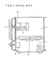
- FIG.1 shows one of such conventional microwave heating oven.
- the control box 2 containing electric parts is disposed below the heating chamber 1.
- the front door 3 is disposed at the front opening la of such heating chamber 1.
- the front door 3 has a hook 3a for locking the front door 3.
- the safety switch 7 is disposed at the position involving such hook 3a on the side wall of the heating chamber.
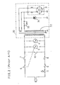
- FIG.2 shows a control circuit of such a conventional microwave heating oven.
- the control circuit comprises, a magnetron 31, a high voltage transformer 32, a high voltage capacitor 33, a diode 34, a cooling fan motor 4, a timer control motor 5, and so on.
- the safety standard for example UL standard, at least two safety switches 7 and 8 must be disposed in such electric circuit for making microwave, which are responding to the open-close action of the front door 3. Further, a short switch 10 also must be disposed on such electric circuit, so as to act on in case of deposition of such safety switches 7 and 8, to melt down the fuse 9.
- the conventional microwave heating oven has a thermal switch 11 which is, for example, a fuse switch or a bimetal switch, so as to break off the electric circuit for making microwave 30 and the cooling fan motor 4 in case of abnormal high temperature or fire trouble of food.
- the position of the thermal switch is determined after designing of a passage of the exhaust gas from the cooked food by trial and error of the experiment.
- the safety switch responding to the open-close action of the front door must be disposed at the position to be showered by the microwave, which is shown in FIG.I. So that, such a heating oven has the following problems. First, shower of microwave destroys the safety switch, second at receiving such microwave shower, wires of control circuit radiate electric noise which a badly affect the television set or the radio.
- the pourpose of the present invention is to provide a microwave heating oven having safety swiches, especially that wherein at least one of such safety switches serves as a thermal switch.
- a microwave heating oven in accordance with the present invention comprises,
- the safety switches are safely shielded from the microwave and hence is not broken by the radiation of the microwave, and on the other hand the switch can be opened with quick response to the abnormal high temperature or a fire trouble.
- FIC.6 is a perspective view of a microwave heating oven in accordance with the present invention.
- FIG.7 is a circuit diagram of an electric circuit of the microwave heating oven in accordance with the present invention.
- FIG.8 is a perspective view of a lock mechanism and switches for responding to a front door in accordance with FIG.6.
- FIG.3, FIG.4, FIG.5, FIG.6, FIG.7 and FIG.8 A preferred embodiment of a microwave heating oven in accordance with the present invention is shown in FIG.3, FIG.4, FIG.5, FIG.6, FIG.7 and FIG.8.
- a box made of a microwave-shielding substance, such as metal, and constituting a heating chamber 100 of such embodiment is designed to serve also as an external case, so as to make the size of the microwave heating oven compact and reduce cost.
- Panels 101, 102, 103, 104, 106, 107 and so on which are for example stainless steel, are made in box shape by known bending and calking and the like.
- a front door 110 is connected rotatably to the panel 107 by a known mechanism (which is not shown in the drawings). And a front part of the control box 200 is covered by a control panel 120.
- a timer 207 for controling the cooking time,(namely radiation time of microwave,) and a knob of the timer 208 are disposed at the front face of the control panel 120.
- the front door 110 has a projection part 110b and a fook part 110c on its inner face.
- the projection part 110b turns on a-safety switch 206 disposed on the control box 200 when the front door 110 is closed, and turns off the safety switch 206 when the front door 110 is opened.
- the hook part 110c is caught to be locked and released to be unlocked by a known mechanism in the control box 200, responding to the close action and open action of the door knob 110d of the front door 110 (the lock mechanism is not shown in the drawings), respectively.
- the control panel 120 has openings 120a and 120b, respectively for receiving the projection part 110b and the fook part 110c of the front door 110.
- the lock mechanism serves as another safety switch. These mechanism and the safety switches are shown in detail in FIG.8 and explained later.
- a rear cover 105 is fixed on the rear part of the heating chamber 100, and the space 300, which is enclosed by the panel 102 of the heating chamber 100 and the rear cover 105, constitutes the exhaust passage of the heating oven to exhaust the vapor or the like from the food 130 of heating object by the absorption of the cooling fan 204a.
- a safety switch 301 which turns off or on responding to the open-close action of the front door 110, is disposed.
- a switch rod 302 which transmits the open-close action of the front door 110 to the safety switch 301, is disposed through the upper part of the heating chamber 100.
- the switch rod 302 is always charged by a spring of safety switch 301 (which is not shown in figures) so as to be pushed out of the panel 107.
- a spring of safety switch 301 which is not shown in figures
- the switch rod 302 slides in the direction arrowed A by the force of the spring of the safety switch 301 and is pushed out of the panel 107, so that the right end 302b of the switch rod 302 is separated from the safety switch 301, and the safety switch 301 is turned off.
- the safety switch 301 is responding to the open-close action of the front door 110.
- a magnetron 201 which generates the microwave
- a stirrer blade 209 which radiates the microwave equally on the food 130, are disposed.
- the food 130 is partitioned from the magnetron 201 and the stirrer blade 209 by a partition 140 made of ceramics or the like insulating substance.
- the safety swich 301 which is mentioned above, also serves as a thermal switch.
- the thermal switch is for sensing the abnormal high temperature or heat in the heating chamber 100 caused by the fire trouble of the food or the like, and for cutting off the electric circuit of microwave generating circuit 250 and the cooling fan motor 204, so that the opening of the thermal switch 301 prevents propagation of heat to the outside of the heating oven in an early stage.
- the constitution and operation of the thermal switch is as follows.
- the switch rod 302 is made of low dielectric loss materials such as polypropylene, so that it does not fire in normal heating of the radiation of the microwave, but it easily changes its' shape by the abnormal high temperature caused by the fire trouble of the food or the like. Accordingly, in case of the fire trouble of the food which is shown in FIG.4, the center part of the switch rod 302 changes its shape, and does not withstand the force of the spring of the safety switch 301 (which is not shown in figures). So, the spring returns to the normalcy and the right end 302b is pushed in the direction designated by arrow mark A. Then, the safety switch 301 is turned off and cuts off the electric circuit of making microwave 250 and the cooling fan motor 204.
- low dielectric loss materials such as polypropylene
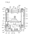
- FIG.5 is a cross-sectional plan view of the heating oven in accordance with FIG.3.
- the food 130 of heating object is disposed on the center of the heating chamber 100.
- the switch rod 302, the guide holder 305 and the safety switch 301 arc disposed on the right end part of the heating chamber 100.
- these switching mechanism is disposed on the upper part of the heating chamber 100, so the heating chamber 100 is hardly restricted by these switching mechanism.
- FIG.7 shows an example of electric circuit of the this embodiment of the microwave heating oven.
- the above-mentioned at least two safety switches 206 and 301 to complay with the safety standard are provided.
- the safety switches 206 and 301 are responding to the open-close action of the front door 110, are provided in such electric circuit.
- a short-circuiting switch 280 is also provided in such elecrtric circuit, to turn on in case of falure of the safety switches 206 and 301, so as to melt down a fuse 260.
- 270 designates a main switch.
- the short-circuiting switch 280 is provided to connect two power lines at the part beyond other safety switch 206, 301 and a fuse 260 in parallel with loads in this apparatus, and serves as lock mechanism of the front door 110.
- a timer motor 207a of a timer 207 which controls the heating time, the cooling fan motor 204 and an electric circuit for making microwave are connected in parallel.
- the microwave generating circuit 250 comprises the magnetron 201,the high voltage transformer 202, the high voltage capacitor 203, the diode 210 and so on.
- the present invention uses a thermal switch 301 as one of safety switches, and the safety switches are disposed at the position thermally isolated from the heating chamber, so that the safety switches of the present invention has high reliability.
- the electric circuit of the present invention has simplicity, and the microwave heating oven can be made without losing the compactness and the low cost, in comparison with the conventional compact type microwave heating oven.
Abstract
Description
- The present invention relates to a heating oven for example an electric oven or a microwave heating oven, especially a microwave heating oven having safety switches linked to respond to the open-close aclion of its front door which serves as a thermal switch.
- In the conventional microwave heating oven, a box which constitutes a heating chamber, is further enclosed in an external case. Because of such construction, it is difficult to make such a heating oven at a low cost, or to make such a heating oven easy in manufacture, or to make such a heating oven compact. In order to solve such problems, a heating oven in which the box of the heating chamber serving as the external case has been tried. For example, a heating oven wherein the control box containing electric parts is disposed at the side of the heating chamber, is shown in patent application Sho 59-105036, or a heating oven wherein the-control box.disposed below the heating chamber, is shown in patent application Sho 59-119319.
- FIG.1 shows one of such conventional microwave heating oven. In FIG.1, the
control box 2 containing electric parts is disposed below theheating chamber 1. The front door 3 is disposed at the front opening la ofsuch heating chamber 1. The front door 3 has a hook 3a for locking the front door 3. And thesafety switch 7 is disposed at the position involving such hook 3a on the side wall of the heating chamber. - FIG.2 shows a control circuit of such a conventional microwave heating oven. In FIG.2, the control circuit comprises, a
magnetron 31, ahigh voltage transformer 32, ahigh voltage capacitor 33, adiode 34, a cooling fan motor 4, a timer control motor 5, and so on. In the safety standard, for example UL standard, at least twosafety switches short switch 10 also must be disposed on such electric circuit, so as to act on in case of deposition ofsuch safety switches fuse 9. Furthermore, the conventional microwave heating oven has athermal switch 11 which is, for example, a fuse switch or a bimetal switch, so as to break off the electric circuit for makingmicrowave 30 and the cooling fan motor 4 in case of abnormal high temperature or fire trouble of food. In practical design of the microwave heating oven, the position of the thermal switch is determined after designing of a passage of the exhaust gas from the cooked food by trial and error of the experiment. - As improvement toward simplicity of the configuration of the heating oven proceeds, however, the safety switch responding to the open-close action of the front door must be disposed at the position to be showered by the microwave, which is shown in FIG.I. So that, such a heating oven has the following problems. First, shower of microwave destroys the safety switch, second at receiving such microwave shower, wires of control circuit radiate electric noise which a badly affect the television set or the radio.
- Further, in a microwave heating oven such as shown in patent application Sho 59-119319, the walls of the heating chamber serves as the external case, and so the heat is conveyed toward external part easily. Therefore, there is a strong demand for the quick responding thermal switch which can break down the electric circuit in a short time.
- The pourpose of the present invention is to provide a microwave heating oven having safety swiches, especially that wherein at least one of such safety switches serves as a thermal switch.
- A microwave heating oven in accordance with the present invention comprises,
- a heating chamber for containing and heating a heating object therein,
- a microwave generator for generating microwave for heating the heating object,
- a front door for covering a front opening part of the heating chamber,
- a safety switch which is disposed behind a microwave-shield and is for switching off the operation of the microwave generator, responding to opening action of the front door,
- transmission means for transmitting the opening action of the front door to the safety switch, disposed across and through the heating chamber.
- As a result of the above-mentioned configuration, the safety switches are safely shielded from the microwave and hence is not broken by the radiation of the microwave, and on the other hand the switch can be opened with quick response to the abnormal high temperature or a fire trouble.
-
- FIG.1 is the cross-sectional side view of the conventional microwave heating oven.
- FIG.2 is the drawing of the electric circuit for making microwave in accordance with the conventional microwave heating oven.
- FIG.3 is a cross-sectional side view of a microwave heating oven in accordance with the present invention.
- FIG.4 is a cross-sectional side view of the microwave heating oven in accordance with FIG.3, showing a case of a fire trouble and action of a safety switch serving as a thermal switch..
- FIG.5 is a cross-sectional plan view of the microwave heating oven of FIG.3.
- FIC.6 is a perspective view of a microwave heating oven in accordance with the present invention.
- FIG.7 is a circuit diagram of an electric circuit of the microwave heating oven in accordance with the present invention.
- FIG.8 is a perspective view of a lock mechanism and switches for responding to a front door in accordance with FIG.6.
- A preferred embodiment of a microwave heating oven in accordance with the present invention is shown in FIG.3, FIG.4, FIG.5, FIG.6, FIG.7 and FIG.8.
- As shown in FIG.3, a box made of a microwave-shielding substance, such as metal, and constituting a
heating chamber 100 of such embodiment is designed to serve also as an external case, so as to make the size of the microwave heating oven compact and reduce cost.Panels control box 200 in which amagnetron 201, ahigh voltage transformer 202, ahigh voltage capacitor 203, acooling fan motor 204, and so on are contained, is disposed below theheating chamber 100. At a front opening window of theheating chamber 100, afront door 110 is connected rotatably to thepanel 107 by a known mechanism (which is not shown in the drawings). And a front part of thecontrol box 200 is covered by acontrol panel 120. Atimer 207 for controling the cooking time,(namely radiation time of microwave,) and a knob of thetimer 208 are disposed at the front face of thecontrol panel 120. - As shown in FIG.6 which is a perspective view of the heating oven in accordance with FIG.3, the
front door 110 has aprojection part 110b and afook part 110c on its inner face. Theprojection part 110b turns on a-safetyswitch 206 disposed on thecontrol box 200 when thefront door 110 is closed, and turns off thesafety switch 206 when thefront door 110 is opened. And thehook part 110c is caught to be locked and released to be unlocked by a known mechanism in thecontrol box 200, responding to the close action and open action of thedoor knob 110d of the front door 110 (the lock mechanism is not shown in the drawings), respectively. - The
control panel 120 hasopenings projection part 110b and thefook part 110c of thefront door 110. And the lock mechanism serves as another safety switch. These mechanism and the safety switches are shown in detail in FIG.8 and explained later. - A
rear cover 105 is fixed on the rear part of theheating chamber 100, and thespace 300, which is enclosed by thepanel 102 of theheating chamber 100 and therear cover 105, constitutes the exhaust passage of the heating oven to exhaust the vapor or the like from thefood 130 of heating object by the absorption of thecooling fan 204a. On the inner face of therear cover 105, asafety switch 301 which turns off or on responding to the open-close action of thefront door 110, is disposed. Aswitch rod 302, which transmits the open-close action of thefront door 110 to thesafety switch 301, is disposed through the upper part of theheating chamber 100. And also, it is supported at both end parts in a direction shown by arrow marks A and B in FIG.3 bybushings 304 and at inbetween parts byguide holders 305. Theguide holders 305 are held by thepanels heating chamber 100. Theswitch rod 302 is always charged by a spring of safety switch 301 (which is not shown in figures) so as to be pushed out of thepanel 107. When thefront door 110 is opened, theswitch rod 302 slides in the direction arrowed A by the force of the spring of thesafety switch 301 and is pushed out of thepanel 107, so that theright end 302b of theswitch rod 302 is separated from thesafety switch 301, and thesafety switch 301 is turned off. And when thefront door 110 is closed, theinner face 110a of thefront door 110 contacts with theleft end 302a of theswitch rod 302, and so, theswitch rod 302 is withdrawed in the direction arrowed B, and thesafety switch 301 is turned on. Accordingly, thesafety switch 301 is responding to the open-close action of thefront door 110. - On the bottom of the
heating chamber 100, amagnetron 201 which generates the microwave, and astirrer blade 209 which radiates the microwave equally on thefood 130, are disposed. Thefood 130 is partitioned from themagnetron 201 and thestirrer blade 209 by a partition 140 made of ceramics or the like insulating substance. - The safety swich 301 which is mentioned above, also serves as a thermal switch. The thermal switch is for sensing the abnormal high temperature or heat in the
heating chamber 100 caused by the fire trouble of the food or the like, and for cutting off the electric circuit ofmicrowave generating circuit 250 and the coolingfan motor 204, so that the opening of thethermal switch 301 prevents propagation of heat to the outside of the heating oven in an early stage. - The constitution and operation of the thermal switch is as follows.
- The
switch rod 302 is made of low dielectric loss materials such as polypropylene, so that it does not fire in normal heating of the radiation of the microwave, but it easily changes its' shape by the abnormal high temperature caused by the fire trouble of the food or the like. Accordingly, in case of the fire trouble of the food which is shown in FIG.4, the center part of theswitch rod 302 changes its shape, and does not withstand the force of the spring of the safety switch 301 (which is not shown in figures). So, the spring returns to the normalcy and theright end 302b is pushed in the direction designated by arrow mark A. Then, thesafety switch 301 is turned off and cuts off the electric circuit of makingmicrowave 250 and the coolingfan motor 204. - FIG.5 is a cross-sectional plan view of the heating oven in accordance with FIG.3.
- On the center of the
heating chamber 100, thefood 130 of heating object is disposed. Theswitch rod 302, theguide holder 305 and thesafety switch 301 arc disposed on the right end part of theheating chamber 100. And also these switching mechanism is disposed on the upper part of theheating chamber 100, so theheating chamber 100 is hardly restricted by these switching mechanism. When the microwave is radiated to thefood 130 in cooking, the vapor or the like are produced. Such vapor is drafted through the panched holes 102a of thepanel 102 in FIG.5 and exhausted out of the heating oven by the coolingfan 204a in FIG.3. The exhaust passage is shown by the arrow marks. - FIG.7 shows an example of electric circuit of the this embodiment of the microwave heating oven. In the electric circuit the above-mentioned at least two
safety switches front door 110, are provided in such electric circuit. Further, a short-circuiting switch 280 is also provided in such elecrtric circuit, to turn on in case of falure of the safety switches 206 and 301, so as to melt down afuse 260. Incidentally, 270 designates a main switch. As shown in FIG.8, the short-circuiting switch 280 is provided to connect two power lines at the part beyondother safety switch fuse 260 in paralel with loads in this apparatus, and serves as lock mechanism of thefront door 110. - In such electric circuit, a
timer motor 207a of atimer 207 which controls the heating time, the coolingfan motor 204 and an electric circuit for making microwave are connected in paralel. Further, themicrowave generating circuit 250 comprises themagnetron 201,thehigh voltage transformer 202, thehigh voltage capacitor 203, thediode 210 and so on. - As mentioned above, the present invention uses a
thermal switch 301 as one of safety switches, and the safety switches are disposed at the position thermally isolated from the heating chamber, so that the safety switches of the present invention has high reliability. The electric circuit of the present invention has simplicity, and the microwave heating oven can be made without losing the compactness and the low cost, in comparison with the conventional compact type microwave heating oven.
Claims (14)
said safety switch is connected to turn on or off a microwave generator.
said transmission means is disposed in an upper part of said heating chamber.
said transmission means is made of low dielectric loss substance.
said safety switch is connected to turn on or off said microwave generator.
said transmisstion means is disposed in an upper part of said heating chamber.
said transmission means is made of low dielectric loss substance.
said external part of said heating chamber also serves as an exhaust passage.
said plural number of safety switches are connected to turn on or off said microwave generator.
said transmission means is disposed in an upper part of said heating chamber.
said transmission means is made of low dielectric loss substance.
Applications Claiming Priority (4)
| Application Number | Priority Date | Filing Date | Title |
|---|---|---|---|
| JP269767/84 | 1984-12-20 | ||
| JP26976784A JPS61147492A (en) | 1984-12-20 | 1984-12-20 | High frequency heater |
| JP2867385A JPS61186731A (en) | 1985-02-15 | 1985-02-15 | High-frequency heating equipment |
| JP28673/85 | 1985-02-15 |
Publications (3)
| Publication Number | Publication Date |
|---|---|
| EP0186104A2 true EP0186104A2 (en) | 1986-07-02 |
| EP0186104A3 EP0186104A3 (en) | 1988-03-02 |
| EP0186104B1 EP0186104B1 (en) | 1991-07-10 |
Family
ID=26366810
Family Applications (1)
| Application Number | Title | Priority Date | Filing Date |
|---|---|---|---|
| EP85116119A Expired EP0186104B1 (en) | 1984-12-20 | 1985-12-17 | Microwave heating oven |
Country Status (5)
| Country | Link |
|---|---|
| US (1) | US4663508A (en) |
| EP (1) | EP0186104B1 (en) |
| AU (1) | AU571363B2 (en) |
| CA (1) | CA1246684A (en) |
| DE (1) | DE3583431D1 (en) |
Cited By (23)
| Publication number | Priority date | Publication date | Assignee | Title |
|---|---|---|---|---|
| DE3730579A1 (en) * | 1987-09-11 | 1989-03-23 | Miele & Cie | Microwave oven with a safety device |
| EP0917408A2 (en) * | 1997-11-15 | 1999-05-19 | Lg Electronics Inc. | Air circulation structure for microwave oven |
| EP2194757A1 (en) * | 2008-12-04 | 2010-06-09 | Samsung Electronics Co., Ltd. | Microwave oven |
| EP2265090A1 (en) * | 2009-05-02 | 2010-12-22 | Electrolux Home Products Corporation N.V. | A microwave oven with a feed box system |
| US9572662B2 (en) | 2011-06-21 | 2017-02-21 | Twelve, Inc. | Prosthetic heart valve devices and associated systems and methods |
| US9655722B2 (en) | 2011-10-19 | 2017-05-23 | Twelve, Inc. | Prosthetic heart valve devices, prosthetic mitral valves and associated systems and methods |
| US9763780B2 (en) | 2011-10-19 | 2017-09-19 | Twelve, Inc. | Devices, systems and methods for heart valve replacement |
| US9901443B2 (en) | 2011-10-19 | 2018-02-27 | Twelve, Inc. | Prosthetic heart valve devices, prosthetic mitral valves and associated systems and methods |
| US10052204B2 (en) | 2011-10-19 | 2018-08-21 | Twelve, Inc. | Prosthetic heart valve devices, prosthetic mitral valves and associated systems and methods |
| US10111747B2 (en) | 2013-05-20 | 2018-10-30 | Twelve, Inc. | Implantable heart valve devices, mitral valve repair devices and associated systems and methods |
| US10238490B2 (en) | 2015-08-21 | 2019-03-26 | Twelve, Inc. | Implant heart valve devices, mitral valve repair devices and associated systems and methods |
| US10258468B2 (en) | 2012-03-01 | 2019-04-16 | Twelve, Inc. | Hydraulic delivery systems for prosthetic heart valve devices and associated methods |
| US10265172B2 (en) | 2016-04-29 | 2019-04-23 | Medtronic Vascular, Inc. | Prosthetic heart valve devices with tethered anchors and associated systems and methods |
| US10433961B2 (en) | 2017-04-18 | 2019-10-08 | Twelve, Inc. | Delivery systems with tethers for prosthetic heart valve devices and associated methods |
| US10517725B2 (en) | 2010-12-23 | 2019-12-31 | Twelve, Inc. | System for mitral valve repair and replacement |
| US10575950B2 (en) | 2017-04-18 | 2020-03-03 | Twelve, Inc. | Hydraulic systems for delivering prosthetic heart valve devices and associated methods |
| US10646338B2 (en) | 2017-06-02 | 2020-05-12 | Twelve, Inc. | Delivery systems with telescoping capsules for deploying prosthetic heart valve devices and associated methods |
| US10702380B2 (en) | 2011-10-19 | 2020-07-07 | Twelve, Inc. | Devices, systems and methods for heart valve replacement |
| US10702378B2 (en) | 2017-04-18 | 2020-07-07 | Twelve, Inc. | Prosthetic heart valve device and associated systems and methods |
| US10709591B2 (en) | 2017-06-06 | 2020-07-14 | Twelve, Inc. | Crimping device and method for loading stents and prosthetic heart valves |
| US10729541B2 (en) | 2017-07-06 | 2020-08-04 | Twelve, Inc. | Prosthetic heart valve devices and associated systems and methods |
| US10786352B2 (en) | 2017-07-06 | 2020-09-29 | Twelve, Inc. | Prosthetic heart valve devices and associated systems and methods |
| US10792151B2 (en) | 2017-05-11 | 2020-10-06 | Twelve, Inc. | Delivery systems for delivering prosthetic heart valve devices and associated methods |
Families Citing this family (9)
| Publication number | Priority date | Publication date | Assignee | Title |
|---|---|---|---|---|
| JPH07111907B2 (en) * | 1987-01-26 | 1995-11-29 | 松下電器産業株式会社 | High frequency heating device |
| US5270509A (en) * | 1991-12-24 | 1993-12-14 | Electric Power Research Institute | Microwave clothes drying system and method with improved arc detection |
| US5483045A (en) * | 1994-06-09 | 1996-01-09 | Electric Power Research Institute | Microwave power system and method with exposure protection |
| US5955795A (en) * | 1996-10-28 | 1999-09-21 | Beer; David W. | Apparatus for enclosing appliances |
| US7912548B2 (en) * | 2006-07-21 | 2011-03-22 | Cardiac Pacemakers, Inc. | Resonant structures for implantable devices |
| JP2010181112A (en) * | 2009-02-06 | 2010-08-19 | Sharp Corp | Drawer type heating cooker |
| US20170074766A1 (en) * | 2015-09-11 | 2017-03-16 | Cem Corporation | Moisture and volatiles analyzer |
| US10258196B2 (en) | 2017-08-25 | 2019-04-16 | Chhavi Gupta | Heat emitting pan lid with protective inner shield |
| US9930990B1 (en) * | 2017-08-25 | 2018-04-03 | Chhavi Gupta | Heat emitting pan lid |
Citations (1)
| Publication number | Priority date | Publication date | Assignee | Title |
|---|---|---|---|---|
| DE2949773A1 (en) * | 1979-12-11 | 1981-06-19 | Bosch-Siemens Hausgeräte GmbH, 7000 Stuttgart | Oven door lock for use during pyrolysis - has motor disconnecting cam and warning lamp actuating lever worked by lock bar |
Family Cites Families (3)
| Publication number | Priority date | Publication date | Assignee | Title |
|---|---|---|---|---|
| US3715552A (en) * | 1970-03-04 | 1973-02-06 | Tokyo Shibaura Electric Co | High frequency heating apparatus |
| US3766437A (en) * | 1972-04-03 | 1973-10-16 | Amana Refrigeration Inc | Safety interlock system for microwave ovens |
| JPS5743135A (en) * | 1980-08-29 | 1982-03-11 | Matsushita Electric Ind Co Ltd | High frequency heating device |
-
1985
- 1985-12-17 DE DE8585116119T patent/DE3583431D1/en not_active Expired - Lifetime
- 1985-12-17 EP EP85116119A patent/EP0186104B1/en not_active Expired
- 1985-12-18 CA CA000498016A patent/CA1246684A/en not_active Expired
- 1985-12-18 AU AU51402/85A patent/AU571363B2/en not_active Ceased
- 1985-12-19 US US06/810,567 patent/US4663508A/en not_active Expired - Lifetime
Patent Citations (1)
| Publication number | Priority date | Publication date | Assignee | Title |
|---|---|---|---|---|
| DE2949773A1 (en) * | 1979-12-11 | 1981-06-19 | Bosch-Siemens Hausgeräte GmbH, 7000 Stuttgart | Oven door lock for use during pyrolysis - has motor disconnecting cam and warning lamp actuating lever worked by lock bar |
Cited By (49)
| Publication number | Priority date | Publication date | Assignee | Title |
|---|---|---|---|---|
| DE3730579A1 (en) * | 1987-09-11 | 1989-03-23 | Miele & Cie | Microwave oven with a safety device |
| EP0917408A2 (en) * | 1997-11-15 | 1999-05-19 | Lg Electronics Inc. | Air circulation structure for microwave oven |
| EP0917408A3 (en) * | 1997-11-15 | 1999-12-01 | Lg Electronics Inc. | Air circulation structure for microwave oven |
| US6150648A (en) * | 1997-11-15 | 2000-11-21 | Lg Electronics, Inc. | Air circulation structure for microwave oven |
| EP2194757A1 (en) * | 2008-12-04 | 2010-06-09 | Samsung Electronics Co., Ltd. | Microwave oven |
| EP2265090A1 (en) * | 2009-05-02 | 2010-12-22 | Electrolux Home Products Corporation N.V. | A microwave oven with a feed box system |
| US11571303B2 (en) | 2010-12-23 | 2023-02-07 | Twelve, Inc. | System for mitral valve repair and replacement |
| US10517725B2 (en) | 2010-12-23 | 2019-12-31 | Twelve, Inc. | System for mitral valve repair and replacement |
| US10034750B2 (en) | 2011-06-21 | 2018-07-31 | Twelve, Inc. | Prosthetic heart valve devices and associated systems and methods |
| US11712334B2 (en) | 2011-06-21 | 2023-08-01 | Twelve, Inc. | Prosthetic heart valve devices and associated systems and methods |
| US9572662B2 (en) | 2011-06-21 | 2017-02-21 | Twelve, Inc. | Prosthetic heart valve devices and associated systems and methods |
| US9585751B2 (en) | 2011-06-21 | 2017-03-07 | Twelve, Inc. | Prosthetic heart valve devices and associated systems and methods |
| US10751173B2 (en) | 2011-06-21 | 2020-08-25 | Twelve, Inc. | Prosthetic heart valve devices and associated systems and methods |
| US11523900B2 (en) | 2011-06-21 | 2022-12-13 | Twelve, Inc. | Prosthetic heart valve devices and associated systems and methods |
| US10052204B2 (en) | 2011-10-19 | 2018-08-21 | Twelve, Inc. | Prosthetic heart valve devices, prosthetic mitral valves and associated systems and methods |
| US11826249B2 (en) | 2011-10-19 | 2023-11-28 | Twelve, Inc. | Devices, systems and methods for heart valve replacement |
| US9655722B2 (en) | 2011-10-19 | 2017-05-23 | Twelve, Inc. | Prosthetic heart valve devices, prosthetic mitral valves and associated systems and methods |
| US10299917B2 (en) | 2011-10-19 | 2019-05-28 | Twelve, Inc. | Prosthetic heart valve devices, prosthetic mitral valves and associated systems and methods |
| US10299927B2 (en) | 2011-10-19 | 2019-05-28 | Twelve, Inc. | Prosthetic heart valve devices, prosthetic mitral valves and associated systems and methods |
| US10335278B2 (en) | 2011-10-19 | 2019-07-02 | Twelve, Inc. | Prosthetic heart valve devices, prosthetic mitral valves and associated systems and methods |
| US9763780B2 (en) | 2011-10-19 | 2017-09-19 | Twelve, Inc. | Devices, systems and methods for heart valve replacement |
| US10016271B2 (en) | 2011-10-19 | 2018-07-10 | Twelve, Inc. | Prosthetic heart valve devices, prosthetic mitral valves and associated systems and methods |
| US9901443B2 (en) | 2011-10-19 | 2018-02-27 | Twelve, Inc. | Prosthetic heart valve devices, prosthetic mitral valves and associated systems and methods |
| US10702380B2 (en) | 2011-10-19 | 2020-07-07 | Twelve, Inc. | Devices, systems and methods for heart valve replacement |
| US10945835B2 (en) | 2011-10-19 | 2021-03-16 | Twelve, Inc. | Prosthetic heart valve devices, prosthetic mitral valves and associated systems and methods |
| US10258468B2 (en) | 2012-03-01 | 2019-04-16 | Twelve, Inc. | Hydraulic delivery systems for prosthetic heart valve devices and associated methods |
| US11129714B2 (en) | 2012-03-01 | 2021-09-28 | Twelve, Inc. | Hydraulic delivery systems for prosthetic heart valve devices and associated methods |
| US11234821B2 (en) | 2013-05-20 | 2022-02-01 | Twelve, Inc. | Implantable heart valve devices, mitral valve repair devices and associated systems and methods |
| US10111747B2 (en) | 2013-05-20 | 2018-10-30 | Twelve, Inc. | Implantable heart valve devices, mitral valve repair devices and associated systems and methods |
| US10238490B2 (en) | 2015-08-21 | 2019-03-26 | Twelve, Inc. | Implant heart valve devices, mitral valve repair devices and associated systems and methods |
| US11576782B2 (en) | 2015-08-21 | 2023-02-14 | Twelve, Inc. | Implantable heart valve devices, mitral valve repair devices and associated systems and methods |
| US10820996B2 (en) | 2015-08-21 | 2020-11-03 | Twelve, Inc. | Implantable heart valve devices, mitral valve repair devices and associated systems and methods |
| US11033390B2 (en) | 2016-04-29 | 2021-06-15 | Medtronic Vascular, Inc. | Prosthetic heart valve devices with tethered anchors and associated systems and methods |
| US10265172B2 (en) | 2016-04-29 | 2019-04-23 | Medtronic Vascular, Inc. | Prosthetic heart valve devices with tethered anchors and associated systems and methods |
| US11654021B2 (en) | 2017-04-18 | 2023-05-23 | Twelve, Inc. | Prosthetic heart valve device and associated systems and methods |
| US11737873B2 (en) | 2017-04-18 | 2023-08-29 | Twelve, Inc. | Hydraulic systems for delivering prosthetic heart valve devices and associated methods |
| US10575950B2 (en) | 2017-04-18 | 2020-03-03 | Twelve, Inc. | Hydraulic systems for delivering prosthetic heart valve devices and associated methods |
| US11389295B2 (en) | 2017-04-18 | 2022-07-19 | Twelve, Inc. | Delivery systems with tethers for prosthetic heart valve devices and associated methods |
| US10433961B2 (en) | 2017-04-18 | 2019-10-08 | Twelve, Inc. | Delivery systems with tethers for prosthetic heart valve devices and associated methods |
| US10702378B2 (en) | 2017-04-18 | 2020-07-07 | Twelve, Inc. | Prosthetic heart valve device and associated systems and methods |
| US10792151B2 (en) | 2017-05-11 | 2020-10-06 | Twelve, Inc. | Delivery systems for delivering prosthetic heart valve devices and associated methods |
| US11786370B2 (en) | 2017-05-11 | 2023-10-17 | Twelve, Inc. | Delivery systems for delivering prosthetic heart valve devices and associated methods |
| US10646338B2 (en) | 2017-06-02 | 2020-05-12 | Twelve, Inc. | Delivery systems with telescoping capsules for deploying prosthetic heart valve devices and associated methods |
| US11559398B2 (en) | 2017-06-02 | 2023-01-24 | Twelve, Inc. | Delivery systems with telescoping capsules for deploying prosthetic heart valve devices and associated methods |
| US11464659B2 (en) | 2017-06-06 | 2022-10-11 | Twelve, Inc. | Crimping device for loading stents and prosthetic heart valves |
| US10709591B2 (en) | 2017-06-06 | 2020-07-14 | Twelve, Inc. | Crimping device and method for loading stents and prosthetic heart valves |
| US10786352B2 (en) | 2017-07-06 | 2020-09-29 | Twelve, Inc. | Prosthetic heart valve devices and associated systems and methods |
| US10729541B2 (en) | 2017-07-06 | 2020-08-04 | Twelve, Inc. | Prosthetic heart valve devices and associated systems and methods |
| US11877926B2 (en) | 2017-07-06 | 2024-01-23 | Twelve, Inc. | Prosthetic heart valve devices and associated systems and methods |
Also Published As
| Publication number | Publication date |
|---|---|
| EP0186104B1 (en) | 1991-07-10 |
| CA1246684A (en) | 1988-12-13 |
| AU5140285A (en) | 1986-06-26 |
| EP0186104A3 (en) | 1988-03-02 |
| AU571363B2 (en) | 1988-04-14 |
| US4663508A (en) | 1987-05-05 |
| DE3583431D1 (en) | 1991-08-14 |
Similar Documents
| Publication | Publication Date | Title |
|---|---|---|
| EP0186104A2 (en) | Microwave heating oven | |
| CA1191585A (en) | Door opening apparatus for heating appliance | |
| US3733456A (en) | Microwave oven door latch | |
| EP0828974A1 (en) | A control device for a domestic oven | |
| EP0058207A1 (en) | Heat cooking device | |
| EP0075309A2 (en) | Locking device for door of cooking apparatus | |
| EP0059765B1 (en) | Heating cooking device | |
| US4221949A (en) | Abnormal temperature detection and microwave generation suppression in a microwave oven | |
| EP0783240B1 (en) | Grill/convection microwave oven and convection cooking method thereof | |
| US5258595A (en) | Power source circuit for microwave oven | |
| US4278862A (en) | Combination microwave and gas oven | |
| GB2048028A (en) | Microwave heating apparatus | |
| EP0892586A2 (en) | Microwave furnace for high temperature melting, decomposition or reduction to ash | |
| KR100546902B1 (en) | A structure of latch-board for Microwave oven | |
| CA2154287C (en) | Microwave oven with a single thermostat to sense temperature of both the magnetron and the microwave cavity | |
| KR100283657B1 (en) | Safety circuit of wall-mounted microwave oven | |
| JP2509589B2 (en) | Cooking device | |
| JPS6317925Y2 (en) | ||
| KR980008919U (en) | microwave | |
| EP0121893A2 (en) | A door for a combination gas or electric and microwave oven | |
| JPS5924762B2 (en) | High frequency heating device | |
| KR940006288Y1 (en) | Safety device for a range | |
| JP2554204B2 (en) | microwave | |
| JPS593281Y2 (en) | High frequency heating device with steam generator | |
| US20030140797A1 (en) | Cooking apparatus |
Legal Events
| Date | Code | Title | Description |
|---|---|---|---|
| PUAI | Public reference made under article 153(3) epc to a published international application that has entered the european phase |
Free format text: ORIGINAL CODE: 0009012 |
|
| AK | Designated contracting states |
Kind code of ref document: A2 Designated state(s): DE FR GB SE |
|
| PUAL | Search report despatched |
Free format text: ORIGINAL CODE: 0009013 |
|
| RHK1 | Main classification (correction) |
Ipc: H05B 6/76 |
|
| AK | Designated contracting states |
Kind code of ref document: A3 Designated state(s): DE FR GB SE |
|
| 17P | Request for examination filed |
Effective date: 19880421 |
|
| 17Q | First examination report despatched |
Effective date: 19890831 |
|
| GRAA | (expected) grant |
Free format text: ORIGINAL CODE: 0009210 |
|
| AK | Designated contracting states |
Kind code of ref document: B1 Designated state(s): DE FR GB SE |
|
| ET | Fr: translation filed | ||
| REF | Corresponds to: |
Ref document number: 3583431 Country of ref document: DE Date of ref document: 19910814 |
|
| PLBE | No opposition filed within time limit |
Free format text: ORIGINAL CODE: 0009261 |
|
| STAA | Information on the status of an ep patent application or granted ep patent |
Free format text: STATUS: NO OPPOSITION FILED WITHIN TIME LIMIT |
|
| 26N | No opposition filed | ||
| PGFP | Annual fee paid to national office [announced via postgrant information from national office to epo] |
Ref country code: GB Payment date: 19941207 Year of fee payment: 10 |
|
| PGFP | Annual fee paid to national office [announced via postgrant information from national office to epo] |
Ref country code: DE Payment date: 19941208 Year of fee payment: 10 |
|
| PGFP | Annual fee paid to national office [announced via postgrant information from national office to epo] |
Ref country code: FR Payment date: 19941209 Year of fee payment: 10 |
|
| PGFP | Annual fee paid to national office [announced via postgrant information from national office to epo] |
Ref country code: SE Payment date: 19941215 Year of fee payment: 10 |
|
| EAL | Se: european patent in force in sweden |
Ref document number: 85116119.0 |
|
| PG25 | Lapsed in a contracting state [announced via postgrant information from national office to epo] |
Ref country code: GB Effective date: 19951217 |
|
| PG25 | Lapsed in a contracting state [announced via postgrant information from national office to epo] |
Ref country code: SE Effective date: 19951218 |
|
| GBPC | Gb: european patent ceased through non-payment of renewal fee |
Effective date: 19951217 |
|
| PG25 | Lapsed in a contracting state [announced via postgrant information from national office to epo] |
Ref country code: FR Effective date: 19960830 |
|
| PG25 | Lapsed in a contracting state [announced via postgrant information from national office to epo] |
Ref country code: DE Effective date: 19960903 |
|
| REG | Reference to a national code |
Ref country code: FR Ref legal event code: ST |