EP0185552A2 - Apparatus for controlling operating state of an internal combustion engine - Google Patents
Apparatus for controlling operating state of an internal combustion engine Download PDFInfo
- Publication number
- EP0185552A2 EP0185552A2 EP85309254A EP85309254A EP0185552A2 EP 0185552 A2 EP0185552 A2 EP 0185552A2 EP 85309254 A EP85309254 A EP 85309254A EP 85309254 A EP85309254 A EP 85309254A EP 0185552 A2 EP0185552 A2 EP 0185552A2
- Authority
- EP
- European Patent Office
- Prior art keywords
- combustion engine
- internal combustion
- intake air
- variables
- air quantity
- Prior art date
- Legal status (The legal status is an assumption and is not a legal conclusion. Google has not performed a legal analysis and makes no representation as to the accuracy of the status listed.)
- Granted
Links
Images


Classifications
-
- F—MECHANICAL ENGINEERING; LIGHTING; HEATING; WEAPONS; BLASTING
- F02—COMBUSTION ENGINES; HOT-GAS OR COMBUSTION-PRODUCT ENGINE PLANTS
- F02D—CONTROLLING COMBUSTION ENGINES
- F02D41/00—Electrical control of supply of combustible mixture or its constituents
- F02D41/02—Circuit arrangements for generating control signals
- F02D41/14—Introducing closed-loop corrections
- F02D41/1401—Introducing closed-loop corrections characterised by the control or regulation method
-
- F—MECHANICAL ENGINEERING; LIGHTING; HEATING; WEAPONS; BLASTING
- F02—COMBUSTION ENGINES; HOT-GAS OR COMBUSTION-PRODUCT ENGINE PLANTS
- F02D—CONTROLLING COMBUSTION ENGINES
- F02D43/00—Conjoint electrical control of two or more functions, e.g. ignition, fuel-air mixture, recirculation, supercharging or exhaust-gas treatment
-
- F—MECHANICAL ENGINEERING; LIGHTING; HEATING; WEAPONS; BLASTING
- F02—COMBUSTION ENGINES; HOT-GAS OR COMBUSTION-PRODUCT ENGINE PLANTS
- F02B—INTERNAL-COMBUSTION PISTON ENGINES; COMBUSTION ENGINES IN GENERAL
- F02B1/00—Engines characterised by fuel-air mixture compression
- F02B1/02—Engines characterised by fuel-air mixture compression with positive ignition
- F02B1/04—Engines characterised by fuel-air mixture compression with positive ignition with fuel-air mixture admission into cylinder
-
- F—MECHANICAL ENGINEERING; LIGHTING; HEATING; WEAPONS; BLASTING
- F02—COMBUSTION ENGINES; HOT-GAS OR COMBUSTION-PRODUCT ENGINE PLANTS
- F02D—CONTROLLING COMBUSTION ENGINES
- F02D41/00—Electrical control of supply of combustible mixture or its constituents
- F02D41/02—Circuit arrangements for generating control signals
- F02D41/14—Introducing closed-loop corrections
- F02D41/1401—Introducing closed-loop corrections characterised by the control or regulation method
- F02D2041/1413—Controller structures or design
- F02D2041/1415—Controller structures or design using a state feedback or a state space representation
- F02D2041/1416—Observer
-
- F—MECHANICAL ENGINEERING; LIGHTING; HEATING; WEAPONS; BLASTING
- F02—COMBUSTION ENGINES; HOT-GAS OR COMBUSTION-PRODUCT ENGINE PLANTS
- F02D—CONTROLLING COMBUSTION ENGINES
- F02D41/00—Electrical control of supply of combustible mixture or its constituents
- F02D41/02—Circuit arrangements for generating control signals
- F02D41/14—Introducing closed-loop corrections
- F02D41/1401—Introducing closed-loop corrections characterised by the control or regulation method
- F02D2041/1413—Controller structures or design
- F02D2041/1426—Controller structures or design taking into account control stability
-
- F—MECHANICAL ENGINEERING; LIGHTING; HEATING; WEAPONS; BLASTING
- F02—COMBUSTION ENGINES; HOT-GAS OR COMBUSTION-PRODUCT ENGINE PLANTS
- F02D—CONTROLLING COMBUSTION ENGINES
- F02D41/00—Electrical control of supply of combustible mixture or its constituents
- F02D41/02—Circuit arrangements for generating control signals
- F02D41/14—Introducing closed-loop corrections
- F02D41/1401—Introducing closed-loop corrections characterised by the control or regulation method
- F02D2041/1433—Introducing closed-loop corrections characterised by the control or regulation method using a model or simulation of the system
Definitions
- the operating state detecting means M4 may be used, depending on the type of the internal combustion engine M1, an O 2 sensor which detects the concentration of oxygen within exhaust gasses, a knock sensor which detects knocking of internal combustion engine M1, a coolant temperature sensor which detects the temperature of coolant of the internal combustion engine M1, and an intake air temperature sensor.
- the target value setting means M5 sets a target value of the operating state including at least output torque and intake air quantity of the internal combustion engine M1 on the basis of the amount of demand to the internal combustion engine M1, and is arranged to compute a target output torque and intake air quantity corresponding to the manipulated stroke of the accelerator and the state of the transmission. Especially, it operates in the present invention to compute the target intake air quantity as an intake air quantity which makes the amount of fuel supplied to the internal combustion engine M1 minimum.
- the target intake air quantity which provides minimum amount of fuel supplied to the internal combustion engine M1 can be obtained as follows.
- Fig. 5 is a torque diagram showing the relationship between intake air quantity AR and fuel supply amount FR when output torque T of the internal combustion engine M1 is made constant Assuming that the internal combustion engine is operated when an intake air quantity is Ab, fuel supply amount is at point "b" of Fb, and output torque equals To, it will be understood that the fuel supply amount Fa becomes minimum at a point (Aa, Fa) where the intake air quantity has been incremented by ⁇ Ao from that at point "b".
- the target value setting means M5 is constructed so that the fuel supply amount FR is made minimum with respsect to the target value AR of the intake air quantity, and may be realized generally by a control performed by a microcomputer or the like as a part of a control means M6 which will be described hereinlater.
- state variable X (k) is an amount indicating the internal state of the internal combustion engine M1
- this is not required to be a variable corresponding to actual physical amount, and therefore, this may be designed as a vector of an appropriate order which is suitable for indicating the sate of the internal combustion engine M1.
- Fig. 6 is a schematic structural diagram showing an internal combustion engine according to an embodiment of the present invention, and its peripheral units;
- Fig. 7 is a control system diagram showing a control model of a system where operating state of the internal combustion engine is controlled;
- Fig. 8 is a block diagram for the description of system identification;
- Fig. 9 is a flowchart showing one example of a control executed by an electronic control circuit;
- Fig. 10 is a flowchart showing one example of a control for obtaining intake air quantity with which fuel compution is made minimum; and the description will be given in this order.
- the input port 49 of the electronic control circuit 40 receives signals indicative of the amount of demand of the internal combustion engine 1 and its operating state from respective sensors. More specifically, it comprises an unshown analog input unit for receiving accelerator opening degree Acc from the accelerator opening degree sensor 37 as the amount of demand, intake air quantity AR from the airflow meter 3 as the opening state, intake air temperature Tha from the intake air temperature sensor 6, output torque T from the pressure sensor 27, coolant temperature Thw from the coolant temperature sensor 29 to A/C convert them and then to supply the same to the MPU 44 as data, and an unshown pulse input unit for receiving rotational speed N of the internal combustion engine 1 from the rotational speed sensor 31 and cylinder-determination signal from the cylinder-determination sensor 33.
- an unshown analog input unit for receiving accelerator opening degree Acc from the accelerator opening degree sensor 37 as the amount of demand, intake air quantity AR from the airflow meter 3 as the opening state, intake air temperature Tha from the intake air temperature sensor 6, output torque T from the pressure sensor 27, coolant temperature Thw from the coolant temperature sensor 29 to A
- the reference P5 indicates a perturbation component extracting portion which extracts a perturbation component from various values (Ta, ARa, Na) under the state where steady operating state in connection with output torque T, intake air quantity AR and rotational speed N.
- the condition of operation of the internal combustion engine 1, i.e. throttle opening degree ⁇ , a controlled variable relating to the fuel injection amount FR, which are obtained by the above-mentioned integrators P3, P4, the observer P6 and the feedback amount determining unit P7, are also handled as perturbation components ⁇ and ⁇ FR.
- the above-mentioned model having two inputs and three outputs is used for constructing the dynamic model of the internal combustion engine 1, and in addition to these coolant temperature Thw and intake air temperature
- the of the internal combustion engine 1 are also used as factors which change the dynamic behaviour of the system.
- the coolant temperature Thw and so on do not change the structure of the control system but changes the state of dynamic behaviour thereof. Therefore, when the dynamic model is constructed in connection with the control system of the internal combustion engine 1, the vectors A , B , Cof the state equation (1) and the output equation (2) are determined in accordance with the coolant temperature Thw and so on of the internal combustion engine 1.
- FIG. 8 is a diagram showing a system of the internal combustion engine 1 under steady state operation as a system having two inputs and three outputs by way of transfer functions G1(z) through G6(z).
- the reference z indicates z transformation of sampled values of the input/output signals, and it is assumed that G1(z) through G6(z) have appropriate order. Therefore, entire transfer function matrix G (z) is given by:
- the dynamic model of the present embodiment is obtained through system identification, and this dynamic model can be determined in the form that linear approximation is satisfied around a state where the internal combustion engine 1 operated under a given state. Therefore, the transfer function G1 (z) through G6(z) are respectively obtained through the above method in connection with a plurality of steady operating states, and respective state equations (1) and output equations (2), i.e. vectors A , B , C , are obtained where the relationship between input and output thereof is satisfied between perturbation components T.
- the MPU 44 executes repeatedly step 100 and following steps.
- the fuel injection valves 11 are opened and the throttle valve 7 is controlled via the actuator 35 using the fuel injection amount FR(k-1) and throttle valve opening degree ⁇ (k-1) both obtained in previous series of processings.
- the depressed stroke of the accelerator 38 is read by the accelerator sensor 37, and in a step 120 the operating state of the internal combustion engine 1, i.e. the output torque T(k-1), intake air quantity AR(k-1), and rotational speed N(k-1) and so on, is read from respective sensors.
- a nearest state (which will be referred to as operating points Ta, ARa, NA) among steady-state operating states taken as satisfying linear approximation when the dynamic model of the internal combustion engine 1 is constructed, is obtained from the operating state read in step 120.
- the operating state of the internal combustion engine 1 is obtained as perturbation components ( ⁇ T, ⁇ AR, ⁇ N) relative to the steady state points (Ta, ARa, Na). This processing corresponds to the perturbation component extracting portion P5 of Fig. 7.
- a target intake air quantity is determined as a value which makes fuel supply amount minimum on the basis of correlation between intake air quantity and fuel supply amount when output torque is made constant, and its control means is constructed as an integral-added optimal regulator which determines the amount of feedback on the basis of an optimal feedback gain predetermined according to the dynamic model of the system relating to the operation of the internal combustion engine.
Abstract
Description
- This invention relates to operating state control apparatus for an internal combustion engine, and more particularly, to apparatus for controlling operating state of an internal combustion engine with which operating state including at least output torque and intake air quantity of an internal combustion engine are satisfactorily controlled on the basis of a dynamic model of the system relating to the operation of the intemal combustion engine.
- While it is required for an internal combustion engine, as a prime mover, to realize desired output with stability in response to the manipulation of a driver, there is a tendency that the control of an intemal combustion engine is electronically performed so as to improve fuel cosumption and realize stable engine output
- Taking airlfuel ratio control of an internal combustion engine in which fuel injection amount is controlled as one example of such controls, the control is performed, as in fuel injection amount control apparatus whose structure is schematically shown in Fig. 2, according to classic feedback control theory. Namely, while the intake air quantity Q of an internal combustion engine E/G is determined by the opening degree of a throttle valve TH which opens and closes in response to accelerator, a basic fuel injection amount Tp is obtained as Tp = KxQ/N (wherein K is a constant) on the basis of load of the internal combustion engine E/G which load is determined as Q/N from the above-mentioned intake air quantity Q and rotational speed N. Then, this basic fuel amount Tp is feedback controlled by a feedback correction factor F (A/F) and so on which is determined by a detection signal from means for detecting air/fuel ratio of the intake air, such as an oxygen concentration sensor O2 provided to an exhaust system of the internal combustion engine E/G, and then fuel injection amount T realizing target airlfuel ratio is obtained.
- However, the apparatus for controlling operating state of an internal combustion engine using such prior art have sufferd from the following problems.
- (1) In normal internal combustion engines, the quantity of intake air is controlled by the opening degree of the throttle valve linked with the accelerator, and fuel amount suitable for intake air quantity is mixed with the intake air by way of a carburettor or a fuel injection valve. Therefore, the output torque and fuel consumption amount are simply determined by only the operated stroke of the accelerator, and thus it has been impossible to precisely control fuel amount to a neccessary output torque. In order to reduce fuel consumption amount, therefore, a way of control has been adopted so as to provide lean air/fuel ratio in accordance with operating state of the internal combustion engine.
- However, when the aid/fuel ratio is made large so that lean air/fuel ratio mixture is combusted to improve fuel consumtion of an internal combustion engine, there arises a problem that the output torque of the internal combustion engine drastically varies due to the variation of fuel supply amount caused from air/fuel ratio control. Fig. 3 is a graph showing the relationship between air/fuel ratio A/F and output torque T of an internal combustion engine, and when comparing a large air/fuel ratio region with a small air/fuel ratio region, the variation ATr, AT of the output torque T with respect to the variation in air/fuel ratio A/F are such that, as shown, the variation AT is in the large air/fuel ratio region is larger than the other. This means that engine operation under a large air/fuel ratio, i.e. with a lean mixture, results in unstable output torque. Namely, to stablize the output torque during the operation in lean air/fuel ratio range has essentially been difficult with conventional feedback control in which fuel supply amount is controlled in accordance with detected concentration of oxygen in the exhaust system.
- (2) As long as the control is peformed such that fuel supply amount is determined on the basis of detected intake air quantity of an internal combustion engine, there necessarily occurs a time lag in the fuel supply amount control, and therefore, when intake air quantity is increased by steping onto the accelerator for acceleration, there arises a problem that output torque of the internal combustion engine rises once and then the air/fuel ratio becomes lean generating lean spike. This problem appears during deceleration in the form that a rich spike appears in air/fuel ratio, and in either cases there arises a problem that satisfactory acceleration/deceleration characteristic cannot be obtained because reverse swing phenomenon occurs in the output torque characteristic required to the internal combustion engine.
- Examples of such lean spike and rich spike are shown in Fig. 4.
- (3) To solve the problem of the above-mentioned (2), an internal combustion engine control apparatus can be thought (for example, "Accelerator Control Apparatus for Vehicles" disclosed in Patent Provisional Publication 59-122743) in which fuel supply amount is incxeaseed first when the accelerator is dePressed, and then the intake air quantity is increased by opening the throttle valve with an arrangement that the throttle valve, which has convetionally been linked with the accelerator, is driven by way of an actuator. However, the control of the opening degree of the throttle valve encounters the following problems in connection with response and stability. Namely, in the conventional feedback control, in which controlled variables of an actuator is determined in accordance with the deviation of an actual opening degree from a target opening degree, if feedback gain is increased to increase the amount of feedback so as to provide good driving feeling to the vehicle driver with the response of the control system being enhan- sed, excessive control would be resulted thereby overshooting and/or downshooting occurs. On the other hand, if the amount of feedback is reduced to realize stable control of intake air quantity, the follow-up characteristic is deteriorated while the driving feeling would be unsatisfactory. In this way, there is a contradiction in the conventional feedback control.
- For this reason, therefore, the simple structure for controlling the throttle valve opening degree by way of an actuator or the like does not provide perfect solution.
- (4) On the other hand, as one method of controlling an internal combustion engine, an idea of controlling the internal combustion engine precisely using dynamic models of the internal combustion engine formed through so called modem control theory was proposed. This idea contemplates to provide stable control of output torque and air/fuel ratio with satisfactory response using parameters which are determined by dynamic models of the internal combustion engine using target output torque and target airlfuel ratio which are set from amount of damands to the internal combustion engine. However, response suitable for given target value is just realized on the basis of dynamic models, and therefore, no control of minimizing fuel consumption is effected.
- The present invention has been made so as to solve the problems in the above-mentioned (1) through (4), and contemplates to provide apparatus for controlling operating state of an internal combustion engine with which apparatus engine output torque shows desired response and stability while fuel consumption amount can be made minimum.
- The present invention has been developed in order to remove the above-described drawbacks inherent to the conventional apparatus for controlling operating state of an internal combustion engine.
- It is, therefore, an object of the present invention to provide a new and useful apparatus for controlling operating state of an internal combustion engine with which quick response and high stability in operation are obtained, while output torque of the engine is controlled to a desired target value consuming minimum amount of fuel.
- According to a feature of the present invention the occurrence of lean spike and rich spike is effectively suppressed so as to provide confortable drive feeling to a vehicle driver of a motor vehicle whose engine is controlled according to the present invention.
- In accordance with the present invention there is provided apparatus for controlling operating state of an internal combustion engine comprising: demand amount detecting means M2 for detecting demand amount including at least the manipulation amount of an accelerator as an amount of damand for the operation of said internal combustion engine Mt; operating condition varying unit or means M3 for varying variables of operating condition including at least fuel supply amount and throttle valve opening degree as conditions of operation of said internal combustion engine M1; operating state detecting unit or means M4 for detecting variables of operating state including at least intake air quantity, rotational speed and output torque as the operaring state of said internal
combustion engine M 1; target value setting unit or means M5 for determining respective target values of operating state variables including at least target output torque and target intake air quantity using said demand amount detected, control unit or means M6 for controlling said operating condition varying unit or means by determining feedback amount of said operating condition variables so that variables of the detected operating state of said internal combustion engine M1 are equal to said determined target values; characterized in that said target value setting unit or means M5 is constructed such that said target intake air quantity is determined as an intake air quantity with which said fuel supply amount becomes minimum on the basis of the correlation between intake air quantity and fuel supply amount when output torque is made constant; and in that said control unit or means M6 is constructed as an integral-added optimal regulator which determines said feedback amount on the basis of an optimal feedback gain predetermined in accordance with dynamic model of a system relating to the operation of said internal combustion engine M1. - The object and features of the present invention will become more readily apparent from the following detailed description of the preferred embodiments taken in conjunction with the accompanying drawings in which:
- Fig. 1 is a basic structual diagram of the present invention;
- Fig. 2 is a schematic diagram showing briefly a conven- tonal control apparatus for an internal combustion engine;
- Fig. 3 is a graph showing the relatioship between air/fuel ratio and output torque;
- Fig. 4 is a graph for the description of lean spike and rich spike;
- Fig. 5 is a constant-torque diagram showing the relationship between fuel amount FR and intake air quantity AR;
- Fig. 6 is a schematic structural diagram showing the structure of an internal combustion engine and its peripheral units as an embodiment of the present invention;
- Fig. 7 is a control system diagram of the embodiment;
- Fig. 8 is a block diagram used for identifying a model of a system of the embodiment;
- Fig. 9 is a signal flow diagram for obtaining transfer function;
- Fig. 10 is a flowchart showing the control as an integral-added optimal regulator in the embodiment;
- Fig. 11 is a flowchart showing a control routine with which fuel consumption amount is minimized; and
- Fig. 12 is a graph for the comparison of the control characteristic between the embodiment and one example of the conventional control.
- The same or corresponding elements and parts are designated at like reference numerals throughout the drawings.
- Referring now to Fig. 1, a schematic structural diagram of an embodiment of the present invention is shown. The reference M1 indicates an internal combustion engine to be controlled by the present invention, and the apparatus for controlling the operating state of the
engine 1 comprises a demand amount detecting means M2, an operating condition varying means M3, an operating state detecting means M4, a target value setting means M5, and a control means M6. - As the internal combustion engine M1 may be used any engine as long as a gasoline engine irrespective of the number of cyliders and the number of cycles.
- The damand amount detecting means M2 is one which detects amount of driver's demand to the output of the internal combustion engine M1, such as the stroke of the accelerator of the internal combustion engine mounted on a motor vehicle, and also indudes, other than accelerator, one which detects the demand of increase or decrease of the output of the internal combustion engine M1 in accordance with the variation in load of the internal combustion engine M1. For instance, an on-off signal from a compressor of a vehicle mounted air-conditioner, an idle up signal produced during idling and so on may correspond to this.
- The operating condition varying means M3 is a means such as a set of actuators which vary the condition of operation of the internal combustion engine M1 including at least fuel supply amount and throttle valve opening degree, and may be electromagnetic fuel injection valve which opens in response to a signal from the control means M5 and is capable of changing amount of fuel injected by changing the valve-opneing duration or an actuator or the like which changes the opening degree of the throttle valve by way of a motor or the like. As the operating condition varying means M3 may be additional used, depending on the type of the internal combustion engine M1, EGR amount control means includiing an electromagnetic valve or the like for changing the amount of recirculated exhaust gasses (EGR amount) or one which changes ignition timing of the internal combustion engine M1.
- The operating state detecting means M4 is a set of sensors which detect variables of the operating state of the internal combustion engine including at least its output torque, rotational speed, intake air quantity, and may be a torque sensor or sensor which detects output torque, such as a cylinder internal pressure sensor for detecting combustion pressure, a sensor for detecting intake air quantity such as an airflow meter or an intake pipe pressure sensor, a rotational speed sensor which outputs a pulse signal having a frequency proportional to the rotational speed of the internal combustion engine M1 using the rotation of a rotor of a distributor. In addition, as the operating state detecting means M4 may be used, depending on the type of the internal combustion engine M1, an O2 sensor which detects the concentration of oxygen within exhaust gasses, a knock sensor which detects knocking of internal combustion engine M1, a coolant temperature sensor which detects the temperature of coolant of the internal combustion engine M1, and an intake air temperature sensor.
- The target value setting means M5 sets a target value of the operating state including at least output torque and intake air quantity of the internal combustion engine M1 on the basis of the amount of demand to the internal combustion engine M1, and is arranged to compute a target output torque and intake air quantity corresponding to the manipulated stroke of the accelerator and the state of the transmission. Especially, it operates in the present invention to compute the target intake air quantity as an intake air quantity which makes the amount of fuel supplied to the internal combustion engine M1 minimum. Here, the target intake air quantity which provides minimum amount of fuel supplied to the internal combustion engine M1 can be obtained as follows.
- Fig. 5 is a torque diagram showing the relationship between intake air quantity AR and fuel supply amount FR when output torque T of the internal combustion engine M1 is made constant Assuming that the internal combustion engine is operated when an intake air quantity is Ab, fuel supply amount is at point "b" of Fb, and output torque equals To, it will be understood that the fuel supply amount Fa becomes minimum at a point (Aa, Fa) where the intake air quantity has been incremented by ΔAo from that at point "b". The target value setting means M5 is constructed so that the fuel supply amount FR is made minimum with respsect to the target value AR of the intake air quantity, and may be realized generally by a control performed by a microcomputer or the like as a part of a control means M6 which will be described hereinlater.
- The control means M6 is realized by an electronic circuit constructed using a microprocessor together with a ROM, a RAM, peripheral units and input/output circuits, and is arranged to control the operating condition varying means M2 using feedback amount determined by optimal feedback gain determined by dynamic models of the system relating to the operation of the internal combustion engine M1 so that the operating state approaches the target Namely, the control means M6 is constructed as an integral-added optimal regulator which determines optimal amount of feedback from the variables of the operating state of the internal combustion engine Ml and the target value set by the target value setting means M5.
- A method of constituting such integral-added optimal regulator is described in detail in documents, such as "Linear System Control Theory" written by Katsuhisa FURUTA published by Shokodo Japan in 1976. An outlook for the method of actual forming of such regulator will be given hereinbelow. In the following description, the referen- cesF, X, A, B, C ,y,u,L,G , G, R, T, P indicate vectors (matrix), a superscript such as A Tindicating transposed matrix, a superscript - such as A -1 indicating inverse matrix, a symbol such as indicating an estimate, a symbol - such as indicating an amount handled by another system, i.e. a state observer (which will be simply referred to as observer hereinafter) which amount is generated by way of transform or the like from the system which is a controlled object, a symbol such as y indicating a target value respectively.
- It is known in modem control theory that in a control of a controlled object, i.e. the control of the internal combustion engine M1 in this case, the dynamic behavior of the controlled object is described in discrete-time system as:


- The above Eq. (1) is called a state equation, and Eq. (2) is called an output equation, and a term X (k) indicates state variables which represent the internal state of the internal combustion engine M1, a term u (k) indicates vectors comprising variables indicative of condition of operation of the internal combustion engine M1, and a term y (k) indicates vectors comprising variables representing the operating state of the internal combustion engine M1. The Eqs. (1) and (2) are both described in discrete-time system, and a subscript "k" indicates that the value is of the present time, while a subscript "k-1" indicates that the value is of an instant which is one sampling cycle before the present time.
- The state variables X (k) indicating the internal state of the internal combustion engine M1 represents information relating to the history of the system which is necessary and sufficient for predicting the influence in future in the control system. Therefore, the dynamic model of the system relating to the operation of the internal combustion engine M1 will be clear, and if we can determine vectors A , B and C of Eqs. (1) and (2), then it is possible to optimally control the operation of the internal combustion engine using the state variables X (k). In a servo system, while the system has to be expanded, this will be described hereinlater.
- It is difficult to accurately theoretically obtain dynamic models of a complex objective such as an internal combustion engine M1, and therefore, it is necessay to obtain the same through experiments. This is a method of constructing a model, which method is so called system identification, and in the case that internal combustion engine M1 is operated under a given state, the model is constructed according to state equation (1) and output equation (2) with which linear approximation is satisfied around the given state. Therefore, even in the case that the dynamic model related to the operation of the internal combustion engine M1 is of nonlinear, linear approximation can be performed by dividing into a plurality of normal operating states, and therefore it is possible to determine each dynamic model.
- If the controlled object is of a sort that a physical model can be relatively easily constructed, then the model (i.e. vectors A , B , and C ) of a dynamic system can be determined through system identification which can be made through a method such as frequency response method or spectrum analysis. However, in the case of controlled object of multivariable system, such as the internal combustion engine M1, it is difficult to make a physical model which is accurately approximated, and in such a case, dynamic model is constructed through least square method, instrumental variable method or on-line identification.
- Once a dynamic model is determined, an amount of feedback is determined from the state variables X (x), the variables y(k) of the operating condition and its target temperature y (k), so that controlled variables u (k) of the condition of operation are theoretically and optimally determined. In an internal combustion engine M1 or the like, as variables directly influencing on the operation of the internal combustion engine M1, such as air amount actually sucked and the dynamic behaviour of combustion, or fuel amount within the mixture related to combustion, output torque of the internal combustion engine, may be treated as the state variables X (k). However, most of such variables are difficult to be directly measured. Therefore, means called state observer (observer) is formed within the control means M6 so that it is possible to estimate the state variables X (k) of the internal combustion engine M1 using values of the variables of the condition of operation of the internal combustion engine M and the variables of the operating state. This is the observer according to modem control theory, and various types of observer and their designing methods are known. These are described in detail, for instance, in "Mechanicaf System Control" written by Katsuhisa Furuta, published from Ohm Co. Ltd. in 1984, and the observer may be designed as a minimal order obsersver or a finite time settling observer in correspondence with the fashion of an applied controlled object, i.e. the internal combustion engine M1 and apparatus for controlling the operating state thereof.
- The control means M6 controls the condition of operation varying means M3, in a system expanded using measured state variables or state variables X (k) estimated by the above-mentioned observer and an accumulated value obtained by accumulating the differences between a target value of the operating state variables of the internal combustion engine M1 estimated by the target value setting means M5 and variables of actual operating state, by determining an optimal feedback amount from both thereof and also from a predetermined optimal feedback gain. The accumulated value is a value which is necessary since the target value of the operating state varies depending on the amount of demand to the internal combustion engine M1. In a control of a servo system, it is required generally to perform a control for cancelling steady-state error between the target value and an actual controlled variable, and this corresponds to the necessity of inclusion of 1/S(integration of th order) in a transfer function. In the case that a state equation is made with the transfer function of the sytem being determined through system identification as described in the above, it is preferable to include such integrated amount in view of stability against noise. In the present invention, I = 1, namely, integration of first order may be considered. Therefore, when the accumulated value is introduced into the above-mentioned state variable X (k) to expand the system so as to determine the feedback amount from these values and a predetermined optimal feedback gain F , the controlled variables of the controlled object, i.e. the variables of the condition of operation of the internal combustion engine M1, are determined as an integral-added optimal regulator.
- Nextty, it will be described in connection with optimal feedback gain. In an optimal regulator to which an integral element is added as described in the above, the way of finding a control input (the variables of the condition of operation of the internal combustion engine M1 in this case) which minimizes a performance index J is made dear, while it is also known that the optimal feedback gain can be obtained from a solution of Riccati equation, A , B , C matrixes of the state equation (1) and the output equation (2), and the weighted parameter used in performance index (see the above-mentioned book). In the above, the weighted parameter is initially arbitrarily given so as to change the weighting in the regulation, by the performance index J, of the behavior of the variables of the condition of operation of the internal combustion engine M1. It is possible to determine an optimal value through repetition of simulation by changing the weighted parameter by a given amount from the behavior of the blow off air variables which are obtained as the result of siumulation performed by a large computer with an arbitrary weighted parameter being given. As a result, an optimal feedback gain F is also determined.
- Therefore, the control means M4 in the operating state control apparatus for an internal combustion engine according to the present invention is formed as an integral-added optimal regulator using a dynamic model of the internal combustion engine M1 which dynamic model is determined in advance through system identification, and the parameter of the observer therein and an optimal feedback gain F and so on are determined in advance through simulation using the internal combustion engine M1.
- While it has been described that the state variable X (k) is an amount indicating the internal state of the internal combustion engine M1, this is not required to be a variable corresponding to actual physical amount, and therefore, this may be designed as a vector of an appropriate order which is suitable for indicating the sate of the internal combustion engine M1.
- The apparatus for controlling operating state of an internal combustion engine according to the present invenn- tion having the above-described structure operates such that target output torque and target intake air quantity are computed using the amount of demand to the internal combustion engine M1, such as variables including the manipulation amount of an accelerator by the target setting means M5, and then the control means M6 formed as an integral-added optimal regulator controls the operating condition varying means M3 with an optimal feedback amount being obtained with which variables of the internal combustion engine M1 equal the above-mentioned target values. Furthermore, since the target value setting means M5 operates to compute target intake air quantity so that the fuel consumption amount becomes minimum under a condition that the output torque of the internal combustion engine is constant, the apparatus for controlling the operating state of an internal combustion engine according to the present invention optimally controls the internal combustion engine M1 to obtain an oprating state where fuel consumption is minimum with a target output torque.
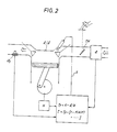
- Embodiments of the present invention will be described with reference to drawings in detail. Fig. 6 is a schematic structural diagram showing an internal combustion engine according to an embodiment of the present invention, and its peripheral units; Fig. 7 is a control system diagram showing a control model of a system where operating state of the internal combustion engine is controlled; Fig. 8 is a block diagram for the description of system identification; Fig. 9 is a flowchart showing one example of a control executed by an electronic control circuit; Fig. 10 is a flowchart showing one example of a control for obtaining intake air quantity with which fuel compution is made minimum; and the description will be given in this order.
- Although Fig. 6 shows a four-cylinder four cycle
internal combustion engine 1 in connection with only one cylinder, there are provided, in an order from upstream portion, an unshown air cleaner, an airflow meter for mesuring intake air quantity AR, an intakeair temperature sensor 5 for detecting an intake air temperature Tha, athrotde valve 7 for controlling intake air quantity, asurge tank 9, and electromagneticfule injection valves 11. Exhaust gasses from theinternal combustion engine 1 are exhausted outside from anexhaust pipe 14 via unshown exhaust gas cleaner, muffler and so on. While a comubstion chamber (cyfinder) is formed of apiston 15, anintake valve 17, anexhaust valve 19, aspark plug 21 and so on, description of the operation thereof is omitted since it is well known. Within thespark plug 21 arranged to form spark in receipt of a high voltage fed from an igniter 34 via adistributor 25, is built apressure sensor 27 of semiconductor type so as to detect combustion pressure, namely output of the internal combustion engine. This will be treated as output torque T hereinafter. - In addition to these, the
internal combustion engine 1 comprises acoolant temperture sensor 29 for detecting the temperature Thw of the coolant, a rotational speed sensor 32 installed in thedistributor 25 for outputting a pulse signal having a frequency corresponding to the rotational speed N of theinternal combustion engine 1, an a cylinder-determination sensor 33 for outputting a one-shot pulse per one revolution (720 ° crank angle) of theinternal combustion engine 1. The opening degree of thethrottle valve 7 is controlled by anactuator 35 whose prime mover is a d.c. motor. In Fig. 6, thereference 37 is an accelerator opening degree sensor for detecting the stroke Acc of theaccelerator 38. - In the internal combustion engine 1 and its peripheral devices having the above-mentioned structure the fuel injection amount FR, throttle valve opening degree θ and so on are controlled by an electronic control circuit 20. The electronic control circuit 40 is supplied with electrical power from a
battery 43 via a key switch 41, and comprises a well known microprocessor (MPU) 44,ROM 45,RAM 46,backup RAM 47,input port 49, output port 50, and so on, where the above-mentioned respective elements and ports are interconnected via abus 53. - The
input port 49 of the electronic control circuit 40 receives signals indicative of the amount of demand of theinternal combustion engine 1 and its operating state from respective sensors. More specifically, it comprises an unshown analog input unit for receiving accelerator opening degree Acc from the acceleratoropening degree sensor 37 as the amount of demand, intake air quantity AR from the airflow meter 3 as the opening state, intake air temperature Tha from the intake air temperature sensor 6, output torque T from thepressure sensor 27, coolant temperature Thw from thecoolant temperature sensor 29 to A/C convert them and then to supply the same to theMPU 44 as data, and an unshown pulse input unit for receiving rotational speed N of theinternal combustion engine 1 from therotational speed sensor 31 and cylinder-determination signal from the cylinder-determination sensor 33. - On the other hand, the
output port 51 outputs control signals for controlling opening degree 6 of thethrottle valve 7 via anactuator 35, fuel injection amount FR by opening and closing thefuel injection valves 11, and ignition timing via anigniter 24. The control by theMPU 44 of the electronic control circuit 40 will be described hereinlater in detail with reference to flowcharts of Figs. 10 and 11. - Now, the control system within the electronic control circuit 40 will be described with reference to a control diagram of Fig. 7, and especially, it will be described the way of vectors A , B , C of the state equation (1) and output equation (2) by way of system identification and the way of obtaining observer and feedback gain F based thereon taking actual examples. Fig. 7 is a diagram showing a control system, and does not show hardware structure. Furthermore, the control system shown in Fig. 7 is realized by executing a series of programs shown in the flowchart of Fig. 10 in practice, and is realized as a discrete-time system.
- As shown in Fig. 7, a target output torque T* is set by a torque setting unit P1 using accelerator opening degree Acc as base. On the other hand, a target intake air quantity AR* is determined as a value which causes minimum fuel consumption amount by a target intake air quantity setting unit P2 through a method which will be described in detail with reference to Fig. 11 hereiniater, using the target output torque T* , actually detected intake air quantity AR, output torque T, rotational speed N, and fuel injetion amount FR injected into the
internal combustion engine 1. Integrators P3 and P4 are used for obtaining an accumulated value ZT(k) by accumulating the deviations ST of target output torque T from actual output torque T, and another accumulated value ZAR(k) by accumulating deviations SAR of target intake air quantity AR from actual intake air quantity AR. - The reference P5 indicates a perturbation component extracting portion which extracts a perturbation component from various values (Ta, ARa, Na) under the state where steady operating state in connection with output torque T, intake air quantity AR and rotational speed N. This is based on the fact that the dynamic model of the system is constructed by regarding the operating state of the
internal combustion engine 1 as the continuance of regions where linear approximation is satisfied around a plurality of operating points in order to perform linear approximation for a nonlinear model. Therefore, variables of theinternal combustion engine 1 are handled as a perturbation component δT (= T - Ta), δAR (= AR - ARa), δN (= N - Na) relative to a predetermined nearest operating point The condition of operation of theinternal combustion engine 1, i.e. throttle opening degree θ, a controlled variable relating to the fuel injection amount FR, which are obtained by the above-mentioned integrators P3, P4, the observer P6 and the feedback amount determining unit P7, are also handled as perturbation components δθ and δFR. - The observer P6 obtains state estimated variables(k) by estimating state variables X (k) which represent the internal state of the
internal combustion engine 1 using the perturbation component δθ and δFR of the condition of operation and the perturbation components T, AR, and N of the above-mentioned operating state, and the state estimated variables X (k) and the above-mentioned accu- mutated value ZT(k) and AR(k) are multiplied by the optimal feedback gain F in the feedback amount determining portion P7 so as to obtain controlled variables (δθ, δFR). Since the set of the controlled variables (δθ, δFR) are perturbation components relative to operating condition corresponding to steady operating state selected by the perturbation component extracting portion P5, the variables θ and FR of the operating condition of theinternal combustion engine 1 are determined by adding reference setting values θa and FRa corresponding to the steady operating condition to the perturbation components by a reference setting value adding portion P8. - While the structure of the control system has briefly been described, the reason that these operating state (T, AR, N) and operating condition (9, FR) are used in this embodiment, is that these variables are basic values relating to the control of the
internal combustion engine 1. Therefore, in this embodiment, theinternal combustion engine 1 is grasped as a multivariable system of two inputs and three outputs. In addition to these, ignition timing and exhaust gas recirculation amount, for example, may be used as the amounts relating to the output of the internal combustionengine 1, and these may be taken into consideration when constructing a model of the control system. The above-mentioned model having two inputs and three outputs is used for constructing the dynamic model of theinternal combustion engine 1, and in addition to these coolant temperature Thw and intake air temperature The of theinternal combustion engine 1 are also used as factors which change the dynamic behaviour of the system. The coolant temperature Thw and so on do not change the structure of the control system but changes the state of dynamic behaviour thereof. Therefore, when the dynamic model is constructed in connection with the control system of theinternal combustion engine 1, the vectors A , B , Cof the state equation (1) and the output equation (2) are determined in accordance with the coolant temperature Thw and so on of theinternal combustion engine 1. - Hereinabove, the hardware structure of the
internal combustion engine 1 and the structure of the control system have been described taking a system of two inputs and three outputs as an example which controls the output of theinternal combustion engine 1. Now it will be described about the construction of a dynamic model through actual system identification, the designing of the observer P6, and how to give the optimal feedback gain F. - First of all, a dynamic model of the
internal combustion engine 1 is constructed. Fig. 8 is a diagram showing a system of theinternal combustion engine 1 under steady state operation as a system having two inputs and three outputs by way of transfer functions G1(z) through G6(z). The reference z indicates z transformation of sampled values of the input/output signals, and it is assumed that G1(z) through G6(z) have appropriate order. Therefore, entire transfer function matrix G (z) is given by: -

- When there exists an interference in the input/output variables, where the system is of two inputs and three outputs as in the
internal combustion engine 1 of this embodiment, it is extremely difficult to determine a physical model. In such a case, it is possible to obtain transfer function through simulation so called system identification. - The method of system identification is described in detail in "System Identification" written by Setsuo SAGARA published by Measurement and Automatic Control Society of Japan in 1981, and identification is performed here through least square method.
- The
internal combustion engine 1 is put in predetermined steady operating state, and the variation δθ of the throttle opening degree is made zero to add an appropriate test signal to the variation δFR of the supplied fuel amount and data of input δFR at this time and variation δN of the rotational speed as an output is sampled N times. This is expressed as input data series of {u(i)} = {δFRi} and as output data series of {y(i)} = {δNi} wherein i = 1, 2, 3 ... N. Here, the system can be regarded as having one input and one output, and thus the transfer function G1(z) is given by: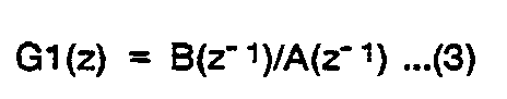

- In the above, Z-1 is a unit shift operator indicating Z-1·x(k) = x(k-1).
- When we determine parameters a1 to an and bO to bn of Eq. (4) from the input and output data series {u(i)} and {y(i)}, transfer function G1(z) can be obtained. These parameters are determined in system identification using least square method so that the following assumes a minimal value:

- In this embodiment, respective parameters have been obtained assuming that n = 2. In this case, a signal flow diagram of the system is as shown in Fig. 9, and using [X1(k)] as state variables, state and output equations thereof can be expresses by Eqs. (6) and (7):


- Therefore, using system parameters A 1', B 1', C 1' for the parameters A , B , C in the case that the system is regarded as of one input and one output, we obtain:

- In this embodiment, the following is obtained as the parameter in connection with G1 (z):
- [a1 a2] = [-1.91 0.923]
- [b0 b1 b2]
- = [0 4.86X10⁻³ 4.73×10⁻³]
- Through similar method transfer functions G2(z) through G6(z) as well as system parameters A 2' through A 6' , B 2' through B 6' , and C 2' through C 6' can be obtained. Therefore, using these system parameters, the system parameter of the original multivariable system of two inputs and three outputs, namely, vectors A , B , C of state equation (1) and output equation (2) can be determined.
- In this way, the dynamic model of the present embodiment is obtained through system identification, and this dynamic model can be determined in the form that linear approximation is satisfied around a state where the
internal combustion engine 1 operated under a given state. Therefore, the transfer function G1 (z) through G6(z) are respectively obtained through the above method in connection with a plurality of steady operating states, and respective state equations (1) and output equations (2), i.e. vectors A , B , C , are obtained where the relationship between input and output thereof is satisfied between perturbation components T. - Now the way of designing the observer P6 will be described. While as the way of designing is known Gopinath' method, which is described in detail in "Basic System Theory" written by katsuhisa FURUTA and Akira SANO published from Corona Co. Ltd. in 1978, the observer is designed as a minimal order observer in this embodiment
- The observer P6 is used for estimating the intemal state variable X (k) of the
internal combustion engine 1 from the perturbation component (δθ, δFR) of the variables of the condition of operation and from perturbation components (δT, δAR, δN) of the variables of the operating state of theinternal combustion engine 1, and the reason why the state estimated variables X (k) obtained by the observer P6 can be handled as actual state variable X (k) in the control of theinternal combustion engine 1 will be made dear hereinbelow. Let us assume that the output X(k) from the observer P6 is constructed as the following Eq. (9):
- In Eq. (9), L is a matrix arbrarily given. Modifying Eqs. (1), (2) and (9), we obtain:

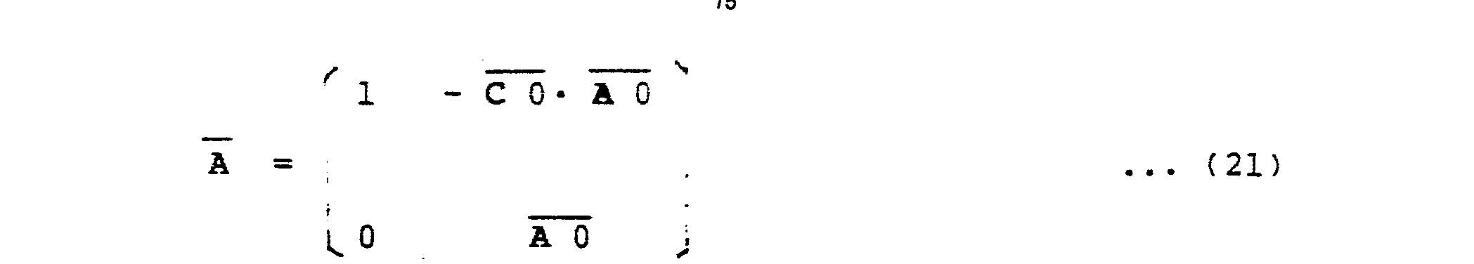
- Therefore, if the matrix L is selected so that an eigenvalue of the matrix ( A - L · C ) is located within a unit circle, X̂ (k) → X (k) with → ∞, and thus it is possible to accurately estimate the internal state variable X (k) of the controlled object using series u (*), y (**), from the past, of the input control vector u (k) and the output vector y (k).
- The vectors A , B , C of the state equation (1) and the output equation (2) both determined through system identification through least square methd, can be similarity transformed into the following observable canonical structure considering new state variables (k) = T- 1· X (k) using nonsinaular matrix T because the system is observable.


AO = T -1· A · T , BO = T -1 · B ,CO = C · T , and we obtain the following equations by selecting appropriate nonsigular T .


- Then, let L matrix be replaced as L = [-a1 -a2 ... -an]T, and we can now design a finite time settling observer as follows using equations (13), (14), and (15):

- In the above,
AO BO andCO are obtained through similarity transformation using A , B , and C , and it is also ensured that the control by the state equation is correct from this operation. - While the observer P6 has been designed using the vectors A , B and C of the state equation obtained through system identification, the output of the observer is now expressed in terms of (k) hereinafter.
- Now the way of obtaining the optimal feedback gain F will be described. Since the way of obtaining optimal feedback gain F is described in detail in the above-mentioned "Linear System Control Theory", only the results are shown here with the detail thereof being omitted.
- Using


internal combustion engine 1. - J= [ Y T (k)· Q· y (k) + u T(k)· R· u (k)] ...(19) In the above, Q and R indicate weighted parameter matrixes, and k indicates the number of sampling times which is zero at the time of beginning of control, while the right side of Eq. (19) is an expression of so called quadratic form using diagonal matrixes of Q and R .
- Here, the optimal feedback gain F is given as follows: F = -( R +
B T. p.B )-1·B T· P·A ...(20) - In Eq. (20), A and B are given by:

- Furthermore, P is a solution of the following Riccati equation:

- In the above, the performance index J in Eq. (19) has a meaning that it is intended to reduce the deviation of the operating state variables y(k), i.e. variables y(k) including at least the intake air quantity δAR, and rotational speed SN, from the target value y (k), with the variation of operating condition variables u (k) =[δθ δFR] as the control inputs to the
internal combustion engine 1 being regulated. The weighting of regulation of the variables u (k) of operating conditions can be altered by changing the values of the weighted parameter matrixes Qand R . Therefore, the state variables X (k) can be obtained as state estimated variables X (k) using Eq. (9) if we obtain the optimal feedback gain F using Eq. (20) by obtaining P solving Eq. (23) with arbitrarily weighted parameter matrixes Q, R being selectad using the dynamic model of theinternal combustion engine 1, i.e. matrixes A B, C (which correspond the the above- mentioedA ,B ,C ) which is obtained in advance. Therefore, the variables u (k) of the control input operating condition for theintemal combustion engine 1 can be obtained as follows: - u (k) = F ·[X1(k), X2(k) ... Xn(k) ZT(k) ZAR(k)]T ...(24)
- By repeating simulation with the weighted parameter matrixes Q and R being altered until an optimal control characteristic is obtained, the optimal feedback gain F is obtained.
- While it has been descxibed about the construction of the dynamic models of the control system of the
internal combustion engine 1 made through system identification using least square method, the designing of finite time settling observer and the computation of the optimal feedback gain F , these are obtained in advance so that actual control is performed within the electronic control unit 40 using only the results thereof. - Now, an actual control performed by the electronic control circuit 40 will be described with reference to a flowchart of Fig. 10. In the following description, an amount handled in a present processing is expressed by a subscript (k) and an amount handled in the latest cycle by another subscript (k-1).
- After the
internal combustion engine 1 starts operating, theMPU 44 executes repeatedly step 100 and following steps. At first in thestep 100, thefuel injection valves 11 are opened and thethrottle valve 7 is controlled via theactuator 35 using the fuel injection amount FR(k-1) and throttle valve opening degree θ(k-1) both obtained in previous series of processings. In a followingstep 110, the depressed stroke of theaccelerator 38 is read by theaccelerator sensor 37, and in astep 120 the operating state of theinternal combustion engine 1, i.e. the output torque T(k-1), intake air quantity AR(k-1), and rotational speed N(k-1) and so on, is read from respective sensors. - In a following
step 130, a target output torque T'of theinternal combustion engine 1 is computed on the basis of the depressed stroke of theaccelerator 38, and in a step 140 a target intake air quantity AR* of theinternal combustion engine 1 is computed. This target intate air quantity AR* is determined so that the amount of fuel consumed by theinternal combustion engine 1 is minimum, and the computation thereof is controlled as will be described hereinlater with reference to Fig. 11. These processings correspond to respective setting portions P1 and P2 of Fig. 7. - In a
step 150, the deviation ST of an actually detected output torque T(k-1) from the target output torque T* and the deviation SA of actual intake air quantity AR(k-1) from the target intake air quantity AR* are obtained. In asubsequent step 160, respective deviations obtained in thestep 150 are accumulated to obtain accumulated value ZT(k) using ZT(k) = ZT(k-1) + ST(k-1) and another accumulated value ZAR(k) using ZAR(k) = ZAR(k-1) + SA(k-1). This processing corresponds to the integrators P3 and P4 of Fig. 7. - In a following
step 170, a nearest state (which will be referred to as operating points Ta, ARa, NA) among steady-state operating states taken as satisfying linear approximation when the dynamic model of theinternal combustion engine 1 is constructed, is obtained from the operating state read instep 120. In astep 180, the operating state of theinternal combustion engine 1 is obtained as perturbation components (δT, δAR, δN) relative to the steady state points (Ta, ARa, Na). This processing corresponds to the perturbation component extracting portion P5 of Fig. 7. - In a subsequent step 190, temperature Thw of the coolant of the
internal combustion engine 1 is read, and sicne the dynamic model of theinternal combustion engine 1 changes in accordance with the coolant temperature Thw, parametersAO ,BO L and optimal feedback gain F prepared within the observer in advance for respective coolant temperatures Thw are selected. - In a
step 200, new state estimated value X (k) is obtained through the following equation (25) usingAO ,BO , L selected in the step 190, the perturbation components (δT, δAR, δN) obtained in thistep 180, state estimated value X (k-1) = [X1(k-1) X2(k-2) ... X6(k-1)]Tobtained in the previous cycle, the perturbation component δFR(k-1), δθ(k-1) of the fuel injection amount FR(k-1) and the throttle valve opening degree 8 (k-1) both obtained in the previous cycle. This processing corresponds to the observer P6 of Fig. 7, and the observer P6 is constructed as a finite time settling observer in this embodiment as described in the above. Namely, the following computation is performed:
- In a following
step 210, the state estimated value X(k) obtaiend in thestep 200, the accumulated values ZT(k), ZAR(k) obtained instep 160, the feedback gain prepared in advance and selected in the step 190 which feedback gain is given by:
- In a step 220, the perturbation components δFR(k), δθ(k) of the controlled variables obtained in the
step 210 are added to the respective controlled variables FRa, θa at the steady-state points, and controlled variables, i.e. operating conditions FR(k), s(k), actually outputted to thefuel injection valves 11 and theactuator 35 of theinternal combustion engine 1 are obtained. - In a following
step 230, the value "k" indicative of the number of times of samplings is incremented by 1, and the opertional flow returns to thestep 100 to repeat the above-mentioned series of processings, i.e. steps 100 through 230. - By continuously performing the above-mentioned control, the electronic control unit 40 performs control using an optimal feedback gain as an integral-added optimal regulator which controls the operating state of the
internal combustion engine 1 to the target output torque T*and to target intake air quantity AR*. - Now it will be described about a routine for obtaining the target intake air quantity AR* of the
step 140. In this routine, as shown in a flowchart of Fig. 11, the target intake air quantity AR*, which makes fuel consumption amount minimum while the same output torque T(k) is maintained, is computed through the following steps. In the following description, the target value of the previous cycle may be expressed in terms of AR* (k-1), and the target value newly computed in the present cycle may be expressed in terms of AR*(k). - This routine starts at a
step 300, and it is determined wheather the target output torque T*(k), the actual output torque T(k), and the rotational speed N(k) determined in the processing of Fig. 10 are respectively equal to previous cycle values T*(k-1, T(k-1) and N(k-1). In the case that one or more of the three values are not equal to the previous values, the control system has not reached equilibrium state, and therefore, it is determined that finding of intake air quantity, which makes fuel consumption amount minimum, cannot be performed, and the operational flow goes to astep 310. Then processing is performed so as to give intake air quantity AR(T, N), which is given from a preset map using output torque T and rotational speed N of theinternal combustion engine 1, as the target intake air quantity AR*(k). After this, the processing goes through NEXT to terminate this routine. Namely, turning back to the flowchart of Fig. 10 the target intake air quantity AR *(k) is determined assuming that the internal combustion engine is in transient state. - On the other hand, since the
internal combustion engine 1 is regarded as being in equilibrium state when the variables T*(k), T(k) and N(k) are all equal to previous values instep 300, then it is possible to search intake air quantity which makes fuel consumption amount minimum. Then the operational flow proceeds to astep 320. In thisstep 320, it is determined whether a flat Fs is "1" or not Since the value of the flag Fs is 0 before searching is started, the determination results in "NO" to proceeed to step 330. Instep 330, the flag Fs is set to "1", regarding that the searching for intake air quantity actualizing minimum fuel consumption amount is to be started, and a coefficient indicative of searching direction is set to "1" while a counter Cs indicative of the number of times of processings is set to "0". - In a subsequent-step 340, it is checked whether the value of the counter Cs has exceeded 0 or not Since counter Cs = 0 immediately after the start of searching, the oprational flow goes to a
step 350 to vary, i.e. increase, the target intake air quantity AR *(k) by DxΔAR from the previous target value AR* (k-1). In a followingstep 360, the value of the counter Cs is incremented by 1 to terminate the present routine through NEXT. - After such searching has started, when this routine is executed, the determinations in the
steps step 370 to check how the perturbation components δFR(k) in connection with the fuel injection amount FR(k) relative to the steady-state points are changed in comparison with the perturbation components FR(k-1) of previous cycle. - When the value of δFR(k) - δFR (k-1) is less than a predetermined vlaue -AF, it is regarded that the fuel injection amount is becoming smaller, and the
steps 350 et seq. are executed to continue searching. This indicates a situation in Fig. 5 where approaching from point "b" to point "a". - On the other hand, when the value of δFR(k) - δFR (k-1) is greater than the predetermined vlaue ΔF, it is regarded that the fuel injection amount is increasing, and the value of the searching direction flag D is set to "-1" in a
step 380 so as to revere the searching direction. Then the above-mentionedsteps - As the searching in a direction of reducing the fuel injection amount is being pertomed, then a point, at which the value of δFR(k) - δFR (k-1) is within a given deviation ± ΔF, will be found. This is the point corresponding to intake air quantity with which fuel consumption amount is minimum with constant output torque. Then, it is regarded that searching is finished, and the flag Fs is set to "0" in a
step 390, and in a followingstep 400 target intake air quantity AR*(k-1) obtained at this time is replaced with a value of a map which determines intake air quantity from output torque T and rotational speed N, namely, AT(T, R) = AR*(k-1). In asubsequent step 410, the value of AR (K-1) is renewed because the previously determined target intake air quantity AR*(k-1) is also used in the present cycle. Then this routine is terminated through NEXT. - One searching process is completed through the above, and then searching is continued from the processing at the beginning and steps 320, 330 and 340.
- As described in the above, by repeatedly executing the control routine of Figs. 10 and 11 the apparatus for controlling operating state of an internal combustion engine according to the present invention not only controls the operating state of the
internal combustion engine 1 to an output torque determined by the depressed stroke of theaccelerator 38 and to a rotational speed determined by load at this time, but also operates so as to minimize the fuel consumption amount At this time, the system controlling theinternal combustion engine 1 is an integral-added optimal regulator where the feedback gain gives optimal feedback, while the control of the throttle valve opening degree θ and the fuel injection amount FR are realized with quick response and stability which were impossible according to the conventional techniques. Accordingly, the driving feeling of the driver of theinternal combustion engine 1 is not deteriorated, and it is not possible to minimize the fuel consumption amount FR by changing the throttlevalve opening degree 9. - Furthermore, since the dynamic model varies in accordance with the temperature Thw of the coolant of the
internal combustion engine 1, the control is performed by switching the parameters of the observer and the optimal feedback gain depending on the coolant temperature Thw and thus it is possible to provide stable control irrespective of the variation of the temperature Thw of the coolant of theinternal combustion engine 1. - It is now possible to perform searching for minimizing the fuel injection amount FR of the
internal combustion engine 1 because such superior response and stability have been realized for the first time. This is because although searching is possible by driving the throttle valve by the actuator through conventional feedback control, such structure could not be practically used because of poor response and low stability. - Fig. 12 shows the above through comparison, and a dot-dash line "r" indicates the target value T*(k) of the output torque; a solid line "g" indicating an example of an output torque obtained when the control according to the present invention is effected, a dotted line "b" indicating an example of an output torque T(k) in the case of performing conventional feedback control. As is clear from the diaram, according to the apparatus for controlling operating state of an internal combustion engine according to the present invention which apparatus is formed as an integral-added optimal regulator, output torque can be controlled with a response (rising) which is quicker than that according to the conventional feedback control without suffering from substantial overshoot and undershoot Comparing time periods required until the output torque of the
internal combustion engine 1 reaches equilibrium state, it is understood that improvement by one or more degrees of magnitude has been attained, and this makes the searching practical with which searching the fuel injection amount is minimized. Therefore, the fuel consumption amount of theinternal combustion engine 1 is always controlled to be minimum when viewed macroscopically. - While high response characteristic has been realized, even when the airlfuel ratio of the
internal combustion engine 1 varies at lean side, there would not occur a problem of torque variation since the output torque is stably controlled. Similarly, the problem of lean spike and rich spike has also been resolved. When selecting an appropriate feedback gain F, it is possible to obtain, in the opposite way, rich spike on acceleration and lean spike on deceleration. - While in the above-mentioned embodiment, the
internal combustion engine 1 is grasped as a system of two inputs and three outputs because the fuel injection amount FR and the throttle valve opening degree 8 are used as the inputs and the output torque T, the intake air quantity AR, and the rotational speed N are used as the outputs, so as to form the integral-added optimal regulator by constructing dynamic model using system identification through least square method, it is also possible to construct dynamic model of a system considering other inputs and outputs without changing the pith of the present invention. - As described in detail hereinabove, the apparatus for controlling operating state of an internal combustion engine according to the present invention, a target intake air quantity is determined as a value which makes fuel supply amount minimum on the basis of correlation between intake air quantity and fuel supply amount when output torque is made constant, and its control means is constructed as an integral-added optimal regulator which determines the amount of feedback on the basis of an optimal feedback gain predetermined according to the dynamic model of the system relating to the operation of the internal combustion engine.
- Therefore, while high response and stability, which could not be obtained in the conventional internal combustion engine with a throttle actuator, are realized, the output torque of the internal combustion engine is controlled to a target value, and there is a superior advantage that the fuel consumption amount is minimized. Accordingly, when applying to an internal combustion engine of a motor vehicle, it is possible to remarkably improve the control characteristics of the operating state of the internal combustion engine such that the problem of lean spike and rich spike is resolved so as to provide comfortable drive feeling, while the fuel consumption by a motor vehicle is drastically reduced.
- The above-described embodiments are just examples of the present invention, and therefore, it will be apparent for those skilled in the art that many modifications and variations may be made without departing from the scope of the present invention.
Claims (8)
Applications Claiming Priority (2)
| Application Number | Priority Date | Filing Date | Title |
|---|---|---|---|
| JP59267765A JPH0697003B2 (en) | 1984-12-19 | 1984-12-19 | Internal combustion engine operating condition control device |
| JP267765/84 | 1984-12-19 |
Publications (3)
| Publication Number | Publication Date |
|---|---|
| EP0185552A2 true EP0185552A2 (en) | 1986-06-25 |
| EP0185552A3 EP0185552A3 (en) | 1987-09-23 |
| EP0185552B1 EP0185552B1 (en) | 1990-03-21 |
Family
ID=17449272
Family Applications (1)
| Application Number | Title | Priority Date | Filing Date |
|---|---|---|---|
| EP85309254A Expired EP0185552B1 (en) | 1984-12-19 | 1985-12-19 | Apparatus for controlling operating state of an internal combustion engine |
Country Status (4)
| Country | Link |
|---|---|
| US (1) | US4653449A (en) |
| EP (1) | EP0185552B1 (en) |
| JP (1) | JPH0697003B2 (en) |
| DE (1) | DE3576715D1 (en) |
Cited By (15)
| Publication number | Priority date | Publication date | Assignee | Title |
|---|---|---|---|---|
| EP0227536A1 (en) * | 1985-12-06 | 1987-07-01 | Cimsa Sintra | Feedback control apparatus for an internal-combustion engine, and method using such an apparatus |
| EP0286104A2 (en) * | 1987-04-08 | 1988-10-12 | Hitachi, Ltd. | Method of controlling fuel supply to engine by prediction calculation |
| EP0291953A1 (en) * | 1987-05-19 | 1988-11-23 | Nissan Motor Co., Ltd. | System for measuring amount of air introduced into combustion chamber of internal combustion engine with avoiding influence of temperature dependent air density variation and pulsatile air flow |
| EP0301548A2 (en) * | 1987-07-29 | 1989-02-01 | Toyota Jidosha Kabushiki Kaisha | Fuel injection system of an internal combustion engine |
| EP0312835A2 (en) * | 1987-10-22 | 1989-04-26 | Nippondenso Co., Ltd. | Control apparatus |
| EP0324489A2 (en) * | 1988-01-13 | 1989-07-19 | Hitachi, Ltd. | Method and apparatus for controlling internal combustion engines |
| EP0337366A2 (en) * | 1988-04-12 | 1989-10-18 | Toyota Jidosha Kabushiki Kaisha | A nonlinear feedback control method and apparatus for an internal combustion engine |
| US4974563A (en) * | 1988-05-23 | 1990-12-04 | Toyota Jidosha Kabushiki Kaisha | Apparatus for estimating intake air amount |
| GB2256727A (en) * | 1991-06-11 | 1992-12-16 | Nippon Denso Co | Air fuel ratio feedback control. |
| EP0534813A1 (en) * | 1991-09-27 | 1993-03-31 | Automobiles Peugeot | Method for correcting the control parameters of an internal combustion engine and device for implementing this method |
| GB2274926A (en) * | 1993-02-04 | 1994-08-10 | Fuji Heavy Ind Ltd | System for controlling a throttle valve in an automatic driving system for motor vehicles |
| EP0633395A2 (en) * | 1991-06-10 | 1995-01-11 | Nippondenso Co., Ltd. | Apparatus for controlling speed of internal combustion engine |
| GB2281133A (en) * | 1993-08-20 | 1995-02-22 | Nippon Denso Co | Control apparatus for an internal combustion engine |
| EP0886055A1 (en) * | 1997-06-19 | 1998-12-23 | Renault | Method and apparatus for controlling a spark ignited internal combustion engine |
| CN101363377B (en) * | 2007-08-06 | 2012-12-12 | Mtu腓特烈港有限责任公司 | Method for controlling an internal combustion engine |
Families Citing this family (69)
| Publication number | Priority date | Publication date | Assignee | Title |
|---|---|---|---|---|
| US4843556A (en) * | 1985-07-23 | 1989-06-27 | Lucas Industries Public Limited Company | Method and apparatus for controlling an internal combustion engine |
| JPH0660593B2 (en) * | 1985-08-05 | 1994-08-10 | 株式会社日立製作所 | Electronic internal combustion engine controller |
| JPS6287651A (en) * | 1985-10-12 | 1987-04-22 | Honda Motor Co Ltd | Method of controlling operating characteristic amount of operating control means in internal combustion engine |
| US4785780A (en) * | 1986-07-08 | 1988-11-22 | Nippondenso Co., Ltd. | Control apparatus |
| GB8700759D0 (en) * | 1987-01-14 | 1987-02-18 | Lucas Ind Plc | Adaptive control system |
| US5157613A (en) * | 1987-01-14 | 1992-10-20 | Lucas Industries Public Limited Company | Adaptive control system for an engine |
| JPS63253147A (en) * | 1987-04-09 | 1988-10-20 | Nissan Motor Co Ltd | Idling engine speed control device for internal combustion engine |
| JPH081146B2 (en) * | 1987-04-21 | 1996-01-10 | トヨタ自動車株式会社 | Nonlinear feedback control device for internal combustion engine |
| GB8715130D0 (en) * | 1987-06-27 | 1987-08-05 | Lucas Ind Plc | Adaptive control system for i c engine |
| GB8721688D0 (en) * | 1987-09-15 | 1987-10-21 | Lucas Ind Plc | Adaptive control system |
| JP2614636B2 (en) * | 1988-04-21 | 1997-05-28 | 株式会社日立製作所 | Control device for internal combustion engine |
| JP2748488B2 (en) * | 1989-01-18 | 1998-05-06 | 株式会社デンソー | Throttle opening control device |
| US5069181A (en) * | 1989-01-31 | 1991-12-03 | Mitsubishi Jidosha Kogyo Kabushiki Kaisha | Output control apparatus for an internal combustion engine |
| DE59009588D1 (en) * | 1990-03-17 | 1995-10-05 | Bosch Gmbh Robert | Error corrected control system. |
| IT1241215B (en) * | 1990-05-07 | 1993-12-29 | Fiat Auto Spa | PROCEDURE AND APPARATUS FOR THE CONTROL OF THE MINIMUM ROTATION SPEED OF AN INTERNAL COMBUSTION ENGINE. |
| JP2696431B2 (en) * | 1990-12-17 | 1998-01-14 | 株式会社ユニシアジェックス | Idle speed control device for internal combustion engine |
| JP3890847B2 (en) * | 2000-02-29 | 2007-03-07 | 株式会社日立製作所 | Automotive control device |
| JP3758134B2 (en) * | 2000-10-23 | 2006-03-22 | 株式会社デンソー | Control device for internal combustion engine |
| GB2388922B (en) * | 2002-01-31 | 2005-06-08 | Cambridge Consultants | Control system |
| US20070122698A1 (en) | 2004-04-02 | 2007-05-31 | Maxwell Technologies, Inc. | Dry-particle based adhesive and dry film and methods of making same |
| JP4297866B2 (en) * | 2004-11-09 | 2009-07-15 | 株式会社日立製作所 | Method for evaluating diagnostic function of variable valve mechanism and diagnostic device for variable valve mechanism |
| US7743606B2 (en) * | 2004-11-18 | 2010-06-29 | Honeywell International Inc. | Exhaust catalyst system |
| US7182075B2 (en) * | 2004-12-07 | 2007-02-27 | Honeywell International Inc. | EGR system |
| US7165399B2 (en) * | 2004-12-29 | 2007-01-23 | Honeywell International Inc. | Method and system for using a measure of fueling rate in the air side control of an engine |
| US7328577B2 (en) | 2004-12-29 | 2008-02-12 | Honeywell International Inc. | Multivariable control for an engine |
| US7275374B2 (en) * | 2004-12-29 | 2007-10-02 | Honeywell International Inc. | Coordinated multivariable control of fuel and air in engines |
| US7467614B2 (en) | 2004-12-29 | 2008-12-23 | Honeywell International Inc. | Pedal position and/or pedal change rate for use in control of an engine |
| US7591135B2 (en) * | 2004-12-29 | 2009-09-22 | Honeywell International Inc. | Method and system for using a measure of fueling rate in the air side control of an engine |
| US20060168945A1 (en) * | 2005-02-02 | 2006-08-03 | Honeywell International Inc. | Aftertreatment for combustion engines |
| US7752840B2 (en) * | 2005-03-24 | 2010-07-13 | Honeywell International Inc. | Engine exhaust heat exchanger |
| US7469177B2 (en) * | 2005-06-17 | 2008-12-23 | Honeywell International Inc. | Distributed control architecture for powertrains |
| US7389773B2 (en) | 2005-08-18 | 2008-06-24 | Honeywell International Inc. | Emissions sensors for fuel control in engines |
| US7155334B1 (en) | 2005-09-29 | 2006-12-26 | Honeywell International Inc. | Use of sensors in a state observer for a diesel engine |
| US7765792B2 (en) * | 2005-10-21 | 2010-08-03 | Honeywell International Inc. | System for particulate matter sensor signal processing |
| US7357125B2 (en) * | 2005-10-26 | 2008-04-15 | Honeywell International Inc. | Exhaust gas recirculation system |
| US20070144149A1 (en) * | 2005-12-28 | 2007-06-28 | Honeywell International Inc. | Controlled regeneration system |
| US7415389B2 (en) * | 2005-12-29 | 2008-08-19 | Honeywell International Inc. | Calibration of engine control systems |
| US7779812B2 (en) * | 2008-07-15 | 2010-08-24 | Ford Global Technologies, Llc | Vehicle stability and surge control |
| US8060290B2 (en) | 2008-07-17 | 2011-11-15 | Honeywell International Inc. | Configurable automotive controller |
| JP4924646B2 (en) * | 2009-03-31 | 2012-04-25 | 株式会社デンソー | Exhaust gas purification device for internal combustion engine |
| US8620461B2 (en) * | 2009-09-24 | 2013-12-31 | Honeywell International, Inc. | Method and system for updating tuning parameters of a controller |
| US8504175B2 (en) | 2010-06-02 | 2013-08-06 | Honeywell International Inc. | Using model predictive control to optimize variable trajectories and system control |
| US9677493B2 (en) | 2011-09-19 | 2017-06-13 | Honeywell Spol, S.R.O. | Coordinated engine and emissions control system |
| US20130111905A1 (en) | 2011-11-04 | 2013-05-09 | Honeywell Spol. S.R.O. | Integrated optimization and control of an engine and aftertreatment system |
| US9650934B2 (en) | 2011-11-04 | 2017-05-16 | Honeywell spol.s.r.o. | Engine and aftertreatment optimization system |
| WO2013080585A1 (en) * | 2011-11-28 | 2013-06-06 | 学校法人明治大学 | Detection device and detection method |
| US9714616B2 (en) | 2014-03-26 | 2017-07-25 | GM Global Technology Operations LLC | Non-model predictive control to model predictive control transitions |
| US9797318B2 (en) | 2013-08-02 | 2017-10-24 | GM Global Technology Operations LLC | Calibration systems and methods for model predictive controllers |
| US9920697B2 (en) | 2014-03-26 | 2018-03-20 | GM Global Technology Operations LLC | Engine control systems and methods for future torque request increases |
| US9863345B2 (en) | 2012-11-27 | 2018-01-09 | GM Global Technology Operations LLC | System and method for adjusting weighting values assigned to errors in target actuator values of an engine when controlling the engine using model predictive control |
| US9784198B2 (en) | 2015-02-12 | 2017-10-10 | GM Global Technology Operations LLC | Model predictive control systems and methods for increasing computational efficiency |
| US9732688B2 (en) | 2014-03-26 | 2017-08-15 | GM Global Technology Operations LLC | System and method for increasing the temperature of a catalyst when an engine is started using model predictive control |
| US9605615B2 (en) * | 2015-02-12 | 2017-03-28 | GM Global Technology Operations LLC | Model Predictive control systems and methods for increasing computational efficiency |
| DE102014224578A1 (en) * | 2014-12-02 | 2016-06-02 | Robert Bosch Gmbh | Method and device for operating a fuel metering system of an internal combustion engine |
| EP3051367B1 (en) | 2015-01-28 | 2020-11-25 | Honeywell spol s.r.o. | An approach and system for handling constraints for measured disturbances with uncertain preview |
| EP3056706A1 (en) | 2015-02-16 | 2016-08-17 | Honeywell International Inc. | An approach for aftertreatment system modeling and model identification |
| EP3091212A1 (en) | 2015-05-06 | 2016-11-09 | Honeywell International Inc. | An identification approach for internal combustion engine mean value models |
| JP6771272B2 (en) * | 2015-07-01 | 2020-10-21 | 日立オートモティブシステムズ株式会社 | In-vehicle electronic control device and stack usage |
| EP3734375B1 (en) | 2015-07-31 | 2023-04-05 | Garrett Transportation I Inc. | Quadratic program solver for mpc using variable ordering |
| US10272779B2 (en) | 2015-08-05 | 2019-04-30 | Garrett Transportation I Inc. | System and approach for dynamic vehicle speed optimization |
| US10415492B2 (en) | 2016-01-29 | 2019-09-17 | Garrett Transportation I Inc. | Engine system with inferential sensor |
| US10124750B2 (en) | 2016-04-26 | 2018-11-13 | Honeywell International Inc. | Vehicle security module system |
| US10036338B2 (en) | 2016-04-26 | 2018-07-31 | Honeywell International Inc. | Condition-based powertrain control system |
| US9938908B2 (en) | 2016-06-14 | 2018-04-10 | GM Global Technology Operations LLC | System and method for predicting a pedal position based on driver behavior and controlling one or more engine actuators based on the predicted pedal position |
| US11199120B2 (en) | 2016-11-29 | 2021-12-14 | Garrett Transportation I, Inc. | Inferential flow sensor |
| US10156197B1 (en) | 2017-06-16 | 2018-12-18 | GM Global Technology Operations LLC | Model predictive control systems and methods for increasing computational efficiency |
| US11057213B2 (en) | 2017-10-13 | 2021-07-06 | Garrett Transportation I, Inc. | Authentication system for electronic control unit on a bus |
| US11192561B2 (en) | 2019-05-21 | 2021-12-07 | GM Global Technology Operations LLC | Method for increasing control performance of model predictive control cost functions |
| CN117434911B (en) * | 2023-12-20 | 2024-04-16 | 北京东方国信科技股份有限公司 | Equipment running state monitoring method and device and electronic equipment |
Citations (7)
| Publication number | Priority date | Publication date | Assignee | Title |
|---|---|---|---|---|
| US4064846A (en) * | 1975-02-19 | 1977-12-27 | Robert Bosch Gmbh | Method and apparatus for controlling an internal combustion engine |
| EP0053464A2 (en) * | 1980-11-28 | 1982-06-09 | Mikuni Kogyo Co., Ltd. | An electronically controlled fuel injection system |
| JPS57140542A (en) * | 1981-02-23 | 1982-08-31 | Nissan Motor Co Ltd | Control method of engine |
| DE3333392A1 (en) * | 1982-09-16 | 1984-03-22 | Nissan Motor Co., Ltd., Yokohama, Kanagawa | METHOD FOR FEEDBACK CONTROL OF THE IDLE SPEED OF AN INTERNAL COMBUSTION ENGINE |
| JPS5965563A (en) * | 1982-10-08 | 1984-04-13 | Diesel Kiki Co Ltd | Fuel injection amount detecting device for fuel injection pump |
| US4467769A (en) * | 1981-04-07 | 1984-08-28 | Nippondenso Co., Ltd. | Closed loop air/fuel ratio control of i.c. engine using learning data unaffected by fuel from canister |
| JPS59188052A (en) * | 1983-04-08 | 1984-10-25 | Nippon Denso Co Ltd | Air-fuel ratio control for internal-combustion engine |
Family Cites Families (12)
| Publication number | Priority date | Publication date | Assignee | Title |
|---|---|---|---|---|
| JPS5614836A (en) * | 1979-07-13 | 1981-02-13 | Hitachi Ltd | Controlling device for internal combustion engine |
| JPS56107925A (en) * | 1980-01-31 | 1981-08-27 | Mikuni Kogyo Co Ltd | Electronically controlled fuel injector for ignited internal combustion engine |
| JPS57124052A (en) * | 1981-01-26 | 1982-08-02 | Nippon Denso Co Ltd | Air-fuel ratio control method |
| US4513721A (en) * | 1981-08-11 | 1985-04-30 | Nippon Soken, Inc. | Air-fuel ratio control device for internal combustion engines |
| JPS5888436A (en) * | 1981-11-19 | 1983-05-26 | Honda Motor Co Ltd | Air fuel ratio corrector of internal-combustion engine having correcting function by intake temperature |
| US4501400A (en) * | 1981-12-10 | 1985-02-26 | Diamond Communication Products, Inc. | Cable-clamp |
| JPS58131329A (en) * | 1982-01-29 | 1983-08-05 | Nippon Denso Co Ltd | Fuel injection controlling method |
| JPS5912860A (en) * | 1982-07-13 | 1984-01-23 | Fujitsu Ltd | Production of wire guide for wire dot printer |
| JPS5943943A (en) * | 1982-09-06 | 1984-03-12 | Nissan Motor Co Ltd | Control of idle revolution speed for internal-combustion engine |
| JPS5951137A (en) * | 1982-09-16 | 1984-03-24 | Toyota Motor Corp | Fuel injection controller of multi-cylinder internal combustion engine |
| JPS59192838A (en) * | 1983-04-14 | 1984-11-01 | Nippon Denso Co Ltd | Air-fuel ratio controlling method |
| JPH0733781B2 (en) * | 1983-08-26 | 1995-04-12 | 株式会社日立製作所 | Engine controller |
-
1984
- 1984-12-19 JP JP59267765A patent/JPH0697003B2/en not_active Expired - Fee Related
-
1985
- 1985-12-19 EP EP85309254A patent/EP0185552B1/en not_active Expired
- 1985-12-19 DE DE8585309254T patent/DE3576715D1/en not_active Expired - Lifetime
- 1985-12-19 US US06/810,566 patent/US4653449A/en not_active Expired - Lifetime
Patent Citations (7)
| Publication number | Priority date | Publication date | Assignee | Title |
|---|---|---|---|---|
| US4064846A (en) * | 1975-02-19 | 1977-12-27 | Robert Bosch Gmbh | Method and apparatus for controlling an internal combustion engine |
| EP0053464A2 (en) * | 1980-11-28 | 1982-06-09 | Mikuni Kogyo Co., Ltd. | An electronically controlled fuel injection system |
| JPS57140542A (en) * | 1981-02-23 | 1982-08-31 | Nissan Motor Co Ltd | Control method of engine |
| US4467769A (en) * | 1981-04-07 | 1984-08-28 | Nippondenso Co., Ltd. | Closed loop air/fuel ratio control of i.c. engine using learning data unaffected by fuel from canister |
| DE3333392A1 (en) * | 1982-09-16 | 1984-03-22 | Nissan Motor Co., Ltd., Yokohama, Kanagawa | METHOD FOR FEEDBACK CONTROL OF THE IDLE SPEED OF AN INTERNAL COMBUSTION ENGINE |
| JPS5965563A (en) * | 1982-10-08 | 1984-04-13 | Diesel Kiki Co Ltd | Fuel injection amount detecting device for fuel injection pump |
| JPS59188052A (en) * | 1983-04-08 | 1984-10-25 | Nippon Denso Co Ltd | Air-fuel ratio control for internal-combustion engine |
Non-Patent Citations (3)
| Title |
|---|
| J.J. D'AZZO et al.: "Linear control system analysis and design", 1975, pages 481-513, McGraw-Hill, Kogakusha Ltd, International Student Edition * |
| PATENT ABSTRACTS OF JAPAN, vol. 6, no. 242 (M-175)[1120], 30th November 1982; & JP-A-57 140 542 (NISSAN JIDOSHA K.K.) 31-08-1982 * |
| PATENT ABSTRACTS OF JAPAN, vol. 8, no. 170 (M-315)[1607], 7th August 1984; & JP-A-59 065 563 (DIESEL KIKI K.K.) 13-04-1984 * |
Cited By (33)
| Publication number | Priority date | Publication date | Assignee | Title |
|---|---|---|---|---|
| EP0227536A1 (en) * | 1985-12-06 | 1987-07-01 | Cimsa Sintra | Feedback control apparatus for an internal-combustion engine, and method using such an apparatus |
| EP0286104A2 (en) * | 1987-04-08 | 1988-10-12 | Hitachi, Ltd. | Method of controlling fuel supply to engine by prediction calculation |
| US4987888A (en) * | 1987-04-08 | 1991-01-29 | Hitachi, Ltd. | Method of controlling fuel supply to engine by prediction calculation |
| EP0286104A3 (en) * | 1987-04-08 | 1990-02-07 | Hitachi, Ltd. | Method of controlling fuel supply to engine by prediction calculation |
| US4892072A (en) * | 1987-05-19 | 1990-01-09 | Nissan Motor Company, Limited | System for measuring amount of air introduced into combustion chamber of internal combustion engine with avoiding influence of temperature dependent air density variation and pulsatile air flow |
| EP0291953A1 (en) * | 1987-05-19 | 1988-11-23 | Nissan Motor Co., Ltd. | System for measuring amount of air introduced into combustion chamber of internal combustion engine with avoiding influence of temperature dependent air density variation and pulsatile air flow |
| EP0301548A2 (en) * | 1987-07-29 | 1989-02-01 | Toyota Jidosha Kabushiki Kaisha | Fuel injection system of an internal combustion engine |
| US4903668A (en) * | 1987-07-29 | 1990-02-27 | Toyota Jidosha Kabushiki Kaisha | Fuel injection system of an internal combustion engine |
| EP0301548A3 (en) * | 1987-07-29 | 1989-03-15 | Toyota Jidosha Kabushiki Kaisha | Fuel injection system of an internal combustion engine |
| EP0312835A3 (en) * | 1987-10-22 | 1989-11-23 | Nippondenso Co., Ltd. | Control apparatus |
| EP0312835A2 (en) * | 1987-10-22 | 1989-04-26 | Nippondenso Co., Ltd. | Control apparatus |
| US5050562A (en) * | 1988-01-13 | 1991-09-24 | Hitachi, Ltd. | Apparatus and method for controlling a car |
| EP0324489A2 (en) * | 1988-01-13 | 1989-07-19 | Hitachi, Ltd. | Method and apparatus for controlling internal combustion engines |
| EP0324489A3 (en) * | 1988-01-13 | 1990-11-22 | Hitachi, Ltd. | Method and apparatus for controlling internal combustion engines |
| US5010866A (en) * | 1988-04-12 | 1991-04-30 | Toyota Jidosha Kabushiki Kaisha | Nonlinear feedback control method and apparatus for an internal combustion engine |
| EP0337366A3 (en) * | 1988-04-12 | 1990-03-07 | Toyota Jidosha Kabushiki Kaisha | A nonlinear feedback control method and apparatus for an internal combustion engine |
| EP0337366A2 (en) * | 1988-04-12 | 1989-10-18 | Toyota Jidosha Kabushiki Kaisha | A nonlinear feedback control method and apparatus for an internal combustion engine |
| US4974563A (en) * | 1988-05-23 | 1990-12-04 | Toyota Jidosha Kabushiki Kaisha | Apparatus for estimating intake air amount |
| EP0633395A3 (en) * | 1991-06-10 | 1996-12-18 | Nippon Denso Co | Apparatus for controlling speed of internal combustion engine. |
| EP0633395A2 (en) * | 1991-06-10 | 1995-01-11 | Nippondenso Co., Ltd. | Apparatus for controlling speed of internal combustion engine |
| GB2256727B (en) * | 1991-06-11 | 1994-10-12 | Nippon Denso Co | Air fuel ratio control apparatus for engine |
| GB2256727A (en) * | 1991-06-11 | 1992-12-16 | Nippon Denso Co | Air fuel ratio feedback control. |
| US5209214A (en) * | 1991-06-11 | 1993-05-11 | Nippondenso Co., Ltd. | Air fuel ratio control apparatus for engine |
| EP0534813A1 (en) * | 1991-09-27 | 1993-03-31 | Automobiles Peugeot | Method for correcting the control parameters of an internal combustion engine and device for implementing this method |
| FR2681908A1 (en) * | 1991-09-27 | 1993-04-02 | Peugeot | METHOD FOR CORRECTING THE CONTROL PARAMETERS OF AN INTERNAL COMBUSTION ENGINE AND DEVICE FOR IMPLEMENTING THE METHOD. |
| GB2274926A (en) * | 1993-02-04 | 1994-08-10 | Fuji Heavy Ind Ltd | System for controlling a throttle valve in an automatic driving system for motor vehicles |
| GB2274926B (en) * | 1993-02-04 | 1996-05-22 | Fuji Heavy Ind Ltd | System for controlling a throttle valve in an automatic driving system for motor vehicles |
| GB2281133A (en) * | 1993-08-20 | 1995-02-22 | Nippon Denso Co | Control apparatus for an internal combustion engine |
| US5479897A (en) * | 1993-08-20 | 1996-01-02 | Nippondenso Co., Ltd. | Control apparatus for internal combustion engine |
| GB2281133B (en) * | 1993-08-20 | 1997-10-15 | Nippon Denso Co | Control apparatus for internal combustion engine |
| EP0886055A1 (en) * | 1997-06-19 | 1998-12-23 | Renault | Method and apparatus for controlling a spark ignited internal combustion engine |
| FR2764941A1 (en) * | 1997-06-19 | 1998-12-24 | Renault | METHOD AND DEVICE FOR CONTROLLING AN INTERNAL COMBUSTION ENGINE, WITH COMMAND IGNITION |
| CN101363377B (en) * | 2007-08-06 | 2012-12-12 | Mtu腓特烈港有限责任公司 | Method for controlling an internal combustion engine |
Also Published As
| Publication number | Publication date |
|---|---|
| JPS61145339A (en) | 1986-07-03 |
| DE3576715D1 (en) | 1990-04-26 |
| US4653449A (en) | 1987-03-31 |
| JPH0697003B2 (en) | 1994-11-30 |
| EP0185552B1 (en) | 1990-03-21 |
| EP0185552A3 (en) | 1987-09-23 |
Similar Documents
| Publication | Publication Date | Title |
|---|---|---|
| EP0185552A2 (en) | Apparatus for controlling operating state of an internal combustion engine | |
| US4840245A (en) | Apparatus for controlling vehicle speed | |
| US4771848A (en) | Vehicle acceleration control system | |
| US5282449A (en) | Method and system for engine control | |
| Powell et al. | Observer-based air fuel ratio control | |
| JP4071279B2 (en) | Adaptive transient fuel compensation for spark ignition engines | |
| KR0162503B1 (en) | Apparatus for controlling speed of internal combustion engine | |
| EP0337366A2 (en) | A nonlinear feedback control method and apparatus for an internal combustion engine | |
| US4638778A (en) | Idle speed control apparatus for internal combustion engine | |
| US4860707A (en) | Non-linear feedback controller for internal combustion engine | |
| JPH01237333A (en) | Control device for internal combustion engine | |
| Morris et al. | An identification approach to throttle-torque modeling | |
| Cook et al. | Discrete simplified external linearization and analytical comparison of IC engine families | |
| US6876933B2 (en) | Method and an apparatus for estimating an amount of drawn air of a cylinder of an internal-combustion engine and a method and an apparatus for controlling the amount | |
| Cook et al. | Engine control | |
| Morris et al. | Modern control applications in idle speed control | |
| JP2510186B2 (en) | Control device | |
| Olbrot et al. | Robust parametrized controller design with an application to exhaust gas recirculation (EGR) system | |
| Isermann et al. | Nonlinear identification and adaptive control of combustion engines | |
| Puleston et al. | Air-fuel ratio and speed control for low emission vehicles based on sliding mode techniques | |
| JPS6325173B2 (en) | ||
| Morris et al. | Spark ignition engine model building-an identification approach to throttle–torque response | |
| Cook et al. | Automotive control systems | |
| JP2946832B2 (en) | Idle speed control device for internal combustion engine | |
| JPS6340264B2 (en) |
Legal Events
| Date | Code | Title | Description |
|---|---|---|---|
| PUAI | Public reference made under article 153(3) epc to a published international application that has entered the european phase |
Free format text: ORIGINAL CODE: 0009012 |
|
| AK | Designated contracting states |
Kind code of ref document: A2 Designated state(s): DE FR GB IT |
|
| PUAL | Search report despatched |
Free format text: ORIGINAL CODE: 0009013 |
|
| AK | Designated contracting states |
Kind code of ref document: A3 Designated state(s): DE FR GB IT |
|
| 17P | Request for examination filed |
Effective date: 19880316 |
|
| 17Q | First examination report despatched |
Effective date: 19880714 |
|
| GRAA | (expected) grant |
Free format text: ORIGINAL CODE: 0009210 |
|
| AK | Designated contracting states |
Kind code of ref document: B1 Designated state(s): DE FR GB IT |
|
| REF | Corresponds to: |
Ref document number: 3576715 Country of ref document: DE Date of ref document: 19900426 |
|
| ET | Fr: translation filed | ||
| ITF | It: translation for a ep patent filed |
Owner name: SOCIETA' ITALIANA BREVETTI S.P.A. |
|
| REG | Reference to a national code |
Ref country code: GB Ref legal event code: 746 |
|
| ITPR | It: changes in ownership of a european patent |
Owner name: OFFERTA DI LICENZA AL PUBBLICO |
|
| ITTA | It: last paid annual fee | ||
| PLBE | No opposition filed within time limit |
Free format text: ORIGINAL CODE: 0009261 |
|
| STAA | Information on the status of an ep patent application or granted ep patent |
Free format text: STATUS: NO OPPOSITION FILED WITHIN TIME LIMIT |
|
| 26N | No opposition filed | ||
| REG | Reference to a national code |
Ref country code: GB Ref legal event code: IF02 |
|
| PGFP | Annual fee paid to national office [announced via postgrant information from national office to epo] |
Ref country code: FR Payment date: 20031210 Year of fee payment: 19 |
|
| PGFP | Annual fee paid to national office [announced via postgrant information from national office to epo] |
Ref country code: GB Payment date: 20031217 Year of fee payment: 19 |
|
| PGFP | Annual fee paid to national office [announced via postgrant information from national office to epo] |
Ref country code: DE Payment date: 20040102 Year of fee payment: 19 |
|
| PG25 | Lapsed in a contracting state [announced via postgrant information from national office to epo] |
Ref country code: GB Free format text: LAPSE BECAUSE OF NON-PAYMENT OF DUE FEES Effective date: 20041219 |
|
| PG25 | Lapsed in a contracting state [announced via postgrant information from national office to epo] |
Ref country code: DE Free format text: LAPSE BECAUSE OF NON-PAYMENT OF DUE FEES Effective date: 20050701 |
|
| GBPC | Gb: european patent ceased through non-payment of renewal fee |
Effective date: 20041219 |
|
| PG25 | Lapsed in a contracting state [announced via postgrant information from national office to epo] |
Ref country code: FR Free format text: LAPSE BECAUSE OF NON-PAYMENT OF DUE FEES Effective date: 20050831 |
|
| REG | Reference to a national code |
Ref country code: FR Ref legal event code: ST |