EP0183608A2 - Software security system - Google Patents
Software security system Download PDFInfo
- Publication number
- EP0183608A2 EP0183608A2 EP85402233A EP85402233A EP0183608A2 EP 0183608 A2 EP0183608 A2 EP 0183608A2 EP 85402233 A EP85402233 A EP 85402233A EP 85402233 A EP85402233 A EP 85402233A EP 0183608 A2 EP0183608 A2 EP 0183608A2
- Authority
- EP
- European Patent Office
- Prior art keywords
- information pattern
- electrical information
- predetermined electrical
- software
- cable
- Prior art date
- Legal status (The legal status is an assumption and is not a legal conclusion. Google has not performed a legal analysis and makes no representation as to the accuracy of the status listed.)
- Withdrawn
Links
- 230000004044 response Effects 0.000 claims abstract description 8
- 238000010200 validation analysis Methods 0.000 claims abstract description 4
- 238000004891 communication Methods 0.000 claims description 19
- 230000002093 peripheral effect Effects 0.000 claims description 15
- 230000006870 function Effects 0.000 claims description 12
- 238000012545 processing Methods 0.000 claims description 11
- 238000000034 method Methods 0.000 claims description 5
- 238000012795 verification Methods 0.000 claims 3
- 230000004048 modification Effects 0.000 abstract 1
- 238000012986 modification Methods 0.000 abstract 1
- 238000012790 confirmation Methods 0.000 description 10
- 230000000712 assembly Effects 0.000 description 3
- 238000000429 assembly Methods 0.000 description 3
- 238000010586 diagram Methods 0.000 description 3
- 238000013459 approach Methods 0.000 description 2
- 230000005540 biological transmission Effects 0.000 description 2
- 230000006978 adaptation Effects 0.000 description 1
- 238000007792 addition Methods 0.000 description 1
- 238000005516 engineering process Methods 0.000 description 1
- 230000000977 initiatory effect Effects 0.000 description 1
- 230000013011 mating Effects 0.000 description 1
- 238000012546 transfer Methods 0.000 description 1
Images


Classifications
-
- G—PHYSICS
- G06—COMPUTING; CALCULATING OR COUNTING
- G06F—ELECTRIC DIGITAL DATA PROCESSING
- G06F21/00—Security arrangements for protecting computers, components thereof, programs or data against unauthorised activity
- G06F21/10—Protecting distributed programs or content, e.g. vending or licensing of copyrighted material ; Digital rights management [DRM]
- G06F21/12—Protecting executable software
- G06F21/121—Restricting unauthorised execution of programs
- G06F21/123—Restricting unauthorised execution of programs by using dedicated hardware, e.g. dongles, smart cards, cryptographic processors, global positioning systems [GPS] devices
-
- G—PHYSICS
- G06—COMPUTING; CALCULATING OR COUNTING
- G06F—ELECTRIC DIGITAL DATA PROCESSING
- G06F2211/00—Indexing scheme relating to details of data-processing equipment not covered by groups G06F3/00 - G06F13/00
- G06F2211/007—Encryption, En-/decode, En-/decipher, En-/decypher, Scramble, (De-)compress
Definitions
- the invention relates generally to controlling unauthorized use of computer software, and more particularly to a software security system which links selected computer software to use with only prescribed computer hardware.
- the present invention provides a software security system which can be employed conveniently with software which is to be used with general purpose, off-the-shelf computer hardware. Such hardware need not be dedicated only to the use of the supplier's software, nor must it be internally modified for security purposes. Additionally, the security system of the present invention is user-transparent, such that software customers who are using the licensed software in the authorized manner will be completely unaware of the presence of the security system. Indeed, even those software customers who are thwarted in an attempt to use the licensed software on unauthorized hardware are unlikely to readily determine the source of the software security, because no additional components and no external supply of electrical power is evident during operation of the present security system. Finally, the present software security system does not require the dedication of one of the limited number of input/output ports of the hardware system.
- a device adapted for use in connecting an input/output (I/O) port of a data processing unit with a descrete peripheral device of a computer system.
- the device includes communication cable facilities having a connector member at an end portion of the cable facility for interconnecting the peripheral device to the I/O port to transmit electrical signals therebetween.
- Electronic circuitry is conveniently mounted within the communication cable facility and is electrically coupled therewith. Active electronic elements within the electronic circuitry are provided for recognizing a first predetermined electrical information pattern transmitted to the communication cable facility from the data processing unit. The active electronic elements generate and transmit a second predetermined electrical information pattern along the communication cable facility in response to tne first information pattern. Within the data processing unit, the second information pattern may be compared to a validation electrical information pattern established by the computer software in order to verify that such software is being operated on an authorized computer system.
- a simplified block diagram of a computer system incorporating the software security system of the present invention is shown, including a host computer 20 having generally a central processing unit (CPU) 22, a memory unit 24, and a plurality of input/output (I/O) ports 26, 28 and 30.
- I/O ports 26, 28 and 30 are provided to permit communication between host computer 20 and peripheral devices 32 and 34, e.g., plotters, other computers, terminals, etc, through cable systems 36 and 38, respectively.
- cable systems 36 and 38 generally include a cable 40 having connector assemblies 42 at both ends thereof.
- a standard RS-232 interface system is utilized between host computer 20 and peripherals 32 and 34, with connector assemblies 42 connecting to I/O ports 26, 28 and 30 through a plurality of pins 44, each of which are by convention accorded specified functions. Additional information concerning the RS-232 interface system may be found in an engineering standard published by the Electronic Industries Association concerning the subject.
- a software security device 50 is conveniently provided within one of connector assemblies 42 intermediate an I/O port and the communication cable 40.
- security device 50 does not require the dedication of any of the limited number of I/O ports 26, 28 and 30 to the security function, but rather shares one of the I/O ports with another function by being fully incorporated within the connector assembly 42 of an otherwise standard RS-232 compatible cable assembly 36 or 38. Because security device 50 does not require its own I/O port or power supply, and because it is physically hidden from view within the connector assembly 42, security system 50 is rendered effectively transparent to users.
- the present invention is not limited to any particular host computer 20, but may be used with a wide variety of commercially available host computers such as the Texas Instruments Professional Computer, Data General's Workstation Model 10, the Motorola VME-10 and the Hitachi B16.
- the invention is not limited to use with the RS-232 interface system, and such system is referred to herein merely to better illustrate the practice of the invention.
- connector assembly 42 generally includes a standard 25 pin RS-232 connector 62, upper and lower housings 64 and 66, respectively, and appropriate fasteners 68.
- a small printed circuit board 70 is introduced into connector assembly 42 with the electrical contact pads 71 adjacent one end thereof inserted and secured between the two rows of pins 63 of connector 62.
- the present invention utilizes a number of otherwise unused pins to transfer signals into and out of software security circuitry 50.
- one such set of pins is shown as an example in Figure 2, with the pin numbers shown corresponding to the pin numbers conventionally used in the RS-232 interface system.
- pins #2 and #3 are shown in use as input/output connectors in communication with the peripheral device through cable 40.
- Pins #23, #20 and #4 may commonly be utilized to transmit signals from host computer 20 to the software security circuitry 50, and pins #8, #6 and #22 may be utilized to transmit signals back coward host computer 20 in response thereto.
- pins #8, #6 and #22 may be utilized to transmit signals back coward host computer 20 in response thereto.
- the particular pins which are available in a given computer system may vary and the designer will desire to select appropriate unused pins to practice the present invention.
- I/0 port 26 continues to perform its primary function of transmitting and receiving data along communication cable 40, e.g., by utilizing pins F2 and #3 of connector 62 for outgoing and incoming serial data transmission, respectively.
- serial data transmission may pass through printed circuit board 70, or alternatively (and as best shown in Figure 3), electrical leads 90 and 92 may conveniently bypass circuit board 70 and connect directly to pins #2 and #3.
- Electrical lead 94 of Figure 3 is provided to connect to board 70 and therethrough to pin #7 of connector 62 to ground, as shown schematically in Figure 2.
- Software security circuitry 50 is conveniently mounted inside standard connector assembly 42 such that the presence of security circuitry 50 is not visually apparent to the user. To further enhance the level of security provided by security circuitry 50, it is preferred that all identifying markings on integrated circuit 72 be removed and further that the housings 64 and 66 of connector assembly 42 be permanently secured together, e.g., by epoxying fasteners 68 and/or the mating edges of the upper and lower housings 64 and 66.
- a software module is provided within the memory unit 24 of the host computer 20 which periodically directs that host computer 2C send out a predetermined sequence of parallel 2-bit patterns (the "inquiry pattern") to pins #4 and #23 of the RS-232 connector 62.
- security system 50 After receiving the inquiry pattern, security system 50 returns to host computer 20 a parallel 3-bit pattern from pins #6, #8 and #22 for confirmation (the "confirmation pattern").
- the software module directs host computer 20 to compare the confirmation pattern with an expected pattern stored in memory unit 24, and if a match occurs, program execution will continue. If the confirmation pattern does not match the expected pattern, or if a confirmation pattern is not received, execution of the program is terminated and a message may be displayed indicating an invalid hardware configuration.
- the flow chart of Fig. 4 illustrates such a logic system.
- the inquiry pattern or a portion thereof is retrieved from a table in memory, as represented in block 112.
- the sequence advances to block 116. If the end of the table has been reachea, the system branches to block 126.
- the inquiry pattern is sent from the host computer 20 to the security device 50.
- the security device 50 returns the confirmation pattern to host computer 20.
- Block 120 represents the step of comparing the returned confirmation pattern to an expected pattern stored in a table in memory.
- Block 122 performs the logical step of determining if the compared patterns matched and if not, indicating that an invalid hardware configuration was in use, as shown in block 124. If the compared patterns matched, the system loops back from block 122 to block 112 for a continuation of the process if additional portions of the inquiry pattern remain in the table in memory; or if the full inquiry pattern has been utilized, to signal that a valid hardware configuration is in use at block 126.
- the 2-bit inquiry pattern be transmitted from pins #4 and #23 of RS-232 connector 62 and a constant "high" signal may be transmitted to IC 72 from pin #20 to supply the necessary power thereto.
- a cut may be made in connector 100, e.g., at point 102, prior to assembly of the final device to isolate pins #20 and #23.
- patterns of four distinct binary inquiry signals can be generated from pins #4 and #23 (0,0; 0.1; 1,0; 1,1) to communicate with security system 50.
- This embodiment of the invention is preferred with the Texas Instruments Professional Computer.
- the inquiry pattern is preferably transmitted from pins #4 and #20 of RS-232 connector 62.
- the signal from one of pins #4 and #20 must remain in the hign state to provide power. Accordingly, in this embodiment of the invention, patterns of only three distinct binary inquiry signals can be generated. To isolate pin.#23 from 1C 72 in this embodiment, it is preferred that a cut is made at point 104 adjacent pin #23 prior to the assembly of the final device.
- integrated circuit 72 is fabricated in CMOS technology so that security circuitry 50 can be powered by the signals provided by the RS-232 connector 62 without requiring an outside source of electrical power.
- This feature of the invention contributes to the transparent nature of security system 50.
- the invention is not limited to the particular 74C157 IC which was described above for purposes of illustrating the invention, as a wide variety of integrated circuits, e.g., ROMs, is available which can perform the desired function of receiving a predetermined inquiry signal and returning a predetermined confirmation signal.
- the invention is not limited to the use of a 2-bit parallel inquiry signal and/or a three-bit parallel confirmation signal, as it will be apparent to those skilled in the art that many different sets and types of inquiry and confirmation signals could be utilized in the practice of the present invention.
- security system 50 can be conveniently employed within a connector assembly 42 even in situations where a communication cable system 36 or 38 is not required.
- security circuitry 50 could easily be disposed within the connector assembly 42 which is secured to I/O port 30 without sacrificing the transparency of the security system, because it is not uncommon that a connector assembly 42 is needed for each I/O port of a host computer, even if peripheral devices are not to be connected thereto. Accordingly, the invention is not limited to use with only those computer systems which include peripheral devices. Rather, the scope of the invention is intended to be limited only by the claims appended hereto.
Abstract
Description
- The invention relates generally to controlling unauthorized use of computer software, and more particularly to a software security system which links selected computer software to use with only prescribed computer hardware.
- The problem of controlling the use of licensed computer software has been a longstanding concern in the industry and a wide variety of solutions has been suggested. For example, in U.S. Patent No. 4,120,030, a software security system is disclosed which prevents a user from effectively reproducing or copying a program by scrambling the data addresses in the program before it is provided to the user, and by incorporating into the memory hardware of the computer unscrambling circuitry which reverses the scramble. The unscrambling circuitry is mounted on the data memory unit of the host computer and is encapsulated therewith to prevent examination and electrical interrogation.
- Similar software security systems which require additions and adaptations to the internals of the computer hardware are disclosed in U.S. Patent Nos. 3,996,449; 4,168,396 and 4,246,638. While such systems may be viable for software licensors that also provide customized hardware which is to be dedicated to the use of only their selected software, such security systems are not practical for the larger group of software suppliers that do not supply customized, dedicated hardware. For such software licensors that provide programs to run on general purpose, "off-the-shelf" computer hardware, a different solution to the problem of preventing the unauthorized use of a program upon a similar machine of another is needed.
- A different approach to the problem of software security is disclosed in U.S. Patent No. 3,609,697, in which a peripheral code generating device is connected to a general purpose computer at an input/output port of the system. The code generating device provides a unique and predetermined output code to the host computer in response to a signal initiated by the software which is to be protected. The output code is periodically compared with identification information located within the software, and if a match is not registered, a jump operation is performed which prevents further execution of the software by that hardware. Thus, the software cannot be executed except on hardware which includes a specific code generating device provided with the software. This approach to the problem of software security is useful to the supplier of software that is intended to be used on an "off-the-shelf" computer system. However, there are limitations to such a security system which make it susceptible to tampering and avoidance, and which makes it objectionable to the software customer. For example, because this system incorporates a separate peripheral "black box" which must be connected to the computer at a dedicated input/output port before selected software can be executed, the function of the code generating device can be readily inferred by any software licensee. Any licensee having sufficient technical sophistication and the inclination to do so is likely to be able to bypass the security system. In addition, such a security system is likely to be objectionable to a licensee who is not interested in unauthorized use of the software because the code generating device requires the dedication of one of the limi.ted number of available input/output ports of the host computer, and requires an external source of electrical power, thereby restricting the licensee's ability to fully utilize the capacity of the hardware system. It would be desirable to have a software security system which avoids these limitations of prior art systems.
- The present invention provides a software security system which can be employed conveniently with software which is to be used with general purpose, off-the-shelf computer hardware. Such hardware need not be dedicated only to the use of the supplier's software, nor must it be internally modified for security purposes. Additionally, the security system of the present invention is user-transparent, such that software customers who are using the licensed software in the authorized manner will be completely unaware of the presence of the security system. Indeed, even those software customers who are thwarted in an attempt to use the licensed software on unauthorized hardware are unlikely to readily determine the source of the software security, because no additional components and no external supply of electrical power is evident during operation of the present security system. Finally, the present software security system does not require the dedication of one of the limited number of input/output ports of the hardware system.
- This result and other benefits are attained in accordance with one aspect of the invention by a device adapted for use in connecting an input/output (I/O) port of a data processing unit with a descrete peripheral device of a computer system. The device includes communication cable facilities having a connector member at an end portion of the cable facility for interconnecting the peripheral device to the I/O port to transmit electrical signals therebetween. Electronic circuitry is conveniently mounted within the communication cable facility and is electrically coupled therewith. Active electronic elements within the electronic circuitry are provided for recognizing a first predetermined electrical information pattern transmitted to the communication cable facility from the data processing unit. The active electronic elements generate and transmit a second predetermined electrical information pattern along the communication cable facility in response to tne first information pattern. Within the data processing unit, the second information pattern may be compared to a validation electrical information pattern established by the computer software in order to verify that such software is being operated on an authorized computer system.
-
- Figure 1 is a simplified block diagram illustrating a computer system incorporating the software security system of the present invention.
- Figure 2 is a schematic circuit diagram illustrating the software security system of the present invention as it is preferably electrically connected to a standard RS-232 interface of the computer system shown in Figure 1.
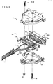
- Figure 3 is a detailed, exploded view of the software security system of the present invention as it is preferably mounted within a standard computer cable connector assembly.
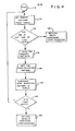
- Figure 4 is a logic flow chart illustrating the operation of the present invention.
- With reference to Figure 1, a simplified block diagram of a computer system incorporating the software security system of the present invention is shown, including a
host computer 20 having generally a central processing unit (CPU) 22, amemory unit 24, and a plurality of input/output (I/O)ports O ports host computer 20 andperipheral devices cable systems cable systems cable 40 havingconnector assemblies 42 at both ends thereof. In a preferred embodiment of the invention, a standard RS-232 interface system is utilized betweenhost computer 20 andperipherals connector assemblies 42 connecting to I/O ports pins 44, each of which are by convention accorded specified functions. Additional information concerning the RS-232 interface system may be found in an engineering standard published by the Electronic Industries Association concerning the subject. - As shown schematically in Figure 1, a
software security device 50 according to the present invention is conveniently provided within one of connector assemblies 42 intermediate an I/O port and thecommunication cable 40. According to the invention,security device 50 does not require the dedication of any of the limited number of I/O ports connector assembly 42 of an otherwise standard RS-232compatible cable assembly security device 50 does not require its own I/O port or power supply, and because it is physically hidden from view within theconnector assembly 42,security system 50 is rendered effectively transparent to users. - Of course it will be appreciated that the present invention is not limited to any
particular host computer 20, but may be used with a wide variety of commercially available host computers such as the Texas Instruments Professional Computer, Data General's Workstation Model 10, the Motorola VME-10 and the Hitachi B16. Likewise, the invention is not limited to use with the RS-232 interface system, and such system is referred to herein merely to better illustrate the practice of the invention. - With reference also to Figure 3,
connector assembly 42 generally includes a standard 25 pin RS-232connector 62, upper andlower housings appropriate fasteners 68. According to the present invention, a small printedcircuit board 70 is introduced intoconnector assembly 42 with theelectrical contact pads 71 adjacent one end thereof inserted and secured between the two rows of pins 63 ofconnector 62. A multiplexer integratedcircuit 72 of the 74C157 type commercially available from a number of different sources, four1N914 diodes K resistors board 70 to form the electrical circuit schematically represented in Figure 2. - It is common practice in using the RS-232 interface system that a substantial number of the 25 pins 63 of
connector 62 would not be utilized in any particular interconnection ofhost computer 20 to a peripheral device. As shown in Figure 2, the present invention utilizes a number of otherwise unused pins to transfer signals into and out ofsoftware security circuitry 50. Although not limiting to the invention, one such set of pins is shown as an example in Figure 2, with the pin numbers shown corresponding to the pin numbers conventionally used in the RS-232 interface system. As represented in Figure 2,pins # 2 and #3 are shown in use as input/output connectors in communication with the peripheral device throughcable 40.Pins # 23, #20 and #4 may commonly be utilized to transmit signals fromhost computer 20 to thesoftware security circuitry 50, andpins # 8, #6 and #22 may be utilized to transmit signals back cowardhost computer 20 in response thereto. Of course, the particular pins which are available in a given computer system may vary and the designer will desire to select appropriate unused pins to practice the present invention. - As shown in Figure 2, I/0
port 26 continues to perform its primary function of transmitting and receiving data alongcommunication cable 40, e.g., by utilizing pins F2 and #3 ofconnector 62 for outgoing and incoming serial data transmission, respectively. Such serial data transmission may pass through printedcircuit board 70, or alternatively (and as best shown in Figure 3),electrical leads bypass circuit board 70 and connect directly topins # 2 and #3.Electrical lead 94 of Figure 3 is provided to connect toboard 70 and therethrough topin # 7 ofconnector 62 to ground, as shown schematically in Figure 2. -
Software security circuitry 50 is conveniently mounted insidestandard connector assembly 42 such that the presence ofsecurity circuitry 50 is not visually apparent to the user. To further enhance the level of security provided bysecurity circuitry 50, it is preferred that all identifying markings on integratedcircuit 72 be removed and further that thehousings connector assembly 42 be permanently secured together, e.g., byepoxying fasteners 68 and/or the mating edges of the upper andlower housings - With reference also to Figure 4, a flow chart is provided to illustrate a form of software implemented logic which is useful in the practice of the invention. A software module is provided within the
memory unit 24 of thehost computer 20 which periodically directs that host computer 2C send out a predetermined sequence of parallel 2-bit patterns (the "inquiry pattern") topins # 4 and #23 of the RS-232connector 62. After receiving the inquiry pattern,security system 50 returns to host computer 20 a parallel 3-bit pattern from pins #6, #8 and #22 for confirmation (the "confirmation pattern"). The software module directshost computer 20 to compare the confirmation pattern with an expected pattern stored inmemory unit 24, and if a match occurs, program execution will continue. If the confirmation pattern does not match the expected pattern, or if a confirmation pattern is not received, execution of the program is terminated and a message may be displayed indicating an invalid hardware configuration. - The flow chart of Fig. 4 illustrates such a logic system. Upon the initiation of the security routine as represented in
block 110, the inquiry pattern or a portion thereof is retrieved from a table in memory, as represented inblock 112. Atblock 114, if an indication that the end of table has not been reached is received, the sequence advances to block 116. If the end of the table has been reachea, the system branches to block 126. - In
block 116, the inquiry pattern is sent from thehost computer 20 to thesecurity device 50. Inblock 118 thesecurity device 50 returns the confirmation pattern tohost computer 20.Block 120 represents the step of comparing the returned confirmation pattern to an expected pattern stored in a table in memory.Block 122 performs the logical step of determining if the compared patterns matched and if not, indicating that an invalid hardware configuration was in use, as shown inblock 124. If the compared patterns matched, the system loops back fromblock 122 to block 112 for a continuation of the process if additional portions of the inquiry pattern remain in the table in memory; or if the full inquiry pattern has been utilized, to signal that a valid hardware configuration is in use atblock 126. - As shown in Figure 2, when
pin # 23 is available for use, it is preferred that the 2-bit inquiry pattern be transmitted frompins # 4 and #23 of RS-232connector 62 and a constant "high" signal may be transmitted toIC 72 frompin # 20 to supply the necessary power thereto. To implement this embodiment of the invention, a cut may be made inconnector 100, e.g., atpoint 102, prior to assembly of the final device to isolate pins #20 and #23. In this configuration withpin # 20 serving as a constant source of power toIC 72, patterns of four distinct binary inquiry signals can be generated frompins # 4 and #23 (0,0; 0.1; 1,0; 1,1) to communicate withsecurity system 50. This embodiment of the invention is preferred with the Texas Instruments Professional Computer. - For
other host computers 20 for whichpin # 23 is either utilized or otherwise unavailable for use, the inquiry pattern is preferably transmitted frompins # 4 and #20 of RS-232connector 62. However, because no separate pin is provided to serve as a constant source of power toIC 72, the signal from one ofpins # 4 and #20 must remain in the hign state to provide power. Accordingly, in this embodiment of the invention, patterns of only three distinct binary inquiry signals can be generated. To isolatepin.# 23 from 1C 72 in this embodiment, it is preferred that a cut is made atpoint 104adjacent pin # 23 prior to the assembly of the final device. - In the preferred embodiment of the invention, integrated
circuit 72 is fabricated in CMOS technology so thatsecurity circuitry 50 can be powered by the signals provided by the RS-232connector 62 without requiring an outside source of electrical power. This feature of the invention contributes to the transparent nature ofsecurity system 50. Of course the invention is not limited to the particular 74C157 IC which was described above for purposes of illustrating the invention, as a wide variety of integrated circuits, e.g., ROMs, is available which can perform the desired function of receiving a predetermined inquiry signal and returning a predetermined confirmation signal. Likewise, the invention is not limited to the use of a 2-bit parallel inquiry signal and/or a three-bit parallel confirmation signal, as it will be apparent to those skilled in the art that many different sets and types of inquiry and confirmation signals could be utilized in the practice of the present invention. - In addition, it will be apparent to those skilled in the art that
security system 50 can be conveniently employed within aconnector assembly 42 even in situations where acommunication cable system security circuitry 50 could easily be disposed within theconnector assembly 42 which is secured to I/O port 30 without sacrificing the transparency of the security system, because it is not uncommon that aconnector assembly 42 is needed for each I/O port of a host computer, even if peripheral devices are not to be connected thereto. Accordingly, the invention is not limited to use with only those computer systems which include peripheral devices. Rather, the scope of the invention is intended to be limited only by the claims appended hereto.
Claims (18)
wherein said electronic means is mounted in said electrical cable connector means in a visually undetectable manner without otherwise affecting the function of said cable connector means.
Applications Claiming Priority (2)
| Application Number | Priority Date | Filing Date | Title |
|---|---|---|---|
| US67277984A | 1984-11-19 | 1984-11-19 | |
| US672779 | 1984-11-19 |
Publications (2)
| Publication Number | Publication Date |
|---|---|
| EP0183608A2 true EP0183608A2 (en) | 1986-06-04 |
| EP0183608A3 EP0183608A3 (en) | 1987-04-22 |
Family
ID=24699971
Family Applications (1)
| Application Number | Title | Priority Date | Filing Date |
|---|---|---|---|
| EP85402233A Withdrawn EP0183608A3 (en) | 1984-11-19 | 1985-11-19 | Software security system |
Country Status (2)
| Country | Link |
|---|---|
| EP (1) | EP0183608A3 (en) |
| JP (1) | JPS61175729A (en) |
Cited By (13)
| Publication number | Priority date | Publication date | Assignee | Title |
|---|---|---|---|---|
| FR2596545A1 (en) * | 1986-03-25 | 1987-10-02 | Hachette Classiques | Program control connector intended for home computers or for a network of interconnected computers |
| WO1988005941A1 (en) * | 1987-01-30 | 1988-08-11 | Software Activation, Inc. | Apparatus and method for regulating the use of proprietary computer software |
| FR2610744A1 (en) * | 1987-02-05 | 1988-08-12 | Microphar | METHOD AND DEVICE FOR LIMITING THE OPERATION OF SOFTWARE |
| FR2618926A1 (en) * | 1987-10-30 | 1989-02-03 | Microphar | MEMORY DEVICE FOR CONTROLLING THE USE OF SOFTWARE, OF THE KEY TYPE |
| GB2222281A (en) * | 1988-08-27 | 1990-02-28 | Simon Keith Watson | Preventing unauthorised use of copies of computer software |
| DE3914233C1 (en) * | 1989-04-29 | 1990-07-26 | Wulf 2054 Geesthacht De Harder | Computer program protection device - has generator data output connected with consisting testing stage |
| EP0388843A2 (en) * | 1989-03-23 | 1990-09-26 | Neopost Industrie | Remote enabling of software controllable features of an external device coupled with an electronic franking machine |
| FR2657705A1 (en) * | 1990-01-30 | 1991-08-02 | Microphar | MATERIAL DEVICE IDENTIFIABLE BY SOFTWARE USING COMMUNICATION MEANS, STANDARD OR NOT. |
| FR2668839A1 (en) * | 1990-11-06 | 1992-05-07 | Bull Cp8 | SECURITY DEVICE COMPRISING A MEMORY AND / OR A MICROCALCULATOR FOR INFORMATION PROCESSING MACHINES. |
| WO1994006071A1 (en) * | 1992-08-29 | 1994-03-17 | Melih Abdulhayoglu | A dongle |
| EP0371857B1 (en) * | 1988-11-30 | 1998-10-14 | Laboratoire Europeen De Recherches Electroniques Avancees | Interface with electric power supply, and computer having such an interface |
| EP0940743A1 (en) * | 1998-03-05 | 1999-09-08 | Rainbow Technologies Inc. | Compact transparent dongle device |
| US6101606A (en) * | 1996-03-22 | 2000-08-08 | Wasy Gmbh | System for securing protected software from unauthorized use in computer networks |
Families Citing this family (3)
| Publication number | Priority date | Publication date | Assignee | Title |
|---|---|---|---|---|
| JPS6370336A (en) * | 1986-09-12 | 1988-03-30 | Taiko Denki Seisakusho:Kk | Deciding method for cutoff of program execution |
| JPS63113728A (en) * | 1986-10-31 | 1988-05-18 | Sony Corp | Program controlling adapter |
| JPH0196048U (en) * | 1987-12-16 | 1989-06-26 |
Citations (9)
| Publication number | Priority date | Publication date | Assignee | Title |
|---|---|---|---|---|
| US3609697A (en) * | 1968-10-21 | 1971-09-28 | Ibm | Program security device |
| US3806882A (en) * | 1971-11-22 | 1974-04-23 | A Clarke | Security for computer systems |
| US4206962A (en) * | 1978-06-05 | 1980-06-10 | Amp Incorporated | Data/logic connector |
| EP0084441A2 (en) * | 1982-01-19 | 1983-07-27 | Tabs Limited | Method and apparatus for the protection of proprietary computer software |
| JPS58195975A (en) * | 1982-05-12 | 1983-11-15 | Canon Inc | User recognition pack of electronic instrument |
| DE3305246C1 (en) * | 1983-02-16 | 1984-05-10 | Kabelwerke Reinshagen Gmbh, 5600 Wuppertal | Flat electrical measuring cable |
| GB2145856A (en) * | 1983-08-31 | 1985-04-03 | Univ Strathclyde | Copyright protection device |
| US4562306A (en) * | 1983-09-14 | 1985-12-31 | Chou Wayne W | Method and apparatus for protecting computer software utilizing an active coded hardware device |
| WO1986002496A1 (en) * | 1984-10-16 | 1986-04-24 | Amp Incorporated | Electronic key assemblies |
-
1985
- 1985-11-18 JP JP60258425A patent/JPS61175729A/en active Pending
- 1985-11-19 EP EP85402233A patent/EP0183608A3/en not_active Withdrawn
Patent Citations (9)
| Publication number | Priority date | Publication date | Assignee | Title |
|---|---|---|---|---|
| US3609697A (en) * | 1968-10-21 | 1971-09-28 | Ibm | Program security device |
| US3806882A (en) * | 1971-11-22 | 1974-04-23 | A Clarke | Security for computer systems |
| US4206962A (en) * | 1978-06-05 | 1980-06-10 | Amp Incorporated | Data/logic connector |
| EP0084441A2 (en) * | 1982-01-19 | 1983-07-27 | Tabs Limited | Method and apparatus for the protection of proprietary computer software |
| JPS58195975A (en) * | 1982-05-12 | 1983-11-15 | Canon Inc | User recognition pack of electronic instrument |
| DE3305246C1 (en) * | 1983-02-16 | 1984-05-10 | Kabelwerke Reinshagen Gmbh, 5600 Wuppertal | Flat electrical measuring cable |
| GB2145856A (en) * | 1983-08-31 | 1985-04-03 | Univ Strathclyde | Copyright protection device |
| US4562306A (en) * | 1983-09-14 | 1985-12-31 | Chou Wayne W | Method and apparatus for protecting computer software utilizing an active coded hardware device |
| WO1986002496A1 (en) * | 1984-10-16 | 1986-04-24 | Amp Incorporated | Electronic key assemblies |
Non-Patent Citations (3)
| Title |
|---|
| IBM TECHNICAL DISCLOSURE BULLETIN, vol. 16, no. 3, August 1973, page 918, Armonk, US; C. B. GLOWIENKA: "Solid-state connecting arrangement" * |
| IBM TECHNICAL DISCLOSURE BULLETIN, vol. 24, no. 6, November 1981, pages 2949-2950, Armonk, US; J. H. DODGE et al.: "Electrical isolation circuit for interconnected systems" * |
| PATENTS ABSTRACTS OF JAPAN, vol. 8, no. 45 (P-257)[1482], 28th February 1984; & JP-A-58 195 975 (CANON K.K.) 15-11-1983 * |
Cited By (19)
| Publication number | Priority date | Publication date | Assignee | Title |
|---|---|---|---|---|
| FR2596545A1 (en) * | 1986-03-25 | 1987-10-02 | Hachette Classiques | Program control connector intended for home computers or for a network of interconnected computers |
| WO1988005941A1 (en) * | 1987-01-30 | 1988-08-11 | Software Activation, Inc. | Apparatus and method for regulating the use of proprietary computer software |
| FR2610744A1 (en) * | 1987-02-05 | 1988-08-12 | Microphar | METHOD AND DEVICE FOR LIMITING THE OPERATION OF SOFTWARE |
| EP0279733A1 (en) * | 1987-02-05 | 1988-08-24 | MICROPHAR, Sàrl dite: | Method and device for limiting the use of a computer programme |
| FR2618926A1 (en) * | 1987-10-30 | 1989-02-03 | Microphar | MEMORY DEVICE FOR CONTROLLING THE USE OF SOFTWARE, OF THE KEY TYPE |
| EP0314530A1 (en) | 1987-10-30 | 1989-05-03 | MICROPHAR, Sàrl dite: | A key-type soft ware usage control device with memory |
| GB2222281A (en) * | 1988-08-27 | 1990-02-28 | Simon Keith Watson | Preventing unauthorised use of copies of computer software |
| EP0371857B1 (en) * | 1988-11-30 | 1998-10-14 | Laboratoire Europeen De Recherches Electroniques Avancees | Interface with electric power supply, and computer having such an interface |
| EP0388843A2 (en) * | 1989-03-23 | 1990-09-26 | Neopost Industrie | Remote enabling of software controllable features of an external device coupled with an electronic franking machine |
| EP0388843A3 (en) * | 1989-03-23 | 1991-07-31 | Neopost Industrie | Remote enabling of software controllable features of an external device coupled with an electronic franking machine |
| DE3914233C1 (en) * | 1989-04-29 | 1990-07-26 | Wulf 2054 Geesthacht De Harder | Computer program protection device - has generator data output connected with consisting testing stage |
| FR2657705A1 (en) * | 1990-01-30 | 1991-08-02 | Microphar | MATERIAL DEVICE IDENTIFIABLE BY SOFTWARE USING COMMUNICATION MEANS, STANDARD OR NOT. |
| EP0440545A1 (en) * | 1990-01-30 | 1991-08-07 | MICROPHAR Société anonyme dite | Hardware device identifiable by a program using standard or non-standard communication means |
| FR2668839A1 (en) * | 1990-11-06 | 1992-05-07 | Bull Cp8 | SECURITY DEVICE COMPRISING A MEMORY AND / OR A MICROCALCULATOR FOR INFORMATION PROCESSING MACHINES. |
| EP0485275A1 (en) * | 1990-11-06 | 1992-05-13 | Bull Cp8 | Security device with a memory and/or a microprocessor for data processing machines |
| WO1992008181A1 (en) * | 1990-11-06 | 1992-05-14 | Bull Cp8 | Security device having a memory and/or a microcomputer for data processing hardware |
| WO1994006071A1 (en) * | 1992-08-29 | 1994-03-17 | Melih Abdulhayoglu | A dongle |
| US6101606A (en) * | 1996-03-22 | 2000-08-08 | Wasy Gmbh | System for securing protected software from unauthorized use in computer networks |
| EP0940743A1 (en) * | 1998-03-05 | 1999-09-08 | Rainbow Technologies Inc. | Compact transparent dongle device |
Also Published As
| Publication number | Publication date |
|---|---|
| EP0183608A3 (en) | 1987-04-22 |
| JPS61175729A (en) | 1986-08-07 |
Similar Documents
| Publication | Publication Date | Title |
|---|---|---|
| EP0183608A2 (en) | Software security system | |
| EP1141804B1 (en) | A control device for a computer, use of a control device, a computer comprising a control device, and a method of connecting and disconnecting units in a computer | |
| US5093862A (en) | Data carrier-controlled terminal in a data exchange system | |
| US4484306A (en) | Method and apparatus for controlling access in a data transmission system | |
| US4562306A (en) | Method and apparatus for protecting computer software utilizing an active coded hardware device | |
| US5434395A (en) | Method and device for effecting a transaction between a first and at least one second data carrier and carrier used for this purpose | |
| US5984508A (en) | System, method and article of manufacture for product return of software and other information | |
| CN102257536B (en) | The access control system and access control method of personnel's conveyer control system | |
| US5588146A (en) | Method for the acquisition of software and data-processing system to implement the method | |
| JP3357048B2 (en) | Method and interface for interfacing a portable data carrier to a host processor | |
| CA2449527C (en) | Distributing frame for mutually connecting optical connection lines | |
| AU687312B2 (en) | Card interface | |
| US6438625B1 (en) | System and method for automatically identifying slots in a backplane | |
| CN1983245A (en) | System and method for configuring information handling system integrated circuits | |
| US20020010856A1 (en) | IC, IC-mounted electronic device, debugging method and IC debugger | |
| US20020007425A1 (en) | Authenticating peripherals based on a predetermined code | |
| US5414753A (en) | Number assignment module setting system for portable telephone set | |
| US5297200A (en) | Computer security system | |
| CN107943260A (en) | Semiconductor equipment, the method and semiconductor system for controlling semiconductor equipment | |
| US6442508B1 (en) | Method for internal mechanical component configuration detection | |
| US6854024B2 (en) | Identification of a peripheral connection state with a universal serial bus | |
| CN109582320A (en) | Write yard method and terminal device | |
| US6968995B1 (en) | Integrated circuit for protocol control | |
| EP1178406A1 (en) | Automatic concealment of product serialization information | |
| US5719382A (en) | Display peripheral incorporating a wedge interface |
Legal Events
| Date | Code | Title | Description |
|---|---|---|---|
| PUAI | Public reference made under article 153(3) epc to a published international application that has entered the european phase |
Free format text: ORIGINAL CODE: 0009012 |
|
| STAA | Information on the status of an ep patent application or granted ep patent |
Free format text: STATUS: THE APPLICATION HAS BEEN PUBLISHED |
|
| AK | Designated contracting states |
Kind code of ref document: A2 Designated state(s): DE FR GB IT NL |
|
| PUAL | Search report despatched |
Free format text: ORIGINAL CODE: 0009013 |
|
| AK | Designated contracting states |
Kind code of ref document: A3 Designated state(s): DE FR GB IT NL |
|
| 18D | Application deemed to be withdrawn |
Effective date: 19871223 |
|
| RIN1 | Information on inventor provided before grant (corrected) |
Inventor name: BARTON, BRIAN F. Inventor name: GOEN, WILLIAM J. Inventor name: DOLLHOFF, TERRY L. Inventor name: VAN DYKE, PHILLIP L. Inventor name: HANSEN, HAROLD R. JR. |