EP0182001A2 - Method and apparatus for making a flexible corrugated tube, and a flexible corrugated tube made by this method - Google Patents
Method and apparatus for making a flexible corrugated tube, and a flexible corrugated tube made by this method Download PDFInfo
- Publication number
- EP0182001A2 EP0182001A2 EP85107929A EP85107929A EP0182001A2 EP 0182001 A2 EP0182001 A2 EP 0182001A2 EP 85107929 A EP85107929 A EP 85107929A EP 85107929 A EP85107929 A EP 85107929A EP 0182001 A2 EP0182001 A2 EP 0182001A2
- Authority
- EP
- European Patent Office
- Prior art keywords
- shaft
- rotation
- wave
- mold
- tube
- Prior art date
- Legal status (The legal status is an assumption and is not a legal conclusion. Google has not performed a legal analysis and makes no representation as to the accuracy of the status listed.)
- Granted
Links
Images


Classifications
-
- F—MECHANICAL ENGINEERING; LIGHTING; HEATING; WEAPONS; BLASTING
- F16—ENGINEERING ELEMENTS AND UNITS; GENERAL MEASURES FOR PRODUCING AND MAINTAINING EFFECTIVE FUNCTIONING OF MACHINES OR INSTALLATIONS; THERMAL INSULATION IN GENERAL
- F16L—PIPES; JOINTS OR FITTINGS FOR PIPES; SUPPORTS FOR PIPES, CABLES OR PROTECTIVE TUBING; MEANS FOR THERMAL INSULATION IN GENERAL
- F16L11/00—Hoses, i.e. flexible pipes
- F16L11/14—Hoses, i.e. flexible pipes made of rigid material, e.g. metal or hard plastics
- F16L11/16—Hoses, i.e. flexible pipes made of rigid material, e.g. metal or hard plastics wound from profiled strips or bands
-
- B—PERFORMING OPERATIONS; TRANSPORTING
- B21—MECHANICAL METAL-WORKING WITHOUT ESSENTIALLY REMOVING MATERIAL; PUNCHING METAL
- B21C—MANUFACTURE OF METAL SHEETS, WIRE, RODS, TUBES OR PROFILES, OTHERWISE THAN BY ROLLING; AUXILIARY OPERATIONS USED IN CONNECTION WITH METAL-WORKING WITHOUT ESSENTIALLY REMOVING MATERIAL
- B21C37/00—Manufacture of metal sheets, bars, wire, tubes or like semi-manufactured products, not otherwise provided for; Manufacture of tubes of special shape
- B21C37/06—Manufacture of metal sheets, bars, wire, tubes or like semi-manufactured products, not otherwise provided for; Manufacture of tubes of special shape of tubes or metal hoses; Combined procedures for making tubes, e.g. for making multi-wall tubes
- B21C37/12—Making tubes or metal hoses with helically arranged seams
- B21C37/121—Making tubes or metal hoses with helically arranged seams with non-welded and non-soldered seams
-
- B—PERFORMING OPERATIONS; TRANSPORTING
- B21—MECHANICAL METAL-WORKING WITHOUT ESSENTIALLY REMOVING MATERIAL; PUNCHING METAL
- B21C—MANUFACTURE OF METAL SHEETS, WIRE, RODS, TUBES OR PROFILES, OTHERWISE THAN BY ROLLING; AUXILIARY OPERATIONS USED IN CONNECTION WITH METAL-WORKING WITHOUT ESSENTIALLY REMOVING MATERIAL
- B21C37/00—Manufacture of metal sheets, bars, wire, tubes or like semi-manufactured products, not otherwise provided for; Manufacture of tubes of special shape
- B21C37/06—Manufacture of metal sheets, bars, wire, tubes or like semi-manufactured products, not otherwise provided for; Manufacture of tubes of special shape of tubes or metal hoses; Combined procedures for making tubes, e.g. for making multi-wall tubes
- B21C37/12—Making tubes or metal hoses with helically arranged seams
- B21C37/124—Making tubes or metal hoses with helically arranged seams the tubes having a special shape, e.g. with corrugated wall, flexible tubes
Definitions
- the invention relates to a method and a device for producing a flexible corrugated tube by helically winding a thin metal strip with shafts running parallel to its longitudinal direction, at least one shaft of two successive turns being nested and connected to one another.
- Such flexible corrugated pipes are used in the heating, air conditioning and ventilation areas.
- a very thin, narrow, flat metal strip is first pre-corrugated in a profiling system with the aid of several shaping rollers in such a way that the corrugation valleys and wave crests run parallel to the longitudinal direction of the strip.
- This pre-corrugated tape is wound up and can then be processed into a tube on a tube winding machine.
- the tube is produced in the tube winding machine by helically winding the pre-corrugated strip, the edges of adjacent turns being connected to one another will.
- the most varied types of connection are known, for example gluing, welding, folding, depressing a shaft crest in places or the like. More.
- the object of the invention is therefore to propose a method of the type mentioned at the outset, with which a water-tight and gas-tight flexible corrugated pipe, for example also on a construction site, can be produced in a simple and material-saving manner, which has great flexibility.
- interlocking shaft is initially circumferentially compressed in such a way that the shaft flanks of the shaft lie flat on top of one another, that the pressed shaft is rolled up from the apex of the shaft to the shaft base and that the rolled-up shaft is then pressed into the shaft base .
- a device for performing the method with a Winding device for guiding the finished tube and with a pair of infeed rollers arranged at the entry point of the strip into the winding device and acting on the two broad sides of the strip, which mutually connect the adjacent turns in the tube one infeed roller about an axis of rotation inside and the other infeed roller is arranged rotatably about an axis of rotation outside of the winding device, according to the invention a shaping tool which compresses and rolls together the interlocking shaft of the incoming strip is arranged on the axis of rotation of the upper feed roller.
- the molding tool is advantageously designed as a continuous tool with a molding gap for the shaft.
- the mold gap of the molding tool is preferably curved in the shape of an arc, the center or centers of curvature being located above the lower feed roller.
- the radius of curvature advantageously corresponds to the curvature of the mold gap approximately the radius of the pipe to be manufactured.
- the mold is initially conical to a narrow gap from its inlet to its outlet and then narrowing like a screw to an approximately round opening.
- the molding tool is preferably arranged on the axis of rotation of the upper feed roller in such a way that it is a round opening trained outlet lies approximately on the connecting line of the axes of rotation of the two inlet rollers and that the inlet of the molding tool is in front of this connecting line, as seen in the direction of entry of the belt.
- Press rings for pressing the deformed shaft into the shaft base are preferably arranged on the axes of rotation of the inlet rollers.
- the pressing rings are advantageously arranged on the outlet side of the winding device at a distance from the molding tool, which is equal to the distance between the deformed shafts of the tube.
- the method according to the invention first compresses the circumferentially in the axial direction and then from the crest of the shaft Rolled nested wave into the bottom of the shaft pressed into the bottom of the shaft.
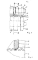
- a device for producing a flexible corrugated tube by helically winding a metal strip 4 has a winding device 1 for guiding the finished tube 2.
- the winding device 1 has guide rollers 3 arranged on a circle for guiding the tube, which are rotatable about axes, not shown.
- a pair of entry rollers 5 and 6 is arranged, the upper entry roller 5 being rotatable about an axis of rotation 7 which is located within the winding device 1, and the bottom entry roller 6 being arranged to be rotatable about an axis of rotation 8 , which is arranged outside the winding device 1.
- the inlet rollers 5 and 6 can be driven by a drive, not shown.
- the inlet rollers act on the two broad sides of the supplied tape 4 and bring about the mutual connection of the turns adjacent in the tube 2.
- the tape 4 is fed to the pair of feed rollers 5 and 6 via an adjustable pressure roller 9 arranged in front of the winding device. Further pairs of feed rollers 10 are arranged in front of the pressure roller 9.
- connection of the individual winding layers of the tube to one another takes place in that first of all one shaft two at a time other turns are placed one inside the other, the nested shaft is compressed all around in the axial direction of the tube in such a way that the wave flanks of the shaft lie flat on top of one another, so that the flattened wave is rolled up from the apex of the shaft to the bottom of the shaft and that the rolled-up shaft is then pressed into the bottom of the shaft.
- the infeed rollers 5 and 6 have a profile corresponding to the band 4 fed.
- Fig o 2 and 3 is on the top axis of rotation 7 of the upper input roller 5, a compressing and rolling said nested waves of the incoming strip 4 effecting mold 11 having a mold gap 11a (FIG. 4).
- the molding gap 11a of the molding tool is curved in an arc shape, the center of curvature being above the lower feed roller 6 and above the upper axis 7.
- the molding tool 11 has a clamping device 12, so that the molding tool is displaceably and rotatably arranged on the axis of rotation 7 and can be fixed on the axis of rotation 7 with the aid of the clamping device 12.
- the molding tool 11 is designed as a continuous tool for the shaft to be deformed which is to be deformed.
- the mold 11 is from its inlet 13 to its outlet 14 (Fig. 5) initially conical to a narrow gap and then narrowing like a screw to an approximately round opening.
- the molding tool is arranged on the axis of rotation 7 of the upper infeed roller 5 such that its outlet 14, which is designed as a round opening, lies approximately on the connecting line 15 of the axes of rotation 7 and 8 of the two infeed rollers 5 and 6 and that the inlet 13 of the molding tool in the infeed direction of the belt 4, indicated by the arrow 16, lies before this connecting line.
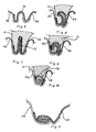
- FIG. 6 shows in the cutting direction 16 of the strip in different sections the deformation of the interlocking shafts of the strip and the shape of the molding tool.
- a shaft of the incoming strip 4b is inserted into a shaft of the already wound strip 4a immediately before the inlet 13 of the molding tool 11.
- the shaft 4c lying one inside the other now runs into the inlet 13 of the molding tool 11, which initially narrows from its inlet 13 to a narrow gap 17, as shown in FIG. 7.
- the incoming shaft 4c is compressed circumferentially in the axial direction in such a way that the shaft flanks of the shaft 4c lie flat on one another, as shown in FIG. 7.
- the mold gap of the molding tool 11 then narrows like a screw according to FIGS. 8 to 10 to a round opening 18, so that the tapering, flat-pressed shaft 4c, rolled up from the apex of the shaft toward the shaft base, leaves the outlet 14 of the molding tool, as shown in FIG. 10 is shown.
- press rings 19 and 20 are rotatably arranged. These press rings press the rolled-up shaft 4c into the shaft base, as shown in FIG. 11.
- a flexible corrugated pipe manufactured in this way is water and gas tight. This is brought about by the fact that the nested shaft is pressed flat and rolled into a very small space and pressed into the bottom of the shaft. As a result, the manufactured tube shrinks in the axial direction by a wave width in relation to the fed band 4.
- the shrunk wave extends spirally around the tube and acts because of the material concentration like a spirally guided wire inserted in the tube, so that the tube has an increased crest pressure resistance having.
- the turns are securely connected to one another in the axial and tangential directions by the material concentration. Furthermore, only a small amount of material is used because only one wave width is lost.
Abstract
Description
Die Erfindung bezieht sich auf ein Verfahren und eine Vorrichtung zum Herstellen eines flexiblen Wellrohres durch schraubenlinienförmiges Wickeln eines dünnen Metallbandes, mit parallel zu seiner Längsrichtung verlaufenden Wellen, wobei mindestens jeweils eine Welle zweier aufeinanderfolgender Windungen ineinandergelegt und miteinander verbunden werden.The invention relates to a method and a device for producing a flexible corrugated tube by helically winding a thin metal strip with shafts running parallel to its longitudinal direction, at least one shaft of two successive turns being nested and connected to one another.
Derartige flexible Wellrohre werden im Heizungs-, Klima- und Lüftungsbereich eingesetzt. Zur Herstellung dieser Wellrohre wird zunächst ein sehr dünnes, schmales, flaches Metallband in einer Profilieranlage mit Hilfe von mehreren Formrollen derart vorgewellt, daß die Wellentäler und Wellenberge parallel zur Längsrichtung des Bandes verlaufen. Dieses vorgewellte Band wird aufgespult und kann dann auf einer Rohrwickelmaschine zu einem Rohr verarbeitet werden.Such flexible corrugated pipes are used in the heating, air conditioning and ventilation areas. To manufacture these corrugated pipes, a very thin, narrow, flat metal strip is first pre-corrugated in a profiling system with the aid of several shaping rollers in such a way that the corrugation valleys and wave crests run parallel to the longitudinal direction of the strip. This pre-corrugated tape is wound up and can then be processed into a tube on a tube winding machine.
Die Herstellung des Rohres erfolgt in der Rohrwickelmaschine durch schraubenlinienförmiges Wickeln des vorgewellten Bandes, wobei die Ränder benachbarter Windungen miteinander verbunden werden. Es sind die verschiedensten Arten der Verbindung bekannt, beispielsweise Verkleben, Verschweißen, Falzen, stellenweises Niederdrücken eines Wellenscheitels od. dgl. mehr.The tube is produced in the tube winding machine by helically winding the pre-corrugated strip, the edges of adjacent turns being connected to one another will. The most varied types of connection are known, for example gluing, welding, folding, depressing a shaft crest in places or the like. More.
Soll ein wasser- und gasdichtes Rohr hergestellt werden, so sind an die Verbindungen der einzelnen Windungen sehr große Anforderungen zu stellen. Dies ist bei den bisher bekannten Verfahren sehr schwierig und nur mit großem Aufwand zu erzielen, indem beispielsweise das Rohr mehrlagig gewickelt wird. Nachteilig ist weiterhin, daß dadurch die Flexibilität des Rohres beeinträchtigt wird.If a water- and gas-tight pipe is to be produced, the connections of the individual windings have to meet very high requirements. This is very difficult with the previously known methods and can only be achieved with great effort, for example by winding the tube in multiple layers. Another disadvantage is that this affects the flexibility of the tube.
Die Aufgabe der Erfindung besteht daher darin, ein Verfahren der eingangs genannten Art vorzuschlagen, mit dem auf einfache und materialsparende Weise kostengünstig ein wasser- und gasdichtes flexibles Wellrohr, beispielsweise auch auf einer Baustelle, hergestellt werden kann, das eine große Flexibilität hat.The object of the invention is therefore to propose a method of the type mentioned at the outset, with which a water-tight and gas-tight flexible corrugated pipe, for example also on a construction site, can be produced in a simple and material-saving manner, which has great flexibility.
Diese Aufgabe wird dadurch gelöst, daß zunächst die ineinanderliegende Welle in axialer Richtung umlaufend derart zusammengepreßt wird, daß die Wellenflanken der Welle flach aufeinanderliegen, daß die flachgepreßte Welle vom Wellenscheitel aus zum Wellengrund hin zusammengerollt wird und daß die zusammengerollte Welle anschließend in den Wellengrund eingepreßt wird.This object is achieved in that the interlocking shaft is initially circumferentially compressed in such a way that the shaft flanks of the shaft lie flat on top of one another, that the pressed shaft is rolled up from the apex of the shaft to the shaft base and that the rolled-up shaft is then pressed into the shaft base .
Bei einer Vorrichtung zur Durchführung des Verfahrens mit einer Wickeleinrichtung zum Führen des gefertigten Rohres und mit einem an der Einlaufstelle des Bandes in die Wickeleinrichtung angeordneten, an den beiden Breitseiten des Bandes angreifenden, die gegenseitige Verbindung der im Rohr benachbarten Windungen bewirkenden Einlaufrollenpaar, wobei die eine Einlaufrolle um eine Drehachse innerhalb und die andere Einlaufrolle um eine Drehachse außerhalb der Wickeleinrichtung drehbar angeordnet ist, ist erfindungsgemäß auf der Drehachse der oberen Einlaufrolle eine das Zusammenpressen und Zusammenrollen der ineinanderliegenden Welle des zulaufenden Bandes bewirkendes Formwerkzeug festlegbar angeordnet.In a device for performing the method with a Winding device for guiding the finished tube and with a pair of infeed rollers arranged at the entry point of the strip into the winding device and acting on the two broad sides of the strip, which mutually connect the adjacent turns in the tube, one infeed roller about an axis of rotation inside and the other infeed roller is arranged rotatably about an axis of rotation outside of the winding device, according to the invention a shaping tool which compresses and rolls together the interlocking shaft of the incoming strip is arranged on the axis of rotation of the upper feed roller.
Vorteilhaft ist das Formwerkzeug als Durchlaufwerkzeug mit einem Formspalt für die Welle ausgebildet. Vorzugsweise ist der Formspalt des Formwerkzeuges bogenförmig gekrümmt ausgebildet, wobei der oder die Krummungsmittelpunkte oberhalb der unteren Einlaufrolle liegen. Vorteilhaft entspricht der Krümmungsradius der Krümmung des Formspaltes etwa dem Radius des zu fertigenden Rohres. Vorzugsweise ist das Formwerkzeug von seinem Einlauf zu seinem Auslauf hin zunächst sich konisch zu einem schmalen Spalt und anschließend sich schneckenartig zu einer etwa runden Öffnung verengend ausgebildet.The molding tool is advantageously designed as a continuous tool with a molding gap for the shaft. The mold gap of the molding tool is preferably curved in the shape of an arc, the center or centers of curvature being located above the lower feed roller. The radius of curvature advantageously corresponds to the curvature of the mold gap approximately the radius of the pipe to be manufactured. Preferably, the mold is initially conical to a narrow gap from its inlet to its outlet and then narrowing like a screw to an approximately round opening.
Vorzugsweise ist das Formwerkzeug derartig auf der Drehachse der oberen Einlaufrolle angeordnet, daß sein als runde Öffnung ausgebildeter Auslauf etwa auf der Verbindungslinie der Drehachsen der beiden Einlaufrollen liegt und daß der Einlauf des Formwerkzeuges in Einlaufrichtung des Bandes gesehen vor dieser Verbindungslinie liegt.The molding tool is preferably arranged on the axis of rotation of the upper feed roller in such a way that it is a round opening trained outlet lies approximately on the connecting line of the axes of rotation of the two inlet rollers and that the inlet of the molding tool is in front of this connecting line, as seen in the direction of entry of the belt.
Vorzugsweise sind auf den Drehachsen der Einlaufrollen Preßringe zum Einpressen der verformten Welle in den Wellengrund angeordnet.Press rings for pressing the deformed shaft into the shaft base are preferably arranged on the axes of rotation of the inlet rollers.
Vorteilhaft sind die Preßringe an der Auslaufseite der Wickeleinrichtung im Abstand vom Formwerkzeug angeordnet, der gleich dem Abstand der verformten Wellen des Rohres ist.The pressing rings are advantageously arranged on the outlet side of the winding device at a distance from the molding tool, which is equal to the distance between the deformed shafts of the tube.
Bei einem flexiblen Wellrohr aus einem schraubenlinigförmig gewickelten dünnen Metallband mit parallel zu seiner Längsrichtung verlaufenden Wellen, bei dem mindestens jeweils eine Welle zweier aufeinanderfolgender Windungen ineinandergelegt und miteinander verbunden werden, ist nach dem erfindungsgemäßen Verfahren zunächst die in axialer Richtung umlaufend zusammengepresste und anschließend vom Wellenscheitel aus zum Wellengrund zusammengerollte ineinanderliegende Welle in den Wellengrund eingepreßt.In the case of a flexible corrugated tube made of a helically wound thin metal strip with shafts running parallel to its longitudinal direction, in which at least one shaft of two successive turns are interlocked and connected to one another, the method according to the invention first compresses the circumferentially in the axial direction and then from the crest of the shaft Rolled nested wave into the bottom of the shaft pressed into the bottom of the shaft.
Die Erfindung ist in den Zeichnungen beispielhaft dargestellt. Es zeigen:
- Fig. 1 eine erfindungsgemäße Vorrichtung in Ansicht auf die Stirnseite der Einlaufrollen,
- Fig. 2 die Einlaufrollen mit Formwerkzeug in Seitenansicht in auseinandergezogener Stellung,
- Fig. 3 das Einlaufrollenpaar mit Formwerkzeug in vergrößertem Detail,
- Fig. 4 das Einlaufrollenpaar mit Formwerkzeug im Querschnitt nach IV-IV der Fig. 2,
- Fig. 5 das Formwerkzeug in Seitenansicht im vergrößerten Detail,
- Fig. 6 die ineinanderliegende Welle vor Einlauf in das Formwerkzeug im Schnitt nach VI-VI der Fig. 5,
- Fig. 7 die flachgepreßte Welle im Schnitt durch das Formwerkzeug nach VII-VII der Fig. 5,
- Fig. 8 die gebogene, flachgepreßte Welle im Schnitt durch das Formwerkzeug nach VIII-VIII der Fig. 5,
- Fig. 9 die teilweise zusammengerollte Welle im Schnitt durch das Formwerkzeug nach IX-IX der Fig. 5,
- Fig. 10 die zusammengerollte Welle im Schnitt durch das Formwerkzeug nach X-X der Fig. 5 und
- Fig. 11 die in den Wellengrund eingepreßte Welle.
- 1 shows a device according to the invention in a view of the end face of the feed rollers,
- 2 the infeed rollers with mold in side view in an exploded position,
- 3 shows the pair of infeed rollers with molding tool in enlarged detail,
- 4 shows the pair of infeed rollers with mold in cross section according to IV-IV of FIG. 2,
- 5 the molding tool in side view in enlarged detail,
- 6 shows the nested shaft before it enters the molding tool in section along VI-VI of FIG. 5,
- 7 shows the flattened shaft in section through the molding tool according to VII-VII of FIG. 5,
- 8 shows the curved, flat-pressed shaft in section through the molding tool according to VIII-VIII of FIG. 5,
- 9 shows the partially rolled-up shaft in section through the molding tool according to IX-IX of FIG. 5,
- Fig. 10, the rolled-up shaft in section through the molding tool according to XX of Fig. 5 and
- 11 shows the shaft pressed into the bottom of the shaft.
Nach Fig. 1 weist eine Vorrichtung zum Herstellen eines flexiblen Wellrohres durch schraubenlinienförmiges Wickeln eines Metallbandes 4 eine Wickeleinrichtung 1 zum Führen des gefertigten Rohres 2 auf. Die Wickeleinrichtung 1 hat zur Führung des Rohres auf einem Kreis angeordnete Führungsrollen 3, die um nicht dargestellte Achsen drehbar sind. An der Einlaufstelle des Bandes 4 in die Wickeleinrichtung 1 ist ein Einlaufrollenpaar 5 und 6 angeordnet, wobei die obere Einlaufrolle 5 um eine Drehachse 7 drehbar ist, die innerhalb der Wickeleinrichtung 1 sitzt, und wobei die untere Einlaufrolle 6 um eine Drehachse 8 drehbar angeordnet ist, die außerhalb der Wickeleinrichtung 1 angeordnet ist.1, a device for producing a flexible corrugated tube by helically winding a
Die Einlaufrollen 5 und 6 sind durch einen nichtgezeigten Antrieb antreibbar. Die Einlaufrollen greifen an den beiden Breitseiten des zugeführten Bandes 4 an und bewirken die gegenseitige Verbindung der im Rohr 2 benachbarten Windungen.The
Das Band 4 wird über eine vor der Wickeleinrichtung angeordnete verstellbare Andruckrolle 9 dem Einlaufrollenpaar 5 und 6 zugeführt. Vor der Andruckrolle 9 sind weitere Zuführrollenpaare 10 angeordnet.The
Die Verbindung der einzelnen Windungslagen des Rohres miteinander erfolgt dadurch, daß zunächst jeweils eine Welle zweier aufeinanderfolgender Windungen ineinandergelegt wird, die ineinanderliegende Welle in axialer Richtung des Rohres umlaufend derart zusammengepreßt wird, daß die Wellenflanken der Welle flach aufeinanderliegen, daß die flachgepreßte Welle vom Wellenscheitel aus zum Wellengrund hin zusammengerollt wird und daß die zusammengerollte Welle anschließend in den Wellengrund eingepreßt wird.The connection of the individual winding layers of the tube to one another takes place in that first of all one shaft two at a time other turns are placed one inside the other, the nested shaft is compressed all around in the axial direction of the tube in such a way that the wave flanks of the shaft lie flat on top of one another, so that the flattened wave is rolled up from the apex of the shaft to the bottom of the shaft and that the rolled-up shaft is then pressed into the bottom of the shaft.
Wie die Fig. 2 bis 4 zeigen, weisen die Einlaufrollen 5 und 6 eine dem zugeführten Band 4 entsprechende Profilierung auf. Wie insbesondere die Figo 2 und 3 zeigen, ist auf der oberen Drehachse 7 der oberen Einlaufrolle 5 ein das Zusammenpressen und Zusammenrollen der ineinanderliegenden Wellen des zulaufenden Bandes 4 bewirkendes Formwerkzeug 11 mit einem Formspalt 11a (Fig. 4) angeordnet. Der Formspalt 11a des Formwerkzeuges ist bogenförmig gekrümmt, wobei der Krümmungsmittelpunkt oberhalb der unteren Einlaufrolle 6 und oberhalb der oberen Achse 7 liegt.As shown in FIGS. 2 to 4, the
Wie insbesondere die Fig. 4 zeigt, hat das Formwerkzeug 11 eine Klemmvorrichtung 12, so daß das Formwerkzeug auf der Drehachse 7 verschiebbar und verdrehbar angeordnet ist und mit Hilfe der Klemmvorrichtung 12 auf der Drehachse 7 festlegbar ist.As shown in FIG. 4 in particular, the
Das Formwerkzeug 11 ist als Durchlaufwerkzeug für die ineinanderliegende, zu verformende Welle ausgebildet. Das Formwerkzeug 11 ist von seinem Einlauf 13 zu seinem Auslauf 14 hin (Fig. 5) zunächst sich konisch zu einem schmalen Spalt und anschließend sich schneckenartig zu einer etwa runden Öffnung verengend ausgebildet.The
Wie die Fig. 4 zeigt, ist das Formwerkzeug derart auf der Drehachse 7 der oberen Einlaufrolle 5 angeordnet, daß sein als runde Öffnung ausgebildeter Auslauf 14 etwa auf der Verbindungslinie 15 der Drehachsen 7 und 8 der beiden Einlaufrollen 5 und 6 liegt und daß der Einlauf 13 des Formwerkzeuges in der mit dem Pfeil 16 bezeichneten Einlaufrichtung des Bandes 4 gesehen vor dieser Verbindungslinie liegt.As shown in FIG. 4, the molding tool is arranged on the axis of
Die Fig. 5 bis 10 zeigen in Einlaufrichtung 16 des Bandes in unterschiedlichen Schnitten die Verformung der ineinanderliegenden Wellen des Bandes, sowie die Form des Formwerkzeuges. Nach Fig. 6 wird unmittelbar vor dem Einlauf 13 des Formwerkzeuges 11 eine Welle des zulaufenden Bandes 4b in eine Welle des bereits gewickelten Bandes 4a eingelegt. Die so ineinanderliegende Welle 4c läuft nun in den Einlauf 13 des Formwerkzeuges 11 ein, das sich zunächst von seinem Einlauf 13 zu einem schmalen Spalt 17 verengt, wie dies in Fig. 7 dargestellt ist. Dadurch wird die einlaufende Welle 4c in axialer Richtung umlaufend derart zusammengepreßt, daß die Wellenflanken der Welle 4c flach aufeinanderliegen, wie dies die Fig. 7 zeigt.5 to 10 show in the
Der Formspalt des Formwerkzeuges 11 verengt sich anschließend schneckenartig entsprechend den Fig. 8 bis 10 zu einer runden Öffnung 18, so daß die zulaufende, flachgepreßte Welle 4c vom Wellenscheitel aus zum Wellengrund hin zusammengerollt den Auslauf 14 des Formwerkzeuges verläßt, wie dies in Fig.10 dargestellt ist.The mold gap of the
Wie die Fig. 2 zeigt, sind an der Auslaufseite der Wickeleinrichtung 1 im Abstand von einer Bandbreite des Bandes 4, verringert um zwei Wellenbreiten, vom Formwerkzeug 11 auf den Drehachsen 7 und 8 des Einlaufrollenpaares 5 und 6 Preßringe 19 und 20 drehbar angeordnet. Diese Preßringe pressen die zusammengerollte Welle 4c in den Wellengrund ein, wie dies in Fig. 11 gezeigt ist.2 shows, on the outlet side of the winding device 1 at a distance from a bandwidth of the
Ein so hergestelltes flexibles Wellrohr ist wasser- und gasdicht. Dies wird dadurch bewirkt, daß die ineinanderliegende Welle flachgepreßt und auf sehr engem Raum gerollt in den Wellengrund eingepreßt wird. Dadurch schrumpft das gefertigte Rohr in axialer Richtung um eine Wellenbreite in Bezug zu dem zugeführten Band 4. Die geschrumpfte Welle zieht sich spiralförmig um das Rohr und wirkt wegen der Materialkonzentration wie ein im Rohr eingelegter, spiralförmig geführter Draht, so daß das Rohr eine erhöhte Scheiteldruckfestigkeit aufweist. Darüber hinaus sind die Windungen in axialer und tangentialer Richtung durch die Materialkonzentration sicher miteinander verbunden. Weiterhin tritt nur ein geringer Materialverbrauch auf, da lediglich eine Wellenbreite verlorengeht.A flexible corrugated pipe manufactured in this way is water and gas tight. This is brought about by the fact that the nested shaft is pressed flat and rolled into a very small space and pressed into the bottom of the shaft. As a result, the manufactured tube shrinks in the axial direction by a wave width in relation to the fed
Von besonderem Vorteil ist weiterhin, daß durch die vorgeschlagene Lösung die Flexibilität des gefertigten Rohres nicht beeinträchtigt wird. Mit der beschriebenen Vorrichtung ist auch die Herstellung von mehrbogigen Wellrohren möglich.It is also of particular advantage that the flexibility of the manufactured tube is not impaired by the proposed solution. With the device described, the production of multi-bend corrugated pipes is also possible.
Claims (10)
Priority Applications (1)
| Application Number | Priority Date | Filing Date | Title |
|---|---|---|---|
| AT85107929T ATE47059T1 (en) | 1984-11-14 | 1985-06-26 | METHOD AND DEVICE FOR MANUFACTURING A FLEXIBLE CORRUGATED PIPE AND FLEXIBLE CORRUGATED PIPE MANUFACTURED ACCORDING TO THE METHOD. |
Applications Claiming Priority (2)
| Application Number | Priority Date | Filing Date | Title |
|---|---|---|---|
| DE19843441565 DE3441565A1 (en) | 1984-11-14 | 1984-11-14 | METHOD AND DEVICE FOR PRODUCING A FLEXIBLE CORRUGATED TUBE AND FLEXIBLE CORRUGATED PIPE PRODUCED BY THE METHOD |
| DE3441565 | 1984-11-14 |
Publications (3)
| Publication Number | Publication Date |
|---|---|
| EP0182001A2 true EP0182001A2 (en) | 1986-05-28 |
| EP0182001A3 EP0182001A3 (en) | 1987-09-09 |
| EP0182001B1 EP0182001B1 (en) | 1989-10-11 |
Family
ID=6250265
Family Applications (1)
| Application Number | Title | Priority Date | Filing Date |
|---|---|---|---|
| EP85107929A Expired EP0182001B1 (en) | 1984-11-14 | 1985-06-26 | Method and apparatus for making a flexible corrugated tube, and a flexible corrugated tube made by this method |
Country Status (3)
| Country | Link |
|---|---|
| EP (1) | EP0182001B1 (en) |
| AT (1) | ATE47059T1 (en) |
| DE (2) | DE3441565A1 (en) |
Cited By (4)
| Publication number | Priority date | Publication date | Assignee | Title |
|---|---|---|---|---|
| EP0970763A2 (en) | 1998-07-08 | 2000-01-12 | Fritz Hahn GmbH & Co. KG | Apparatus for the production of a corrugated tube by heical coiling of a thin undulated strip |
| EP1275445A2 (en) * | 2001-07-10 | 2003-01-15 | Hose Master, Inc. | Flexible metal conduit |
| CN100564958C (en) * | 2007-09-14 | 2009-12-02 | 成都赛乐化新机电有限公司 | The production technology of metal bellows |
| WO2012159885A1 (en) | 2011-05-23 | 2012-11-29 | Heynen Systems B.V. | Supply package |
Families Citing this family (1)
| Publication number | Priority date | Publication date | Assignee | Title |
|---|---|---|---|---|
| DE102013013735B4 (en) | 2013-08-21 | 2018-12-27 | Fritz Hahn Gmbh & Co. Kg | Apparatus and method for producing a spiral-folded tube and a spiral-folded tube produced by the device and by the method from a profiled metal strip |
Citations (4)
| Publication number | Priority date | Publication date | Assignee | Title |
|---|---|---|---|---|
| US3435852A (en) * | 1966-05-16 | 1969-04-01 | Vulcan Australia | Flexible ducting |
| US3677046A (en) * | 1970-09-10 | 1972-07-18 | United Mcgill Corp | Apparatus for and method of manufacturing flexible tubing |
| DE2127750A1 (en) * | 1971-06-04 | 1972-12-07 | Westerbarkey Westaflex | |
| US4058997A (en) * | 1974-11-13 | 1977-11-22 | Emil Siegwart | Apparatus for manufacturing tubes |
Family Cites Families (4)
| Publication number | Priority date | Publication date | Assignee | Title |
|---|---|---|---|---|
| DE2535299C3 (en) * | 1975-08-05 | 1978-03-23 | Gerhard 1000 Berlin Kutter | Process for removing lubricant residues from the helical outer fold of a folded spiral-seam pipe for chimney inserts or chimney inner pipes |
| DE7533150U (en) * | 1975-10-18 | 1976-02-19 | Siegwart, Emil, 6603 Sulzbach | CABLE PIPE WRAPPED FROM A METAL STRIP |
| DE2829283C2 (en) * | 1978-07-04 | 1986-01-02 | Westaflexwerk GmbH & Co KG, 4830 Gütersloh | Process for the production of helically wound and grooved tubes as well as workpiece and tube according to this process |
| DE3016719A1 (en) * | 1980-04-30 | 1981-11-05 | Ohler Eisenwerk, Theob. Pfeiffer, 5970 Plettenberg | SPIRAL TUBE MADE OF SCREW-WINDED, CORRUGATED RIBBON AND METHOD FOR THE PRODUCTION THEREOF |
-
1984
- 1984-11-14 DE DE19843441565 patent/DE3441565A1/en not_active Withdrawn
-
1985
- 1985-06-26 EP EP85107929A patent/EP0182001B1/en not_active Expired
- 1985-06-26 AT AT85107929T patent/ATE47059T1/en not_active IP Right Cessation
- 1985-06-26 DE DE8585107929T patent/DE3573543D1/en not_active Expired
Patent Citations (5)
| Publication number | Priority date | Publication date | Assignee | Title |
|---|---|---|---|---|
| US3435852A (en) * | 1966-05-16 | 1969-04-01 | Vulcan Australia | Flexible ducting |
| US3538728A (en) * | 1966-05-16 | 1970-11-10 | Johns Manville | Method and apparatus for producing flexible metal ducts |
| US3677046A (en) * | 1970-09-10 | 1972-07-18 | United Mcgill Corp | Apparatus for and method of manufacturing flexible tubing |
| DE2127750A1 (en) * | 1971-06-04 | 1972-12-07 | Westerbarkey Westaflex | |
| US4058997A (en) * | 1974-11-13 | 1977-11-22 | Emil Siegwart | Apparatus for manufacturing tubes |
Cited By (7)
| Publication number | Priority date | Publication date | Assignee | Title |
|---|---|---|---|---|
| EP0970763A2 (en) | 1998-07-08 | 2000-01-12 | Fritz Hahn GmbH & Co. KG | Apparatus for the production of a corrugated tube by heical coiling of a thin undulated strip |
| EP0970763A3 (en) * | 1998-07-08 | 2001-05-09 | Fritz Hahn GmbH & Co. KG | Apparatus for the production of a corrugated tube by heical coiling of a thin undulated strip |
| EP1275445A2 (en) * | 2001-07-10 | 2003-01-15 | Hose Master, Inc. | Flexible metal conduit |
| EP1275445A3 (en) * | 2001-07-10 | 2003-11-19 | Hose Master, Inc. | Flexible metal conduit |
| CN100564958C (en) * | 2007-09-14 | 2009-12-02 | 成都赛乐化新机电有限公司 | The production technology of metal bellows |
| WO2012159885A1 (en) | 2011-05-23 | 2012-11-29 | Heynen Systems B.V. | Supply package |
| DE202012013140U1 (en) | 2011-05-23 | 2014-12-11 | Heynen Systems B.V. | stock bundle |
Also Published As
| Publication number | Publication date |
|---|---|
| EP0182001B1 (en) | 1989-10-11 |
| ATE47059T1 (en) | 1989-10-15 |
| DE3573543D1 (en) | 1989-11-16 |
| DE3441565A1 (en) | 1986-05-15 |
| EP0182001A3 (en) | 1987-09-09 |
Similar Documents
| Publication | Publication Date | Title |
|---|---|---|
| DE2235012A1 (en) | FLEXIBLE CORRUGATED TUBE | |
| DE2127750A1 (en) | ||
| CH639182A5 (en) | METHOD FOR PRODUCING SCREW-WINDED TUBES AND TUBE THEREFORE. | |
| EP0182001B1 (en) | Method and apparatus for making a flexible corrugated tube, and a flexible corrugated tube made by this method | |
| DE1615066A1 (en) | Method and device for manufacturing coaxial cables | |
| DE2654963C3 (en) | Method and device for the production of a flexible corrugated pipe | |
| DE2228496A1 (en) | METHOD AND DEVICE FOR MANUFACTURING A CORRUGATED THIN SHEET METAL | |
| DE3016719C2 (en) | ||
| DE4242150A1 (en) | Steel fibre for reinforced concrete - with a completed fibre sheared off and the end of the next wire segment bent, followed in succession by embossing and bending of its other end | |
| DE4312122A1 (en) | Process for the production of profile wire | |
| EP0222285B1 (en) | Method and apparatus for making a corrugated tube by helically winding a thin corrugated strip, preferably a steel strip | |
| EP1647340B1 (en) | Method of manufacturing a flexible, on the inside smooth, corrugated pipe, and a corrugated pipe manufactured thereby | |
| EP0970763B1 (en) | Apparatus for the production of a corrugated tube by heical coiling of a thin undulated strip | |
| DE1602286A1 (en) | Method and device for the production of finned profile tubes | |
| DE102013013735B4 (en) | Apparatus and method for producing a spiral-folded tube and a spiral-folded tube produced by the device and by the method from a profiled metal strip | |
| DE4201859C2 (en) | Method and device for producing a flexible, internally smooth corrugated tube | |
| DE2602983C2 (en) | Method and device for the production of tubes by helically winding a tape | |
| AT316283B (en) | Method and device for producing pipes | |
| EP0318905B1 (en) | Method and apparatus for making downpipes | |
| DE825311C (en) | Rain waste pipe, method and device for its manufacture | |
| DE2921746A1 (en) | Heat exchanger ribbed composite tube - is ribbed by rotating rollers with smooth zones where required | |
| DE2528746C3 (en) | Method and device for the continuous production of profiled sheet metal rings | |
| DE2007378A1 (en) | Helical seam-welded tube prodn | |
| DE7221885U (en) | Device for producing a corrugated thin sheet | |
| DE2307228A1 (en) | METHOD AND DEVICE FOR MANUFACTURING PIPES |
Legal Events
| Date | Code | Title | Description |
|---|---|---|---|
| PUAI | Public reference made under article 153(3) epc to a published international application that has entered the european phase |
Free format text: ORIGINAL CODE: 0009012 |
|
| AK | Designated contracting states |
Kind code of ref document: A2 Designated state(s): AT BE CH DE FR GB IT LI LU NL SE |
|
| PUAL | Search report despatched |
Free format text: ORIGINAL CODE: 0009013 |
|
| AK | Designated contracting states |
Kind code of ref document: A3 Designated state(s): AT BE CH DE FR GB IT LI LU NL SE |
|
| 17P | Request for examination filed |
Effective date: 19871008 |
|
| 17Q | First examination report despatched |
Effective date: 19881111 |
|
| ITF | It: translation for a ep patent filed |
Owner name: DE DOMINICIS & MAYER S.R.L. |
|
| RAP3 | Party data changed (applicant data changed or rights of an application transferred) |
Owner name: FRITZ HAHN GMBH & CO. KG |
|
| GRAA | (expected) grant |
Free format text: ORIGINAL CODE: 0009210 |
|
| AK | Designated contracting states |
Kind code of ref document: B1 Designated state(s): AT BE CH DE FR GB IT LI LU NL SE |
|
| REF | Corresponds to: |
Ref document number: 47059 Country of ref document: AT Date of ref document: 19891015 Kind code of ref document: T |
|
| GBT | Gb: translation of ep patent filed (gb section 77(6)(a)/1977) | ||
| REF | Corresponds to: |
Ref document number: 3573543 Country of ref document: DE Date of ref document: 19891116 |
|
| ET | Fr: translation filed | ||
| PLBE | No opposition filed within time limit |
Free format text: ORIGINAL CODE: 0009261 |
|
| STAA | Information on the status of an ep patent application or granted ep patent |
Free format text: STATUS: NO OPPOSITION FILED WITHIN TIME LIMIT |
|
| 26N | No opposition filed | ||
| ITTA | It: last paid annual fee | ||
| EPTA | Lu: last paid annual fee | ||
| EAL | Se: european patent in force in sweden |
Ref document number: 85107929.3 |
|
| REG | Reference to a national code |
Ref country code: GB Ref legal event code: IF02 |
|
| PGFP | Annual fee paid to national office [announced via postgrant information from national office to epo] |
Ref country code: NL Payment date: 20020529 Year of fee payment: 18 Ref country code: LU Payment date: 20020529 Year of fee payment: 18 Ref country code: GB Payment date: 20020529 Year of fee payment: 18 Ref country code: BE Payment date: 20020529 Year of fee payment: 18 Ref country code: AT Payment date: 20020529 Year of fee payment: 18 |
|
| PGFP | Annual fee paid to national office [announced via postgrant information from national office to epo] |
Ref country code: SE Payment date: 20020530 Year of fee payment: 18 Ref country code: FR Payment date: 20020530 Year of fee payment: 18 Ref country code: CH Payment date: 20020530 Year of fee payment: 18 |
|
| PGFP | Annual fee paid to national office [announced via postgrant information from national office to epo] |
Ref country code: DE Payment date: 20030611 Year of fee payment: 19 |
|
| PG25 | Lapsed in a contracting state [announced via postgrant information from national office to epo] |
Ref country code: LU Free format text: LAPSE BECAUSE OF NON-PAYMENT OF DUE FEES Effective date: 20030626 Ref country code: GB Free format text: LAPSE BECAUSE OF NON-PAYMENT OF DUE FEES Effective date: 20030626 Ref country code: AT Free format text: LAPSE BECAUSE OF NON-PAYMENT OF DUE FEES Effective date: 20030626 |
|
| PG25 | Lapsed in a contracting state [announced via postgrant information from national office to epo] |
Ref country code: SE Free format text: LAPSE BECAUSE OF NON-PAYMENT OF DUE FEES Effective date: 20030627 |
|
| PG25 | Lapsed in a contracting state [announced via postgrant information from national office to epo] |
Ref country code: LI Free format text: LAPSE BECAUSE OF NON-PAYMENT OF DUE FEES Effective date: 20030630 Ref country code: CH Free format text: LAPSE BECAUSE OF NON-PAYMENT OF DUE FEES Effective date: 20030630 Ref country code: BE Free format text: LAPSE BECAUSE OF NON-PAYMENT OF DUE FEES Effective date: 20030630 |
|
| BERE | Be: lapsed |
Owner name: *FRITZ HAHN G.M.B.H. & CO. K.G. Effective date: 20030630 |
|
| PG25 | Lapsed in a contracting state [announced via postgrant information from national office to epo] |
Ref country code: NL Free format text: LAPSE BECAUSE OF NON-PAYMENT OF DUE FEES Effective date: 20040101 |
|
| EUG | Se: european patent has lapsed | ||
| REG | Reference to a national code |
Ref country code: CH Ref legal event code: PL |
|
| GBPC | Gb: european patent ceased through non-payment of renewal fee |
Effective date: 20030626 |
|
| PG25 | Lapsed in a contracting state [announced via postgrant information from national office to epo] |
Ref country code: FR Free format text: LAPSE BECAUSE OF NON-PAYMENT OF DUE FEES Effective date: 20040227 |
|
| NLV4 | Nl: lapsed or anulled due to non-payment of the annual fee |
Effective date: 20040101 |
|
| REG | Reference to a national code |
Ref country code: FR Ref legal event code: ST |
|
| PG25 | Lapsed in a contracting state [announced via postgrant information from national office to epo] |
Ref country code: DE Free format text: LAPSE BECAUSE OF NON-PAYMENT OF DUE FEES Effective date: 20050101 |