EP0181237A2 - Processing unit for digital picture signals with adaptive prediction - Google Patents
Processing unit for digital picture signals with adaptive prediction Download PDFInfo
- Publication number
- EP0181237A2 EP0181237A2 EP85308187A EP85308187A EP0181237A2 EP 0181237 A2 EP0181237 A2 EP 0181237A2 EP 85308187 A EP85308187 A EP 85308187A EP 85308187 A EP85308187 A EP 85308187A EP 0181237 A2 EP0181237 A2 EP 0181237A2
- Authority
- EP
- European Patent Office
- Prior art keywords
- signal
- prediction
- current
- predicting
- processing unit
- Prior art date
- Legal status (The legal status is an assumption and is not a legal conclusion. Google has not performed a legal analysis and makes no representation as to the accuracy of the status listed.)
- Granted
Links
Images


Classifications
-
- H—ELECTRICITY
- H04—ELECTRIC COMMUNICATION TECHNIQUE
- H04N—PICTORIAL COMMUNICATION, e.g. TELEVISION
- H04N19/00—Methods or arrangements for coding, decoding, compressing or decompressing digital video signals
- H04N19/50—Methods or arrangements for coding, decoding, compressing or decompressing digital video signals using predictive coding
- H04N19/503—Methods or arrangements for coding, decoding, compressing or decompressing digital video signals using predictive coding involving temporal prediction
Definitions
- This invention relates to a signal processing unit for use in a digital transmission system, such as a closed-circuit television system.
- a succession of picture data is transmitted to convey television pictures from a transmitting end to a receiving end.
- the pictures are represented by a time sequence of a large number of picture elements.
- each of the transmitting and the receiving ends comprises a signal processing unit.
- the signal processing unit of the transmitting end is for producing a prediction signal predictive of the picture data succession.
- a conventional signal processing unit comprises two prediction circuits and a selection circuit coupled to the prediction circuits in the manner which will later be described more in detail.
- One of the two prediction circuits is an interframe prediction circuit for predicting each frame of the picture data succession by a preceding frame to produce an interframe prediction signal.
- the other prediction circuit is herein called an additional prediction circuit.
- the additional prediction circuit predicts a part of the picture data succession to produce an additional prediction signal by an additional part which appears in the picture data succession at another instant previous to the current instant.
- the selection circuit is for selecting one of the interframe and the additional prediction signals as that part of the prediction signal which should be used at the current instant.
- a first group of the picture elements is representative of a stationary area, namely, a background.
- a second group of the picture elements is representative of a movable object, such as a person who is participating in a conference.
- a third group of the picture elements is representative of, for example, that part of the background which become visible as a result of movement of the movable object.
- the conventional signal processing unit is incapable of appropriately predicting the picture data signal. This is because the additional prediction signal is only predictive of either the first group of the picture elements or the second group.
- a signal processing unit to which this invention is applicable is for processing an original signal into a prediction signal predictive of the original signal at a current instant.
- the signal processing unit includes first predicting means for predicting a current part of the original signal at the current instant to produce a first prediction part by a first part which appears in the original signal at a first instant previous to the current instant.
- the signal processing unit further includes second predicting means for predicting the current part at the current instant to produce a second prediction part by a second part appearing in the original signal at a second instant which precedes the current instant and is different from the first instant.
- the improvement comprises third predicting means for predicting the current part at the current instant to produce a third prediction part by a third part appearing in the original signal at a third instant which precedes the current instant and is different from the first and the second instants, comparing means for comparing the first te said third prediction parts with the current part to produce a control signal, and selecting means responsive to the control signal for selecting one of the first to the third prediction parts as a current prediction part which is predictive of the current part in the original signal.
- the picture 10 shows a stationary area 12 and a movable object 14.
- the movable object is a person who is participating in a conference.
- the stationary area 12 represents a background of the movable object 14.
- a new background 18 becomes visible as a part of the background 12 in the manner depicted right to the movable object 14.
- the signal processing unit comprises a quantizer 21, an inframe or intraframe prediction circuit 22, an interframe prediction circuit 23, a selection circuit 24, a subtractor 26, and an adder 27 in the manner which will presently become clear.
- a succession of picture data is supplied to the subtractor 26 as an original signal through an input terminal 28.
- a prediction signal is also supplied to the subtractor 26 from the selection circuit 24.
- the subtractor 26 subtracts the prediction signal from the original signal.
- a result of subtraction is produced as a differential signal from the subtractor 26.
- the differential signal is supplied to the quantizer 21.
- the quantizer 21 is for quantizing the differential signal into a quantized signal.
- the quantized signal is transmitted as a succession of coded data from an output terminal 29.
- the quantized and the prediction signals are supplied to the adder 27 and are added together. A result of addition is produced as a local signal from the adder 27. It will be understood that the local signal is similar to the original signal and may therefore be referred to also as an original.
- the local signal is supplied to the inframe prediction, the interframe prediction, and the selection circuits 22, 23, and 24.
- the inframe and the interframe prediction circuits 22 and 23 are for delivering inframe and interframe prediction signals to the selection circuit 24.
- the inframe and interframe prediction signals which appear at the current instant may be referred to as first and second prediction parts derived with reference to first and second parts appearing in the original signal at first and second instants which precede the current instant.
- the selection circuit 24 is responsive to the local, the inframe prediction, and the interframe prediction signals for selecting one of the inframe and the interframe prediction signals to produce the prediction signal.
- a selection rule is used in the selection circuit 24 in regard to picture elements Sx and Sa to Sd depicted at the top of the picture.
- the picture element Sx is for prediction at a current instant and is herein called a current picture element.
- Each of the other picture elements Sa to Sd is adjacent to the current picture element Sx and hence is herein called an adjacent picture element.
- the adjacent picture elements Sa to Sd are already predictively selected by the selection circuit 24.
- a result of selection of the adjacent picture elements Sa to Sd is represented by logic “1” or “0” in the figure with the current picture element shown by a cross.
- the logic “1” is representative of the result of selection by which the interframe prediction signal is selected by the selection circuit 24.
- the logic "0” is representative of the result of selection by which the inframe prediction signal is selected by the selection circuit 24.
- the result of selection is memorized in a memory part (not shown) of the selection circuit 24.
- a predictive encoder comprises a signal processing unit according to a first embodiment of this invention.
- the signal processing unit comprises similar parts designated by like reference numerals.
- the signal processing unit further comprises a background prediction circuit 31, a motion vector detection circuit 33, and a code converter 34.
- the selection circuit 24 comprises a first selecting part 36, a second selecting part 37, a first control circuit 38, and a second control circuit 39.
- the inframe prediction circuit 22 includes a line memory 41.
- the line memory 41 is capable of temporarily memorizing the local signal for producing the inframe prediction signal.
- a first delay time is determined for delaying the local signal.
- the first delay time corresponds to a single line which comprises a plurality of picture elements. Alternatively, the first delay time may be a time interval between two adjacent picture elements. From the line memory 41, the local signal is delivered as the inframe prediction signal to the second control circuit 39 and the second selecting part 37.
- the interframe prediction circuit 23 includes a frame memory 43 and a delay adjusting circuit 44.
- the frame memory 43 is capable of memorizing the local signal.
- a second delay time is determined for delaying the local signal.
- the second delay time corresponds to a single frame which comprises a plurality of lines.
- the local signal is sent from the frame memory 43 to the delay adjusting circuit 44.
- the delay adjusting circuit 44 the second delay time is adjusted in response to a motion vector signal sent from the motion vector detection circuit 33 in the manner which will presently be described. Namely, the interframe prediction signal is motion-compensated.
- Such motion compensating operation is disclosed in United States patent No.
- the background prediction circuit 31 comprises a local subtractor 51, a local comparing circuit 52, a local adder 53, a delay circuit 54, and a background memory 55.
- the local subtractor 51 subtracts that preceding background signal from the local signal which is sent from the background memory 55 through a line 56. A result of the subtraction is produced as a local differential signal from the local subtractor 51.
- the local differential signal is supplied to the local comparing circuit 52. An absolute value of the local differential signal is compared with a predetermined threshold value in the local comparing circuit 52. When the absolute value of the local differential signal is lower than the predetermined threshold value, zero is sent to the local adder 53 as a predetermined value. Otherwise, the local differential signal is supplied as a modified differential signal to the local adder 53.
- the local adder 53 adds the modified differential signal to the preceding background signal which is supplied from the delay circuit 55 through a line 57.
- a result of the addition is produced as a background prediction signal from the local adder 53 and is supplied to the first selecting part 36, the first control circuit 38, and the background memory 55.
- the background prediction signal which appears at the current instant will be referred to as a third prediction part produced with reference to a third part appearing in the original signal at a third instant which precedes the current instant and which is different from the first and second instants.
- the background memory 55 is capable of memorizing the single frame of the background prediction signal.
- a third delay time is determined for delaying the background predictive signal.
- the third delay time corresponds to the single frame.
- the background prediction signal is supplied as the preceding background signal from the background memory 55 to the local subtractor 51 and the delay circuit 54.
- the delay circuit 54 is for delaying the background prediction signal in response to the local comparing circuit 52.
- Operation of the local comparing circuit 52 may be controlled ry the motion vector signal derived from the motion vector detection circuit 33. More particularly, the local comparing circuit 52 may be designed so as to produce the predetermined value of zero on noting of the motion vector signal irrespective of production or not of the local differential signal.
- the first control circuit 38 comprises a first calculation part 61, a first comparing part 62, a first memory part 63, and a first judgment part 64.
- the first calculation part 61 is responsive to the local, the interframe prediction, and the background prediction signals and is for .subtracting the local signal from each of the interframe and the background prediction signals to pr Jerusalem a first and a second prediction error signal. Absolute value of the first and the second prediction error signals are compared with each other in the first comparing part 62. A smaller one of the first and the second prediction error signals is selected by the first comparing part 62 and is memorized in the first memory part 63.
- a first judgment is carried out in the first judgment part 64 by using the first and the second prediction error signals which are memorized in the first memory part 63.
- the first judgment is for selecting a preferable one of the interframe and the background prediction signals to produce a selected prediction and a first selection or control signal.
- a rule for the first judgment may be similar to the selection rule described with reference to Fig. 3.
- the selected prediction signal is supplied to the second control circuit 39.
- the first selection signal is sent to the first selecting part 36.
- the first selecting part 36 is responsive to the first selection signal and is for selecting one of the interframe and the background prediction signals to produce a local prediction signal which is equal to the selected prediction signal.
- the local prediction signal is supplied to the second selecting part 37.
- the local prediction signal may also be supplied to the second control circuit 39 in spite of the selected prediction signal which is supplied through a line 66.
- the second control circuit 39 comprises a second calculation part 71, a second comparing part 72, a second memory part 73, and a second judgment part 74.
- the second calculation part 71 is responsive to the local, the inframe prediction, and the local prediction signals and is for subtracting the local signal from each of the inframe and the local prediction signals to produce a third and a fourth prediction error signal. Absolute value of the third and the fourth prediction error signals are compared with each other in the second comparing part 72. A smaller one of the third and the fourth prediction error signals is selected by the second comparing part 72 and is memorized in the second memory part 73.
- a second judgment is carried out in the second judgment part 74 by using the third and the fourth prediction error signals which are memorized in the second memory part 73.
- the second judgment is for selecting a preferable one of the inframe and the local prediction signals to produce a second selection or control signal.
- a rule for the second judgment may also be similar to the selection rule described with reference to Fig. 3.
- the second selection signal is sent to the second selecting part 37.
- the second selecting part 36 is responsive to the second selection signal and is for selecting one of the inframe and the local prediction signals to produce the prediction signal.
- a combination of the first and the second control circuits 38 and 39 serve as a comparing circuit for comparing the inframe, the interframe, and the background prediction signals with a current part of the local signal at each current instant.
- the prediction signal is supplied to the subtractor 26 and the adder 27 in the manner described with reference to Fig. 2.
- the quantized and the motion vector signals are supplied to the code converter 34.
- the code converter 34 is for processing the quantized and the motion vector signals to produce an output signal of, for example, a Huffman code.
- the output signal is transmitted as a succession of coded data from the output terminal 29.
- a predictive decoder comprises a signal processing unit according to a second embodiment of this invention.
- the signal processing unit comprises similar parts designated by like reference numerals.
- the signal processing unit further comprises a code converter 81 and an adder 82.
- a succession of picture data is supplied to the code converter 81 through the input terminal 28 as an input signal.
- the picture data succession may be the coded data succession which is transmitted from the predictive encoder illustrated in Fig. 4.
- the code converter 81 is for processing the input signal to produce the motion vector signal and a converted local signal which is similar to the quantized signal described before.
- the motion vector signal is supplied to the delay adjusting circuit 44 for adjusting the second delay time of the frame memory 43.
- the converted local signal is supplied to the adder 82.
- the prediction signal is also supplied to the adder 82 from the second selecting part 37.
- the adder 82 adds the converted local signal to the prediction signal.
- a result of addition is produced from the adder 82 as a decoded signal which is similar to the above- described original signal and may therefore be referred to also as an original.
- the decoded signal is supplied to the inframe prediction, the interframe prediction, the background prediction, the first control, and the second control circuits 22, 23, 31, 38, and 39.
- the decoded signal is also sent out as a succession of decoded data from the output terminal 29.
- the selection rules used in the selection circuit 24 may be combined together so as to estimate efficiency about the inframe, the interframe, and the background predictions and to give grades from a high efficiency. Under the circumstances, one of the predictions may be determined one time by comparing the grades of the picture elements which are already predicted and adjacent to a current picture element.
Abstract
Description
- This invention relates to a signal processing unit for use in a digital transmission system, such as a closed-circuit television system.
- In a television system, a succession of picture data is transmitted to convey television pictures from a transmitting end to a receiving end. The pictures are represented by a time sequence of a large number of picture elements.
- Recent development of a conference television system is remarkable. In the conference television system, a predictive coding technique has been widely used on transmitting the picture data succession. This is because it is possible to compress the picture data succession which should be transmitted from the transmitting end to the receiving end. In the conference television system using the predictive coding technique, each of the transmitting and the receiving ends comprises a signal processing unit. The signal processing unit of the transmitting end is for producing a prediction signal predictive of the picture data succession.
- A conventional signal processing unit comprises two prediction circuits and a selection circuit coupled to the prediction circuits in the manner which will later be described more in detail. One of the two prediction circuits is an interframe prediction circuit for predicting each frame of the picture data succession by a preceding frame to produce an interframe prediction signal. The other prediction circuit is herein called an additional prediction circuit. At a current instant of time, the additional prediction circuit predicts a part of the picture data succession to produce an additional prediction signal by an additional part which appears in the picture data succession at another instant previous to the current instant. The selection circuit is for selecting one of the interframe and the additional prediction signals as that part of the prediction signal which should be used at the current instant.
- It is to be noted here as regards the conference television system that the picture element can be classified into three groups as follows. A first group of the picture elements is representative of a stationary area, namely, a background. A second group of the picture elements is representative of a movable object, such as a person who is participating in a conference. A third group of the picture elements is representative of, for example, that part of the background which become visible as a result of movement of the movable object.
- In this connection, it has been found that the conventional signal processing unit is incapable of appropriately predicting the picture data signal. This is because the additional prediction signal is only predictive of either the first group of the picture elements or the second group.
- It is therefore an object of the present invention to provide a signal processing unit which is capable of producing a prediction signal suitably predictive of an original signal.
- This object and other objects of this invention will become clear as the description proceeds.
- A signal processing unit to which this invention is applicable is for processing an original signal into a prediction signal predictive of the original signal at a current instant. The signal processing unit includes first predicting means for predicting a current part of the original signal at the current instant to produce a first prediction part by a first part which appears in the original signal at a first instant previous to the current instant. The signal processing unit further includes second predicting means for predicting the current part at the current instant to produce a second prediction part by a second part appearing in the original signal at a second instant which precedes the current instant and is different from the first instant. The improvement comprises third predicting means for predicting the current part at the current instant to produce a third prediction part by a third part appearing in the original signal at a third instant which precedes the current instant and is different from the first and the second instants, comparing means for comparing the first te said third prediction parts with the current part to produce a control signal, and selecting means responsive to the control signal for selecting one of the first to the third prediction parts as a current prediction part which is predictive of the current part in the original signal.
-
- Fig. 1 is an explanatory view of a television picture having a movable portion;
- Fig. 2 is a block diagram of a conventional signal processing unit;
- Fig. 3 shows a judgment method which is used in the signal processing unit shown in Fig. 2;
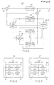
- Fig. 4 is a block diagram of a predictive encoder comprising a signal processing unit according to a first embodiment of this invention;
- Fig. 5 is a block diagram of an equivalent circuit of the predictive encoder shown in Fig. 4;
- Fig. 6 schematically shows a first control circuit used in the signal processing unit shown in Fig. 4;
- Fig. 7 likewise shows a second control circuit used in the signal processing unit shown in Fig. 4; and
- Fig. 8 is a block diagram of a predictive decoder comprising a signal processing unit according to a second embodiment of this invention.
- Referring to Fig. 1, attention will be directed to a
picture 10 which is being transmitted from a transmitting end of a conference television system. Thepicture 10 shows astationary area 12 and amovable object 14. In the illustrated example, the movable object is a person who is participating in a conference. Thestationary area 12 represents a background of themovable object 14. When themovable object 14 moves in a certain direction, such as a left direction indicated by anarrow 16, anew background 18 becomes visible as a part of thebackground 12 in the manner depicted right to themovable object 14. - Referring to Fig. 2, a conventional signal processing unit will be described for a better understanding of the present invention. The signal processing unit comprises a
quantizer 21, an inframe orintraframe prediction circuit 22, aninterframe prediction circuit 23, aselection circuit 24, asubtractor 26, and anadder 27 in the manner which will presently become clear. A succession of picture data is supplied to thesubtractor 26 as an original signal through aninput terminal 28. A prediction signal is also supplied to thesubtractor 26 from theselection circuit 24. Thesubtractor 26 subtracts the prediction signal from the original signal. A result of subtraction is produced as a differential signal from thesubtractor 26. The differential signal is supplied to thequantizer 21. Thequantizer 21 is for quantizing the differential signal into a quantized signal. The quantized signal is transmitted as a succession of coded data from anoutput terminal 29. - The quantized and the prediction signals are supplied to the
adder 27 and are added together. A result of addition is produced as a local signal from theadder 27. It will be understood that the local signal is similar to the original signal and may therefore be referred to also as an original. The local signal is supplied to the inframe prediction, the interframe prediction, and theselection circuits interframe prediction circuits selection circuit 24. By way of example, the inframe and interframe prediction signals which appear at the current instant may be referred to as first and second prediction parts derived with reference to first and second parts appearing in the original signal at first and second instants which precede the current instant. Theselection circuit 24 is responsive to the local, the inframe prediction, and the interframe prediction signals for selecting one of the inframe and the interframe prediction signals to produce the prediction signal. - Referring to Fig. 3, a selection rule is used in the
selection circuit 24 in regard to picture elements Sx and Sa to Sd depicted at the top of the picture. The picture element Sx is for prediction at a current instant and is herein called a current picture element. Each of the other picture elements Sa to Sd is adjacent to the current picture element Sx and hence is herein called an adjacent picture element. - For the current picture element Sx, the adjacent picture elements Sa to Sd are already predictively selected by the
selection circuit 24. A result of selection of the adjacent picture elements Sa to Sd is represented by logic "1" or "0" in the figure with the current picture element shown by a cross. The logic "1" is representative of the result of selection by which the interframe prediction signal is selected by theselection circuit 24. The logic "0" is representative of the result of selection by which the inframe prediction signal is selected by theselection circuit 24. The result of selection is memorized in a memory part (not shown) of theselection circuit 24. - The current picture element Sx is calculated by a predetermined expression which will generally be given as follows:
Sx = f(Sa, Sb, Sc, Sd).
That is, the logic "1" or "0" of the present picture element Sx is decided by a result of the expression in the manner depicted in the figure by Sx = 0 or Sx = 1. It should be understood also as regards the current picture element Sx that the logic "1" and "0" are representative of the interframe prediction and the inframe prediction signals, respectively. - Referring to Figs. 4 and 5, a predictive encoder comprises a signal processing unit according to a first embodiment of this invention. The signal processing unit comprises similar parts designated by like reference numerals. In the manner which will be described in the following, the signal processing unit further comprises a
background prediction circuit 31, a motionvector detection circuit 33, and acode converter 34. Theselection circuit 24 comprises a first selectingpart 36, a second selectingpart 37, afirst control circuit 38, and asecond control circuit 39. - The
inframe prediction circuit 22 includes aline memory 41. Theline memory 41 is capable of temporarily memorizing the local signal for producing the inframe prediction signal. For theline memory 41, a first delay time is determined for delaying the local signal. The first delay time corresponds to a single line which comprises a plurality of picture elements. Alternatively, the first delay time may be a time interval between two adjacent picture elements. From theline memory 41, the local signal is delivered as the inframe prediction signal to thesecond control circuit 39 and the second selectingpart 37. - The
interframe prediction circuit 23 includes aframe memory 43 and adelay adjusting circuit 44. Theframe memory 43 is capable of memorizing the local signal. In theframe memory 43, a second delay time is determined for delaying the local signal. The second delay time corresponds to a single frame which comprises a plurality of lines. The local signal is sent from theframe memory 43 to thedelay adjusting circuit 44. In thedelay adjusting circuit 44, the second delay time is adjusted in response to a motion vector signal sent from the motionvector detection circuit 33 in the manner which will presently be described. Namely, the interframe prediction signal is motion-compensated. Such motion compensating operation is disclosed in United States patent No. 4,307,420 issued to Yuichi Ninomiya et al and assigned to Nippon Hoso Kyokai, a public television broadcasting association in Japan. From thedelay adjusting circuit 44, the local signal is delivered as the interframe prediction signal to thefirst control circuit 38 and the first selectingpart 36. - The
background prediction circuit 31 comprises alocal subtractor 51, a local comparingcircuit 52, alocal adder 53, adelay circuit 54, and abackground memory 55. Thelocal subtractor 51 subtracts that preceding background signal from the local signal which is sent from thebackground memory 55 through aline 56. A result of the subtraction is produced as a local differential signal from thelocal subtractor 51. The local differential signal is supplied to the local comparingcircuit 52. An absolute value of the local differential signal is compared with a predetermined threshold value in the local comparingcircuit 52. When the absolute value of the local differential signal is lower than the predetermined threshold value, zero is sent to thelocal adder 53 as a predetermined value. Otherwise, the local differential signal is supplied as a modified differential signal to thelocal adder 53. - The
local adder 53 adds the modified differential signal to the preceding background signal which is supplied from thedelay circuit 55 through aline 57. A result of the addition is produced as a background prediction signal from thelocal adder 53 and is supplied to the first selectingpart 36, thefirst control circuit 38, and thebackground memory 55. For convenience of description, the background prediction signal which appears at the current instant will be referred to as a third prediction part produced with reference to a third part appearing in the original signal at a third instant which precedes the current instant and which is different from the first and second instants. - The
background memory 55 is capable of memorizing the single frame of the background prediction signal. In thebackground memory 55, a third delay time is determined for delaying the background predictive signal. The third delay time corresponds to the single frame. - The background prediction signal is supplied as the preceding background signal from the
background memory 55 to thelocal subtractor 51 and thedelay circuit 54. Thedelay circuit 54 is for delaying the background prediction signal in response to the local comparingcircuit 52. - Operation of the local comparing
circuit 52 may be controlled ry the motion vector signal derived from the motionvector detection circuit 33. More particularly, the local comparingcircuit 52 may be designed so as to produce the predetermined value of zero on noting of the motion vector signal irrespective of production or not of the local differential signal. - Referring to Fig. 6 in addition to Fig. 4, the
first control circuit 38 comprises afirst calculation part 61, a first comparingpart 62, afirst memory part 63, and afirst judgment part 64. Thefirst calculation part 61 is responsive to the local, the interframe prediction, and the background prediction signals and is for .subtracting the local signal from each of the interframe and the background prediction signals to pr duce a first and a second prediction error signal. Absolute value of the first and the second prediction error signals are compared with each other in the first comparingpart 62. A smaller one of the first and the second prediction error signals is selected by the first comparingpart 62 and is memorized in thefirst memory part 63. A first judgment is carried out in thefirst judgment part 64 by using the first and the second prediction error signals which are memorized in thefirst memory part 63. The first judgment is for selecting a preferable one of the interframe and the background prediction signals to produce a selected prediction and a first selection or control signal. A rule for the first judgment may be similar to the selection rule described with reference to Fig. 3. The selected prediction signal is supplied to thesecond control circuit 39. - On the other hand, the first selection signal is sent to the first selecting
part 36. The first selectingpart 36 is responsive to the first selection signal and is for selecting one of the interframe and the background prediction signals to produce a local prediction signal which is equal to the selected prediction signal. The local prediction signal is supplied to the second selectingpart 37. The local prediction signal may also be supplied to thesecond control circuit 39 in spite of the selected prediction signal which is supplied through aline 66. - Referring to Fig. 7 in addition to Fig. 4, the
second control circuit 39 comprises asecond calculation part 71, a second comparingpart 72, asecond memory part 73, and asecond judgment part 74. Thesecond calculation part 71 is responsive to the local, the inframe prediction, and the local prediction signals and is for subtracting the local signal from each of the inframe and the local prediction signals to produce a third and a fourth prediction error signal. Absolute value of the third and the fourth prediction error signals are compared with each other in the second comparingpart 72. A smaller one of the third and the fourth prediction error signals is selected by the second comparingpart 72 and is memorized in thesecond memory part 73. A second judgment is carried out in thesecond judgment part 74 by using the third and the fourth prediction error signals which are memorized in thesecond memory part 73. The second judgment is for selecting a preferable one of the inframe and the local prediction signals to produce a second selection or control signal. A rule for the second judgment may also be similar to the selection rule described with reference to Fig. 3. - The second selection signal is sent to the second selecting
part 37. The second selectingpart 36 is responsive to the second selection signal and is for selecting one of the inframe and the local prediction signals to produce the prediction signal. - As will be clearly understood in the above description, a combination of the first and the
second control circuits - It will now be understood that the prediction signal is supplied to the
subtractor 26 and theadder 27 in the manner described with reference to Fig. 2. The quantized and the motion vector signals are supplied to thecode converter 34. Thecode converter 34 is for processing the quantized and the motion vector signals to produce an output signal of, for example, a Huffman code. The output signal is transmitted as a succession of coded data from theoutput terminal 29. - Referring to Fig. 8, a predictive decoder comprises a signal processing unit according to a second embodiment of this invention. The signal processing unit comprises similar parts designated by like reference numerals. In the manner which will be described in the following, the signal processing unit further comprises a
code converter 81 and anadder 82. - A succession of picture data is supplied to the
code converter 81 through theinput terminal 28 as an input signal. The picture data succession may be the coded data succession which is transmitted from the predictive encoder illustrated in Fig. 4. Thecode converter 81 is for processing the input signal to produce the motion vector signal and a converted local signal which is similar to the quantized signal described before. The motion vector signal is supplied to thedelay adjusting circuit 44 for adjusting the second delay time of theframe memory 43. - The converted local signal is supplied to the
adder 82. The prediction signal is also supplied to theadder 82 from the second selectingpart 37. Theadder 82 adds the converted local signal to the prediction signal. A result of addition is produced from theadder 82 as a decoded signal which is similar to the above- described original signal and may therefore be referred to also as an original. The decoded signal is supplied to the inframe prediction, the interframe prediction, the background prediction, the first control, and thesecond control circuits output terminal 29. - While this invention has thus far been described in conjunction with a few embodiment thereof, it will readily be possible for those skilled in the art to put this invention into practice in various other manners. It will be understood that various selection rule can be used for producing the prediction signal. For example, the selection rules used in the
selection circuit 24 may be combined together so as to estimate efficiency about the inframe, the interframe, and the background predictions and to give grades from a high efficiency. Under the circumstances, one of the predictions may be determined one time by comparing the grades of the picture elements which are already predicted and adjacent to a current picture element.
Claims (7)
Applications Claiming Priority (2)
| Application Number | Priority Date | Filing Date | Title |
|---|---|---|---|
| JP236227/84 | 1984-11-09 | ||
| JP59236227A JPS61114677A (en) | 1984-11-09 | 1984-11-09 | Adaptability prediction coding decoding system and device for animation signal |
Publications (3)
| Publication Number | Publication Date |
|---|---|
| EP0181237A2 true EP0181237A2 (en) | 1986-05-14 |
| EP0181237A3 EP0181237A3 (en) | 1987-07-15 |
| EP0181237B1 EP0181237B1 (en) | 1991-01-23 |
Family
ID=16997671
Family Applications (1)
| Application Number | Title | Priority Date | Filing Date |
|---|---|---|---|
| EP85308187A Expired - Lifetime EP0181237B1 (en) | 1984-11-09 | 1985-11-11 | Processing unit for digital picture signals with adaptive prediction |
Country Status (6)
| Country | Link |
|---|---|
| US (1) | US4802006A (en) |
| EP (1) | EP0181237B1 (en) |
| JP (1) | JPS61114677A (en) |
| AU (1) | AU579681B2 (en) |
| CA (1) | CA1238408A (en) |
| DE (1) | DE3581489D1 (en) |
Cited By (4)
| Publication number | Priority date | Publication date | Assignee | Title |
|---|---|---|---|---|
| EP0237989A1 (en) * | 1986-03-14 | 1987-09-23 | Fujitsu Limited | Differential coding apparatus having an optimum predicted value determining circuit |
| US5519436A (en) * | 1994-06-21 | 1996-05-21 | Intel Corporation | Static image background reference for video teleconferencing applications |
| US5608450A (en) * | 1994-09-07 | 1997-03-04 | Intel Corporation | Video conferencing system with fast packet loss recovery |
| US5781198A (en) * | 1995-12-22 | 1998-07-14 | Intel Corporation | Method and apparatus for replacing a background portion of an image |
Families Citing this family (26)
| Publication number | Priority date | Publication date | Assignee | Title |
|---|---|---|---|---|
| JPS61114676A (en) * | 1984-11-09 | 1986-06-02 | Nec Corp | Block coding device |
| JPS61118085A (en) * | 1984-11-14 | 1986-06-05 | Nec Corp | Coding system and device for picture signal |
| AU579441B2 (en) * | 1985-01-16 | 1988-11-24 | Mitsubishi Denki Kabushiki Kaisha | Video encoding apparatus |
| US4779131A (en) * | 1985-07-26 | 1988-10-18 | Sony Corporation | Apparatus for detecting television image movement |
| NL8700565A (en) * | 1987-03-10 | 1988-10-03 | Philips Nv | TV SYSTEM IN WHICH TRANSFORMED CODING TRANSFERS DIGITIZED IMAGES FROM A CODING STATION TO A DECODING STATION. |
| JP2801911B2 (en) * | 1987-10-16 | 1998-09-21 | 日本電気ホームエレクトロニクス 株式会社 | Apparatus for compressing image data by predictive coding |
| DE3811535A1 (en) * | 1988-04-06 | 1989-10-19 | Philips Patentverwaltung | HYBRID CODERS FOR VIDEO SIGNALS |
| US4953023A (en) * | 1988-09-29 | 1990-08-28 | Sony Corporation | Coding apparatus for encoding and compressing video data |
| US4891699A (en) * | 1989-02-23 | 1990-01-02 | Matsushita Electric Industrial Co., Ltd. | Receiving system for band-compression image signal |
| JP3159309B2 (en) * | 1989-09-27 | 2001-04-23 | ソニー株式会社 | Video signal encoding method and video signal encoding device |
| NL8902612A (en) * | 1989-10-23 | 1991-05-16 | Philips Nv | METHOD FOR TRANSMITTING A DIGITAL VIDEO SIGNAL AND RECEIVER FOR USE IN THE METHOD |
| US5150432A (en) * | 1990-03-26 | 1992-09-22 | Kabushiki Kaisha Toshiba | Apparatus for encoding/decoding video signals to improve quality of a specific region |
| US5091782A (en) * | 1990-04-09 | 1992-02-25 | General Instrument Corporation | Apparatus and method for adaptively compressing successive blocks of digital video |
| JPH05508754A (en) * | 1990-05-11 | 1993-12-02 | ピクチャテル コーポレイション | Hierarchical coding method and apparatus employing background reference for efficient transmission of image sequences |
| US5155594A (en) * | 1990-05-11 | 1992-10-13 | Picturetel Corporation | Hierarchical encoding method and apparatus employing background references for efficiently communicating image sequences |
| US5260783A (en) * | 1991-02-21 | 1993-11-09 | Gte Laboratories Incorporated | Layered DCT video coder for packet switched ATM networks |
| US5235419A (en) * | 1991-10-24 | 1993-08-10 | General Instrument Corporation | Adaptive motion compensation using a plurality of motion compensators |
| US5387938A (en) * | 1992-10-08 | 1995-02-07 | Matsushita Electric Industrial Co., Ltd. | Adaptive interframe/intraframe block coding method and apparatus |
| US5398079A (en) * | 1993-01-27 | 1995-03-14 | General Instrument Corporation | Half-pixel interpolation for a motion compensated digital video system |
| US5376968A (en) | 1993-03-11 | 1994-12-27 | General Instrument Corporation | Adaptive compression of digital video data using different modes such as PCM and DPCM |
| JPH0730888A (en) * | 1993-06-24 | 1995-01-31 | Canon Inc | Moving image transmitter and moving image receiver |
| KR0128859B1 (en) * | 1993-08-20 | 1998-04-10 | 배순훈 | Adaptive image coding controller |
| JPH07170521A (en) * | 1993-12-15 | 1995-07-04 | Canon Inc | Picture processor |
| US5486863A (en) * | 1994-04-29 | 1996-01-23 | Motorola, Inc. | Method for determining whether to intra code a video block |
| JP2933132B2 (en) * | 1997-01-09 | 1999-08-09 | 日本電気株式会社 | Multipoint video conference control device and screen synthesis encoding method |
| US8259801B2 (en) * | 2008-10-12 | 2012-09-04 | Mediatek Inc. | Methods for coding digital media data with prediction information and prediction error information being respectively carried by different bit stream sections |
Citations (5)
| Publication number | Priority date | Publication date | Assignee | Title |
|---|---|---|---|---|
| US3632865A (en) * | 1969-12-23 | 1972-01-04 | Bell Telephone Labor Inc | Predictive video encoding using measured subject velocity |
| US4133006A (en) * | 1976-10-22 | 1979-01-02 | Nippon Electric Co., Ltd. | Predictive encoder or decoder with selection of one of two or more prediction signals according to prediction error signal amplitudes |
| US4144543A (en) * | 1976-12-16 | 1979-03-13 | Nippon Electric Co., Ltd. | Predictive codec capable of selecting one of at least three prediction signals in two steps |
| US4217609A (en) * | 1978-02-28 | 1980-08-12 | Kokusai Denshin Denwa Kabushiki Kaisha | Adaptive predictive coding system for television signals |
| DE3222648A1 (en) * | 1981-06-19 | 1983-02-03 | Kokusai Denshin Denwa K.K., Tokyo | ADAPTABLE INTER-FRAME PREDICTION DEVICE FOR TELEVISION SIGNALS |
Family Cites Families (6)
| Publication number | Priority date | Publication date | Assignee | Title |
|---|---|---|---|---|
| JPS58127488A (en) * | 1982-01-25 | 1983-07-29 | Kokusai Denshin Denwa Co Ltd <Kdd> | Adaptation predicting coding system of television signal |
| AU2021383A (en) * | 1982-10-09 | 1984-04-12 | International Standard Electric Corp. | Digital p.c.m. communication system |
| AU570439B2 (en) * | 1983-03-28 | 1988-03-17 | Compression Labs, Inc. | A combined intraframe and interframe transform coding system |
| DE3311911A1 (en) * | 1983-03-31 | 1984-10-04 | Siemens AG, 1000 Berlin und 8000 München | METHOD AND CIRCUIT ARRANGEMENT FOR IMAGE ERROR CORRECTION |
| JPS59185487A (en) * | 1983-04-05 | 1984-10-22 | Nec Corp | Adaptive forecasting encoding and decoding system and device of multilevel picture signal |
| EP0123616B1 (en) * | 1983-04-20 | 1987-03-04 | Nippon Telegraph And Telephone Corporation | Interframe coding method and apparatus therefor |
-
1984
- 1984-11-09 JP JP59236227A patent/JPS61114677A/en active Pending
-
1985
- 1985-11-08 CA CA000494909A patent/CA1238408A/en not_active Expired
- 1985-11-11 DE DE8585308187T patent/DE3581489D1/en not_active Expired - Lifetime
- 1985-11-11 AU AU49743/85A patent/AU579681B2/en not_active Expired
- 1985-11-11 EP EP85308187A patent/EP0181237B1/en not_active Expired - Lifetime
- 1985-11-12 US US06/796,682 patent/US4802006A/en not_active Expired - Lifetime
Patent Citations (6)
| Publication number | Priority date | Publication date | Assignee | Title |
|---|---|---|---|---|
| US3632865A (en) * | 1969-12-23 | 1972-01-04 | Bell Telephone Labor Inc | Predictive video encoding using measured subject velocity |
| US4133006A (en) * | 1976-10-22 | 1979-01-02 | Nippon Electric Co., Ltd. | Predictive encoder or decoder with selection of one of two or more prediction signals according to prediction error signal amplitudes |
| US4144543A (en) * | 1976-12-16 | 1979-03-13 | Nippon Electric Co., Ltd. | Predictive codec capable of selecting one of at least three prediction signals in two steps |
| US4217609A (en) * | 1978-02-28 | 1980-08-12 | Kokusai Denshin Denwa Kabushiki Kaisha | Adaptive predictive coding system for television signals |
| DE3222648A1 (en) * | 1981-06-19 | 1983-02-03 | Kokusai Denshin Denwa K.K., Tokyo | ADAPTABLE INTER-FRAME PREDICTION DEVICE FOR TELEVISION SIGNALS |
| US4437119A (en) * | 1981-06-19 | 1984-03-13 | Kokusai Denshin Denwa Kabushiki Kaisha | Inter-frame adaptive prediction system for television signals |
Non-Patent Citations (2)
| Title |
|---|
| AN ADAPTIVE INTRAFRAME DPCM CODEC BASED UPON NONSTATIONARY IMAGE MODEL by N.F. MAXEMCHUK and J.A. STULLER, vol. 58, no. 6, July-August 1979 THE BELL SYSTEM TECHNICAL JOURNAL pages 1395-1412 * |
| ENTWURF EINES BLOCKWEISE ADAPTIVEN DPCM-CODERS FUR DIE M-SPEKTRAL-WERTE VON BILDDATEN by The-Anh Yuong, frequency 38 (1984) 10 pages 247-254 * |
Cited By (5)
| Publication number | Priority date | Publication date | Assignee | Title |
|---|---|---|---|---|
| EP0237989A1 (en) * | 1986-03-14 | 1987-09-23 | Fujitsu Limited | Differential coding apparatus having an optimum predicted value determining circuit |
| US4743967A (en) * | 1986-03-14 | 1988-05-10 | Fujitsu Limited | Differential coding apparatus having an optimum predicted value determining circuit |
| US5519436A (en) * | 1994-06-21 | 1996-05-21 | Intel Corporation | Static image background reference for video teleconferencing applications |
| US5608450A (en) * | 1994-09-07 | 1997-03-04 | Intel Corporation | Video conferencing system with fast packet loss recovery |
| US5781198A (en) * | 1995-12-22 | 1998-07-14 | Intel Corporation | Method and apparatus for replacing a background portion of an image |
Also Published As
| Publication number | Publication date |
|---|---|
| JPS61114677A (en) | 1986-06-02 |
| US4802006A (en) | 1989-01-31 |
| AU4974385A (en) | 1986-05-15 |
| DE3581489D1 (en) | 1991-02-28 |
| EP0181237B1 (en) | 1991-01-23 |
| AU579681B2 (en) | 1988-12-01 |
| CA1238408A (en) | 1988-06-21 |
| EP0181237A3 (en) | 1987-07-15 |
Similar Documents
| Publication | Publication Date | Title |
|---|---|---|
| EP0181237A2 (en) | Processing unit for digital picture signals with adaptive prediction | |
| EP0267581B1 (en) | Moving image signal coding system | |
| US5173773A (en) | Moving picture signal progressive coding system | |
| US4179710A (en) | Predictive encoder with a non-linear quantizing characteristic | |
| US4575756A (en) | Decoder for a frame or field skipped TV signal with a representative movement vector used for individual vectors | |
| US4689671A (en) | Coding apparatus for moving object image | |
| US4077053A (en) | Television signal encoder utilizing a correlation between frames | |
| US4133006A (en) | Predictive encoder or decoder with selection of one of two or more prediction signals according to prediction error signal amplitudes | |
| KR0129503B1 (en) | An encoder for coding a digital signal and an decoder for decoding a coded digital-signal | |
| US4733298A (en) | Method of coding a video signal whereby pictures can be reproduced with a high quality and a device therefor | |
| EP0589504B1 (en) | System comprising at least one encoder for coding a digital signal and at least one decoder for decoding a digital signal | |
| CA1266912A (en) | Method and apparatus for coding motion image signal | |
| US5432555A (en) | Image signal encoding apparatus using adaptive 1D/2D DCT compression technique | |
| US5418617A (en) | Motion compensation using minimum bits per motion block as criterion for block matching | |
| EP0588410B1 (en) | System comprising a first encoder for coding a first digital signal and a second encoder for coding a second digital signal (e.g. stereoscopic video signal) | |
| US4684984A (en) | Motion compensated interframe decoding apparatus | |
| EP0639924B1 (en) | Coding mode control device for digital video signal coding system | |
| JPS61283294A (en) | Compensating and encoding system for motion and its device | |
| JPH0273793A (en) | High efficient coding device | |
| JPH05227513A (en) | Video signal transmitter | |
| JPS5814688A (en) | Intra-frame estimation coding device | |
| JP2509164B2 (en) | Video signal coding method | |
| JPS61173593A (en) | Predictive encoding system | |
| JPS6127950B2 (en) | ||
| JPS61201568A (en) | Adaptive coding system |
Legal Events
| Date | Code | Title | Description |
|---|---|---|---|
| PUAI | Public reference made under article 153(3) epc to a published international application that has entered the european phase |
Free format text: ORIGINAL CODE: 0009012 |
|
| 17P | Request for examination filed |
Effective date: 19851122 |
|
| AK | Designated contracting states |
Kind code of ref document: A2 Designated state(s): DE FR GB IT |
|
| PUAL | Search report despatched |
Free format text: ORIGINAL CODE: 0009013 |
|
| AK | Designated contracting states |
Kind code of ref document: A3 Designated state(s): DE FR GB IT |
|
| 17Q | First examination report despatched |
Effective date: 19890714 |
|
| GRAA | (expected) grant |
Free format text: ORIGINAL CODE: 0009210 |
|
| AK | Designated contracting states |
Kind code of ref document: B1 Designated state(s): DE FR GB IT |
|
| REF | Corresponds to: |
Ref document number: 3581489 Country of ref document: DE Date of ref document: 19910228 |
|
| ET | Fr: translation filed | ||
| ITF | It: translation for a ep patent filed |
Owner name: MODIANO & ASSOCIATI S.R.L. |
|
| PLBE | No opposition filed within time limit |
Free format text: ORIGINAL CODE: 0009261 |
|
| STAA | Information on the status of an ep patent application or granted ep patent |
Free format text: STATUS: NO OPPOSITION FILED WITHIN TIME LIMIT |
|
| 26N | No opposition filed | ||
| REG | Reference to a national code |
Ref country code: GB Ref legal event code: IF02 |
|
| PGFP | Annual fee paid to national office [announced via postgrant information from national office to epo] |
Ref country code: DE Payment date: 20041104 Year of fee payment: 20 |
|
| PGFP | Annual fee paid to national office [announced via postgrant information from national office to epo] |
Ref country code: FR Payment date: 20041109 Year of fee payment: 20 |
|
| PGFP | Annual fee paid to national office [announced via postgrant information from national office to epo] |
Ref country code: GB Payment date: 20041110 Year of fee payment: 20 |
|
| PG25 | Lapsed in a contracting state [announced via postgrant information from national office to epo] |
Ref country code: GB Free format text: LAPSE BECAUSE OF EXPIRATION OF PROTECTION Effective date: 20051110 |
|
| REG | Reference to a national code |
Ref country code: GB Ref legal event code: PE20 |