EP0180401A2 - Document inserter systems - Google Patents
Document inserter systems Download PDFInfo
- Publication number
- EP0180401A2 EP0180401A2 EP85307633A EP85307633A EP0180401A2 EP 0180401 A2 EP0180401 A2 EP 0180401A2 EP 85307633 A EP85307633 A EP 85307633A EP 85307633 A EP85307633 A EP 85307633A EP 0180401 A2 EP0180401 A2 EP 0180401A2
- Authority
- EP
- European Patent Office
- Prior art keywords
- control
- web
- forms
- information
- control information
- Prior art date
- Legal status (The legal status is an assumption and is not a legal conclusion. Google has not performed a legal analysis and makes no representation as to the accuracy of the status listed.)
- Granted
Links
Images


Classifications
-
- B—PERFORMING OPERATIONS; TRANSPORTING
- B07—SEPARATING SOLIDS FROM SOLIDS; SORTING
- B07C—POSTAL SORTING; SORTING INDIVIDUAL ARTICLES, OR BULK MATERIAL FIT TO BE SORTED PIECE-MEAL, e.g. BY PICKING
- B07C1/00—Measures preceding sorting according to destination
-
- G—PHYSICS
- G05—CONTROLLING; REGULATING
- G05B—CONTROL OR REGULATING SYSTEMS IN GENERAL; FUNCTIONAL ELEMENTS OF SUCH SYSTEMS; MONITORING OR TESTING ARRANGEMENTS FOR SUCH SYSTEMS OR ELEMENTS
- G05B2219/00—Program-control systems
- G05B2219/20—Pc systems
- G05B2219/24—Pc safety
- G05B2219/24117—If error detected, shut down
-
- G—PHYSICS
- G05—CONTROLLING; REGULATING
- G05B—CONTROL OR REGULATING SYSTEMS IN GENERAL; FUNCTIONAL ELEMENTS OF SUCH SYSTEMS; MONITORING OR TESTING ARRANGEMENTS FOR SUCH SYSTEMS OR ELEMENTS
- G05B2219/00—Program-control systems
- G05B2219/20—Pc systems
- G05B2219/25—Pc structure of the system
- G05B2219/25339—Supervisory plus control computer
-
- G—PHYSICS
- G05—CONTROLLING; REGULATING
- G05B—CONTROL OR REGULATING SYSTEMS IN GENERAL; FUNCTIONAL ELEMENTS OF SUCH SYSTEMS; MONITORING OR TESTING ARRANGEMENTS FOR SUCH SYSTEMS OR ELEMENTS
- G05B2219/00—Program-control systems
- G05B2219/20—Pc systems
- G05B2219/25—Pc structure of the system
- G05B2219/25391—Start, stop sequence of different parts of machine, copier, textile, glass
-
- Y—GENERAL TAGGING OF NEW TECHNOLOGICAL DEVELOPMENTS; GENERAL TAGGING OF CROSS-SECTIONAL TECHNOLOGIES SPANNING OVER SEVERAL SECTIONS OF THE IPC; TECHNICAL SUBJECTS COVERED BY FORMER USPC CROSS-REFERENCE ART COLLECTIONS [XRACs] AND DIGESTS
- Y10—TECHNICAL SUBJECTS COVERED BY FORMER USPC
- Y10S—TECHNICAL SUBJECTS COVERED BY FORMER USPC CROSS-REFERENCE ART COLLECTIONS [XRACs] AND DIGESTS
- Y10S345/00—Computer graphics processing and selective visual display systems
- Y10S345/902—Menu display
Definitions
- This invention relates to inserter systems which assemble batches of documents, which may be sheets and/or forms, for insertion into envelopes. More particularly it relates to control systems for such inserter systems.
- sheets herein is meant single sheet documents and by forms herein is meant documents which comprise a web and which are separated from such web by such inserter systems).
- Such systems are known in the art and are generally used by organizations which make large mailings where the contents of each item mailed may vary.
- Such systems typically comprise: feeder modules for insertion of sheets into a batch, either multiply or singly; web modules for separating webs into discrete forms and inserting the discrete forms into the batch; envelope modules for inserting the batches into envelopes; a transport system for conveying sheets and forms through the various modules to form proper batches; inserter modules for inserting the batches into envelopes, which are preferably preaddressed; optionally, meter modules for metering the envelopes with appropriate postage; and a control system to synchronize the operation of the inserter system to assure that the batches are properly assembled, inserted into envelopes, and, possibly, metered.
- Information for control of such known inserters system is read from a control document, which is preferably a form, by a scanner associated with the feeder module or web module which feeds that document.
- a scanner associated with the feeder module or web module which feeds that document.
- that module is the most upstream module along the transport system.
- the scanner reads information from the control document which typically includes information such as information defining the number of documents to be inserted at each module, information providing an I.D. code for comparison with I.D, codes on inserted documents to assure that documents are properly matched, and, possibly, information for other purposes such as selection of postage.
- This control information is then transmitted to the control system which controls the operation of the inserter system accordingly to assure the proper assembly and processing of each batch as defined by a control document.
- inserter systems generally comprise an upstream web module, or modules, which feed accumulations of forms (i.e., a control form and optionally, one or more succeeding non-control forms from the web) into a sheet inserter system; including feeder modules, inserter modules and, possibly, postage meter modules, where appropriate sheets would be inserted to complete the batch, the batch inserted into an envelope, and, possibly, postage indicia imprinted.
- forms i.e., a control form and optionally, one or more succeeding non-control forms from the web
- sheet inserter system including feeder modules, inserter modules and, possibly, postage meter modules, where appropriate sheets would be inserted to complete the batch, the batch inserted into an envelope, and, possibly, postage indicia imprinted.
- Such sheet inserter systems are known and typical examples are described in U.S.
- Web modules comprise a forms feeder which feeds a web of forms into a burster-folder, where the web is separated into discrete forms, which may be folded to fit into an envelope, if necessary, and a scanner which reads information from the web before bursting. To prevent accidental premature bursting a slack loop of web is maintained between the forms feeder and the burster-folder.
- the forms feeder removes the sprocket strips, which are used to drive the web, from the web. Accordingly, in systems where control information is printed on the sprocket strips (in order not to print exstraneous information on the form to be mailed) the scanner must be positioned to scan the web before the sprocket strips are removed.
- Web modules may also include an accumulator which accumulates a number of succeeding non-control forms with a control form and then feeds the accumulation into a batch.
- control information is imprinted on the sprocket strips of control forms included in a first web, and the control information is scanned and the sprocket strips removed from the web prior to separation of the web into discrete forms.
- a system comprising a first web module for receiving the first web, scanning the sprocket strips of the first web for control information, removing the sprocket strips, storing and retransmitting the control information, separating the web into discrete forms, forming accumulations of the discrete forms, and feeding said accumulations for further processing by the system.
- the system further includes a second web module for receiving a second web, separating the second web into second discrete forms, forming second accumulations of the second discrete forms, and feeding the second accumulations synchronously with the first accumulations for further processing by the system.
- the system is controlled by a supervisory control system which includes a non-volatile memory, which supervisory control system receives the retransmitted control information and controls the operation of the system.
- the supervisory control system is further responsive to a shut-down signal to complete operations in accordance with control information from control forms which have been separated from the first web, receive from the first web module the control information associated with unseparated control forms from which the sprocket strips have been removed, store this information in the non-volatile memory, and halt operation of the system.
- the supervisory control system is further responsive to a restart signal to read the stored information from the non-volatile memory and restart operations in accordance with the stored information to complete processing of the control documents from which the control information has been removed.
- FIG. 1 shows a schematic representation of an inserter system in accordance with the subject invention.
- the system of Figure 1 includes 4 web modules 20-1 through 20-4 which feed webs of computer print-out forms 10-1 through 10-4 into the system.
- Each web module 20 feeds a web 10, scans it for information, separates webs 10 into discrete forms and forms accumulations of discrete forms in accordance with the information scanned from a control form included in the most upstream web 10-1. These accumulations are then fed synchronously to transport unit 30. Selected accumulations from one or more of web modules 20 are gathered with the control document on transport unit 30 to form batches of forms for further processing.
- an example of this grouping of accumulations of forms into batches is shown at times t l through t 5 .
- control form possibly with an accumulation of non-control forms from web 10-1, is fed to transport unit 30 to begin grouping appropriate forms into a batch.
- transport unit 30 moves the batch to web module 20-2 where, in accordance with information scanned from the control document an accumulation of forms from web module 20-2 is grouped with the batch.
- the batch is moved to web module 20-3, where in accordance with the information scanned from the control document no accumulation of forms is added.
- an accumulation from web module 20-4 is added to the batch.
- the batch is fed to transfer unit 50 which transfers the batch to the transport unit 42 of sheet inserter module 40 where additional sheets may be added to the batch, the batch inserted in an envelope and appropriate postage imprinted on the envelope in accordance with the information scanned from the control document.
- Sheet inserter system 40 and transfer unit 50 may be conventional units known and well understood by those skilled in the art, such as the INSERTAMAX II or INSERTAMAX III systems, available from the Pitney Bowes Corporation of Stamford, Connecticut.
- sheet inserter system 40 may be a more sophisticated system such as that described in European Patent application No. 83-303757.5. The operation of such INSERTAMAX type transfer units and sheet inserter systems is well understood by those skilled in the art and need not be described further here for an understanding of this invention.
- web module 20-1 is typical of web modules used in embodiments of the subject invention. It comprises a forms feeder 22-1 which draws in web 10-1 by means of sprocket wheels engaged with sprocket strips fixed to the edges of web 10-1. Forms feeder 22-1 draws web 10-1 past scanner 24-l and separates the sprocket strips from web 10-1 before feeding it to burster-folder 26-1. Forms feeder 22-1 is controlled to maintain a slack loop of web between itself and burster-feeder 26-1 and to feed web 10-1 on a demand basis.
- Scanner 24-1 scans the forms in the web for machine readable information imprinted on the forms in the web. In module 20-1 this would include control information printed on control documents and, possibly, I.D. information printed on other, non-control, documents in web.10-1. In downstream modules 20-2 through 20-4 scanners 24-2 through 24-4 would scan for I.D. information.
- Scanner 24-1 is positioned to scan web 10-1 prior to the point where the sprocket strips are removed since in many embodiments of the subject invention information is printed on the sprocket strips rather than on the face of the forms themselves.
- Burster-folder 26-1 separates web 10-1 into discrete forms and accumulates these forms in accumulator 28-1.
- the control form, and possibly a number of succeeding non-control forms from web 10-1 are accumulated in accumulator 28-1 in accordance with control information on the control document.
- other accumulations of discrete forms which are to be added to the batch defined by the control document may be accumulated. These accumulations are fed to transport unit 30 in synchronism so as to properly form the batch defined by the control document. As described above, this batch is then fed to transfer unit 50 and sheet inserter system 40 for further processing in a conventional manner.
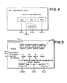
- FIG. 2 shows a block diagram of the control system for the inserter of Figure 1.
- the control system includes module control systems 20-lc through 20-4c, which control web modules 20-1 through 20-4 respectively, and supervisory control system 100.
- Module control systems 20-lc through 20-4c are substantially identical and module 20-lc is shown in Figure 1 as typical.
- Module control means 20-lc in turn comprises 3 microprocessors 22-lc, 24-lc and 26-lc, which may be Intel Model 8741 Microprocessors available from the Intel Corp. Santa Clara, CA, and which control form feeder 22-1, scanner 24-1 and burster-folder 26-1, respectively.
- Supervisory control system 100 comprises a single board computer, including processor 110, and which may be a Model SPC 20/4, also available from the above Intel Corp. Supervisory control system 100 also.includes random access memory (RAM) 130, which serves as the program memory for supervisory control system 100, and a non-volatile memory, which in the embodiment of Figure 2 comprises a floppy disk drive 142 and floppy disk controller 140, which is used to initially load the operating program during start-up, as well as other information as will be described further below. Supervisory control system 100 also includes an operator interface 120 which is used by an operator to input the configuration for a mailing. Preferably, interface 120 comprises a touch screen, such as an INFOTOUCH model touch screen sold by Fluke Manufacturing Co., Seattle, WA, but may also be any of a number of other well known conventional operator interfaces.
- a touch screen such as an INFOTOUCH model touch screen sold by Fluke Manufacturing Co., Seattle, WA, but may also be any of a number of other well known conventional operator interfaces.
- transport unit 30 operates under the direct control of supervisory control system 100 through a conventional interface/controller 30-c which is connected to an I/O channel of processor 110.
- Encoder 32 provides position information to processor 110 for control of transport unit 30.
- Supervisory control system 100 also communicates with sheet inserter system 40 through inserter interface 40-c, which is also directly connected to an I/O channel of processor 110.
- sheet inserter system 40 operates, in the embodiment illustrated, under its own control system. Accordingly, supervisory control system 100 communicates to inserter 40 parameters which define the operations to be carried out on a batch by sheet inserter system 40 in accordance with information scanned from the control document.
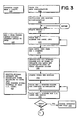
- FIG 3 shows a simplified flow chart of the operation of the inserter system of the subject invention.
- the operator loads webs 10-1 through 10-4 into web modules 20-1 through 20-4, initially aligning each web so that its start position is known.
- the operator also loads appropriate sheets into the feeder stations of sheet inserter system 40 in accordance with the instructions for a particular mailing.
- the operator inputs information defining the configuration for that mailing through operator interface 120 in a manner which will be described more fully below.
- This configuration information defines various parameters for the forms of webs 10-1 through 10-4 to be used with a particular mailing. Typically, such information would include form length, position of control and I.D.
- the configuration may also include information such as which web module will feed the web containing the control forms, and the number of documents to be maintained in the loop between the forms feeder and the burster-folder.
- forms feeder control 22-lc is initialized with information defining the length of forms and the position of information on the forms, while scanner control system 24-lc is initialized with information for interpreting the codes on the forms of web 10-1.
- Other module control systems 20-2c through 20-4c will be initialized in a similar manner except that scanner 24-1 will scan for both control information and I.D. codes while the other scanners will scan only for I.D. codes.
- supervisory control system 100 starts web module 1.
- Forms feeder control 22-lc controls forms feeder 22-1 to advance web 10-1 to establish a loop and feed into burster-folder 26-1.
- feeder controller 22-lc monitors the positions of the forms and as information passes scanner 24-1 forms feeder control 22-lc signals scanner control 24-lc to start scanning, as shown at 211.
- supervisory control system 100 polls scanner controller 24-lc for control information.
- Scanner controller 24-lc interprets the information read from the forms in accordance with the information provided defining the configuration and responds to supervisory control system 100 when it has read control information from a control form.
- supervisory control system 100 responds to a signal from scanner controller 24-lc to exit its polling loop and read the control information from scanner controller 24-lc. This control information defines the particular batch associated with that particular control form.
- supervisory controller 100 controls burster-folder controller 26-lc to separate and accumulate in
- accumulator 28-1 a particular number of forms as defined by the control information for the batch associated with the particular control form. It also transmits to sheet inserter system 40 the information defining the number of sheets to be inserted at each feeder station of sheet inserter system 40, and, possibly, information defining the postage to be applied to that particular batch.
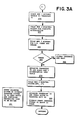
- supervisory control system 100 starts web modules 20-2 through 20-4.
- burster- folders separate and accumulate forms according to the control information into accumulators 28-2 through 28-4.
- Form feeder controllers 22-2c through 22-4c signal scanner controllers 24-2c through 24-4c to scan forms for I.D. codes.
- supervisory controller system 100 loops to poll burster-folder controller 26-lc to determine when the accumulation is complete.
- burster-folder controller 26-lc signals supervisory controller system 100 that the accumulation is complete system 100 exits the polling loop and polls scanner controller 24-lc for I.D. codes and checks the I.D. codes to assure that the accumulation has been formed properly.
- I.D. codes will consist of random 3 or 4 bit binary numbers imprinted on each document associated with a particular batch.
- the inserter system of the subject invention signals the operator and halts (or takes other appropriate action in response to the error).
- supervisory control system 100 loads the accumulation of discrete forms in accumulator 28-1 onto transport unit 30.
- supervisory control system 100 polls burster-folder controller 26-2c for a complete accumulation.
- burster-folder controller signals that the accumulation is complete in accumulator 28-2
- supervisory controller system 100 exits the polling loop and poles scanner controller 24-2c for I.D. codes at 260 and checks, after receiving the codes, to assure that the appropriate forms have been added to the batch.
- the system again signals the operator and halts at 266. If no error is detected, supervisory control system 100 advances transport unit 30 and loads the contents of accumulator 28-2 onto transport unit 30 adding them to the batch.
- supervisory control system 100 advances transport unit 30 and feeds the batch to transfer unit 50, at 280 supervisory control system 100 also signals sheet inserter system 40 that a batch is read and returns to begin processing another batch. At 281, sheet inserter system 40 signals transfer unit 50 to feed the batch and completes processing.
- Figures 4 through 9 show the displays on the touch screen of operator interface 120 used to establish configurations for a particular mailing.
- supervisory control system 100 When the inserter system of the subject invention is initially energized, supervisory control system 100 enters a conventional power-up routine and performs various checks to assure that the system is operational. If the system checks out properly, the image shown in Figure 4 is displayed on the touch screen of interface 120. By selecting one of the labeled areas shown, the operator may select a configuration for a particular mailing.
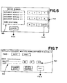
- the document number defining the particular document type to be run in each module is displayed.
- the kind of document, whether a form or sheet, is displayed.
- the number of documents currently in process in the web module is displayed.
- the document numbers displayed at 312 define document types in terms of predefined information stored on floppy disk 142. This information defines particular types of documents, identified by particular document numbers, in terms of document kind, length, position of machine readable information, whether or not the document may be a control document, and information needed to interpret machine readable information on the document. Thus, the specification of document numbers for each web module specifies a configuration in terms of the stored, predetermined information.
- web modules 20-1 through 20-4 may optionally be equipped with a sheet feeder option to allow them to handle both sheets and webs of forms.
- the operator may touch the area marked "OR” to display the image shown in Figure 7.
- This image provides more detailed information on each actual document in web modules 20-1 through 20-4; particularly at 322 the actual dash code on each document is shown.
- the operator may move among the various dashes of the dash codes displayed and selectively change them to change the effective dash code on a document. This would, for example, allow correction of an erroneously read dash code.
- the areas marked "NEXT” and "PREV” the operator may then move from document to document. When satisfied the operator may return to the image of Figure 5 by touching the area marked "EXIT". If the operator now touches the area marked "READY", the configuration displayed will be run, including any corrections entered through Figure 7.
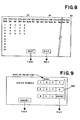
- Touching the area marked "OLD” on the touch screen causes the image shown in Figure 9 to be displayed. Entering the number of a previously established configuration through the numeric pad area 330 shown on the touch screen then touching the area marked "ENTER” returns the system to the image of Figure 5 which then displays the status of the entered old configuration. The operator may then proceed to start the system, change the set up, or exit, as described above.
- the operator may create new configurations by touching the area marked "NEW" on the touch screen of Figure 4.
- the system will then display the image shown in Figure 6.
- the operator may then enter a document number for each web module 20-1 through 20-4 of the above-described embodiment of the subject invention, entering zero for non-selected modules. After the document number for the last web module is entered, the system displays the image of Figure 5 and operations proceed as described above.
- the operator may cause the system to display the image of Figure 8 on the touch screen.
- This image shows a listing of all established configurations for the system.
- the operator may call up more configurations if the number of defined configurations exceeds the available space for display.
- the operator may return to the image of Figure 4.
- touch screens are well known commercially available devices and programming of supervisory control system 100 to control the touch of interface 120 in the above-described manner, is also a well known conventional technique well within the skill of those skilled in the art.
- supervisory control system 100 when supervisory control system 100 receives a shut-down signal it completes processing of control forms which have been separated from web 10-1 and their associated batches and polls scanner control 24-lc for the control information and I.D. numbers which have been read from the forms in the loops. Prior to shut-down then the information is stored on a disk in floppy disk drive 142. On start-up, this information is recalled from the disk and the inserter system may be restarted in this configuration by selecting the "LAST" option from the touch screen in the manner described above.
Abstract
Description
- This invention relates to inserter systems which assemble batches of documents, which may be sheets and/or forms, for insertion into envelopes. More particularly it relates to control systems for such inserter systems. (By sheets herein is meant single sheet documents and by forms herein is meant documents which comprise a web and which are separated from such web by such inserter systems).
- Such systems are known in the art and are generally used by organizations which make large mailings where the contents of each item mailed may vary. Such systems typically comprise: feeder modules for insertion of sheets into a batch, either multiply or singly; web modules for separating webs into discrete forms and inserting the discrete forms into the batch; envelope modules for inserting the batches into envelopes; a transport system for conveying sheets and forms through the various modules to form proper batches; inserter modules for inserting the batches into envelopes, which are preferably preaddressed; optionally, meter modules for metering the envelopes with appropriate postage; and a control system to synchronize the operation of the inserter system to assure that the batches are properly assembled, inserted into envelopes, and, possibly, metered.
- Information for control of such known inserters system is read from a control document, which is preferably a form, by a scanner associated with the feeder module or web module which feeds that document. Preferably that module is the most upstream module along the transport system. The scanner reads information from the control document which typically includes information such as information defining the number of documents to be inserted at each module, information providing an I.D. code for comparison with I.D, codes on inserted documents to assure that documents are properly matched, and, possibly, information for other purposes such as selection of postage. This control information is then transmitted to the control system which controls the operation of the inserter system accordingly to assure the proper assembly and processing of each batch as defined by a control document.
- As noted above control documents are preferably forms since compilation of the control information for each batch is most readily done through data processing with output through a line printer onto a web of computer printout forms. Accordingly, inserter systems generally comprise an upstream web module, or modules, which feed accumulations of forms (i.e., a control form and optionally, one or more succeeding non-control forms from the web) into a sheet inserter system; including feeder modules, inserter modules and, possibly, postage meter modules, where appropriate sheets would be inserted to complete the batch, the batch inserted into an envelope, and, possibly, postage indicia imprinted. Such sheet inserter systems are known and typical examples are described in U.S. Patent No.: 3,606,728; issued: September 21, 1971; to: Sather et al; assigned to Bell and Howell Co.; and U.S. Patent No.: 3 935 429; issued: January 27, 1976; to: Braneky et al; assigned to: Pitney Bowes Inc.
- Web modules comprise a forms feeder which feeds a web of forms into a burster-folder, where the web is separated into discrete forms, which may be folded to fit into an envelope, if necessary, and a scanner which reads information from the web before bursting. To prevent accidental premature bursting a slack loop of web is maintained between the forms feeder and the burster-folder.
- Typically, before the web is fed into the burster-folder the forms feeder removes the sprocket strips, which are used to drive the web, from the web. Accordingly, in systems where control information is printed on the sprocket strips (in order not to print exstraneous information on the form to be mailed) the scanner must be positioned to scan the web before the sprocket strips are removed.
- Web modules may also include an accumulator which accumulates a number of succeeding non-control forms with a control form and then feeds the accumulation into a batch.
- The mechanical construction and operation of web modules is well understood by those skilled in the art as is, as mentioned above, the control, construction and operation of conventional sheet inserter systems. U.S. Patent No.: 4,395,255, issued: July 26, 1983 to Braneky et al; assigned to Pitney Bowes Inc. teaches typical web handling equipment. Further discussion of sheet inserter systems and the mechanical aspects of web modules used in embodiments of the subject invention is not believed necessary for an understanding of the subject invention as described below and will not be discussed further herein.
- Such systems have in the past proved satisfactory for the automatic assembly of large mailings of varying items. They have, however, suffered from the disadvantage of an inflexible control structure, typically implemented with discrete hardwired logic, which was substantially limited in selection of configurations. (By configuration herein is meant parameters defining various aspects of a mailing which might include aspects such as form length, positioning of control information on the control document, the meaning of particular codes used to express the control information, the identity of the module which feeds the control document, and/or the number of forms needed in the slack loop.) Further, to the extent configurations could be changed such changes were complexed operations typically requiring the operator to make adjustments at various modules.
- Another problem was found in previously known inserter systems of the type wherein control information was printed on the sprocket strips. When an operator would halt the system in the middle of a mailing the system would complete operations on an item in process before halting. But frequently control forms with the sprocket strips, and the control information printed thereon, removed would be halted in the web loop. Thus, restarting the system to process these stripped control documents was a complex and difficult process.
- It would be desirable to have a system for the orderly shut down and restart of a multi-web inserter system of the type wherein control information is imprinted on the sprocket strips of control forms included in a first web, and the control information is scanned and the sprocket strips removed from the web prior to separation of the web into discrete forms.
- According to the invention, there is provided a system for orderly shut-down and restart of a multi-web inserter system of the type wherein control information is imprinted on the sprocket strips of control forms included in a first web, said control information is scanned and said sprocket strips removed from said web prior to separation of said web into discrete forms, comprising:
- a) first web module means for;
- receiving said first web;
- scanning said sprocket strips for said control information;
- removing said sprocket strips;
- storing and retransmitting said control information to supervisory control means for the control of said inserter means in accordance with said control information;
- separating said web into said discrete forms;
- forming accumulations of said forms;
- feeding said accumulations for further operations by said system;
- b) a second web module means for receiving a second web;
- separating said second web into second discrete forms;
- forming second accumulations of said second discrete forms;
- feeding said second accumulations synchronously with said first accumulations for further operations by said system;
- c) supervisory control means, including non-volatile memory means, for receiving said retransmitted control information and generating signals for control of said inserter system in accordance therewith;
- said supervisory control means being responsive to a shut-down signal to complete operations in accordance with said retransmitted control information associated with control forms which have been separated from said first web;
- receive from said first web module means said control information associated with unseparated control forms from which said sprocket strips have been removed;
- store said information associated with said unseparated control forms in said non-volatile memory;
- halt operation of said system; and,
- said supervisory control means being further responsive to a restart signal to read said stored information from said non-volatile memory and restart operations in accordance with said stored information.
- There is disclosed herein a system comprising a first web module for receiving the first web, scanning the sprocket strips of the first web for control information, removing the sprocket strips, storing and retransmitting the control information, separating the web into discrete forms, forming accumulations of the discrete forms, and feeding said accumulations for further processing by the system. The system further includes a second web module for receiving a second web, separating the second web into second discrete forms, forming second accumulations of the second discrete forms, and feeding the second accumulations synchronously with the first accumulations for further processing by the system. The system is controlled by a supervisory control system which includes a non-volatile memory, which supervisory control system receives the retransmitted control information and controls the operation of the system. The supervisory control system is further responsive to a shut-down signal to complete operations in accordance with control information from control forms which have been separated from the first web, receive from the first web module the control information associated with unseparated control forms from which the sprocket strips have been removed, store this information in the non-volatile memory, and halt operation of the system. The supervisory control system is further responsive to a restart signal to read the stored information from the non-volatile memory and restart operations in accordance with the stored information to complete processing of the control documents from which the control information has been removed.
- The invention will be better understood by those skilled in the art from the detailed description of a preferred embodiment set forth below and from consideration of the attached drawings in which:-
- Figure 1 shows a schematic representation of an inserter system including a multi-web inserter system and a sheet inserter system.
- Figure 2 shows a block diagram of the control system for the inserter system of Figure 1.
- Figures 3 and 3a show a simplified flow chart for the operation of the inserter system of Figure 1.
- Figures 4-9 show various menus displayed for selection of the initial configuration for a mailing.
- Figure 1 shows a schematic representation of an inserter system in accordance with the subject invention. The system of Figure 1 includes 4 web modules 20-1 through 20-4 which feed webs of computer print-out forms 10-1 through 10-4 into the system. Each
web module 20 feeds aweb 10, scans it for information, separateswebs 10 into discrete forms and forms accumulations of discrete forms in accordance with the information scanned from a control form included in the most upstream web 10-1. These accumulations are then fed synchronously to transportunit 30. Selected accumulations from one or more ofweb modules 20 are gathered with the control document ontransport unit 30 to form batches of forms for further processing. In Figure 1, an example of this grouping of accumulations of forms into batches is shown at times tl through t5. At tl the control form, possibly with an accumulation of non-control forms from web 10-1, is fed to transportunit 30 to begin grouping appropriate forms into a batch. At t2 transport unit 30 moves the batch to web module 20-2 where, in accordance with information scanned from the control document an accumulation of forms from web module 20-2 is grouped with the batch. At t3, the batch is moved to web module 20-3, where in accordance with the information scanned from the control document no accumulation of forms is added. Similarly, at t4 an accumulation from web module 20-4 is added to the batch. - At t5 the batch is fed to transfer
unit 50 which transfers the batch to thetransport unit 42 ofsheet inserter module 40 where additional sheets may be added to the batch, the batch inserted in an envelope and appropriate postage imprinted on the envelope in accordance with the information scanned from the control document. -
Sheet inserter system 40 andtransfer unit 50 may be conventional units known and well understood by those skilled in the art, such as the INSERTAMAX II or INSERTAMAX III systems, available from the Pitney Bowes Corporation of Stamford, Connecticut. Alternatively,sheet inserter system 40 may be a more sophisticated system such as that described in European Patent application No. 83-303757.5. The operation of such INSERTAMAX type transfer units and sheet inserter systems is well understood by those skilled in the art and need not be described further here for an understanding of this invention. - (Those skilled in the art will also recognize that the description of the subject invention has so far focused on a single batch as it moved through the system. However, they will also readily recognize that, given the high speed of electronic control systems in comparison to the mechanical operations of the inserter system, it would be a straight forward matter to concurrently control a number of batches
- moving sequentially through the system. However, though such concurrent control is in fact preferable, for the purpose of clarity the description of the subject invention herein will continue to focus on the sequence of operations on a single batch with the implicit understanding that other batches at other states of processing may proceed and follow that batch through the system.)
- Returning to Figure 1, web module 20-1 is typical of web modules used in embodiments of the subject invention. It comprises a forms feeder 22-1 which draws in web 10-1 by means of sprocket wheels engaged with sprocket strips fixed to the edges of web 10-1. Forms feeder 22-1 draws web 10-1 past scanner 24-l and separates the sprocket strips from web 10-1 before feeding it to burster-folder 26-1. Forms feeder 22-1 is controlled to maintain a slack loop of web between itself and burster-feeder 26-1 and to feed web 10-1 on a demand basis.
- Scanner 24-1 scans the forms in the web for machine readable information imprinted on the forms in the web. In module 20-1 this would include control information printed on control documents and, possibly, I.D. information printed on other, non-control, documents in web.10-1. In downstream modules 20-2 through 20-4 scanners 24-2 through 24-4 would scan for I.D. information. (Though those skilled in the art will recognize that inclusion of all control information on a single control document is preferable in terms of simplicity of operation, they will also recognize that additional control information may be included on documents fed by other modules and the response of the system modified in accordance with such additional control information.) Scanner 24-1 is positioned to scan web 10-1 prior to the point where the sprocket strips are removed since in many embodiments of the subject invention information is printed on the sprocket strips rather than on the face of the forms themselves.
- Burster-folder 26-1 separates web 10-1 into discrete forms and accumulates these forms in accumulator 28-1. In web module 20-1, the control form, and possibly a number of succeeding non-control forms from web 10-1, are accumulated in accumulator 28-1 in accordance with control information on the control document. In downstream web modules 20-2 through 20-4, other accumulations of discrete forms which are to be added to the batch defined by the control document may be accumulated. These accumulations are fed to transport
unit 30 in synchronism so as to properly form the batch defined by the control document. As described above, this batch is then fed to transferunit 50 andsheet inserter system 40 for further processing in a conventional manner. - The mechanical aspects of handling webs such as 10-1 separating them into discrete forms, accumulating the forms, transferring the accumulations to a transport unit such as
unit 30 and transporting the batches ontransport unit 30 to a sheet inserter system such as 40 are known and well understood by those skilled in the art. Accordingly, a further description of the mechanical aspects of the inserter system of the subject invention is not believed necessary to an understanding of the subject invention and will not be provided herein; except to note that it is believed preferable to operatetransport unit 30 asynchronously withtransport unit 42 and to feed batches to transferunit 50 andsheet inserter system 40 on a demand basis. - Figure 2 shows a block diagram of the control system for the inserter of Figure 1. The control system includes module control systems 20-lc through 20-4c, which control web modules 20-1 through 20-4 respectively, and
supervisory control system 100. Module control systems 20-lc through 20-4c are substantially identical and module 20-lc is shown in Figure 1 as typical. Module control means 20-lc in turn comprises 3 microprocessors 22-lc, 24-lc and 26-lc, which may be Intel Model 8741 Microprocessors available from the Intel Corp. Santa Clara, CA, and which control form feeder 22-1, scanner 24-1 and burster-folder 26-1, respectively. -
Supervisory control system 100 comprises a single board computer, includingprocessor 110, and which may be aModel SPC 20/4, also available from the above Intel Corp.Supervisory control system 100 also.includes random access memory (RAM) 130, which serves as the program memory forsupervisory control system 100, and a non-volatile memory, which in the embodiment of Figure 2 comprises afloppy disk drive 142 andfloppy disk controller 140, which is used to initially load the operating program during start-up, as well as other information as will be described further below.Supervisory control system 100 also includes anoperator interface 120 which is used by an operator to input the configuration for a mailing. Preferably,interface 120 comprises a touch screen, such as an INFOTOUCH model touch screen sold by Fluke Manufacturing Co., Seattle, WA, but may also be any of a number of other well known conventional operator interfaces. - In the embodiment shown,
transport unit 30 operates under the direct control ofsupervisory control system 100 through a conventional interface/controller 30-c which is connected to an I/O channel ofprocessor 110.Encoder 32 provides position information toprocessor 110 for control oftransport unit 30. -
Supervisory control system 100 also communicates withsheet inserter system 40 through inserter interface 40-c, which is also directly connected to an I/O channel ofprocessor 110. As noted above,sheet inserter system 40 operates, in the embodiment illustrated, under its own control system. Accordingly,supervisory control system 100 communicates to inserter 40 parameters which define the operations to be carried out on a batch bysheet inserter system 40 in accordance with information scanned from the control document. - Figure 3 shows a simplified flow chart of the operation of the inserter system of the subject invention. At 199, the operator loads webs 10-1 through 10-4 into web modules 20-1 through 20-4, initially aligning each web so that its start position is known. The operator also loads appropriate sheets into the feeder stations of
sheet inserter system 40 in accordance with the instructions for a particular mailing. At 200, the operator inputs information defining the configuration for that mailing throughoperator interface 120 in a manner which will be described more fully below. This configuration information defines various parameters for the forms of webs 10-1 through 10-4 to be used with a particular mailing. Typically, such information would include form length, position of control and I.D. information on the form (in the embodiments illustrated the horizontal position(s) of the information is fixed by a factory adjustment of the system and only the vertical position(s) need be defined) and information defining the particular codes used to print the information on the forms. (Typically "dash code" where the information is encoded by the presence or absence of lines of dashes). The configuration may also include information such as which web module will feed the web containing the control forms, and the number of documents to be maintained in the loop between the forms feeder and the burster-folder. After receiving the configuration definitionsupervisory control system 100 initializes module control systems 20-lc through 20-4c in accordance with that configuration. Assuming that web module 20-1 will feed the control forms, forms feeder control 22-lc is initialized with information defining the length of forms and the position of information on the forms, while scanner control system 24-lc is initialized with information for interpreting the codes on the forms of web 10-1. Other module control systems 20-2c through 20-4c will be initialized in a similar manner except that scanner 24-1 will scan for both control information and I.D. codes while the other scanners will scan only for I.D. codes. At 210supervisory control system 100 startsweb module 1. Forms feeder control 22-lc controls forms feeder 22-1 to advance web 10-1 to establish a loop and feed into burster-folder 26-1. As web 10-1 advances forms feeder controller 22-lc monitors the positions of the forms and as information passes scanner 24-1 forms feeder control 22-lc signals scanner control 24-lc to start scanning, as shown at 211. At 215,supervisory control system 100 polls scanner controller 24-lc for control information. Scanner controller 24-lc interprets the information read from the forms in accordance with the information provided defining the configuration and responds tosupervisory control system 100 when it has read control information from a control form. At 220,supervisory control system 100 responds to a signal from scanner controller 24-lc to exit its polling loop and read the control information from scanner controller 24-lc. This control information defines the particular batch associated with that particular control form. In response to this control informationsupervisory controller 100 controls burster-folder controller 26-lc to separate and accumulate in - accumulator 28-1 a particular number of forms as defined by the control information for the batch associated with the particular control form. It also transmits to
sheet inserter system 40 the information defining the number of sheets to be inserted at each feeder station ofsheet inserter system 40, and, possibly, information defining the postage to be applied to that particular batch. At 230,supervisory control system 100 starts web modules 20-2 through 20-4. At 231, burster- folders separate and accumulate forms according to the control information into accumulators 28-2 through 28-4. Form feeder controllers 22-2c through 22-4c signal scanner controllers 24-2c through 24-4c to scan forms for I.D. codes. At 235supervisory controller system 100 loops to poll burster-folder controller 26-lc to determine when the accumulation is complete. When burster-folder controller 26-lc signalssupervisory controller system 100 that the accumulation iscomplete system 100 exits the polling loop and polls scanner controller 24-lc for I.D. codes and checks the I.D. codes to assure that the accumulation has been formed properly. (Preferably, I.D. codes will consist of random 3 or 4 bit binary numbers imprinted on each document associated with a particular batch.) - If an error is found at 245, the inserter system of the subject invention signals the operator and halts (or takes other appropriate action in response to the error).
- If no error is found, at 250
supervisory control system 100 loads the accumulation of discrete forms in accumulator 28-1 ontotransport unit 30. At 255supervisory control system 100 polls burster-folder controller 26-2c for a complete accumulation. When burster-folder controller signals that the accumulation is complete in accumulator 28-2supervisory controller system 100 exits the polling loop and poles scanner controller 24-2c for I.D. codes at 260 and checks, after receiving the codes, to assure that the appropriate forms have been added to the batch. At 265, if an error is detected, the system again signals the operator and halts at 266. If no error is detected,supervisory control system 100 advancestransport unit 30 and loads the contents of accumulator 28-2 ontotransport unit 30 adding them to the batch. - At 275, these operations are repeated for web modules 20-3 and 20-4.
- When all forms have been added to the batch,
supervisory control system 100 advancestransport unit 30 and feeds the batch to transferunit 50, at 280supervisory control system 100 also signalssheet inserter system 40 that a batch is read and returns to begin processing another batch. At 281,sheet inserter system 40 signals transferunit 50 to feed the batch and completes processing. - Those skilled in the art will again note that the processing the batch has been described in a sequential manner for the purpose of clarity of explanation. It will be apparent to them however, that it is both preferable and well within their ordinary skill to rearrange and interleave the operations of the inserter system of the subject invention in a "pipeline" fashion so that more than one batch may be in process at the same time.
- Figures 4 through 9 show the displays on the touch screen of
operator interface 120 used to establish configurations for a particular mailing. - When the inserter system of the subject invention is initially energized,
supervisory control system 100 enters a conventional power-up routine and performs various checks to assure that the system is operational. If the system checks out properly, the image shown in Figure 4 is displayed on the touch screen ofinterface 120. By selecting one of the labeled areas shown, the operator may select a configuration for a particular mailing. - By touching the area labeled "LAST" the operator will select the last used configuration and the image shown in Figure 5 will be displayed on the touch screen. This image provides information defining the configuration which will run if the operator signals acceptance by touching the area marked "READY". The configuration number is displayed at 300 and the on/off status of each web module is displayed at 310.
- At 312, the document number defining the particular document type to be run in each module is displayed. At 314 the kind of document, whether a form or sheet, is displayed. At 316, the number of documents currently in process in the web module is displayed.
- The document numbers displayed at 312 define document types in terms of predefined information stored on
floppy disk 142. This information defines particular types of documents, identified by particular document numbers, in terms of document kind, length, position of machine readable information, whether or not the document may be a control document, and information needed to interpret machine readable information on the document. Thus, the specification of document numbers for each web module specifies a configuration in terms of the stored, predetermined information. - If the operator does not choose to run the configuration displayed, he may return to the screen of Figure 4 by touching the area marked "EXIT".
- (Note from Figure 5 that web modules 20-1 through 20-4 may optionally be equipped with a sheet feeder option to allow them to handle both sheets and webs of forms.)
- Alternatively, the operator may touch the area marked "OR" to display the image shown in Figure 7. This image provides more detailed information on each actual document in web modules 20-1 through 20-4; particularly at 322 the actual dash code on each document is shown. By using the left, right, up/down, change, and delete/restore areas, the operator may move among the various dashes of the dash codes displayed and selectively change them to change the effective dash code on a document. This would, for example, allow correction of an erroneously read dash code. By using the areas marked "NEXT" and "PREV", the operator may then move from document to document. When satisfied the operator may return to the image of Figure 5 by touching the area marked "EXIT". If the operator now touches the area marked "READY", the configuration displayed will be run, including any corrections entered through Figure 7.
- Touching the area marked "OLD" on the touch screen causes the image shown in Figure 9 to be displayed. Entering the number of a previously established configuration through the
numeric pad area 330 shown on the touch screen then touching the area marked "ENTER" returns the system to the image of Figure 5 which then displays the status of the entered old configuration. The operator may then proceed to start the system, change the set up, or exit, as described above. - The operator may create new configurations by touching the area marked "NEW" on the touch screen of Figure 4. The system will then display the image shown in Figure 6. The operator may then enter a document number for each web module 20-1 through 20-4 of the above-described embodiment of the subject invention, entering zero for non-selected modules. After the document number for the last web module is entered, the system displays the image of Figure 5 and operations proceed as described above.
- By touching the area marked "LIST ALL" in the image of Figure 4, the operator may cause the system to display the image of Figure 8 on the touch screen. This image shows a listing of all established configurations for the system. By touching the area marked "NEXT", the operator may call up more configurations if the number of defined configurations exceeds the available space for display. By touching the area marked "EXIT", the operator may return to the image of Figure 4.
- As noted above, touch screens are well known commercially available devices and programming of
supervisory control system 100 to control the touch ofinterface 120 in the above-described manner, is also a well known conventional technique well within the skill of those skilled in the art. - As noted above, in embodiments of the subject invention where information is printed on the sprocket strips of the control forms a problem arises when an operator halts the system in the middle of a mailing. Control forms in the loop between form feeder 22-1 and burster-folder 26-1 have had the control information removed with the sprocket strips.
- Accordingly, in the inserter system of the subject invention when
supervisory control system 100 receives a shut-down signal it completes processing of control forms which have been separated from web 10-1 and their associated batches and polls scanner control 24-lc for the control information and I.D. numbers which have been read from the forms in the loops. Prior to shut-down then the information is stored on a disk infloppy disk drive 142. On start-up, this information is recalled from the disk and the inserter system may be restarted in this configuration by selecting the "LAST" option from the touch screen in the manner described above. - The above described preferred embodiments have been given by way of illustration of the subject invention only, and many other embodiments will be readily apparent to those skilled in the art from consideration of the above description and the attached drawings. Particularly, it is within the contemplation of the subject invention that control of the various functions and operations described above may be allocated differently among various processors and/or that more powerful processors may be substituted for the plurality of processors used in the web module control systems. Accordingly, limitations on the scope of the subject invention are to found only in the claims set forth below.
- The present application is one of several patent applications; each having common inventorship, priority date, and Applicant; and all relating to inserter systems:

Claims (5)
Applications Claiming Priority (2)
| Application Number | Priority Date | Filing Date | Title |
|---|---|---|---|
| US665686 | 1984-10-29 | ||
| US06/665,686 US4527790A (en) | 1984-10-29 | 1984-10-29 | Apparatus and method for separating multiple webs of documents having the capability for orderly shut-down and re-start of operation |
Publications (3)
| Publication Number | Publication Date |
|---|---|
| EP0180401A2 true EP0180401A2 (en) | 1986-05-07 |
| EP0180401A3 EP0180401A3 (en) | 1988-03-30 |
| EP0180401B1 EP0180401B1 (en) | 1990-05-02 |
Family
ID=24671148
Family Applications (1)
| Application Number | Title | Priority Date | Filing Date |
|---|---|---|---|
| EP85307633A Expired - Lifetime EP0180401B1 (en) | 1984-10-29 | 1985-10-22 | Document inserter systems |
Country Status (5)
| Country | Link |
|---|---|
| US (1) | US4527790A (en) |
| EP (1) | EP0180401B1 (en) |
| JP (1) | JPS61111271A (en) |
| CA (1) | CA1236197A (en) |
| DE (2) | DE3577408D1 (en) |
Families Citing this family (28)
| Publication number | Priority date | Publication date | Assignee | Title |
|---|---|---|---|---|
| US4962454A (en) * | 1985-12-26 | 1990-10-09 | Pitney Bowes Inc. | Batch mailing method and apparatus: printing unique numbers on mail pieces and statement sheet |
| US4760532A (en) * | 1985-12-26 | 1988-07-26 | Pitney Bowes Inc. | Mailing system with postage value transfer and accounting capability |
| US4855920A (en) * | 1985-12-26 | 1989-08-08 | Pitney Bowes, Inc. | Postage accounting device |
| US4734865A (en) * | 1986-01-28 | 1988-03-29 | Bell & Howell Company | Insertion machine with audit trail and command protocol |
| US4720960A (en) * | 1986-02-04 | 1988-01-26 | Green Ronald J | Sheet collating apparatus and method |
| EP0258495B1 (en) * | 1986-03-10 | 1994-10-26 | Bell & Howell Company | Insertion machine with audit trail and command protocol |
| CH665999A5 (en) * | 1986-03-17 | 1988-06-30 | Bobst Sa | METHOD AND DEVICE FOR CONTROLLING THE ADJUSTMENT OF THE ORGANS OF A MACHINE FOR GRAPHIC ARTS AND CARDBOARDING. |
| FR2611953B1 (en) * | 1987-02-27 | 1989-05-05 | Smh Alcatel | ELECTRONIC POSTAGE MACHINE WITH OPERATING MODE SELECTION |
| FR2611947B1 (en) * | 1987-02-27 | 1991-05-10 | Smh Alcatel | POSTAGE MACHINE WITH AN ALARM |
| US4765502A (en) * | 1987-06-19 | 1988-08-23 | Pitney Bowes Inc. | Apparatus for nonstop operation of an inserter system with multiple document feeding capability |
| US4992950A (en) * | 1988-12-30 | 1991-02-12 | Pitney Bowes Inc. | Multiple processing station message communication |
| US5182798A (en) * | 1988-12-30 | 1993-01-26 | Pitney Bowes Inc. | Multiple material processing system start-up |
| US5003485A (en) * | 1988-12-30 | 1991-03-26 | Pitney Bowes Inc. | Asynchronous, peer to peer, multiple module control and communication protocol |
| US4962623A (en) * | 1988-12-30 | 1990-10-16 | Pitney Bowes Inc. | Asynchronous rejection in an inserter |
| US5185866A (en) * | 1988-12-30 | 1993-02-09 | Pitney Bowes Inc. | Dual mode communication among plurality of processors using three distinct data channels each having different function and operations |
| US4970654A (en) * | 1988-12-30 | 1990-11-13 | Pitney Bowes Inc. | Asynchronous queuing and collation passage in an inserter |
| US5146587A (en) * | 1988-12-30 | 1992-09-08 | Pitney Bowes Inc. | System with simultaneous storage of multilingual error messages in plural loop connected processors for transmission automatic translation and message display |
| US5067088A (en) * | 1990-02-16 | 1991-11-19 | Johnson & Quin, Inc. | Apparatus and method for assembling mass mail items |
| US5191540A (en) * | 1990-09-05 | 1993-03-02 | Pitney Bowes Inc. | Sheets processing apparatus including memory means removably connected thereto |
| WO1992008198A1 (en) * | 1990-11-05 | 1992-05-14 | Johnson & Quin, Inc. | Document control and audit apparatus and method |
| US5448490A (en) * | 1993-03-23 | 1995-09-05 | Pitney Bowes Inc. | System and method for two level real-time control for an inserting machine |
| US5414974A (en) * | 1993-08-17 | 1995-05-16 | Moore Business Forms, Inc. | Automated document handling system |
| US5734566A (en) * | 1995-08-25 | 1998-03-31 | Pitney Bowes Inc. | Method and apparatus for keeping a matched document inserter system in synchronization |
| US5826869A (en) * | 1995-10-18 | 1998-10-27 | Bell & Howell Phillipsburg Company | High throughput document-processing machine having dynamic speed control |
| US6295523B1 (en) * | 1997-09-16 | 2001-09-25 | Ascom Hasler Mailing Systems Ag | Man-machine interface |
| US6173551B1 (en) * | 1998-04-07 | 2001-01-16 | Philip Morris Incorporated | Ink jet coder system and method |
| US7284749B2 (en) * | 2004-09-21 | 2007-10-23 | First Data Corporation | Sheet processing systems and methods |
| US7611133B2 (en) * | 2006-10-13 | 2009-11-03 | Pitney Bowes Inc. | Method and system for enhanced cutter throughput |
Citations (5)
| Publication number | Priority date | Publication date | Assignee | Title |
|---|---|---|---|---|
| US3804005A (en) * | 1970-01-22 | 1974-04-16 | Addressograph Multigraph | Reprography machine controlled by information on master |
| US4034973A (en) * | 1975-12-19 | 1977-07-12 | Bell & Howell Company | Automated in-line mailing system |
| US4332464A (en) * | 1980-09-22 | 1982-06-01 | Xerox Corporation | Interactive user-machine interface method and apparatus for copier/duplicator |
| EP0102699A2 (en) * | 1982-07-01 | 1984-03-14 | Pitney Bowes, Inc. | Universal multi-station document inserter |
| US4479197A (en) * | 1980-11-25 | 1984-10-23 | Hewlett-Packard Company | Method and apparatus for selecting and setting the mode of operation for a mechanism |
Family Cites Families (12)
| Publication number | Priority date | Publication date | Assignee | Title |
|---|---|---|---|---|
| US3260517A (en) * | 1963-11-22 | 1966-07-12 | Bell & Howell Co | Predetermined feed selection for multi-station inserters |
| US3652078A (en) * | 1969-10-20 | 1972-03-28 | Bell & Howell Co | Selective insertion machine having verification and overweight diversion |
| US4194685A (en) * | 1976-09-17 | 1980-03-25 | Dynetics Engineering Corp. | Verifying insertion system apparatus and method of operation |
| US4146216A (en) * | 1977-04-25 | 1979-03-27 | Pitney-Bowes, Inc. | Combined collator-sorter |
| US4211483A (en) * | 1978-09-25 | 1980-07-08 | International Business Machines Corporation | Copy production machines having job separation and collation capabilities |
| US4358016A (en) * | 1979-02-21 | 1982-11-09 | Burroughs Corporation | Document sorter apparatus |
| US4395255A (en) * | 1980-09-17 | 1983-07-26 | Pitney Bowes Inc. | Web folding apparatus |
| US4384196A (en) * | 1980-11-14 | 1983-05-17 | Data Card Corporation | Apparatus and system for preparing data cards and mailer forms and for attaching data cards to respectively associated mailer forms |
| JPS58171994A (en) * | 1982-04-01 | 1983-10-08 | トツパン・ム−ア株式会社 | Collator |
| JPS58189705A (en) * | 1982-04-28 | 1983-11-05 | Mitsubishi Electric Corp | Numerical controller |
| JPS591661A (en) * | 1982-06-25 | 1984-01-07 | Sumitomo Metal Ind Ltd | Manufacture of pure titanium plate with little anisotropy in yield strength |
| US4497040A (en) * | 1982-07-01 | 1985-01-29 | Pitney Bowes Inc. | Method and apparatus for customizing a multi-station document-inserter |
-
1984
- 1984-10-29 US US06/665,686 patent/US4527790A/en not_active Expired - Lifetime
-
1985
- 1985-09-30 CA CA000491849A patent/CA1236197A/en not_active Expired
- 1985-10-22 EP EP85307633A patent/EP0180401B1/en not_active Expired - Lifetime
- 1985-10-22 DE DE8585307633T patent/DE3577408D1/en not_active Expired - Fee Related
- 1985-10-22 DE DE198585307633T patent/DE180401T1/en active Pending
- 1985-10-29 JP JP60242566A patent/JPS61111271A/en active Pending
Patent Citations (5)
| Publication number | Priority date | Publication date | Assignee | Title |
|---|---|---|---|---|
| US3804005A (en) * | 1970-01-22 | 1974-04-16 | Addressograph Multigraph | Reprography machine controlled by information on master |
| US4034973A (en) * | 1975-12-19 | 1977-07-12 | Bell & Howell Company | Automated in-line mailing system |
| US4332464A (en) * | 1980-09-22 | 1982-06-01 | Xerox Corporation | Interactive user-machine interface method and apparatus for copier/duplicator |
| US4479197A (en) * | 1980-11-25 | 1984-10-23 | Hewlett-Packard Company | Method and apparatus for selecting and setting the mode of operation for a mechanism |
| EP0102699A2 (en) * | 1982-07-01 | 1984-03-14 | Pitney Bowes, Inc. | Universal multi-station document inserter |
Also Published As
| Publication number | Publication date |
|---|---|
| EP0180401B1 (en) | 1990-05-02 |
| DE180401T1 (en) | 1990-02-08 |
| US4527790A (en) | 1985-07-09 |
| CA1236197A (en) | 1988-05-03 |
| JPS61111271A (en) | 1986-05-29 |
| EP0180401A3 (en) | 1988-03-30 |
| DE3577408D1 (en) | 1990-06-07 |
Similar Documents
| Publication | Publication Date | Title |
|---|---|---|
| US4568072A (en) | Interactive system for defining initial configurations for an inserter system | |
| US4527468A (en) | Apparatus for separating multiple webs of documents into discrete documents and forming the discrete documents into predetermined batches | |
| US4527790A (en) | Apparatus and method for separating multiple webs of documents having the capability for orderly shut-down and re-start of operation | |
| US4527791A (en) | Inserter system for forming predetermined batches of documents and inserting the batches into envelopes | |
| EP0376738B1 (en) | Dual mode communication | |
| EP0376743B1 (en) | Asynchronous multiple module controle and communication protocol | |
| US4707790A (en) | Control signal buffer for use in an inserter system | |
| US5283752A (en) | Method of preparing an item to be mailed and system for carrying out that method | |
| EP0377331B1 (en) | Multiple processing station message communication | |
| AU630905B2 (en) | Auto-translation system for generating messages in a modular machine | |
| EP0376739B2 (en) | Collation record generation and control | |
| US5092575A (en) | Portable apparatus for supporting sheets | |
| CA2006018C (en) | Asynchronous rejection in an inserter | |
| US5245547A (en) | Methods of processing sheets having an order corresponding to the order of stored data | |
| US4970654A (en) | Asynchronous queuing and collation passage in an inserter | |
| EP0377330B1 (en) | Multiple material processings system start-up | |
| US5734566A (en) | Method and apparatus for keeping a matched document inserter system in synchronization | |
| US5157617A (en) | Assembling apparatus including means for matching coded sheets | |
| EP0404264B1 (en) | Method of preparing an item to be mailed and system for carrying out that method | |
| US5191540A (en) | Sheets processing apparatus including memory means removably connected thereto |
Legal Events
| Date | Code | Title | Description |
|---|---|---|---|
| PUAI | Public reference made under article 153(3) epc to a published international application that has entered the european phase |
Free format text: ORIGINAL CODE: 0009012 |
|
| AK | Designated contracting states |
Kind code of ref document: A2 Designated state(s): DE FR GB NL |
|
| PUAL | Search report despatched |
Free format text: ORIGINAL CODE: 0009013 |
|
| AK | Designated contracting states |
Kind code of ref document: A3 Designated state(s): DE FR GB NL |
|
| 17P | Request for examination filed |
Effective date: 19880912 |
|
| 17Q | First examination report despatched |
Effective date: 19881103 |
|
| DET | De: translation of patent claims | ||
| GRAA | (expected) grant |
Free format text: ORIGINAL CODE: 0009210 |
|
| AK | Designated contracting states |
Kind code of ref document: B1 Designated state(s): DE FR GB NL |
|
| REF | Corresponds to: |
Ref document number: 3577408 Country of ref document: DE Date of ref document: 19900607 |
|
| ET | Fr: translation filed | ||
| PLBE | No opposition filed within time limit |
Free format text: ORIGINAL CODE: 0009261 |
|
| STAA | Information on the status of an ep patent application or granted ep patent |
Free format text: STATUS: NO OPPOSITION FILED WITHIN TIME LIMIT |
|
| 26N | No opposition filed | ||
| PGFP | Annual fee paid to national office [announced via postgrant information from national office to epo] |
Ref country code: NL Payment date: 19941031 Year of fee payment: 10 |
|
| PG25 | Lapsed in a contracting state [announced via postgrant information from national office to epo] |
Ref country code: NL Effective date: 19960501 |
|
| NLV4 | Nl: lapsed or anulled due to non-payment of the annual fee |
Effective date: 19960501 |
|
| REG | Reference to a national code |
Ref country code: GB Ref legal event code: IF02 |
|
| PGFP | Annual fee paid to national office [announced via postgrant information from national office to epo] |
Ref country code: FR Payment date: 20021002 Year of fee payment: 18 |
|
| PGFP | Annual fee paid to national office [announced via postgrant information from national office to epo] |
Ref country code: GB Payment date: 20021016 Year of fee payment: 18 |
|
| PGFP | Annual fee paid to national office [announced via postgrant information from national office to epo] |
Ref country code: DE Payment date: 20021031 Year of fee payment: 18 |
|
| PG25 | Lapsed in a contracting state [announced via postgrant information from national office to epo] |
Ref country code: GB Free format text: LAPSE BECAUSE OF NON-PAYMENT OF DUE FEES Effective date: 20031022 |
|
| PG25 | Lapsed in a contracting state [announced via postgrant information from national office to epo] |
Ref country code: DE Free format text: LAPSE BECAUSE OF NON-PAYMENT OF DUE FEES Effective date: 20040501 |
|
| GBPC | Gb: european patent ceased through non-payment of renewal fee |
Effective date: 20031022 |
|
| PG25 | Lapsed in a contracting state [announced via postgrant information from national office to epo] |
Ref country code: FR Free format text: LAPSE BECAUSE OF NON-PAYMENT OF DUE FEES Effective date: 20040630 |
|
| REG | Reference to a national code |
Ref country code: FR Ref legal event code: ST |