EP0176247A1 - Corrosion protected, multi-layer fuel cell interface - Google Patents
Corrosion protected, multi-layer fuel cell interface Download PDFInfo
- Publication number
- EP0176247A1 EP0176247A1 EP85306023A EP85306023A EP0176247A1 EP 0176247 A1 EP0176247 A1 EP 0176247A1 EP 85306023 A EP85306023 A EP 85306023A EP 85306023 A EP85306023 A EP 85306023A EP 0176247 A1 EP0176247 A1 EP 0176247A1
- Authority
- EP
- European Patent Office
- Prior art keywords
- elements
- fuel cell
- conductive layer
- metal
- cell stack
- Prior art date
- Legal status (The legal status is an assumption and is not a legal conclusion. Google has not performed a legal analysis and makes no representation as to the accuracy of the status listed.)
- Withdrawn
Links
Images

Classifications
-
- H—ELECTRICITY
- H01—ELECTRIC ELEMENTS
- H01M—PROCESSES OR MEANS, e.g. BATTERIES, FOR THE DIRECT CONVERSION OF CHEMICAL ENERGY INTO ELECTRICAL ENERGY
- H01M8/00—Fuel cells; Manufacture thereof
- H01M8/02—Details
- H01M8/0297—Arrangements for joining electrodes, reservoir layers, heat exchange units or bipolar separators to each other
-
- H—ELECTRICITY
- H01—ELECTRIC ELEMENTS
- H01M—PROCESSES OR MEANS, e.g. BATTERIES, FOR THE DIRECT CONVERSION OF CHEMICAL ENERGY INTO ELECTRICAL ENERGY
- H01M8/00—Fuel cells; Manufacture thereof
- H01M8/02—Details
- H01M8/0202—Collectors; Separators, e.g. bipolar separators; Interconnectors
- H01M8/0258—Collectors; Separators, e.g. bipolar separators; Interconnectors characterised by the configuration of channels, e.g. by the flow field of the reactant or coolant
- H01M8/0263—Collectors; Separators, e.g. bipolar separators; Interconnectors characterised by the configuration of channels, e.g. by the flow field of the reactant or coolant having meandering or serpentine paths
-
- H—ELECTRICITY
- H01—ELECTRIC ELEMENTS
- H01M—PROCESSES OR MEANS, e.g. BATTERIES, FOR THE DIRECT CONVERSION OF CHEMICAL ENERGY INTO ELECTRICAL ENERGY
- H01M8/00—Fuel cells; Manufacture thereof
- H01M8/02—Details
- H01M8/0202—Collectors; Separators, e.g. bipolar separators; Interconnectors
- H01M8/0267—Collectors; Separators, e.g. bipolar separators; Interconnectors having heating or cooling means, e.g. heaters or coolant flow channels
-
- H—ELECTRICITY
- H01—ELECTRIC ELEMENTS
- H01M—PROCESSES OR MEANS, e.g. BATTERIES, FOR THE DIRECT CONVERSION OF CHEMICAL ENERGY INTO ELECTRICAL ENERGY
- H01M8/00—Fuel cells; Manufacture thereof
- H01M8/24—Grouping of fuel cells, e.g. stacking of fuel cells
- H01M8/2465—Details of groupings of fuel cells
- H01M8/2484—Details of groupings of fuel cells characterised by external manifolds
-
- Y—GENERAL TAGGING OF NEW TECHNOLOGICAL DEVELOPMENTS; GENERAL TAGGING OF CROSS-SECTIONAL TECHNOLOGIES SPANNING OVER SEVERAL SECTIONS OF THE IPC; TECHNICAL SUBJECTS COVERED BY FORMER USPC CROSS-REFERENCE ART COLLECTIONS [XRACs] AND DIGESTS
- Y02—TECHNOLOGIES OR APPLICATIONS FOR MITIGATION OR ADAPTATION AGAINST CLIMATE CHANGE
- Y02E—REDUCTION OF GREENHOUSE GAS [GHG] EMISSIONS, RELATED TO ENERGY GENERATION, TRANSMISSION OR DISTRIBUTION
- Y02E60/00—Enabling technologies; Technologies with a potential or indirect contribution to GHG emissions mitigation
- Y02E60/30—Hydrogen technology
- Y02E60/50—Fuel cells
-
- Y—GENERAL TAGGING OF NEW TECHNOLOGICAL DEVELOPMENTS; GENERAL TAGGING OF CROSS-SECTIONAL TECHNOLOGIES SPANNING OVER SEVERAL SECTIONS OF THE IPC; TECHNICAL SUBJECTS COVERED BY FORMER USPC CROSS-REFERENCE ART COLLECTIONS [XRACs] AND DIGESTS
- Y10—TECHNICAL SUBJECTS COVERED BY FORMER USPC
- Y10T—TECHNICAL SUBJECTS COVERED BY FORMER US CLASSIFICATION
- Y10T29/00—Metal working
- Y10T29/49—Method of mechanical manufacture
- Y10T29/49002—Electrical device making
- Y10T29/49108—Electric battery cell making
- Y10T29/4911—Electric battery cell making including sealing
Definitions
- the present invention relates to improved elements for use in fuel cell stacks, and more particularly, to a stack having a corrosion resistant, electrically conductive, fluid impervious interface member therein.
- U.S. Patent 3,709,736, assigned to the assignee of the present invention describes a fuel cell system which includes a stacked configuration comprising alternating fuel cell laminates and electrically and thermally conductive impervious cell plates.
- the laminates include fuel and oxygen electrodes on either side of an electrolyte comprising an immobilized acid electrolyte.
- U.S. Patent 3,453,149, assigned to the assignee of this invention is illustrative of such an immobilized acid electrolyte.
- gas distribution plates include a plurality of gas flow channels or grooves, with the grooves for the hydrogen gas distribution being arranged orthogonally relative to the grooves for the oxygen distribution.
- the gas distribution plates themselves, whether they are individual termination plates for one or the other of the gases, or bi-polar plates for distributing both gases in accordance with this disclosure, are formed of an electrically conductive impervious material.
- cooling cells have been employed in the stack to maintain the thermal balance of the stack. These cooling cells have frequently been made of a metal such as aluminum. Metal plates have also been utilized for the current collection element in fuel cell stacks.
- an interface layer comprising a conductive carbon layer, such as Grafoil (manufactured by Union Carbide Corporation), and a copper screen arranged between the cooling or current collecting plate and the next termination plate.
- the interface layer can be a highly rolled, densely-packed, carbon, fibrous material which is at least partially resistant to acid attack.
- the interface layer comprises two conducting layers, one of which is perforated, bonded together and to the metal element by resin hot-pressed between the two conducting layers.
- this invention provides an improved interface configuration between elements of a fuel cell stack.
- the interface configuration is impervious to * See US-A-4,526,843
- a fuel cell stack which includes at least one of said improved interface configurations.
- a process for making the improved interface configuration and fuel cell stack as above is also provided.
- an improved interface configuration for use between elements of a fuel cell stack.
- the interface configuration is gas and liquid impervious to resist migration of the acid electrolyte used in the cell which could cause corrosion. Corrosion products can communicate back to and impair the operation of or poison the catalyst at the fuel cell electrodes. It is also essential that the various elements in the fuel cell stack be electrically interconnected to provide bridging electrical contact between adjacent elements.
- the interface configuration in accordance with this invention, is useful between a gas distribution plate and an adjacent current collecting plate or between a gas distribution plate and an adjacent cooling plate.
- a fuel cell stack having a plurality of stacked elements wherein at least one corrosion resistant electrically conductive interface is arranged between two of said elements which are adjacent to one another.
- the interface comprises a non-cupreous metal coating formed on at least one of the two elements and a conductive layer bonded thereto by a hot-pressed resin.
- the conductive layer and the resin are arranged to provide bridging electrical contact between a gas distribution plate G nd a current collecting plate or cooling plate, the resin filling substantially any pores in the conductive layer.
- the process for forming the interface configuration between adjacent elements of the fuel cell stack comprises forming a metal coating on a current collecting plate or a cooling plate, and arranging between the current collecting plate or cooling plate and a gas distribution plate a conductive layer and a resin layer between the conductive layer and the metal-coated plate.
- This composite is hot-pressed together thereby causing the resin to flow into the pores in the conductive layer without adversely affecting electrical conductivity of the layer.
- Hydrogen gas input manifolds 12 are arranged along one side of the stack assembly 10. While a plurality of manifolds 12 are shown for each group of fuel cells 11, if desired, a single manifold arrangement could be used.
- the manifolds 12 are connected to a source of hydrogen gaf 14.
- Hydrogen gas collecting manifolds 15 are arranged along the opposing stack side in correspondence with the gas input manifolds 12.
- the collecting manifolds 15 are, in turn, connected to a hydrogen gas discharging system 17.
- the hydrogen gas from the input manifolds 12 flows through gas distribution plates 18 to the collecting manifolds 15.
- a plurality of oxygen or air input manifolds are arranged along the stack side (not shown) connecting the one stack side and the opposing stack side.
- the oxygen manifolds are connected to an oxygen source 19.
- the oxygen may be supplied in the form of air rather than pure oxygen if desired.
- a plurality of collecting manifolds are arranged along the stack side (not shown) opposing the stack side having the oxygen input manifolds and connecting the respective one stack side and opposing stack side. These manifolds would also be connected to an oxygen storage or recirculating system (not shown).
- the oxygen or air from the input manifolds (not shown) flows through the oxygen gas distribution plates 20 to the respective collecting manifolds (not shown).
- cooling plates 21 are arranged periodically between adjacent fuel cells 11. Three cooling plates 21 are shown arranged intermediate each four cell 11 array.
- the cooling fluid flo ing through the cooling plates 21 is preferably a dielectric fluid, such as a high temperature oil, such an oil being manufactured by Monsanto under the trade name, Th erminol.
- a pump 22 circul: tes the dielectric fluid via conduit 23 and input manifold 24 into the respective cooling plates 21.
- the dielectric fluid then flows into collecting manifold 25 which is connected to a heat exchanger 26 for reducing the temperature of the dielectric fluid to the desired input temperature.
- a conduit 27 then connects the heat exchanger back to the pump 22 so that the fluid can be recirculated through the respective cooling plates 21.
- the fuel cells 11 and the cooling plates 21 are electrically conductive so that when they are stacked as shown, the fuel cells 11 are being connected in series.
- current collecting plates 28 are employed at the respective ends of the stack assembly 10.
- Positive terminal 29 and negative terminal 30 are connected to the current connecting plates 28 as shown and may be connected to the desired electrical load by any conventional means.
- Each fuel cell 11 is made up of a plurality of elements and includes a hydrogen gas distribution plate 18 and an oxygen or air distribution plate 20. Arranged intermediate the respective gas distribution plates 18 and 20 are the following elements starting from the hydrogen gas distribution plate 18: anode 31, anode catalyst 32, electrolyte 33, cathode catalyst 34 and cathode 35. These elements 31-35 of the fuel cell 11 may be formed of any suitable material in accordance with conventional practice.
- the hydrogen gas distribution plate 18 is arranged in contact with anode 31.
- the anode comprises a carbon material having pores which allow the hydrogen fuel gas to pass through the anode to the anode catalyst 32.
- the anode 31 is preferably treated with Teflon (polytetrafluoroethylene) to prevent the electrolyte 33, which is preferably an immobilized acid, from flooding back into the area of the anode. If flooding were allowed to occur, the electrolyte would plug up the pores in the anode 31 and lessen the flow of hydrogen fuel through the cell 11.
- the anode catalyst 32 is preferably a platinum containing catalyst.
- the cell 11 is formed of an electrically conductive material, such as a carbon based material, except for the immobilized acid electrolyte layer which does not conduct electrons but does conduct hydrogen ions.
- the various elements, 18, 31-35, and 20 are compressed together under a positive pressure.
- the electrolyte 33 such as phosphoric acid, is immobilized by being dispersed in a gel or paste matrix so that the acid is not a free liquid.
- An exemplary electrolyte matrix could comprise a mixture of phosphoric acid, silicon carbide particles and Teflon particles.
- the cathode catalyst 34 and the cathode 35 are formed of the same types of materials as the respective anode catalyst 32 and anode 31. Therefore, the anode 31 and the cathode 35 comprise porous carbon and the anode catalyst 32 and cathode catalyst 34 can comprise a platinum containing catalyst.
- the cathode 35 can also be treated with Teflon to prevent the electrolyte from flooding back into the porous carbon comprising the cathode.
- bi-polar asembly 36 is used to connect together adjacent fuel cells 11.
- a bi-polar assembly 36 is comprised of a hydrogen gas distribution plate 18 and an oxygen or air distribution plate 20 with an impervious interface layer or plate 37 arranged between them. Therefore, a bi-polar assembly 36 is comprised of the hydrogen gas distribution plate 18 of one cell 11 and the oxygen or air gas distribution plate 20 of the next adjacent cell 11.
- the interface layer or plate 37 may comprise an impervious carbon plate or any other conventional interface as may be desired.
- the respective plates 18 and 20, having the interface 37 therebetween are securely connected together as a unit so as to have good electrical conductivity.
- respective channels or grooves 38 or 39 are employed.
- the grooves 38 in the hydrogen gas distribution plate 18 are arranged orthogonally or perpendicularly to the grooves 39 in the oxygen or air gas distribution plate 20. This allows the grooves to be easily connected to respective input and output manifolds 12 and 15, for example, on different sides of the cell stack assembly 10.
- grooves within a particular plate such as plates 18 or 19, are shown as extending in a unidirectional manner in Figure 2, there can be cross-channels made between these grooves to aid in the distribution of the fluidic reactants.
- cross-channels When such cross-channels are utilized, the primary flow of reactants is still in the direction of the grooves 38 and 39 as shown in Figure 2; that is, in the direction that the reactants flow between the reactant input and collecting manifolds.
- the gas distribution plates 18 and 20 supply the respective hydrogen and oxygen or air gases to the surfaces of their respective anode 31 or cathode 35.
- the gas distribution plates 18 and 20 are preferably formed of a porous carbon material. This allows the respective gases to flow through the pores of the plates 18 and 20 between the respective channels 38 or 39 to provide more uniform gas distribution over the face of the respective anode 31 or cathode 35.
- the current collecting plate 28 can be combined in an assembly 40 with a gas distribution plate 18, as shown in Figure 2. Since the current collecting plate 28 is normally formed of an impervious material, such as aluminum, the purpose of the layer or plate 60 is to prevent corrosion of the plate 28.
- a cooling plate assembly, shown as 21 in Figure 1, can be made in a similar manner comprising a gas distribution plate and a cooling plate with an interface layer or plate therebetween.
- Interface layers 60 are typically employed between gas distribution plates 18 or 20 and cooling plates 21 or current collecting plates 28.
- the cooling plates and current collecting plates are generally formed of metal which is subject to corrosion by the acid of electrolyte 33.
- a new improved interface layer configuration 60 for use intermediate gas distribution plates 18 or 20 and cooling plates 21 or current collecting plate 28 in a fuel cell stack 10 serves to prevent corrosion by the acid of the electrolyte 33.
- electrical conduction through the interface 60 is preserved and poisoning of the catalyst layers 32 or 34 by corrosion products is avoided.
- the improved interface layer 60 comprises a conductive layer 52 preferably comprising porou: carbon fiber paper, most preferably comprising a fluoropolymer-treated carbon paper.
- the cooling plate 21 or current collecting plate 28 is provided with a non-cupreous metal coating (not shown), advantageously ranging in thickness from about 0.1 mil to about 1.0 mil.
- the metal is preferably one selected from the group consisting of silver, gold, ruthenium, platinum, rhodium, iridium, ruthenium-nickel or palladium-nickel or a mixture thereof.
- the non-cupreous metal coating is formed on the cooling plate 21 or current collecting plate 28 by any convenient technique, such as by electroplating and the like.
- a layer of resin material 54 is Intermediate the conductive layer 52 .
- the assembly is then hot-pressed onto the metal-coated cooling plate 21 or the metal-coated current collecting plate 28.
- the resin material 54 will have filled substantially any pores in the carbon paper. This process prevents access of the electrolyte 33 - or of air to the interfacial zone. In this manner, electrical conduction is achieved while corrosion is inhibited or prevented.
- a preferred resin material comprises polyethersulfone and the hot pressing is preferably carried out at from about 100 to about 300 psi and from about 500 degrees to about 750 degrees F.
- the resultant structure is as shown in Figure 3 wherein the carbon paper is securely bonded and electrically connected to the cooling plate 21 and compressed against the gas distribution plate 18.
- metal coatings were evaluated for their corrosion resistance; the metals were silver, gold, ruthenium, ruthenium-nickel and palladium-nickel. All of these coatings showed better corrosion resistance as compared to copper (used in the prior art). However, in order to ensure an endurance such as in the range of five years or more, additional corrosion protection is achieved by providing an additional layer of fluoropolymer-treated carbon paper. The fluoropolymer prevents or inhibits the wetting of the carbon paper by the corrosive electrolyte, thus limiting the possibility of contact between the metallic part and the electrolyte.
- the fluoropolymer-treated carbon paper is bonded to the metallic part (cooling plate 21 or current collector plate 28) which has been precoated with one of the above-mentioned metal coatings via the film bonding process described above.
- An example of such process conditions includes hot pressing at 700 degrees F for 45 minutes at a pressure of about 200 psi, followed by cooling to 400 degrees F at the same pressure and further cooling to room temperature without pressure.
- the copper screen used in the prior art is not necessary and may be eliminated.
- the reason for this is that silver and other noble metals do not normally form an electrically insulating film on their surface, as do copper or aluminum under many environmental conditions. Since the function of the screen was in part at least, to break through the insulating film, the screen is no longer needed. This in turn removes a target for corrosion and also results in a less vulnerable seal against the acid electrolyte.
- the excess resin is being compressed according to this invention directly into the pores of the treated carbon paper, thus further reducing its porosity and limiting the possibility of contact between the electrolyte and the metallic part.
- Silver is advantageously employed as the metal coating due to its relatively low price. Samples prepared utilizing silver coating and fluoropolymer-treated paper showed the lowest corrosion current when compared to a sample utilizing copper eating and fluoropolymer-treated carbon paper. Ruthenium is also preferred, in view of its relatively low cost and the potential of superior corrosion protection observed in the tests.
- a current collector 2 ft 2 was prepared according to this invention.
- the collector was provided with an electroplated metal coating of silver having a thickness of 0.25 mils.
- Fluoropolymer-treated carbon paper was bonded to the collector using polyethersulfone as the resin, employing hot pressing. The same conditions and parameters for hot pressing as descussed above were used.
- the current collector and interface were incorporated into a fuel cell stack and tested for 1500 hours. The current collector was re-examined after the conclusion of this test. No corrosion was detected.
Abstract
An improved interface (60) configuration for use between adjacent elements of a fuel cell stack (10). The interface (60) is impervious to gas and liquid and provides resistance to corrosion by the electrolyte (33) of the fuel cell. The multi-layer configuration for the interface (60) comprises a non-cupreous metal-coated metallic element to which is film-bonded a conductive layer (52) by hot pressing a resin (54) therebetween. The multi-layer arrangement provides bridging electrical contact.
Description
- The present invention relates to improved elements for use in fuel cell stacks, and more particularly, to a stack having a corrosion resistant, electrically conductive, fluid impervious interface member therein.
- It has been known for some time that fuel cells and stacks of such cells can be extremely advantageous as power supplies, particularly for certain applications such as a primary source of power in remote areas. It is highly desirable that any such fuel cell assembly be extremely reliable. Various fuel cell systems have been devised in the past to accomplish these purposes. Illustrative of such prior art fuel cells are those shown and described in U.S. Patents 3,709,736, 3,453,149 and 4,175,165. A detailed analysis of fuel cell technology comparing a number of different types of fuel cells appears in the "Energy Technology Handbook" by Diuglas M. Consadine, published in 1977 by McGraw Hill Book Company at pages 4-59 to 4-73.
- U.S. Patent 3,709,736, assigned to the assignee of the present invention, describes a fuel cell system which includes a stacked configuration comprising alternating fuel cell laminates and electrically and thermally conductive impervious cell plates. The laminates include fuel and oxygen electrodes on either side of an electrolyte comprising an immobilized acid electrolyte. U.S. Patent 3,453,149, assigned to the assignee of this invention, is illustrative of such an immobilized acid electrolyte.
- In U.S. Patent 4,175,165, assigned to the assignee of the present invention, a stacked array of fuel cells is described wherein gas distribution plates include a plurality of gas flow channels or grooves, with the grooves for the hydrogen gas distribution being arranged orthogonally relative to the grooves for the oxygen distribution. The gas distribution plates themselves, whether they are individual termination plates for one or the other of the gases, or bi-polar plates for distributing both gases in accordance with this disclosure, are formed of an electrically conductive impervious material.
- In larger stacks of fuel cells, heat dissipation from the cell's operation becomes a consideration. To solve this problem, cooling cells have been employed in the stack to maintain the thermal balance of the stack. These cooling cells have frequently been made of a metal such as aluminum. Metal plates have also been utilized for the current collection element in fuel cell stacks.
- One problem which arises with respect to both the cooling plates and the current collecting plates in a fuel cell stack is that they are subject to corrosion attack by the acid electrolyte. In order to prevent corrosion, an interface layer has been utilized comprising a conductive carbon layer, such as Grafoil (manufactured by Union Carbide Corporation), and a copper screen arranged between the cooling or current collecting plate and the next termination plate. The interface layer can be a highly rolled, densely-packed, carbon, fibrous material which is at least partially resistant to acid attack.
- More recently, in patent application Ser. No. 06/597,559, filed on April 6, 1984 by Kaufman et al, assigned to the assignee of the present invention, the interface layer comprises two conducting layers, one of which is perforated, bonded together and to the metal element by resin hot-pressed between the two conducting layers. While the interface configuration provided is an advance over the prior art in improving corrosion resistance, there is a continuing need to further improve corrosion resistance while keeping the manufacturing and maintenance costs of the stacks as low as possible, given the foregoing considerations in fuel cell stack designs.
- Accordingly, this invention provides an improved interface configuration between elements of a fuel cell stack. The interface configuration is impervious to *See US-A-4,526,843
- gas or liquids so as to impart resistance to corrosion by the electrolyte and to provide good electrical and thermal conductivity. A fuel cell stack is also provided which includes at least one of said improved interface configurations.
- A process for making the improved interface configuration and fuel cell stack as above is also provided.
- In accordance with this invention, an improved interface configuration is provided for use between elements of a fuel cell stack. The interface configuration is gas and liquid impervious to resist migration of the acid electrolyte used in the cell which could cause corrosion. Corrosion products can communicate back to and impair the operation of or poison the catalyst at the fuel cell electrodes. It is also essential that the various elements in the fuel cell stack be electrically interconnected to provide bridging electrical contact between adjacent elements. The interface configuration, in accordance with this invention, is useful between a gas distribution plate and an adjacent current collecting plate or between a gas distribution plate and an adjacent cooling plate.
- A fuel cell stack is provided having a plurality of stacked elements wherein at least one corrosion resistant electrically conductive interface is arranged between two of said elements which are adjacent to one another. The interface comprises a non-cupreous metal coating formed on at least one of the two elements and a conductive layer bonded thereto by a hot-pressed resin. The conductive layer and the resin are arranged to provide bridging electrical contact between a gas distribution plate Gnd a current collecting plate or cooling plate, the resin filling substantially any pores in the conductive layer.
- In accordance with the invention, the process for forming the interface configuration between adjacent elements of the fuel cell stack comprises forming a metal coating on a current collecting plate or a cooling plate, and arranging between the current collecting plate or cooling plate and a gas distribution plate a conductive layer and a resin layer between the conductive layer and the metal-coated plate. This composite is hot-pressed together thereby causing the resin to flow into the pores in the conductive layer without adversely affecting electrical conductivity of the layer.
- The invention will now be described by reference to the following drawings and description in which like elements have been civen common reference numbers:
- Figure 1 is a schematic representation of a fuel cell assembly comprising a plurality of stacked fuel cells with intermediate cooling plates and terminal current collecting plates.
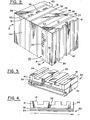
- Figure 2 is perspective view of a portion of the fuel cell assembly of Figure 1 illustrating an individual fuel cell in greater detail.
- Figure 3 ic a perspective view in partial cross- section showing a corrosion resistant interface arrangement between a gas distribution plate and a cooling plate.
- Figure 4 is a schematic exploded view of the arrangement forming the interface of Figure 3.
- An exemplary fuel
cell stack assembly 10 employing a plurality of fuel cells 11 in accordance with this invention is now described with reference to Figures 1 and 2. Hydrogengas input manifolds 12 are arranged along one side of thestack assembly 10. While a plurality ofmanifolds 12 are shown for each group of fuel cells 11, if desired, a single manifold arrangement could be used. Themanifolds 12 are connected to a source ofhydrogen gaf 14. Hydrogengas collecting manifolds 15 are arranged along the opposing stack side in correspondence with thegas input manifolds 12. Here again, while a plurality ofmanifolds 15 are shown, a single manifold could be used if desired. Thecollecting manifolds 15, are, in turn, connected to a hydrogengas discharging system 17. The hydrogen gas from theinput manifolds 12 flows throughgas distribution plates 18 to the collectingmanifolds 15. - In a similar fashion, a plurality of oxygen or air input manifolds (not shown) are arranged along the stack side (not shown) connecting the one stack side and the opposing stack side. The oxygen manifolds are connected to an
oxygen source 19. The oxygen may be supplied in the form of air rather than pure oxygen if desired. In a similar fashion, a plurality of collecting manifolds are arranged along the stack side (not shown) opposing the stack side having the oxygen input manifolds and connecting the respective one stack side and opposing stack side. These manifolds would also be connected to an oxygen storage or recirculating system (not shown). The oxygen or air from the input manifolds (not shown) flows through the oxygengas distribution plates 20 to the respective collecting manifolds (not shown). - In this embodiment,
cooling plates 21 are arranged periodically between adjacent fuel cells 11. Threecooling plates 21 are shown arranged intermediate each four cell 11 array. The cooling fluid flo ing through thecooling plates 21 is preferably a dielectric fluid, such as a high temperature oil, such an oil being manufactured by Monsanto under the trade name, Therminol. Apump 22 circul: tes the dielectric fluid via conduit 23 andinput manifold 24 into therespective cooling plates 21. The dielectric fluid then flows into collectingmanifold 25 which is connected to aheat exchanger 26 for reducing the temperature of the dielectric fluid to the desired input temperature. Aconduit 27 then connects the heat exchanger back to thepump 22 so that the fluid can be recirculated through therespective cooling plates 21. - The fuel cells 11 and the
cooling plates 21 are electrically conductive so that when they are stacked as shown, the fuel cells 11 are being connected in series. In order to connect thestack assembly 10 to a desired electrical load,current collecting plates 28 are employed at the respective ends of thestack assembly 10.Positive terminal 29 andnegative terminal 30 are connected to the current connectingplates 28 as shown and may be connected to the desired electrical load by any conventional means. - Each fuel cell 11 is made up of a plurality of elements and includes a hydrogen
gas distribution plate 18 and an oxygen orair distribution plate 20. Arranged intermediate the respectivegas distribution plates anode 31,anode catalyst 32,electrolyte 33,cathode catalyst 34 andcathode 35. These elements 31-35 of the fuel cell 11 may be formed of any suitable material in accordance with conventional practice. - The hydrogen
gas distribution plate 18 is arranged in contact withanode 31. Typically, the anode comprises a carbon material having pores which allow the hydrogen fuel gas to pass through the anode to theanode catalyst 32. Theanode 31 is preferably treated with Teflon (polytetrafluoroethylene) to prevent theelectrolyte 33, which is preferably an immobilized acid, from flooding back into the area of the anode. If flooding were allowed to occur, the electrolyte would plug up the pores in theanode 31 and lessen the flow of hydrogen fuel through the cell 11. Theanode catalyst 32 is preferably a platinum containing catalyst. - The cell 11 is formed of an electrically conductive material, such as a carbon based material, except for the immobilized acid electrolyte layer which does not conduct electrons but does conduct hydrogen ions. The various elements, 18, 31-35, and 20 are compressed together under a positive pressure. The
electrolyte 33, such as phosphoric acid, is immobilized by being dispersed in a gel or paste matrix so that the acid is not a free liquid. An exemplary electrolyte matrix could comprise a mixture of phosphoric acid, silicon carbide particles and Teflon particles. - The
cathode catalyst 34 and thecathode 35 are formed of the same types of materials as therespective anode catalyst 32 andanode 31. Therefore, theanode 31 and thecathode 35 comprise porous carbon and theanode catalyst 32 andcathode catalyst 34 can comprise a platinum containing catalyst. Thecathode 35 can also be treated with Teflon to prevent the electrolyte from flooding back into the porous carbon comprising the cathode. - All of the elements of the cell 11 are arranged in intimate contact as shown in Figure 2. In order to provide an electrically
interconnected stack assembly 10,bi-polar asembly 36 is used to connect together adjacent fuel cells 11. Abi-polar assembly 36 is comprised of a hydrogengas distribution plate 18 and an oxygen orair distribution plate 20 with an impervious interface layer orplate 37 arranged between them. Therefore, abi-polar assembly 36 is comprised of the hydrogengas distribution plate 18 of one cell 11 and the oxygen or airgas distribution plate 20 of the next adjacent cell 11. The interface layer orplate 37 may comprise an impervious carbon plate or any other conventional interface as may be desired. In thebi-polar assembly 36, therespective plates interface 37 therebetween, are securely connected together as a unit so as to have good electrical conductivity. - In order to facilitate the gas flow in the
gas distribution plates grooves grooves 38 in the hydrogengas distribution plate 18 are arranged orthogonally or perpendicularly to thegrooves 39 in the oxygen or airgas distribution plate 20. This allows the grooves to be easily connected to respective input andoutput manifolds cell stack assembly 10. - Although grooves within a particular plate, such as
plates grooves - The
gas distribution plates respective anode 31 orcathode 35. In order to more evenly distribute the respective gases at theanode 31 orcathode 35 plate surfaces, thegas distribution plates plates respective channels respective anode 31 orcathode 35. - The
current collecting plate 28 can be combined in anassembly 40 with agas distribution plate 18, as shown in Figure 2. Since thecurrent collecting plate 28 is normally formed of an impervious material, such as aluminum, the purpose of the layer orplate 60 is to prevent corrosion of theplate 28. A cooling plate assembly, shown as 21 in Figure 1, can be made in a similar manner comprising a gas distribution plate and a cooling plate with an interface layer or plate therebetween. - Referring now to Figures 3 and 4, an
improved interface layer 60 will be described. Interface layers 60 are typically employed betweengas distribution plates cooling plates 21 orcurrent collecting plates 28. The cooling plates and current collecting plates are generally formed of metal which is subject to corrosion by the acid ofelectrolyte 33. - In the prior art fuel cell stacks 10, phosphoric acid perreating from a fuel cell 11 through the
interface layer 60 into the areas of a copper-platedcooling plate 21 would tend to corrode it. Corrosion of the coolingplate 21 tends to increase the resistance of thefuel cell stack 10. In the process, corrosion products also can eventually work back to the catalyst and can poison it. The coolingplates 21 should be conductive and non-corroding; however, this is a difficult combination to achieve. The interface layers of the prior art employed Grafoil which can becom. penetrated by theelectrolyte 33 as the cell ages over the long term. It is also an expensive material and can become more porous over time due to exposure to the electrolyte. - In accordance with the invention, a new improved
interface layer configuration 60 for use intermediategas distribution plates cooling plates 21 or current collectingplate 28 in afuel cell stack 10 serves to prevent corrosion by the acid of theelectrolyte 33. As a result, electrical conduction through theinterface 60 is preserved and poisoning of the catalyst layers 32 or 34 by corrosion products is avoided. - The
improved interface layer 60 comprises aconductive layer 52 preferably comprising porou: carbon fiber paper, most preferably comprising a fluoropolymer-treated carbon paper. The coolingplate 21 or current collectingplate 28 is provided with a non-cupreous metal coating (not shown), advantageously ranging in thickness from about 0.1 mil to about 1.0 mil. The metal is preferably one selected from the group consisting of silver, gold, ruthenium, platinum, rhodium, iridium, ruthenium-nickel or palladium-nickel or a mixture thereof. The non-cupreous metal coating is formed on thecooling plate 21 or current collectingplate 28 by any convenient technique, such as by electroplating and the like. - Intermediate the
conductive layer 52 is a layer ofresin material 54. The assembly is then hot-pressed onto the metal-coatedcooling plate 21 or the metal-coatedcurrent collecting plate 28. Theresin material 54 will have filled substantially any pores in the carbon paper. This process prevents access of the electrolyte 33 - or of air to the interfacial zone. In this manner, electrical conduction is achieved while corrosion is inhibited or prevented. - A preferred resin material comprises polyethersulfone and the hot pressing is preferably carried out at from about 100 to about 300 psi and from about 500 degrees to about 750 degrees F. The resultant structure is as shown in Figure 3 wherein the carbon paper is securely bonded and electrically connected to the
cooling plate 21 and compressed against thegas distribution plate 18. - A variety of metal coatings were evaluated for their corrosion resistance; the metals were silver, gold, ruthenium, ruthenium-nickel and palladium-nickel. All of these coatings showed better corrosion resistance as compared to copper (used in the prior art). However, in order to ensure an endurance such as in the range of five years or more, additional corrosion protection is achieved by providing an additional layer of fluoropolymer-treated carbon paper. The fluoropolymer prevents or inhibits the wetting of the carbon paper by the corrosive electrolyte, thus limiting the possibility of contact between the metallic part and the electrolyte.
- The fluoropolymer-treated carbon paper is bonded to the metallic part (cooling
plate 21 or current collector plate 28) which has been precoated with one of the above-mentioned metal coatings via the film bonding process described above. An example of such process conditions includes hot pressing at 700 degrees F for 45 minutes at a pressure of about 200 psi, followed by cooling to 400 degrees F at the same pressure and further cooling to room temperature without pressure. - By utilizing this improved structure, the copper screen used in the prior art is not necessary and may be eliminated. The reason for this is that silver and other noble metals do not normally form an electrically insulating film on their surface, as do copper or aluminum under many environmental conditions. Since the function of the screen was in part at least, to break through the insulating film, the screen is no longer needed. This in turn removes a target for corrosion and also results in a less vulnerable seal against the acid electrolyte. The excess resin is being compressed according to this invention directly into the pores of the treated carbon paper, thus further reducing its porosity and limiting the possibility of contact between the electrolyte and the metallic part.
- Silver is advantageously employed as the metal coating due to its relatively low price. Samples prepared utilizing silver coating and fluoropolymer-treated paper showed the lowest corrosion current when compared to a sample utilizing copper eating and fluoropolymer-treated carbon paper. Ruthenium is also preferred, in view of its relatively low cost and the potential of superior corrosion protection observed in the tests.
- A current collector 2 ft2 was prepared according to this invention. The collector was provided with an electroplated metal coating of silver having a thickness of 0.25 mils. Fluoropolymer-treated carbon paper was bonded to the collector using polyethersulfone as the resin, employing hot pressing. The same conditions and parameters for hot pressing as descussed above were used. The current collector and interface were incorporated into a fuel cell stack and tested for 1500 hours. The current collector was re-examined after the conclusion of this test. No corrosion was detected.
- While carbon paper is a preferred conductive layer material, other materials which could be employed comprise wet proofed carbon paper, vitreous carbon, molded carbon plates, and corrosion resistant foil material such as gold. While polyethersulfone is a preferred resinous layer material, other resinous materials which could be employed comprise polyphenylsulfone, fluorinated polymers such as PTFE, fluorinated ethylene propylene, and perfluoralkoxy polymers and other corrosion resistant thermoplastic materials.
- This invention may be embodied in other forms or carried out in other ways without departing from the spirit or essential characteristics thereof. The present embodiments are therefore to be considered as in all respects illustrative and not restrictive, the scope of the invention being indicated by the appended claims, and all changes which come within the meaning and range of equivalency being intended to be embraced therein.
Claims (12)
1. A fuel cell stack comprising a plurality of stacked elements, including at least one corrosion resistant, electrically conductive, fluid impervious interface arranged between two of said elements which are adjacent to one another, said interface comprising a non-cupreous metal coating formed on at least one of said elements and a conductive layer bonded to at least said metal-coated element by a hot-pressed resin, said resin substantially filling any pores in said conductive layer.
2. A fuel cell stack as in Claim 1 wherein one of said two elements comprises a gas distribution plate and wherein the other of said two elements comprises a metal-coated cooling plate.
3. A fuel cell stack as in Claim 1 wherein one of said two elements comprises a gas distribution plate and wherein the other of said two elements comprises a metal-coated current collecting plate.
any of to 3 4. A fuel cell stack as in/Claimsl/wherein said conductive layer comprises carbon paper and said resin comprises polyethersulfone.
5. A fuel cell stack as in Claim 4 wherein said conductive layer comprises carbon paper treated with a fluoropolymer.
any preceding 6. A fuel cell stack as in/Claim wherein said metal coating is selected from the group consisting of silver, gold, ruthenium, ruthenium-nickel and palladium-nickel and combinations thereof.
7. A process for forming a corrosion resistant, electrically conductive, fluid impervious interface between two adjacent elements of a fuel cell comprising:
(a) coating at least one 3f said elements with a non-cupreous metal;
(b) arranging between said elements a conductive layer and a resin layer between said conductive layer and said metal-coated element; and
(c) hot pressing together said two elements having said layers therebetween so that a bonded, bridging electrical contact is provided between said conductive layer and the metal-coated surface of at least one of said two elements and so that said resin substantially fills the pores of said conductive layer.
8. A process as in Claim 7 wherein said hot pressing is carried out at a pressure of from about 100 to about 300 psi and at a temperature of fiom about 500 to about 750 degrees F.
Claim 7 or 9. A process as in /Claim 8 wherein said conductive layer comprises carbon paper and said resin comprises polyethersulfone.
any of to 9 10. A process as in/Claims7/wherein one of said two elements comprises a gas distribution plate and wherein the other of said two elements comprises a cooling plate.
any of to 9 11. A process as in/Claims7/wherein one of said two elements comprises a gas distribution plate and wherein the other of said two elements comprises a current collecting plate.
any of to 11 12. A process as in/Claims7/wherein said metal is selected from the group consisting of silver, gold, ruthenium, ruthenium-nickel and palladium-nickel and combinations thereof.
Applications Claiming Priority (2)
| Application Number | Priority Date | Filing Date | Title |
|---|---|---|---|
| US644822 | 1984-08-27 | ||
| US06/644,822 US4605602A (en) | 1984-08-27 | 1984-08-27 | Corrosion protected, multi-layer fuel cell interface |
Publications (1)
| Publication Number | Publication Date |
|---|---|
| EP0176247A1 true EP0176247A1 (en) | 1986-04-02 |
Family
ID=24586479
Family Applications (1)
| Application Number | Title | Priority Date | Filing Date |
|---|---|---|---|
| EP85306023A Withdrawn EP0176247A1 (en) | 1984-08-27 | 1985-08-23 | Corrosion protected, multi-layer fuel cell interface |
Country Status (4)
| Country | Link |
|---|---|
| US (1) | US4605602A (en) |
| EP (1) | EP0176247A1 (en) |
| JP (1) | JPH0654672B2 (en) |
| CA (1) | CA1250016A (en) |
Cited By (3)
| Publication number | Priority date | Publication date | Assignee | Title |
|---|---|---|---|---|
| EP0330124A2 (en) * | 1988-02-24 | 1989-08-30 | Toray Industries, Inc. | Electroconductive integrated substrate and process for producing the same |
| US4913706A (en) * | 1988-09-19 | 1990-04-03 | International Fuel Cells Corporation | Method for making a seal structure for an electrochemical cell assembly |
| DE19640805C1 (en) * | 1996-10-02 | 1998-06-18 | Siemens Ag | High temperature fuel cell stack production |
Families Citing this family (12)
| Publication number | Priority date | Publication date | Assignee | Title |
|---|---|---|---|---|
| JPH0626126B2 (en) * | 1986-06-13 | 1994-04-06 | 株式会社日立製作所 | Fuel cell |
| JP3028488B2 (en) * | 1989-11-20 | 2000-04-04 | トヨクニ電線株式会社 | Emergency communication installation method and emergency communication cable |
| US5478676A (en) * | 1994-08-02 | 1995-12-26 | Rexam Graphics | Current collector having a conductive primer layer |
| JP4366872B2 (en) * | 2000-03-13 | 2009-11-18 | トヨタ自動車株式会社 | FUEL CELL GAS SEPARATOR, METHOD FOR PRODUCING THE FUEL CELL SEPARATOR, AND FUEL CELL |
| EP1394879B1 (en) * | 2001-05-08 | 2006-08-23 | Ube Industries, Ltd. | Polymer electrolyte for solid polymer type fuel cell and fuel cell |
| AU2002359273A1 (en) * | 2001-10-17 | 2003-04-28 | Trustees Of Boston University | One-step consolidation process for manufacturing solid oxide fuel cells |
| DE10158771C2 (en) * | 2001-11-23 | 2003-09-18 | Reinz Dichtungs Gmbh & Co Kg | The fuel cell system |
| JP4986623B2 (en) * | 2003-06-09 | 2012-07-25 | サン−ゴバン セラミックス アンド プラスティクス,インコーポレイティド | Solid oxide fuel cell stack and fuel cell system |
| RU2008127752A (en) * | 2006-01-09 | 2010-02-20 | Сэнт-Гобэн Керамикс Енд Пластикс, Инк. (Us) | COMPONENT WITH A SOLID-OXIDE FUEL ELEMENT (OPTIONS) AND METHOD FOR ITS FORMATION |
| CA2647414C (en) * | 2006-04-05 | 2012-10-30 | Saint-Gobain Ceramics & Plastics, Inc. | A sofc stack having a high temperature bonded ceramic interconnect and method for making same |
| CN101884125B (en) | 2007-10-26 | 2013-11-20 | 赛昂能源有限公司 | Primer for battery electrode |
| FR3040240B1 (en) * | 2015-08-19 | 2017-08-04 | Commissariat Energie Atomique | FUEL CELL WITH INTEGRATED WATER MANAGEMENT LAYER AND METHOD FOR PRODUCING THE SAME |
Citations (4)
| Publication number | Priority date | Publication date | Assignee | Title |
|---|---|---|---|---|
| DE2250187A1 (en) * | 1972-10-13 | 1974-04-25 | Varta Batterie | LEAD ACCUMULATOR WITH BIPOLAR ELECTRODES |
| US4115627A (en) * | 1977-08-15 | 1978-09-19 | United Technologies Corporation | Electrochemical cell comprising a ribbed electrode substrate |
| EP0106603A1 (en) * | 1982-09-30 | 1984-04-25 | Engelhard Corporation | Film bonded fuel cell interface configuration |
| EP0122150A2 (en) * | 1983-04-11 | 1984-10-17 | Engelhard Corporation | Integral gas seal for fuel cell gas distribution assemblies and method of fabrication |
Family Cites Families (1)
| Publication number | Priority date | Publication date | Assignee | Title |
|---|---|---|---|---|
| US4526843A (en) * | 1982-09-30 | 1985-07-02 | Engelhard Corporation | Film bonded fuel cell interface configuration |
-
1984
- 1984-08-27 US US06/644,822 patent/US4605602A/en not_active Expired - Lifetime
-
1985
- 1985-08-23 EP EP85306023A patent/EP0176247A1/en not_active Withdrawn
- 1985-08-26 CA CA000489388A patent/CA1250016A/en not_active Expired
- 1985-08-26 JP JP60185958A patent/JPH0654672B2/en not_active Expired - Lifetime
Patent Citations (4)
| Publication number | Priority date | Publication date | Assignee | Title |
|---|---|---|---|---|
| DE2250187A1 (en) * | 1972-10-13 | 1974-04-25 | Varta Batterie | LEAD ACCUMULATOR WITH BIPOLAR ELECTRODES |
| US4115627A (en) * | 1977-08-15 | 1978-09-19 | United Technologies Corporation | Electrochemical cell comprising a ribbed electrode substrate |
| EP0106603A1 (en) * | 1982-09-30 | 1984-04-25 | Engelhard Corporation | Film bonded fuel cell interface configuration |
| EP0122150A2 (en) * | 1983-04-11 | 1984-10-17 | Engelhard Corporation | Integral gas seal for fuel cell gas distribution assemblies and method of fabrication |
Cited By (4)
| Publication number | Priority date | Publication date | Assignee | Title |
|---|---|---|---|---|
| EP0330124A2 (en) * | 1988-02-24 | 1989-08-30 | Toray Industries, Inc. | Electroconductive integrated substrate and process for producing the same |
| EP0330124A3 (en) * | 1988-02-24 | 1991-06-12 | Toray Industries, Inc. | Electroconductive integrated substrate and process for producing the same |
| US4913706A (en) * | 1988-09-19 | 1990-04-03 | International Fuel Cells Corporation | Method for making a seal structure for an electrochemical cell assembly |
| DE19640805C1 (en) * | 1996-10-02 | 1998-06-18 | Siemens Ag | High temperature fuel cell stack production |
Also Published As
| Publication number | Publication date |
|---|---|
| JPH0654672B2 (en) | 1994-07-20 |
| US4605602A (en) | 1986-08-12 |
| CA1250016A (en) | 1989-02-14 |
| JPS61114477A (en) | 1986-06-02 |
Similar Documents
| Publication | Publication Date | Title |
|---|---|---|
| US4605602A (en) | Corrosion protected, multi-layer fuel cell interface | |
| US4505992A (en) | Integral gas seal for fuel cell gas distribution assemblies and method of fabrication | |
| US5707755A (en) | PEM/SPE fuel cell | |
| US4588661A (en) | Fabrication of gas impervious edge seal for a bipolar gas distribution assembly for use in a fuel cell | |
| US7390586B2 (en) | Fuel cell stacks of alternating polarity membrane electrode assemblies | |
| EP0750798B1 (en) | Solid oxide fuel cell stacking assembly | |
| CA1065395A (en) | Fuel cell cooling system | |
| US7858262B2 (en) | Fuel cell comprising a plurality of individual cells connected in series by current collectors | |
| US5776624A (en) | Brazed bipolar plates for PEM fuel cells | |
| US6132895A (en) | Fuel cell | |
| EP1009051A2 (en) | Liquid cooled bipolar plate consisting of glued plates for PEM fuel cells | |
| US3575718A (en) | Composite electrolyte member for fuel cell | |
| CA2203015A1 (en) | Cathode reactant flow field component for a fuel cell stack | |
| EP1298755B1 (en) | Fuel cell stack having foil interconnects and laminated spacers | |
| CN101087030A (en) | Method for making a hydrophilic corrosion resistant coating on low grade stainless steel/alloys for bipolar plates | |
| US4526843A (en) | Film bonded fuel cell interface configuration | |
| US4938833A (en) | Process for making film-bonded fuel cell interfaces | |
| DE102007022202B4 (en) | Fuel cell stack with a non-permeable insert with low contact resistance | |
| CA1202064A (en) | Film bonded fuel cell interface configuration | |
| US4826716A (en) | Film bonded fuel cell interface configuration | |
| US4461813A (en) | Electrochemical power generator | |
| Pigeaud et al. | Coating applications for the molten carbonate fuel cell | |
| JPS60167274A (en) | Fuel cell |
Legal Events
| Date | Code | Title | Description |
|---|---|---|---|
| PUAI | Public reference made under article 153(3) epc to a published international application that has entered the european phase |
Free format text: ORIGINAL CODE: 0009012 |
|
| AK | Designated contracting states |
Kind code of ref document: A1 Designated state(s): AT BE CH DE FR GB IT LI LU NL SE |
|
| STAA | Information on the status of an ep patent application or granted ep patent |
Free format text: STATUS: THE APPLICATION IS DEEMED TO BE WITHDRAWN |
|
| 18D | Application deemed to be withdrawn |
Effective date: 19861003 |
|
| RIN1 | Information on inventor provided before grant (corrected) |
Inventor name: WANG, CHIU LING Inventor name: FEIGENBAUM, HAIM Inventor name: PUDICK, SHELDON |