EP0176168A2 - Bottom supported basket - Google Patents
Bottom supported basket Download PDFInfo
- Publication number
- EP0176168A2 EP0176168A2 EP85303188A EP85303188A EP0176168A2 EP 0176168 A2 EP0176168 A2 EP 0176168A2 EP 85303188 A EP85303188 A EP 85303188A EP 85303188 A EP85303188 A EP 85303188A EP 0176168 A2 EP0176168 A2 EP 0176168A2
- Authority
- EP
- European Patent Office
- Prior art keywords
- basket
- mounting portion
- frame
- side panels
- panel
- Prior art date
- Legal status (The legal status is an assumption and is not a legal conclusion. Google has not performed a legal analysis and makes no representation as to the accuracy of the status listed.)
- Withdrawn
Links
- 230000008878 coupling Effects 0.000 claims description 28
- 238000010168 coupling process Methods 0.000 claims description 28
- 238000005859 coupling reaction Methods 0.000 claims description 28
- 230000013011 mating Effects 0.000 claims description 5
- 238000004873 anchoring Methods 0.000 claims 1
- 239000004033 plastic Substances 0.000 abstract description 17
- 229920003023 plastic Polymers 0.000 abstract description 17
- 238000010276 construction Methods 0.000 description 7
- 239000002184 metal Substances 0.000 description 7
- 229910052751 metal Inorganic materials 0.000 description 7
- 238000007747 plating Methods 0.000 description 5
- 230000003014 reinforcing effect Effects 0.000 description 5
- 239000004698 Polyethylene Substances 0.000 description 4
- -1 polyethylene Polymers 0.000 description 4
- 229920000573 polyethylene Polymers 0.000 description 4
- 239000007787 solid Substances 0.000 description 4
- 230000006378 damage Effects 0.000 description 3
- 230000008439 repair process Effects 0.000 description 3
- 239000010953 base metal Substances 0.000 description 2
- 230000008901 benefit Effects 0.000 description 2
- 238000004140 cleaning Methods 0.000 description 2
- 230000000694 effects Effects 0.000 description 2
- JEIPFZHSYJVQDO-UHFFFAOYSA-N iron(III) oxide Inorganic materials O=[Fe]O[Fe]=O JEIPFZHSYJVQDO-UHFFFAOYSA-N 0.000 description 2
- 239000000463 material Substances 0.000 description 2
- 238000000034 method Methods 0.000 description 2
- 230000008569 process Effects 0.000 description 2
- 230000002787 reinforcement Effects 0.000 description 2
- VYZAMTAEIAYCRO-UHFFFAOYSA-N Chromium Chemical group [Cr] VYZAMTAEIAYCRO-UHFFFAOYSA-N 0.000 description 1
- 208000027418 Wounds and injury Diseases 0.000 description 1
- 238000005452 bending Methods 0.000 description 1
- 230000003749 cleanliness Effects 0.000 description 1
- 239000003086 colorant Substances 0.000 description 1
- 239000000356 contaminant Substances 0.000 description 1
- 230000007797 corrosion Effects 0.000 description 1
- 238000005260 corrosion Methods 0.000 description 1
- 230000007812 deficiency Effects 0.000 description 1
- 239000003599 detergent Substances 0.000 description 1
- 230000003670 easy-to-clean Effects 0.000 description 1
- 235000007983 food acid Nutrition 0.000 description 1
- 230000003116 impacting effect Effects 0.000 description 1
- 208000014674 injury Diseases 0.000 description 1
- 230000007257 malfunction Effects 0.000 description 1
- 150000002739 metals Chemical class 0.000 description 1
- 238000012986 modification Methods 0.000 description 1
- 230000004048 modification Effects 0.000 description 1
- 239000002245 particle Substances 0.000 description 1
- 239000002990 reinforced plastic Substances 0.000 description 1
- 238000007790 scraping Methods 0.000 description 1
- 238000003860 storage Methods 0.000 description 1
- 238000005728 strengthening Methods 0.000 description 1
- 238000003466 welding Methods 0.000 description 1
Images


Classifications
-
- B—PERFORMING OPERATIONS; TRANSPORTING
- B62—LAND VEHICLES FOR TRAVELLING OTHERWISE THAN ON RAILS
- B62B—HAND-PROPELLED VEHICLES, e.g. HAND CARTS OR PERAMBULATORS; SLEDGES
- B62B3/00—Hand carts having more than one axis carrying transport wheels; Steering devices therefor; Equipment therefor
- B62B3/14—Hand carts having more than one axis carrying transport wheels; Steering devices therefor; Equipment therefor characterised by provisions for nesting or stacking, e.g. shopping trolleys
-
- B—PERFORMING OPERATIONS; TRANSPORTING
- B62—LAND VEHICLES FOR TRAVELLING OTHERWISE THAN ON RAILS
- B62B—HAND-PROPELLED VEHICLES, e.g. HAND CARTS OR PERAMBULATORS; SLEDGES
- B62B2501/00—Manufacturing; Constructional features
- B62B2501/06—Materials used
- B62B2501/065—Plastics
-
- Y—GENERAL TAGGING OF NEW TECHNOLOGICAL DEVELOPMENTS; GENERAL TAGGING OF CROSS-SECTIONAL TECHNOLOGIES SPANNING OVER SEVERAL SECTIONS OF THE IPC; TECHNICAL SUBJECTS COVERED BY FORMER USPC CROSS-REFERENCE ART COLLECTIONS [XRACs] AND DIGESTS
- Y10—TECHNICAL SUBJECTS COVERED BY FORMER USPC
- Y10S—TECHNICAL SUBJECTS COVERED BY FORMER USPC CROSS-REFERENCE ART COLLECTIONS [XRACs] AND DIGESTS
- Y10S280/00—Land vehicles
- Y10S280/04—Grocery store cart
Definitions
- the present invention relates generally to the field of wheeled carts such as to those used as grocery shopping carts in supermarkets and the like, and more particularly, is directed to a new and improved bottom-supported basket having coupling means for quickly and releasably coupling the basket to a frame or chassis.
- carts of this type should have the following characteristics. First, they should be able to withstand a great deal of abuse, particularly to the basket portion. Carts are continuously impacted with one another and with stationary objects. Second, the carts should be easy to push and to maneuver. The condition of the wheels has a great effect on this characteristic, but so does the weight of the cart. Third, the carts should be of such design and such surface finish as not to have a propensity to collect dirt and contaminants. Fourth, the carts should be able to withstand cleaning by strong detergents or steam. Fifth, the carts usually must have sides of openwork construction, because customers wish to be able to observe the contents of the carts from any angle. Sixth, the carts should be attractive and should maintain their attractiveness over a long period of time.
- the carts present in the prior art comprise a tubular metal frame to which is attached a basket of open wire-work construction.
- the wires are in various crossing patterns, and they are usually welded together at the crossing points. Heavier wire reinforcement is used where necessary.
- the cart frame and the basket are integral with one another. That is, the basket wires and the frame components are welded together at appropriate points, or the wires are interlocked with the frame components.
- the entire cart is chrome plated. Sometimes plastic or rubber bumpers are installed at strategic points, such as corners.
- the prior art carts do not satisfy all of the requirements set forth above.
- the deficiencies have chiefly to do with the basket portion.
- the wires in the basket are welded at the crossing points, and the basket is then chrome-plated, the latter to provide a smooth, cleanable, attractive surface.
- the welding process for such an item is intricate, as is the plating process. It is therefore not uncommon to have welds and plating of marginal quality so that, upon hard impact, or upon a series of impacts over a period of time, wire welds and the plating are broken.
- the plating is also subject to being removed by wear and by scraping against other objects. This allows the base metal to rust.
- Prior art carts are also quite heavy, making them difficult to push and to maneuver, especially if they have some malfunction of the wheels.
- a specific object of the present invention is to provide a new and improved basket which is not easily damaged by impact.
- Another specific object of the present invention is to provide a new and improved basket which is easy to clean.
- Another specific object of the present Invention is to provide a new and improved basket which can be quickly and releasably mounted to a cart frame.
- a further specific object of the present invention is to provide a new and improved basket which is lighter in weight than baskets known in the prior art.
- a still further specific object of the present invention is to provide a new and improved basket which can be nested and mmested.
- Another specific object of the present Invention is to provide a new and improved basket which when mounted to a cart frame provides a cart which is less noisy than carts known in the prior art.
- Another specific object of the present invention is to provide a new and improved basket which is more attractive than prior art baskets, and which maintains this attractiveness over a long period of time.
- a still further specific object of the present invention is to provide a new and improved basket which may be mounted on a plastic chassis or may be mounted on a conventional metal frame chassis.
- Another specific object of the present invention is to provide a new and improved basket which can be quickly and releasably coupled to a cart frame.
- a still further specific object of the present invention is to provide a new and improved basket which has a rear panel retaining means which positively prevents the rear panel from pivoting outwardly from the rear edge of the sidewalls of the basket to prevent injury to a child sitting in a child seat attached to the rear panel.
- Another specific object of the present invention is to provide a new and improved basket which is more practical to use as a shopping cart when attached to a cart frame.
- Another specific object of the present invention is to provide a new and improved basket which has a downwardly stepped rear portion which permits the basket to have a larger holding capacity.
- a still further specific object of the present invention is to provide a new and improved basket which has a novel coupling means which permits quick coupling and decoupling of the basket to a frame or chassis.
- Another specific object of the present invention is to provide a new and improved basket design and handle assembly which can be easily decoupled from each other without the need for removing reinforcing wires from the basket or handle assembly.
- the basket in accordance with the present invention is made of plastic, such as polyethylene, which is strong, light-weight, has a smooth finish, and can deform somewhat to absorb impact and then return to its original shape.
- the sides, front and bottom of the plastic basket are integrally molded in one piece. Thus there are no seams to break, or cracks and crevices to collect dirt.
- the plastic does not rust or corrode under the influence of food acids and the like.
- the use of a plastic basket has been found to reduce the weight of an average cart by at least fifteen pounds.
- the basket is almost entirely of open lattice construction, which further lightens it, and which allows the contents of the basket to be viewed from any angle. Rigidity is provided to the basket by the use of suitable integral strengthening ribs, and also by a novel interrelationship between the basket and the cart frame.
- the rearmost edges of each side panel of the basket are contoured in cross-section to mate with the configuration of the upstanding handle posts which support the handle. This provides vertical stiffness to the basket structure, without the inclusion of additional members.
- the basket is designed, however, to also receive metal ring means that extend around the basket and engage the handle posts.
- the ring means press the rear edges of the basket sides against the posts. This also adds rigidity to the basket.
- the ring means preferrably comprises an endless ring that encircles the basket and the handle posts.
- the bottom panel of the basket includes coupling means for quickly and releasably coupling the basket to a cart frame having corresponding coupling means.
- the coupling means includes mating male and female locking elements respectively located on the frame and basket which permit the basket to be quickly coupled to the frame.
- damage to the basket does not require that the entire cart be discarded.
- a damaged basket may be quickly removed and a new basket installed on the cart frame.
- the bottom panel of the basket also includes conventional mounting elements which may be used to couple the basket to a conventional metal cart frame with bolts, rivets and the like.
- Another feature of the basket is that it has a downwardly stepped rear portion which permits the basket to have a large holding capacity while permitting nesting and customer convenience in removing articles from the basket.
- a further important feature of the basket in accordance with the present invention is the presence of retaining means which positively prevent the rear panel from pivoting outwardly from the rear edge of the side walls of the basket.
- the rear edge of the bottom panel of the basket is provided with a raised transverse cross member which extends along the full width of the rear edge of the bottom panel to retain the rear panel.
- the upper edge of the cross member coincides with the plane of the front portion of the bottom panel to permit nesting.
- plastic basket can be made in a variety of bright colors. This makes the cart more attractive. It also makes the cart more visible, which reduces accidents both inside the store and outside on the parking lot.
- a further advantage of the basket in accordance with the invention is the addition of a removable reinforced plastic handle which is releasably anchored between the upper edges of the frame mounting portion and the lower edge of the basket mounting portion.
- the basket in accordance with the present invention is comprised of a number of interrelated elements. Each of which will be a explained in detail below.
- the basket comprises a front panel, two side panels and a bottom panel integrally molded with one another.
- a rear panel is positioned between the two side panels in opposed relationship to the front panel and is pivotable between the two side panels to permit nesting of a plurality of baskets.
- a retaining rail is integrally molded along the rear edge of the bottom panel to prevent the rear panel from pivoting rearwardly from beyond the rear edge of the bottom panel.
- An important feature of the basket in accordance with the present invention is the presence of a basket bottom portion having a quick release coupling means engageable with a corresponding mounting portion on a chassis. The quick release coupling means permits the basket to be readily attached to or release from a corresponding chassis.
- the basket is advantegously manufactured of a plastic material such as polyethylene.
- a plastic material such as polyethylene.
- the properties of polyethylene are ideally suited to this application, for polyethylene is relatively strong, but panels manufactured of it are flexible enough to absorb some deformation, such as caused by impact, without breaking. However, other materials having similar properties can also be used.
- the basket In order to facilitate the cleaning of the basket, and to allow the user to observe the goods placed in the basket, the basket is of open lattice work construction.
- the lattice can be any one of a multitude of patterns. As shown herein, the patter is in squares.
- the basket in accordance with the present invention comprises a front panel 100 and side panels 101 and 102.
- the latticework is an overlay upon solid corner portions 104, which give rigidity and strength at key points.
- Bottom panel 103 is integrally attached to panels 100, 101 and 102. It is also of open lattice construction, except for certain solid portions. Additional solid portions 105 are also present to add strength to the side panels, and a solid portion 106 can be added for the purpose of carrying a label or advertising.
- Side panels 101 and 102 include at each of their rear edges widened sections 165, and at their forward corners widened sections 161. The function of these widened portions is to act as bumpers against adjacent objects. Widened sections 165 of the rear edges of side panels 101 and 102 terminate in a portion which is concavely curved to engage handle posts 166, 167. This adds rigidity to the plastic basket and prevents the basket from moving laterally with respect to the chassis. Other conforming configurations might also be used, however.
- channel 150 extends around the top edge of the basket, defined by a pair of horizontally extending flanges 151 and 152.
- An endless metal reinforcing ring 153 encircles the upper portion of the basket. Ring 153 is received in channel 150 which surrounds the top periphery of side panels 101 and 102 and front panel 100.
- Flange 151 is provided with a plurality of upwardly extending openings 155. Tabs on ring 153 are received in these opening 155 in order to interlock the basket 102 with ring 153.
- This arrangement is present for practically the entire length of channel 150, as illustrated in Fig. 2.
- Ring 153 extends around handle posts 166 and 167 and across the rear of the basket as shown in Figure 4. Ring 153 serves as a pivot point or hinge for rear panel 107.
- One of the novel features of this invention Is the fact the the plastic basket can easily be replaced if it Is damaged.
- one of the disadvantages of a wire basket is that, once broken, it is difficult and expensive to repair, if it can at all be repaired. If the plastic basket of this invention becomes damaged, it can easily be removed and replaced.
- the basket in accordance with the present invention includes coupling means comprising male and female locking elements respective located on the basket and frame which permit the basket to be quickly coupled to the frame.
- coupling means comprising male and female locking elements respective located on the basket and frame which permit the basket to be quickly coupled to the frame.
- the basket can be removed from the frame and replaced easily if necessary.
- the coupling means is formed on the bottom surface of bottom panel 103 and include a plurality of coupling features each of which comprise a window 200 with locking shoulder 201 as shown in Figures 17-19.
- a locking tang 202 extend upwardly from a cart frame having an upwardly facing mounting portion.
- Locking shoulder 201 receives locking surface 203 of locking tang 202 to securly engage the basket to the frame.
- a plurality of such coupling features may be located along the bottom and side surfaces of the basket to provide the requisite coupling strength.
- Bottom panel 103 also includes conventional mounting elements which may be used to couple the basket to a conventional metal cart frame with bolts and rivets.
- the basket coupling means of the invention also included a downwardly curved portion 204 which receives a tubular portion of a cart frame. The tubular portion is secured in portion 204 by a bolt or rivet extending through hole 205.
- Figure 16 illustrates the engagement of the basket of the invention with a cart frame or chassis having a corresponding mating surface.
- a chassis is described in Applicant's U.S. Patent Application S.N. 607,128 (Applicant's Attorney's Docket No. 13895 ).
- Handle posts 166 and 167 are shown In more detail in Figure 11-15. Handle posts 166, 167 are connected by handle bar 168 (Fig. 2) to form a convenient way of pushing the basket when it is attached to a chassis. Handle posts 166, 167 and handle bar 168 are also of plastic construction and may, be integrally molded. Handle bar 168 includes a flat surface 169 for receiving written information. Handle bar 168 and a portion of handle posts 166, 167 are formed with a recessed portion 301 which receives reinforcing rod 302 to provide additional strength for the assembly. Handle posts 166 and 167 each include a mounting feature 303 which engages bottom panel 103 of the basket and an upper facing portion of the chassis as shown in Figure 20. Thus when the basket is coupled to the chassis, the handle posts 166 and 167 are sandwiched between the basket and chassis and held there securely.
- bottom panel 103 includes at its rearward edge, a raised transverse cross member 401 of hollow cross-section extending along the full width of its rear edge.
- Cross member 401 is located to prevent the rear panel of the basket from pivoting rearwardly from beyond the rear edge of the bottom panel.
- cross member 401 is substantially high with respect to rear panel 107 so that rear panel 107 does not inadvertently pass the cross member.
- the extended high of cross member 401 is permitted because of the presence of stepped rear portion 110 of the basket. Were it not for step portion 110, the extended high of cross member 401 would prevent basket nesting.
- the lower contour of the basket is in two planes, a first inclined plane 111 and a second inclined plane 112 connected by a step portion 114.
- the height of cross member 401 is maintained lower than the rear edge of inclined plane 111, i.e., point 115. Since cross member 401 is carried on plane 112, which is lower than plane 111, it can be made very high without interferring with nesting of the baskets.
Abstract
Description
- The present invention relates generally to the field of wheeled carts such as to those used as grocery shopping carts in supermarkets and the like, and more particularly, is directed to a new and improved bottom-supported basket having coupling means for quickly and releasably coupling the basket to a frame or chassis.
- Ideally, carts of this type, and particularly those used in supermarkets and grocery stores, should have the following characteristics. First, they should be able to withstand a great deal of abuse, particularly to the basket portion. Carts are continuously impacted with one another and with stationary objects. Second, the carts should be easy to push and to maneuver. The condition of the wheels has a great effect on this characteristic, but so does the weight of the cart. Third, the carts should be of such design and such surface finish as not to have a propensity to collect dirt and contaminants. Fourth, the carts should be able to withstand cleaning by strong detergents or steam. Fifth, the carts usually must have sides of openwork construction, because customers wish to be able to observe the contents of the carts from any angle. Sixth, the carts should be attractive and should maintain their attractiveness over a long period of time.
- For the most part, the carts present in the prior art comprise a tubular metal frame to which is attached a basket of open wire-work construction. The wires are in various crossing patterns, and they are usually welded together at the crossing points. Heavier wire reinforcement is used where necessary. Conventionally, the cart frame and the basket are integral with one another. That is, the basket wires and the frame components are welded together at appropriate points, or the wires are interlocked with the frame components. To promote cleanliness and attractiveness, the entire cart is chrome plated. Sometimes plastic or rubber bumpers are installed at strategic points, such as corners.
- The prior art carts do not satisfy all of the requirements set forth above. The deficiencies have chiefly to do with the basket portion. The wires in the basket are welded at the crossing points, and the basket is then chrome-plated, the latter to provide a smooth, cleanable, attractive surface. The welding process for such an item is intricate, as is the plating process. It is therefore not uncommon to have welds and plating of marginal quality so that, upon hard impact, or upon a series of impacts over a period of time, wire welds and the plating are broken. The plating is also subject to being removed by wear and by scraping against other objects. This allows the base metal to rust. Also, if the basket is used in an environment where corrosion of metals is a problem, such as in grocery stores, the base metal exposed at the broken welds will corrode. The cart, and particularly the basket, then becomes unsightly and unattractive. At those same exposed points, food particles can become entrapped in small cracks and crevices, even if the baskets are periodically cleaned, resulting in an unsanitary condition. In addition, articles placed in the basket can become pinched or snared by the unsecured wires and plating, causing inconvenience for the customer and inflicting damage to the goods. Impacts also frequently cause the basket to be deformed inwardly, giving rise to all of the above problems.
- Repair of cart baskets is a problem in itself, because it is difficult to bend the wires back into shape, and it is difficult and expensive to reweld and replate them. The cart frame and the basket are often integral with one another in prior art carts, and therefore they cannot easily be taken apart to allow repair or replacement of components. To replace the basket, welds must be broken, then replaced. Or, complicated bending and interlocking of wires is necessary during disassembly and assembly. Usually, the cart is simply not repaired. When it becomes too unsightly or too unsanitary to be used, it is discarded. The loss of the entire cart for the sake of the basket is certainly uneconomical.
- While prior art plastic baskets as disclosed in Applicant's U.S. Patent No. 3,999,774 permits a more easy replacement of the basket than possible with baskets of wire construction known in the prior art, an effect is still required to uncouple the reinforcing wires from the upstanding posts of the frame. Moreover, prior art plastic basket designs do not optimize storage capacity and grocery store shopper convenience while still permitting nesting of the baskets and maintaining an aesthetically pleasing design.
- Prior art carts are also quite heavy, making them difficult to push and to maneuver, especially if they have some malfunction of the wheels.
- The prior art carts, when in prime condition, meet some of the above requirements.. However, they deteriorate rather quickly, and soon become unsatisfactory in a number of these areas.
- It is the overall object of the present invention to provide a new and improved basket for use with a wheeled cart frame which overcomes the disadvantages of prior art baskets.
- A specific object of the present invention is to provide a new and improved basket which is not easily damaged by impact.
- Another specific object of the present invention is to provide a new and improved basket which is easy to clean.
- Another specific object of the present Invention is to provide a new and improved basket which can be quickly and releasably mounted to a cart frame.
- A further specific object of the present invention is to provide a new and improved basket which is lighter in weight than baskets known in the prior art.
- A still further specific object of the present invention is to provide a new and improved basket which can be nested and mmested.
- Another specific object of the present Invention is to provide a new and improved basket which when mounted to a cart frame provides a cart which is less noisy than carts known in the prior art.
- Another specific object of the present invention is to provide a new and improved basket which is more attractive than prior art baskets, and which maintains this attractiveness over a long period of time.
- A still further specific object of the present invention is to provide a new and improved basket which may be mounted on a plastic chassis or may be mounted on a conventional metal frame chassis.
- Another specific object of the present invention is to provide a new and improved basket which can be quickly and releasably coupled to a cart frame.
- A still further specific object of the present invention is to provide a new and improved basket which has a rear panel retaining means which positively prevents the rear panel from pivoting outwardly from the rear edge of the sidewalls of the basket to prevent injury to a child sitting in a child seat attached to the rear panel.
- Another specific object of the present invention is to provide a new and improved basket which is more practical to use as a shopping cart when attached to a cart frame.
- Another specific object of the present invention is to provide a new and improved basket which has a downwardly stepped rear portion which permits the basket to have a larger holding capacity.
- A still further specific object of the present invention is to provide a new and improved basket which has a novel coupling means which permits quick coupling and decoupling of the basket to a frame or chassis.
- Another specific object of the present invention is to provide a new and improved basket design and handle assembly which can be easily decoupled from each other without the need for removing reinforcing wires from the basket or handle assembly.
- The basket in accordance with the present invention is made of plastic, such as polyethylene, which is strong, light-weight, has a smooth finish, and can deform somewhat to absorb impact and then return to its original shape. The sides, front and bottom of the plastic basket are integrally molded in one piece. Thus there are no seams to break, or cracks and crevices to collect dirt. The plastic does not rust or corrode under the influence of food acids and the like. The use of a plastic basket has been found to reduce the weight of an average cart by at least fifteen pounds.
- The basket is almost entirely of open lattice construction, which further lightens it, and which allows the contents of the basket to be viewed from any angle. Rigidity is provided to the basket by the use of suitable integral strengthening ribs, and also by a novel interrelationship between the basket and the cart frame. The rearmost edges of each side panel of the basket are contoured in cross-section to mate with the configuration of the upstanding handle posts which support the handle. This provides vertical stiffness to the basket structure, without the inclusion of additional members.
- The basket is designed, however, to also receive metal ring means that extend around the basket and engage the handle posts. The ring means press the rear edges of the basket sides against the posts. This also adds rigidity to the basket. The ring means preferrably comprises an endless ring that encircles the basket and the handle posts.
- One of the key features of this invention is the fact that the basket can be replaced, if necessary, and further, that it can be replaced quite easily. The bottom panel of the basket includes coupling means for quickly and releasably coupling the basket to a cart frame having corresponding coupling means. The coupling means includes mating male and female locking elements respectively located on the frame and basket which permit the basket to be quickly coupled to the frame. Thus, damage to the basket does not require that the entire cart be discarded. A damaged basket may be quickly removed and a new basket installed on the cart frame. The bottom panel of the basket also includes conventional mounting elements which may be used to couple the basket to a conventional metal cart frame with bolts, rivets and the like.
- Another feature of the basket is that it has a downwardly stepped rear portion which permits the basket to have a large holding capacity while permitting nesting and customer convenience in removing articles from the basket.
- A further important feature of the basket in accordance with the present invention is the presence of retaining means which positively prevent the rear panel from pivoting outwardly from the rear edge of the side walls of the basket. The rear edge of the bottom panel of the basket is provided with a raised transverse cross member which extends along the full width of the rear edge of the bottom panel to retain the rear panel. Thus, the rear panel is prevented from inadvertently pivoting rearwardly from beyond the rear edge of the bottom panel. The upper edge of the cross member coincides with the plane of the front portion of the bottom panel to permit nesting.
- Another advantage is that the plastic basket can be made in a variety of bright colors. This makes the cart more attractive. It also makes the cart more visible, which reduces accidents both inside the store and outside on the parking lot.
- A further advantage of the basket in accordance with the invention is the addition of a removable reinforced plastic handle which is releasably anchored between the upper edges of the frame mounting portion and the lower edge of the basket mounting portion. Thus, a damaged basket can be removed and a new basket and handle assembly can be replaced on an existing frame without the need to remove any reinforcing wires around the basket.
- The noise produced by movement of carts which have the basket of the invention or, by Impacting it with other carts or other objects, is considerably less than with carts having baskets known in the prior art.
-
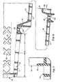
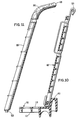
- Fig. 1 is a side elevational view of the basket with the plastic handle attached.
- Fig. 1A is a side elevational view of the basket showing the rear panel retaining member.
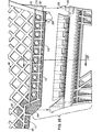
- Fig. 2 is a top plan view of the basket assembly shown in Fig. 1, with the rear panel omitted;
- Fig. 3 is a front elevational view of the basket.
- Fig.4 is a rear elevational view of the basket with the handle omitted.
- Fig. 5 is a section view taken along line 5-5 of Fig. 1.
- Fig. 6 is a sectional view taken along line 6-6 of Fig. 1.
- Fig. 7 is a sectional view taken along line 7-7 of Fig. 1.
- Fig. 8 is a sectional view taken along line 8-8 of Fig. 1.
- Fig. 9 is a sectional view taken along line 9-9 of Fig. 2.
- Fig. 10 is a sectional view taken along line 10-10 of Fig. 4.
- Fig. 11 is a side elevational view of the plastic handle.
- Fig. 12 is a rear elevational view of the handle.
- Fig. 13 is a top plane view of the handle.
- Fig. 14 is a sectional view taken along line 14-14 of Fig. 13.
- Fig. 15 is a sectional view taken along line 15-15 of Fig. 13.
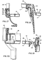
- Fig. 16 is an exploded side elevational view of the basket prior to interlocking the basket to a frame or chassis.
- Fig. 17 is a sectional view taken along line 17-17 of Fig. 16, after interlocking with a chassis, showing the interlocking of the side elements of the basket and chassis.
- Fig. 18 is a sectional view of the assembled basket and chassis taken along line 18-18 of Fig. 2.
- Fig. 19 is a sectional view of the assembled basket and chassis showing the interlocking elements at the rear of the assembly.
- Fig. 20 is a fragmentary rear elevational view of the assembly, partially in section, showing the lower end of the handle clamped between the chassis and basket.
- The basket in accordance with the present invention is comprised of a number of interrelated elements. Each of which will be a explained in detail below. Basically, the basket comprises a front panel, two side panels and a bottom panel integrally molded with one another. A rear panel is positioned between the two side panels in opposed relationship to the front panel and is pivotable between the two side panels to permit nesting of a plurality of baskets. A retaining rail is integrally molded along the rear edge of the bottom panel to prevent the rear panel from pivoting rearwardly from beyond the rear edge of the bottom panel. An important feature of the basket in accordance with the present invention is the presence of a basket bottom portion having a quick release coupling means engageable with a corresponding mounting portion on a chassis. The quick release coupling means permits the basket to be readily attached to or release from a corresponding chassis.
- The basket is advantegously manufactured of a plastic material such as polyethylene. The properties of polyethylene are ideally suited to this application, for polyethylene is relatively strong, but panels manufactured of it are flexible enough to absorb some deformation, such as caused by impact, without breaking. However, other materials having similar properties can also be used.
- In order to facilitate the cleaning of the basket, and to allow the user to observe the goods placed in the basket, the basket is of open lattice work construction. The lattice can be any one of a multitude of patterns. As shown herein, the patter is in squares.
- As shown in Figure 1, the basket in accordance with the present invention comprises a
front panel 100 andside panels solid corner portions 104, which give rigidity and strength at key points.Bottom panel 103 is integrally attached topanels solid portions 105 are also present to add strength to the side panels, and asolid portion 106 can be added for the purpose of carrying a label or advertising. - As shown in Fig. 2,
Side panels sections 165, and at their forward corners widenedsections 161. The function of these widened portions is to act as bumpers against adjacent objects.Widened sections 165 of the rear edges ofside panels handle posts - It is very important to have a strong basket, one that will withstand impact and high loading. Therefore, the basket may be provided with reinforcement. With reference again to Fig. 1 and Fig. 2,
channel 150 extends around the top edge of the basket, defined by a pair of horizontally extendingflanges metal reinforcing ring 153 encircles the upper portion of the basket.Ring 153 is received inchannel 150 which surrounds the top periphery ofside panels front panel 100.Flange 151 is provided with a plurality of upwardly extendingopenings 155. Tabs onring 153 are received in theseopening 155 in order to interlock thebasket 102 withring 153. This arrangement is present for practically the entire length ofchannel 150, as illustrated in Fig. 2.Ring 153 extends around handleposts Ring 153 serves as a pivot point or hinge forrear panel 107. - One of the novel features of this invention Is the fact the the plastic basket can easily be replaced if it Is damaged. As mentioned in the opening paragraphs of this specification, one of the disadvantages of a wire basket is that, once broken, it is difficult and expensive to repair, if it can at all be repaired. If the plastic basket of this invention becomes damaged, it can easily be removed and replaced.
- The basket in accordance with the present invention includes coupling means comprising male and female locking elements respective located on the basket and frame which permit the basket to be quickly coupled to the frame. Thus the basket can be removed from the frame and replaced easily if necessary.
- The coupling means is formed on the bottom surface of
bottom panel 103 and include a plurality of coupling features each of which comprise awindow 200 with lockingshoulder 201 as shown in Figures 17-19. A lockingtang 202 extend upwardly from a cart frame having an upwardly facing mounting portion. Lockingshoulder 201 receives lockingsurface 203 of lockingtang 202 to securly engage the basket to the frame. A plurality of such coupling features may be located along the bottom and side surfaces of the basket to provide the requisite coupling strength. -
Bottom panel 103 also includes conventional mounting elements which may be used to couple the basket to a conventional metal cart frame with bolts and rivets. As shown in Figure 19, the basket coupling means of the invention also included a downwardlycurved portion 204 which receives a tubular portion of a cart frame. The tubular portion is secured inportion 204 by a bolt or rivet extending throughhole 205. - Figure 16 illustrates the engagement of the basket of the invention with a cart frame or chassis having a corresponding mating surface. Such a chassis is described in Applicant's U.S. Patent Application S.N. 607,128 (Applicant's Attorney's Docket No. 13895 ).
- Handle posts 166 and 167 are shown In more detail in Figure 11-15. Handle posts 166, 167 are connected by handle bar 168 (Fig. 2) to form a convenient way of pushing the basket when it is attached to a chassis. Handle posts 166, 167 and handle
bar 168 are also of plastic construction and may, be integrally molded.Handle bar 168 includes aflat surface 169 for receiving written information.Handle bar 168 and a portion ofhandle posts portion 301 which receives reinforcingrod 302 to provide additional strength for the assembly. Handle posts 166 and 167 each include a mountingfeature 303 which engagesbottom panel 103 of the basket and an upper facing portion of the chassis as shown in Figure 20. Thus when the basket is coupled to the chassis, the handle posts 166 and 167 are sandwiched between the basket and chassis and held there securely. - With reference to Figures 9 and 10,
bottom panel 103 includes at its rearward edge, a raisedtransverse cross member 401 of hollow cross-section extending along the full width of its rear edge.Cross member 401 is located to prevent the rear panel of the basket from pivoting rearwardly from beyond the rear edge of the bottom panel. As shown in Figure 10,cross member 401 is substantially high with respect torear panel 107 so thatrear panel 107 does not inadvertently pass the cross member. - The extended high of
cross member 401 is permitted because of the presence of steppedrear portion 110 of the basket. Were it not forstep portion 110, the extended high ofcross member 401 would prevent basket nesting. With reference to Fig. 1, the lower contour of the basket is in two planes, a first inclined plane 111 and a secondinclined plane 112 connected by astep portion 114. To permit nesting of the baskets, the height ofcross member 401 is maintained lower than the rear edge of inclined plane 111, i.e.,point 115. Sincecross member 401 is carried onplane 112, which is lower than plane 111, it can be made very high without interferring with nesting of the baskets. - Obviously, many modifications and variations of the above described preferred embodiment will become apparent to those skilled in the art from a reading of this disclosure. It should be realized that the invention is not limited to the particular apparatus disclosed, but its scope is intended to be governed only by the scope of the appended claims.
Claims (20)
Applications Claiming Priority (2)
| Application Number | Priority Date | Filing Date | Title |
|---|---|---|---|
| US06/607,129 US4650199A (en) | 1984-05-04 | 1984-05-04 | Bottom-supported basket |
| US607129 | 2000-06-29 |
Publications (2)
| Publication Number | Publication Date |
|---|---|
| EP0176168A2 true EP0176168A2 (en) | 1986-04-02 |
| EP0176168A3 EP0176168A3 (en) | 1987-01-07 |
Family
ID=24430949
Family Applications (1)
| Application Number | Title | Priority Date | Filing Date |
|---|---|---|---|
| EP85303188A Withdrawn EP0176168A3 (en) | 1984-05-04 | 1985-05-03 | Bottom supported basket |
Country Status (2)
| Country | Link |
|---|---|
| US (1) | US4650199A (en) |
| EP (1) | EP0176168A3 (en) |
Cited By (10)
| Publication number | Priority date | Publication date | Assignee | Title |
|---|---|---|---|---|
| EP0222480A1 (en) * | 1985-10-02 | 1987-05-20 | Madj Silzer | Shopping cart |
| EP0340358A1 (en) * | 1988-05-04 | 1989-11-08 | Rehrig International, Inc. | Cart with advertising panels |
| EP0341029A1 (en) * | 1988-05-04 | 1989-11-08 | Houston Rehrig | Advertising panel for shopping carts |
| US5111604A (en) * | 1988-05-04 | 1992-05-12 | Rehrig International, Inc. | Basket wall and placard display assembly |
| US5210968A (en) * | 1988-05-04 | 1993-05-18 | Rehrig International, Inc. | Advertising panel for shopping carts |
| US5331756A (en) * | 1988-05-04 | 1994-07-26 | Rehrig International, Inc. | Basket wall with placard display assembly |
| WO1997030880A1 (en) * | 1996-02-23 | 1997-08-28 | Comital S.R.L. | Supermarket trolley |
| DE19853607A1 (en) * | 1998-11-20 | 2000-05-25 | Wanzl Metallwarenfabrik Kg | Stackable shopping cart |
| DE4427701B4 (en) * | 1993-08-05 | 2008-01-10 | Houston Rehrig | Shopping cart and chassis |
| FR3010681A1 (en) * | 2013-09-19 | 2015-03-20 | Altia Industry | HYBRID TRUCK FOR TRANSPORTING GOODS OR STORAGE ITEMS |
Families Citing this family (31)
| Publication number | Priority date | Publication date | Assignee | Title |
|---|---|---|---|---|
| US5255930A (en) * | 1992-03-10 | 1993-10-26 | Unr Industries, Inc. | Shopping cart having plastic basket |
| US5368318A (en) * | 1992-12-11 | 1994-11-29 | Houston Rehrig | Collapsible child seat assembly for cart |
| ES2073362B1 (en) * | 1993-08-23 | 1999-04-16 | Policad Ind S L | SHOPPING CART |
| CA2190088C (en) * | 1994-05-27 | 2002-08-13 | Mary J. Reiland | Child carrier accessory attachable to a shopping or luggace cart |
| US5700021A (en) * | 1995-08-09 | 1997-12-23 | C.C. Leatherbury, Inc. | Mobile cart |
| US5791666A (en) * | 1995-09-22 | 1998-08-11 | Unarco Llc | Shopping cart having clips fastening plastic basket to wheeled chassis |
| USD377255S (en) * | 1995-10-12 | 1997-01-07 | Houston Rehrig | Child seat for shopping cart |
| NL1001904C2 (en) * | 1995-12-14 | 1997-06-17 | Charibert Enterprises N V | Plastic trolley. |
| US5718441A (en) * | 1995-12-18 | 1998-02-17 | Rehrig International, Inc. | Display cart |
| US5947313A (en) * | 1997-05-05 | 1999-09-07 | Rehrig International, Inc. | Molded plastic basket and rear panel for shopping cart |
| DE29813154U1 (en) * | 1997-07-28 | 1998-12-10 | Four D Inc | Shopping trolley with inside seat |
| US6270093B1 (en) | 1999-01-29 | 2001-08-07 | Rehrig International, Inc. | Multiple child seat nestable shopping cart |
| AU2001251183A1 (en) | 2000-03-31 | 2001-10-15 | Four D, Inc. | Passenger carrier that nests with a cart basket |
| US6589458B2 (en) | 2000-04-20 | 2003-07-08 | Rehrig International, Inc. | Method of molding a cart using molding processes |
| US7104552B2 (en) * | 2004-02-27 | 2006-09-12 | Terry Swanson | Plastic basket shopping cart |
| US6981708B1 (en) * | 2005-01-28 | 2006-01-03 | United Steel & Wire Company | Shopping cart basket |
| US7237782B2 (en) * | 2005-02-24 | 2007-07-03 | United Steel & Wire Company | Rear gate assembly for shopping cart |
| US7384049B2 (en) | 2005-09-19 | 2008-06-10 | Target Brands, Inc. | Cupholder for a shopping cart |
| US7407169B2 (en) * | 2005-09-19 | 2008-08-05 | Target Brands, Inc. | Seat assembly for a shopping cart |
| US7416194B2 (en) * | 2005-09-19 | 2008-08-26 | Target Brands, Inc. | Shopping cart base |
| US7410178B2 (en) * | 2005-09-19 | 2008-08-12 | Target Brands, Inc. | Shopping cart handle |
| US7398976B2 (en) * | 2005-09-19 | 2008-07-15 | Target Brands, Inc. | Shopping cart basket |
| USD530478S1 (en) | 2005-09-19 | 2006-10-17 | Target Brands, Inc. | Shopping cart |
| US7780036B2 (en) * | 2005-09-19 | 2010-08-24 | Target Brands, Inc. | Handbasket |
| US7766347B2 (en) * | 2006-11-09 | 2010-08-03 | Traget Brands, Inc. | Seat assembly for a shopping cart |
| US7780902B2 (en) * | 2007-01-05 | 2010-08-24 | Target Brands, Inc. | Method of molding a shopping cart |
| AU2011267976B2 (en) * | 2010-06-14 | 2015-02-19 | Parent Solution Group, Llc | Carrying cart accommodation for special-needs rider |
| ES2399779B1 (en) * | 2010-10-25 | 2013-11-05 | Creaciones Marsanz, S.A. | SHOPPING CART. |
| USD656700S1 (en) | 2011-03-24 | 2012-03-27 | ASMA, Inc. | Set of cart baskets |
| AU2016349575B2 (en) * | 2015-11-02 | 2020-12-10 | Wanzl GmbH & Co. KGaA | Transport trolley |
| US10611390B1 (en) * | 2019-06-19 | 2020-04-07 | Warren Won Choi | Cart with removeable basket |
Citations (3)
| Publication number | Priority date | Publication date | Assignee | Title |
|---|---|---|---|---|
| US3999774A (en) * | 1975-06-20 | 1976-12-28 | Houston Rehrig | Cart with plastic basket |
| DE2537214A1 (en) * | 1975-08-21 | 1977-03-03 | Peter Kriz | Shopping trolley for self service stores - has two separate plastic parts with sprung pivot connection and castor mounting |
| DE2727310A1 (en) * | 1977-06-16 | 1979-01-04 | Wanzl Metallwarenfabrik Kg | Shopping trolley - has plastics basket with flap at rear end, and partly plastics-coated metal chassis |
Family Cites Families (8)
| Publication number | Priority date | Publication date | Assignee | Title |
|---|---|---|---|---|
| US2918741A (en) * | 1957-12-19 | 1959-12-29 | Tote Cart Company | Handle cover |
| US3147021A (en) * | 1961-06-06 | 1964-09-01 | American Metal Prod | Grocery cart |
| US3361438A (en) * | 1965-09-09 | 1968-01-02 | United Steel And Wire Company | Nestable shopping carrier with pivotal handle supporting a rear gate |
| US3528583A (en) * | 1968-06-11 | 1970-09-15 | Uniplastic Corp | Collapsible poultry coop |
| US3645554A (en) * | 1970-05-04 | 1972-02-29 | Unarco Industries | Shopping cart |
| US3844557A (en) * | 1973-08-08 | 1974-10-29 | J Pompetti | Rocket motor driven model racing vehicle |
| US4046394A (en) * | 1975-10-03 | 1977-09-06 | Roblin Industries, Inc. | Shopping cart |
| US4268049A (en) * | 1979-02-01 | 1981-05-19 | Salvador Thomas R | Shopping cart |
-
1984
- 1984-05-04 US US06/607,129 patent/US4650199A/en not_active Expired - Fee Related
-
1985
- 1985-05-03 EP EP85303188A patent/EP0176168A3/en not_active Withdrawn
Patent Citations (3)
| Publication number | Priority date | Publication date | Assignee | Title |
|---|---|---|---|---|
| US3999774A (en) * | 1975-06-20 | 1976-12-28 | Houston Rehrig | Cart with plastic basket |
| DE2537214A1 (en) * | 1975-08-21 | 1977-03-03 | Peter Kriz | Shopping trolley for self service stores - has two separate plastic parts with sprung pivot connection and castor mounting |
| DE2727310A1 (en) * | 1977-06-16 | 1979-01-04 | Wanzl Metallwarenfabrik Kg | Shopping trolley - has plastics basket with flap at rear end, and partly plastics-coated metal chassis |
Cited By (12)
| Publication number | Priority date | Publication date | Assignee | Title |
|---|---|---|---|---|
| EP0222480A1 (en) * | 1985-10-02 | 1987-05-20 | Madj Silzer | Shopping cart |
| EP0340358A1 (en) * | 1988-05-04 | 1989-11-08 | Rehrig International, Inc. | Cart with advertising panels |
| EP0341029A1 (en) * | 1988-05-04 | 1989-11-08 | Houston Rehrig | Advertising panel for shopping carts |
| US5111604A (en) * | 1988-05-04 | 1992-05-12 | Rehrig International, Inc. | Basket wall and placard display assembly |
| US5210968A (en) * | 1988-05-04 | 1993-05-18 | Rehrig International, Inc. | Advertising panel for shopping carts |
| US5331756A (en) * | 1988-05-04 | 1994-07-26 | Rehrig International, Inc. | Basket wall with placard display assembly |
| DE4427701B4 (en) * | 1993-08-05 | 2008-01-10 | Houston Rehrig | Shopping cart and chassis |
| WO1997030880A1 (en) * | 1996-02-23 | 1997-08-28 | Comital S.R.L. | Supermarket trolley |
| DE19853607A1 (en) * | 1998-11-20 | 2000-05-25 | Wanzl Metallwarenfabrik Kg | Stackable shopping cart |
| FR3010681A1 (en) * | 2013-09-19 | 2015-03-20 | Altia Industry | HYBRID TRUCK FOR TRANSPORTING GOODS OR STORAGE ITEMS |
| FR3010680A1 (en) * | 2013-09-19 | 2015-03-20 | Altia Industry | HYBRID TRUCK FOR TRANSPORTING GOODS OR STORAGE ITEMS |
| WO2015040335A1 (en) * | 2013-09-19 | 2015-03-26 | Altia Industry | Hybrid shopping cart for transporting shop items or goods |
Also Published As
| Publication number | Publication date |
|---|---|
| US4650199A (en) | 1987-03-17 |
| EP0176168A3 (en) | 1987-01-07 |
Similar Documents
| Publication | Publication Date | Title |
|---|---|---|
| US4650199A (en) | Bottom-supported basket | |
| US3999774A (en) | Cart with plastic basket | |
| US4746134A (en) | Plastic wheeled cart chassis having a reinforced structure | |
| US4484755A (en) | Wheeled cart for use by handicapped, invalid and frail persons | |
| US4046394A (en) | Shopping cart | |
| CA1133960A (en) | Over-the-counter cart with hingedly attached plastic basket and retracting front gate | |
| US4537413A (en) | Plastic basket for use with a cart having front and rear baskets | |
| US6761364B2 (en) | Plastic shopping cart | |
| US4632411A (en) | Shopping cart with plastic basket | |
| US5441288A (en) | Shopping cart and chassis therefor | |
| EP0336532B1 (en) | Container with reinforcing ring | |
| EP0743910B1 (en) | Bumper arrangement for nestable carts | |
| CA1225677A (en) | Shopping cart | |
| US6805365B2 (en) | Shopping cart constructed of resin and metal channel members | |
| EP0161890A2 (en) | Plastic wheeled cart chassis | |
| US5401042A (en) | Cart base with anti-storage truss | |
| CA2048360A1 (en) | Shopping cart | |
| US4946059A (en) | Reinforced plastic basket | |
| EP0200566B1 (en) | Plastic wheeled cart chassis having a reinforced structure | |
| CA1124275A (en) | Shopping cart | |
| CA1328417C (en) | Container with reinforcing ring | |
| CA2212841A1 (en) | Shopping trolley with seat for a child or baby | |
| IES20000091A2 (en) | Shopping trolley | |
| JPH08276848A (en) | Shopping cart with basket and method for assembling basket | |
| CA2153836A1 (en) | Forwarldy inclined over-the-counter shopping cart |
Legal Events
| Date | Code | Title | Description |
|---|---|---|---|
| PUAI | Public reference made under article 153(3) epc to a published international application that has entered the european phase |
Free format text: ORIGINAL CODE: 0009012 |
|
| AK | Designated contracting states |
Kind code of ref document: A2 Designated state(s): AT BE CH DE FR GB IT LI LU NL SE |
|
| PUAL | Search report despatched |
Free format text: ORIGINAL CODE: 0009013 |
|
| AK | Designated contracting states |
Kind code of ref document: A3 Designated state(s): AT BE CH DE FR GB IT LI LU NL SE |
|
| 17P | Request for examination filed |
Effective date: 19870629 |
|
| 17Q | First examination report despatched |
Effective date: 19880331 |
|
| STAA | Information on the status of an ep patent application or granted ep patent |
Free format text: STATUS: THE APPLICATION IS DEEMED TO BE WITHDRAWN |
|
| 18D | Application deemed to be withdrawn |
Effective date: 19900206 |