EP0175352A2 - Method and device for rapidly ascertaining the parameters of a sample medium - Google Patents
Method and device for rapidly ascertaining the parameters of a sample medium Download PDFInfo
- Publication number
- EP0175352A2 EP0175352A2 EP85111761A EP85111761A EP0175352A2 EP 0175352 A2 EP0175352 A2 EP 0175352A2 EP 85111761 A EP85111761 A EP 85111761A EP 85111761 A EP85111761 A EP 85111761A EP 0175352 A2 EP0175352 A2 EP 0175352A2
- Authority
- EP
- European Patent Office
- Prior art keywords
- light
- parameter
- parameters
- intensity
- luminescent
- Prior art date
- Legal status (The legal status is an assumption and is not a legal conclusion. Google has not performed a legal analysis and makes no representation as to the accuracy of the status listed.)
- Granted
Links
Images
Classifications
-
- G—PHYSICS
- G01—MEASURING; TESTING
- G01N—INVESTIGATING OR ANALYSING MATERIALS BY DETERMINING THEIR CHEMICAL OR PHYSICAL PROPERTIES
- G01N21/00—Investigating or analysing materials by the use of optical means, i.e. using sub-millimetre waves, infrared, visible or ultraviolet light
- G01N21/62—Systems in which the material investigated is excited whereby it emits light or causes a change in wavelength of the incident light
- G01N21/63—Systems in which the material investigated is excited whereby it emits light or causes a change in wavelength of the incident light optically excited
- G01N21/64—Fluorescence; Phosphorescence
- G01N21/6428—Measuring fluorescence of fluorescent products of reactions or of fluorochrome labelled reactive substances, e.g. measuring quenching effects, using measuring "optrodes"
-
- A—HUMAN NECESSITIES
- A61—MEDICAL OR VETERINARY SCIENCE; HYGIENE
- A61B—DIAGNOSIS; SURGERY; IDENTIFICATION
- A61B5/00—Measuring for diagnostic purposes; Identification of persons
- A61B5/08—Detecting, measuring or recording devices for evaluating the respiratory organs
- A61B5/083—Measuring rate of metabolism by using breath test, e.g. measuring rate of oxygen consumption
- A61B5/0833—Measuring rate of oxygen consumption
-
- G—PHYSICS
- G01—MEASURING; TESTING
- G01N—INVESTIGATING OR ANALYSING MATERIALS BY DETERMINING THEIR CHEMICAL OR PHYSICAL PROPERTIES
- G01N21/00—Investigating or analysing materials by the use of optical means, i.e. using sub-millimetre waves, infrared, visible or ultraviolet light
- G01N21/62—Systems in which the material investigated is excited whereby it emits light or causes a change in wavelength of the incident light
- G01N21/63—Systems in which the material investigated is excited whereby it emits light or causes a change in wavelength of the incident light optically excited
- G01N21/64—Fluorescence; Phosphorescence
- G01N2021/6417—Spectrofluorimetric devices
- G01N2021/6421—Measuring at two or more wavelengths
-
- G—PHYSICS
- G01—MEASURING; TESTING
- G01N—INVESTIGATING OR ANALYSING MATERIALS BY DETERMINING THEIR CHEMICAL OR PHYSICAL PROPERTIES
- G01N21/00—Investigating or analysing materials by the use of optical means, i.e. using sub-millimetre waves, infrared, visible or ultraviolet light
- G01N21/62—Systems in which the material investigated is excited whereby it emits light or causes a change in wavelength of the incident light
- G01N21/63—Systems in which the material investigated is excited whereby it emits light or causes a change in wavelength of the incident light optically excited
- G01N21/64—Fluorescence; Phosphorescence
- G01N21/6428—Measuring fluorescence of fluorescent products of reactions or of fluorochrome labelled reactive substances, e.g. measuring quenching effects, using measuring "optrodes"
- G01N2021/6432—Quenching
-
- G—PHYSICS
- G01—MEASURING; TESTING
- G01N—INVESTIGATING OR ANALYSING MATERIALS BY DETERMINING THEIR CHEMICAL OR PHYSICAL PROPERTIES
- G01N21/00—Investigating or analysing materials by the use of optical means, i.e. using sub-millimetre waves, infrared, visible or ultraviolet light
- G01N21/75—Systems in which material is subjected to a chemical reaction, the progress or the result of the reaction being investigated
- G01N21/77—Systems in which material is subjected to a chemical reaction, the progress or the result of the reaction being investigated by observing the effect on a chemical indicator
- G01N2021/7769—Measurement method of reaction-produced change in sensor
- G01N2021/7786—Fluorescence
-
- G—PHYSICS
- G01—MEASURING; TESTING
- G01N—INVESTIGATING OR ANALYSING MATERIALS BY DETERMINING THEIR CHEMICAL OR PHYSICAL PROPERTIES
- G01N2201/00—Features of devices classified in G01N21/00
- G01N2201/06—Illumination; Optics
- G01N2201/062—LED's
- G01N2201/0627—Use of several LED's for spectral resolution
-
- G—PHYSICS
- G01—MEASURING; TESTING
- G01N—INVESTIGATING OR ANALYSING MATERIALS BY DETERMINING THEIR CHEMICAL OR PHYSICAL PROPERTIES
- G01N2201/00—Features of devices classified in G01N21/00
- G01N2201/06—Illumination; Optics
- G01N2201/069—Supply of sources
- G01N2201/0696—Pulsed
-
- Y—GENERAL TAGGING OF NEW TECHNOLOGICAL DEVELOPMENTS; GENERAL TAGGING OF CROSS-SECTIONAL TECHNOLOGIES SPANNING OVER SEVERAL SECTIONS OF THE IPC; TECHNICAL SUBJECTS COVERED BY FORMER USPC CROSS-REFERENCE ART COLLECTIONS [XRACs] AND DIGESTS
- Y10—TECHNICAL SUBJECTS COVERED BY FORMER USPC
- Y10T—TECHNICAL SUBJECTS COVERED BY FORMER US CLASSIFICATION
- Y10T436/00—Chemistry: analytical and immunological testing
- Y10T436/20—Oxygen containing
- Y10T436/207497—Molecular oxygen
Abstract
Description
Die Erfindung betrifft ein Verfahren zur schnellen Bestimmung der Parameter eines Probenmediums,insbesondere eines fliessenden Probenmediums, gemäss dem Oberbegriff des Anspruches 1 sowie eine Anordnung zur Durchführung des Verfahrens.Ein derartiges Verfahren ist z.B. aus der DE-OS 3 148 830 bekannt.The invention relates to a method for quickly determining the parameters of a sample medium, in particular a flowing sample medium, according to the preamble of claim 1 and an arrangement for carrying out the method. known from DE-OS 3 148 830.
Für zahlreiche Anwendungsgebiete ist es erforderlich, dass die Bestimmung beispielsweise der Sauerstoffkonzentration in Gasen, Flüssigkeiten und dergleichen, mit extrem kurzer Einstellzeit von wenigen ms und ohne Totzeit erfolgt und dass bei der Messung kein Sauerstoff verbraucht wird. Beispielsweise ist es bei der Respiratorbehandlung von Patienten wünschenswert, die Sauerstoffkonzentration in der Ausatmungsluft zu überwachen.For numerous areas of application, it is necessary that, for example, the oxygen concentration in gases, liquids and the like is determined with an extremely short response time of a few ms and without dead time and that no oxygen is consumed during the measurement. For example, when treating patients with respirators, it is desirable to monitor the oxygen concentration in the exhaled air.
Für die Messung mit kurzen Einstellzeiten hat sich das Prinzip der Lumineszenzlöschung von mit Licht bestimmter Wellenlänge zur Lumineszenz angeregten Schichten als erfolgversprechend erwiesen. Untersuchungen haben nun gezeigt, dass die Lumineszenzeigenschaften der Schichten nicht nur durch Sauerstoff, sondern auch noch durch weitere Parameter beeinflusst werden. So ändert z.B. die Temperatur die Intensität des Lumineszenzlichtes in gleicher Weise wie Sauerstoff, d.h. mit steigender Temperatur nimnt die Amplitude des emittierten Lichtes ab. Darüberhinaus verursacht steigende Temperatur aber noch eine Wellenlängenverschiebung zu grösseren Wellenlängen hin.Weiterhin haben Feuchtigkeit oder Wasser einen Einfluss auf die Lumineszenzeigensehaften.The principle of luminescence quenching of layers excited with light of a specific wavelength to luminescence has proven to be promising for measurements with short response times. Studies have now shown that the luminescent properties of the layers are influenced not only by oxygen, but also by other parameters. For example, the temperature the intensity of the luminescent light in the same way as oxygen, i.e. the amplitude of the emitted light decreases with increasing temperature. In addition, rising temperature also causes a wavelength shift towards longer wavelengths. Furthermore, moisture or water have an influence on the luminescent signs.
Im speziellen Fall der Respiratorbehandlung sind auch der Einfluss von Anästhesiegasen wie Lachgas oder Halothan von Interesse.In the special case of respirator treatment, the influence of anesthetic gases such as laughing gas or halothane are also of interest.
Ganz allgemein gibt es eine Vielzahl von Stoffen, die bestimmte Lumineszenzschichten beeinflussen. Oft wird es von der gewählten Kombination von Trägermaterial und Lumineszenzfarbstoff abhängen. Als Probenmedien kommen im wesentlichen fliessende Probenmedien wie Gase oder Flüssigkeiten in Betracht. Das schliesst jedoch andere Probenmedien nicht aus. Wesentlich für die Messung eines Parameters mit Hilfe der Lumineszenzlöschung ist allein, dass die Lumineszenzschicht durch den zu bestimmenden Parameter des Probenmediums beeinflusst wird.In general, there are a large number of substances that influence certain luminescent layers. It will often depend on the combination of carrier material and luminescent dye chosen. Essentially flowing sample media such as gases or liquids can be considered as sample media. However, this does not exclude other sample media. It is essential for the measurement of a parameter with the aid of the luminescence quenching that the luminescence layer is influenced by the parameter of the sample medium to be determined.
Die zusätzlichen Veränderungen des Lumineszenzlichtes durch andere Parameter wurden bisher als unüberwindbare Schwierigkeiten für die rasche Sauerstoffkonzentrationsmessung angesehen. Um den Einfluss von Feuchtigkeit zu beseitigen, wurden bisher die schichten mit einer Membran gegen das Probenmedium abgeschirmt (US-PS 4 003 707). Dadurch wurde aber bei den verwendeten Schichten die Einstellzeit stark verlängert,so dass sich diese bekannte Messanordnung nicht für die rasche Bestimmung der Sauerstoffkonzentration z.B.in der Patientenüberwachung eignet.The additional changes in the luminescent light due to other parameters have hitherto been regarded as insurmountable difficulties for the rapid measurement of the oxygen concentration. In order to eliminate the influence of moisture, the layers were previously shielded from the sample medium with a membrane (US Pat. No. 4,003,707). As a result, the response time for the layers used was greatly extended, so that this known measuring arrangement is not suitable for the rapid determination of the oxygen concentration, e.g. in patient monitoring.
Der Temperatureinfluss auf die Lumineszenzschichten wurde bisher praktisch nur für reine Temperaturfühler untersucht. Bei der Sauerstoffbestimmung in Atemgasen wurde der Temperatureffekt als störend angesehen und beispielsweise versucht zu beseitigen, indem das Atemgas vor der Analyse auf eine vorbestimmte Temperatur gebracht wurde. Unter Umständen wurde gleichzeitig auch eine bestimmte Feuchtigkeit eingestellt. Auch diese Massnahmen führen im Ergebnis wieder zu einer unerwünscht hohen Einstellzeit.So far, the influence of temperature on the luminescent layers has only been examined practically for pure temperature sensors. When determining oxygen in breathing gases, the temperature effect was regarded as disruptive and, for example, an attempt was made to eliminate it by bringing the breathing gas to a predetermined temperature before the analysis. Under certain circumstances, a certain humidity was also set at the same time. As a result, these measures also lead to an undesirably long response time.
Aus der eingangs genannten DE-OS 3 148 830 sind zwar bereits Lumineszenzschichten mit wasserabstossendem Trägermaterial bekannt, deren Lumineszenzeigenschaften durch Feuchtigkeit nicht mehr beeinflusst werden, die Temperatureffekte bleiben jedoch bestehen.Luminescent layers with water-repellent carrier material are already known from DE-OS 3 148 830 mentioned at the beginning, the luminescent properties of which are not caused by moisture be influenced more, but the temperature effects remain.
Der vorliegenden Erfindung liegt die Aufgabe zugrunde, ein Verfahren der eingangs genannten Art anzugeben, dass trotz der angeführten Schwierigkeiten auch beim Vorliegen mehrerer die Lumineszenzeigenschaften beeinflussenden Parameter eine zuverlässige Bestimmung eines Parameters des Probenmediums mit extrem kurzer Einstellzeit ermöglicht.The present invention is based on the object of specifying a method of the type mentioned at the outset which, despite the difficulties mentioned, enables a reliable determination of a parameter of the sample medium with an extremely short response time even when there are several parameters influencing the luminescence properties.
Eine weitere Aufgabe der Erfindung besteht darin, neben diesem ersten Parameter gleichzeitig mindestens einen weiteren Parameter bestimmen zu können.Another object of the invention is to be able to determine at least one further parameter at the same time as this first parameter.
Diese Aufgabe wird erfindungsgemäss durch die im kennzeichnenden Teil des Anspruchs 1 angegebenen Merkmale gelöst.According to the invention, this object is achieved by the features specified in the characterizing part of claim 1.
Die Erfindung nutzt dabei gerade die in Fachkreisen als störend angesehenen Beeinflussungen der Lumineszenzeigenschaften durch unterschiedliche Parameter vorteilhaft aus, um die hinreichend schnelle Messung eines Parameters, z.B. der Sauerstoffkonzentration, überhaupt erst zu ermöglichen und um darüberhinaus sogar noch die Möglichkeit zu schaffen, einen oder mehrere weitere Parameter zu bestimmen. Im Gegensatz zum Stand der Technik wird hier also nicht mehr versucht, den Einfluss der weiteren Parameter zu unterdrücken. Im Gegensatz dazu wird hier die zusätzliche Lumineszenzbeeinflussung durch die weiteren Parameter ebenfalls bestinmt und zur Ermittlung des gesuchten Parameters herangezogen.The invention takes advantage of the influencing of the luminescent properties by various parameters, which is regarded as disruptive in specialist circles, in order to measure a parameter, e.g. the oxygen concentration in the first place and in order to even create the possibility to determine one or more other parameters. In contrast to the prior art, attempts are no longer made here to suppress the influence of the other parameters. In contrast to this, the additional influencing of luminescence is also determined by the further parameters and used to determine the sought parameter.
Zur Durchführung des Verfahrens muss die Intensität des Lumineszenzlichtes für mindestens soviele verschiedene Wellenlängenbereiche bestimmt werden, wie Parameter vorhanden sind, die die Lumineszenzeigenschaften beeinflussen. Gleichzeitig müssen die Wellenlängenbereiche so gewählt sein, dass wenigstens ein Parameter die Schichteigenschaften bei den verschiedenen Wellenlängenbereichen unterschiedlich beeinflusst. Um den Messaufwand und auch den Aufwand für die Bestimmung des Parameters aus den Messergebnissen in vertretbaren Grenzen zu halten, ist es dabei möglich, geschickt verschiedene Lumineszenzschichten auszuwählen, die auf unterschiedliche Parameterkombinationen reagieren und deren Eigenschaften unabhängig von einem Teil der Parameter sind. So ist es beispielsweise möglich, Lumineszenzschichten auszuwählen, deren Lumineszenzeigenschaften nur von zwei Parametern, beispielsweise von dem Sauerstoffgehalt und der Temperatur des Probenmediums abhängen. Kombiniert man eine derartige Schicht mit einer anderen Schicht, die zusätzlich noch durch Feuchtigkeit beeinflussbar ist, so lassen sich über die erste Schicht bereits zwei Parameter bestimmen, die dann für die zweite als bekannt vorausgesetzt werden können. Dadurch verringert sich der Aufwand, um auch den dritten Parameter zu ermitteln.To carry out the method, the intensity of the luminescent light must be determined for at least as many different wavelength ranges as there are parameters that influence the luminescent properties. At the same time, the wavelength ranges must be selected so that at least one para meter influences the layer properties differently at the different wavelength ranges. In order to keep the measurement effort and also the effort for determining the parameter from the measurement results within reasonable limits, it is possible to cleverly select different luminescent layers that react to different parameter combinations and whose properties are independent of some of the parameters. For example, it is possible to select luminescent layers whose luminescent properties only depend on two parameters, for example the oxygen content and the temperature of the sample medium. If such a layer is combined with another layer which can also be influenced by moisture, two parameters can already be determined via the first layer, which can then be assumed to be known for the second layer. This reduces the effort to also determine the third parameter.
Aus der US-PS 4 003 707 ist bekannt, die Messung der Lumineszenzlöschung mehrfach bei verschiedenen Wellenlängen vorzunehmen. Dabei wird gleichzeitig die Wellenlänge des Anregungslichtes und die des detektierten Lumineszenzlichtes verändert. Die verschiedenen Messignale werden einer Signalbearbeitungseinrichtung zugeführt, die daraus jedoch wieder nur einen Parameter bestimmt und Störungen durch andere Parameter nicht berücksichtigt. Durch die verschiedenen Messungen werden lediglich optische Fehler des Systems, Streulichteffekte und Einzelmessungsfehler beseitigt.It is known from US Pat. No. 4,003,707 to carry out the measurement of the luminescence quenching several times at different wavelengths. The wavelength of the excitation light and that of the detected luminescent light are changed simultaneously. The various measurement signals are fed to a signal processing device, which, however, determines only one parameter therefrom and disregards faults caused by other parameters. The various measurements only eliminate optical errors in the system, scattered light effects and individual measurement errors.
Zur Erhöhung der Messgenauigkeit ist in Weiterbildung der Erfindung vorgesehen, die spektrale Verteilung und/oder die Intensität des auf die lumineszierende Schicht gelenkten Lichtes über einen Regelkreis konstant zu halten. Das ermöglicht die Verwendung einfacherer und damit insbesondere für eine Serienproduk- tion vorteilhafterer Lichtquellen wie z.B. Leuchtdioden (LED). Zusätzlich oder alternativ ist vorgesehen, die Intensität des von der lumineszierenden Schicht kommenden Lichtes im Wellenlängenbereich des Anregungslichtes zu bestimmen und als Referenzsignal zur Korrektur der Lumineszenzintensitäten bei den ausgewählten Wellenlängenbereichen zu verwenden. Selbst wenn die Intensität der Lichtquelle konstant ist, so ist damit noch nicht sichergestellt, dass stets die gleiche Lichtmenge auf die Schicht fällt. Gerade bei den relativ kleinen Intensitätsunterschieden, die durch die zu bestimmenden Parameter hervorgerufen werden, ist es daher wichtig, alle Störeffekte optimal auszuschalten.In order to increase the measuring accuracy, a further development of the invention provides to keep the spectral distribution and / or the intensity of the light directed onto the luminescent layer constant via a control loop. This allows the use of simpler and thus in particular for a series p roduk- tion more favorable light sources such as light emitting diodes (LED). Additionally or alternatively, provision is made to determine the intensity of the light coming from the luminescent layer in the wavelength range of the excitation light and to use it as a reference signal for correcting the luminescence intensities in the selected wavelength ranges. Even if the intensity of the light source is constant, this does not guarantee that the same amount of light always falls on the layer. Especially with the relatively small intensity differences that are caused by the parameters to be determined, it is therefore important to optimally eliminate all interference effects.
Es ist für das Verfahren vorteilhaft, wenn das auf die lumineszierende Schicht gelenkte Licht gepulst ist. Dadurch können u.a. Driften in den Detektoren und/oder der Signalbearbeitungseinrichtung vermieden werden, indem z.B. in den Pausen die entsprechenden Komponenten auf Null zurückgesetzt werden. Weiterhin wird dadurch insbesondere bei der Verwendung von LED's vermieden, dass diese sich zu sehr erwärmen und damit ein anderes Emissionsspektrum erhalten. Die Lichtimpulse können auch mittels einer konstant betriebenen Lichtquelle und eines optischen oder mechanischen Zerhackers erzeugt werden.It is advantageous for the method if the light directed onto the luminescent layer is pulsed. This means that Drifts in the detectors and / or the signal processing device can be avoided by e.g. the relevant components are reset to zero during the breaks. Furthermore, in particular when using LEDs, it is avoided that they heat up too much and thus receive a different emission spectrum. The light pulses can also be generated by means of a constantly operated light source and an optical or mechanical chopper.
Für die Ermittlung zweier Parameter mit Hilfe der Signalbearbeitungseinrichtung wird vorteilhaft der Ansatz gemacht, dass die Detektorsignale Si sich aus einem Untergrundanteil, einem linear von einem der Parameter und einem reziprok vom anderen Parameter abhängenden Anteil zusammensetzen nach der Formel:
wobei 1i die Lumineszenzintensität bei der Wellenlänge λi und bei einem bestimmen Wert der Parameters X, ( insbesondere bei X1=0), ai die Untergrundintensität und ki,bi Näherungskoeffizienten sind. Der Koeffizient ki ist dabei ein Mass für die Lumineszenzlöschung durch den Parameter X1, wenn keine anderen Parameter die Lumineszenz beeinflussen. Der Koeffizient bi gibt an, wie stark der Parameter X2 das Signal Si beeinflusst.Der Index i läuft hierbei von 1-2,wenn mit zwei Lumineszenzwellenlängen gemessen wird.For the determination of two parameters with the aid of the signal processing device, the approach is advantageously taken that the detector signals S i are composed of a background component, a component which is linearly dependent on one of the parameters and a component which is reciprocal of the other parameter, according to the formula:
where 1 i is the luminescence intensity at the wavelength λ i and at a certain value of the parameter X, (in particular at X 1 = 0), a i are the background intensity and k i , b i are approximation coefficients. The coefficient k i is a measure of the luminescence quenching by the parameter X 1 if no other parameters influence the luminescence. The coefficient b i indicates how strongly the parameter X 2 influences the signal S i . The index i runs from 1-2 when measuring with two luminescence wavelengths.
Es ist zur Verbesserung der Messgenauigkeit jedoch möglich,mehr als zwei Wellenlängen zu verwenden.Lediglich der Aufwand für die Signalauswertung steigt damit an.However, to improve the measurement accuracy, it is possible to use more than two wavelengths, only increasing the effort for signal evaluation.
In Versuchen hat sich gezeigt, dass sich zwei Parameter mit Hilfe dieser Formel sehr genau bestimmen lassen. Bei mehr als zwei Parametern muss eine andere Formel aufgestellt werden.Experiments have shown that two parameters can be determined very precisely using this formula. If there are more than two parameters, a different formula must be set up.
Neben dieser Berechnungsmethode zweier Parameter aus den zwei Detektorsignalen ist es auch noch möglich, die Parameter iterativ aus den Detektorsignalen zu ermitteln, wie an Hand eines Beispieles später noch näher gezeigt werden wird.In addition to this method of calculating two parameters from the two detector signals, it is also possible to iteratively determine the parameters from the detector signals, as will be shown in more detail below using an example.
Um eine den hohen Anforderungen an die Zuverlässigkeit insbesondere im Bereich der Patientenbeatmung gerecht werdende Anordnung zur Durchführung des erfindungsgemässen Verfahrens zu erhalten, ist vorgesehen, dass als Lichtquelle mindestens eine Leuchtdiode (LED) vorgesehen ist. Ein Parameter der LED wird bestimmt und derart zur Ansteuerung der Diode(n) herangezogen, dass die Temperatur des aktiven Diodenbereiches einen definierten Wert bzw. Verlauf erhält.Dadurch soll erreicht werden, dass die Intensität und die spektrale Verteilung des emittierten Lichtes sich möglichst nicht verändern. Um aus dem Emissionsspektrum der LED die richtige Anregungswellenlänge auszuwählen, ist zwischen der LED und der lumineszierenden Schicht mindestens ein Filter angeordnet.In order to obtain an arrangement for carrying out the method according to the invention that meets the high requirements for reliability, particularly in the field of patient ventilation, it is provided that at least one light-emitting diode (LED) is provided as the light source. A parameter of the LED is determined and used to control the diode (s) in such a way that the temperature of the active diode area receives a defined value or curve, so that the intensity and spectral distribution of the emitted light should not change as far as possible . In order to select the correct excitation wavelength from the emission spectrum of the LED, at least one filter is arranged between the LED and the luminescent layer.
Es sei an dieser Stelle angemerkt, dass, wenn es die Verhältnisse zulassen, gleichwertig auch andere Lichtquellen eingesetzt werden können. Wegen der hohen Intensität und der Monochromasie ist ein Laser immer eine ausgezeichnete Lichtquelle.Auf eingangsseitige Filter kann dann verzichtet werden. Ebenso sind Laserdioden denkbar, wenn diese für die erforderlichen Anregungswellenlängen und mit genügender Stabilität und Lebensdauer zur Verfügung stehen.It should be noted at this point that, if conditions permit, other light sources can be used as well. Because of its high intensity and monochromaticity, a laser is always an excellent light source, and filters on the input side can then be dispensed with. Laser diodes are also conceivable if they are available for the required excitation wavelengths and with sufficient stability and service life.
Wenn die Intensität und gegebenenfalls auch die spektrale Verteilung des emittierten Lichtes schwanken, müssen u.U. diese Variationen bestimmt und zur Korrektur der Detektorsignale herangezogen werden.If the intensity and possibly also the spectral distribution of the emitted light fluctuate, it may be necessary to these variations are determined and used to correct the detector signals.
Zwischen der Schicht und den Detektoren sind weitere Filter angeordnet. Wesentlich für die Anordnung ist auch, dass eine Vorrichtung vorgesehen ist, über die das Probenmedium direkt oder indirekt an die Schicht herangeführt wird.Further filters are arranged between the layer and the detectors. It is also essential for the arrangement that a device is provided via which the sample medium is brought directly or indirectly to the layer.
Um bei der Verwendung von LED's die Intensität des Anregungslichtes zu erhöhen und u.U. Exemplarschwankungen einzelner LED's auszugleichen, ist es vorteilhaft, eine Anzahl in Reihe oder parallel geschalteter LED's vorzusehen. Gleichzeitig wird dadurch das Signal/Rausch-Verhältnis verbessert.In order to increase the intensity of the excitation light when using LEDs and possibly To compensate for fluctuations in the number of individual LEDs, it is advantageous to provide a number of LEDs connected in series or in parallel. At the same time, this improves the signal / noise ratio.
Die Leuchtdioden können dabei kontinuierlich betrieben werden, wobei zur Regelung beispielsweise der Spannungsabfall über den Leuchtdioden herangezogen wird und über diesen Wert der durch die Leuchtdioden fliessende Strom eingestellt wird. Um Driften in den verwendeten Bauelementen zu vermeiden, ist es dabei möglich, in willkürlich vorgebbaren Zeitabständen die Leuchtdioden kurzzeitig abzuschalten und in diesen Pausen sämtliche Komponenten abzugleichen.The light-emitting diodes can be operated continuously, the voltage drop across the light-emitting diodes being used for the control, for example, and the current flowing through the light-emitting diodes being set via this value. In order to avoid drifting in the components used, it is possible to briefly switch off the light-emitting diodes at arbitrarily predetermined time intervals and to adjust all components during these pauses.
Um insbesondere eine zu starke Erwärmung der Leuchtdioden zu vermeiden, ist in Weiterbildung der Erfindung vorgesehen, dass diese gepulst betrieben werden. Dabei kann es sich um Konstantstrom-Impulse handeln. In diesem Fall kann eine Regelung der Leuchtdioden über die Impulsdauer vorgenommen werden. Für diesen Fall ist vorgesehen, dass die Detektoren die Intensität des Lumineszenzlichtes nur während eines Teils dieser Impulsdauer registrieren. Die Länge des Anregungsimpulses bleibt dadurch ohne Einfluss auf die Messignale. Eine andere Möglichkeit der Regelung besteht darin, den Stromverlauf während der Impulse zu variieren.In particular, to overheat the LEDs avoid, it is provided in a development of the invention that these are operated in a pulsed manner. These can be constant current pulses. In this case, the light emitting diodes can be regulated via the pulse duration. In this case, it is provided that the detectors only register the intensity of the luminescent light during part of this pulse duration. The length of the excitation pulse therefore has no influence on the measurement signals. Another possibility of regulation is to vary the current profile during the pulses.
In einer vorteilhaften Weiterbildung ist vorgesehen, dass die Intensität zweier Wellenlängenbereiche der Leuchtdioden gemessen und deren Quotient als Regelparameter verwendet wird.In an advantageous development it is provided that the intensity of two wavelength ranges of the light-emitting diodes is measured and the quotient is used as a control parameter.
Um auch noch andere mögliche Störeinflüsse wie verschmutzte Filter oder dergleichen zu eliminieren, ist vorgesehen, dass die Registrierzeit in Abhängigkeit von einem Referenzsignal geregelt wird. Als Referenzsignal kann dazu das von der Lumineszenzschicht kommende Licht im Wellenlängenbereich des Anregungslichtes dienen. Dazu ist es vorteilhaft, einen weiteren Detektor sowie ein Filter zwischen diesem und der Schicht vorzusehen. Das Messignal dieses Detektors kann direkt zur Regelung der Registrierzeit herangezogen werden. Dazu ist es möglich, das Signal des Detektors zu integrieren und die Registrierung beim Erreichen eines vorgegebenen Integrationswertes zu beenden. Das bedeutet praktisch eine automatische Normierung.In order to also eliminate other possible interference influences such as dirty filters or the like, it is provided that the registration time is regulated in dependence on a reference signal. The light coming from the luminescent layer in the wavelength range of the excitation light can serve as a reference signal. For this purpose, it is advantageous to provide a further detector and a filter between this and the layer. The measurement signal from this detector can be used directly to control the registration time. For this purpose, it is possible to integrate the signal from the detector and to end the registration when a predetermined integration value is reached. This practically means automatic standardization.
Eine andere Möglichkeit besteht darin, dass die Messignale der das Lumineszenzlicht verschiedener Wellenlänge registrierenden Detektoren durch das Signal des weiteren Detektors relativiert werden, d.h., dass jedes Messignal durch das Signal des weiteren Detektors dividiert wird, bevor es der Signalbearbeitungseinrichtung zugeleitet wird.Another possibility is that the measurement signals of the detectors registering the luminescent light of different wavelengths are relativized by the signal of the further detector, i.e. each measurement signal is divided by the signal of the further detector before it is fed to the signal processing device.
Eine vorteilhafte Weiterbildung des erfindungsgemässen Verfahrens mit gepulst betriebenen Leuchtdioden ergibt sich daraus, dass ein Parameter der Leuchtdioden während des Impulses und insbesondere zum Beginn des Impulses bestimmt und zur Formung desselben herangezogen wird und dass darüberhinaus in Abhängigkeit vom Wert dieses Parameters die zeitliche Lage der Messdauer, in der die Detektoren die Lumineszenzintensität messen, festgelegt wird. Misst man als Parameter wieder den Spannungsabfall über den Dioden zu Beginn des Impulses, so gibt das eine Aussage über die Temperatur der Leuchtdioden. In Abhängigkeit von dieser Temperatur stellt sich eine bestimmte spektrale Verteilung ein. Liegt diese Temperatur zu niedrig, so kann man den Impuls verlängern oder die Stromstärke während des Impulses erhöhen. Beides führt zu einer Erhöhung der Diodentemperatur. Liegt die Temperatur zu Anfang zu hoch, so geht man den umgekehrten Weg. In beiden Fällen wird sich zu einem bestimmten Zeitpunkt innerhalb des Impulses eine Diodentemperatur einstellen, die der gewünschten spektralen Verteilung entspricht. Legt man in Abhängigkeit von dem am Anfang des Impulses gemessenen Parameter die Zeitspanne für die Lumineszenzmessung in den Bereich, in dem die Leuchtdioden die gewünschte Temperatur und damit spektrale Verteilung aufweisen, so ergeben sich zumindest gemittelt stets gleiche Verhältnisse.An advantageous further development of the method according to the invention with pulsed light-emitting diodes results from the fact that a parameter of the light-emitting diodes is determined during the pulse and in particular at the beginning of the pulse and is used to shape it, and that, depending on the value of this parameter, the temporal position of the measurement duration, in which the detectors measure the luminescence intensity. If you measure the voltage drop across the diodes at the beginning of the pulse as a parameter, this provides information about the temperature of the LEDs. A specific spectral distribution arises depending on this temperature. If this temperature is too low, the pulse can be extended or the current strength increased during the pulse. Both lead to an increase in the diode temperature. If the temperature is too high at the beginning, you go the opposite way. In both cases, a diode temperature that corresponds to the desired spectral distribution will be established within the pulse at a certain point in time. If, depending on the parameter measured at the beginning of the pulse, the time span for the luminescence measurement is placed in the range in which the light-emitting diodes have the desired temperature and thus spectral distribution, the same relationships always result, at least on average.
Um den Aufwand für die Vermeidung von Störeinflüssen herabzusetzen, ist in einer konstruktiven Ausgestaltung der Erfindung vorgesehen, dass die LED's, die Filter , die lumineszierende Schicht und die Detektoren in einem lichtdichten Gehäuse angeordnet sind.In order to reduce the effort for avoiding interferences, it is provided in a constructive embodiment of the invention that the LEDs, the filters, the luminescent layer and the detectors are arranged in a light-tight housing.
Anhand von 5 Figuren wird im folgenden ein Ausführungsbeispiel der Erfindung näher beschrieben und erläutert. Dabei zeigt bzw. zeigen
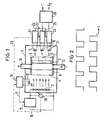
- Fig. 1 schematisch den prinzipiellen Aufbau einer Anordnung zur Bestimmung zweier Parameter,
- Fig. 2 den zeitlichen Verlauf der Einschaltzeiten der LED's und der Detektoren gemäss Fig.1,
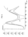
- Fig.3 ein Emissionsspektrum für eine lumineszierende Schicht und
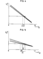
- Fig. 4,5 schematische Detektorsignalverläufe für zwei Wellenlängen in Abhängigkeit vom Sauerstoffpartialdruck und von der Temperatur.
- Fig. 1 shows schematically the basic structure of a Arrangement for determining two parameters,
- 2 shows the time course of the switch-on times of the LEDs and the detectors according to FIG. 1,
- 3 shows an emission spectrum for a luminescent layer and
- Fig. 4.5 schematic detector waveforms for two wavelengths depending on the oxygen partial pressure and the temperature.
Fig. 1 zeigt schematisch und teilweise im Schnitt eine Anordnung zur gleichzeitigen Bestimmung der Sauerstoffkonzentration und der Temperatur eines Gases. In einem lichtdichten Gehäuse 1 befinden sich eine Anzahl in Reihe geschalteter LED's 2, eine transparente lumineszierende Schicht 3 und Filter 4-7, die zusammen mit der Schicht in einem Halter 8 angeordnet sind, sowie vier Fotodioden 9-12. Das Gehäuse 1 und der Halter 8 sind mit einem Gaseinlass 13 und einem Gasauslass 14 versehen. Die Richtung des Gasstromes ist durch Pfeile angedeutet. Sie ist ohne Bedeutung für das Funktionieren der Anordnung. Das Gas wird auf diese Weise direkt an der Lumineszenzschicht vorbeigeleitet.In Fig.1 ist das nur prinzipiell und nicht massstäblich angedeutet. Damit der Parameter, der gemessen werden soll, schnell an der Schicht 3 variiert werden kann, sollten Gasein- bzw. Gasauslass gross und das Volumen zwischen Filter 4 und Schicht 3 dagegen klein sein.Fig. 1 shows schematically and partially in section an arrangement for the simultaneous determination of the oxygen concentration and the temperature of a gas. In a light-tight housing 1 there are a number of LEDs 2 connected in series, a transparent
Die LED's werden über eine Stromversorgung 15 gepulst betrieben. Im oberen Teil der Fig.2 ist der zeitliche Stromverlauf dargestellt, wenn mit konstantem Strom gepulst wird. Gestrichelt ist dabei der Teil der Impulse dargestellt,der variiert werden kann. Es ist im Bedarfsfall, wie bereits eingangs angegeben, auch möglich, andere Impulsformen zu wählen. Die Regelung erfolgt über die Stromversorgung 15 in Abhängigkeit von einem Diodenparameter. In der Fig 1 sind alternativ verschiedene Möglichkeiten angedeutet. So kann über den Detektor 12 die Intensität des ausgestrahlten Lichtes bestimmt und einer Servovorrichtung 16 zugeführt werden, die wiederum , wie durch den Pfeil 17 angedeutet, die Stromversorgung 15 ansteuert.The LEDs are operated in a pulsed manner via a
Eine weitere Möglichkeit besteht darin, den Spannungsabfall über den LED's mit einem Messinstrument 18 zu bestimmen und dieses Signal der Servovorrichtung zur Steuerung zuzuführen, wie gestrichelt durch die Leitung 19 angedeutet ist.Another possibility is to determine the voltage drop across the LEDs using a measuring
Eine dritte Möglichkeit besteht darin, die Intensität des durch die Lumineszenzschicht und ein an den Wellenlängenbereich des Anregungslichtes angepasstes Filter hindurchgehendes Licht mittels des Detektors 9 zu messen. und dieses Signal, wie durch die gestrichelte Leitung 20 angedeutet, wiederum der Servovorrichtung zuzuführen.A third possibility consists in measuring the intensity of the light passing through the luminescent layer and a filter adapted to the wavelength range of the excitation light by means of the
Unabhängig von der Art der Regelung kann damit erreicht werden, dass die spektrale Verteilung und die Intensität des emittierten Lichtes konstant bleiben oder zumindest einen definierten Verlauf haben.Regardless of the type of control, it can be achieved that the spectral distribution and the intensity of the emitted light remain constant or at least have a defined course.
6 und 7 sind zwei Filter für unterschiedliche Wellenlängenbereiche des Lumineszenzspektrums. Das durch diese Filter hindurchgehende Licht wird durch die Detektoren 10 bzw. 11 registriert.6 and 7 are two filters for different wavelength ranges of the luminescence spectrum. The light passing through these filters is registered by the
An die Detektoren 9-11 sind unmittelbar Verstärker 21-23 angeschlossen,die zusätzlich möglicherweise Integrations-, Differentier- und andere Glieder enthalten können. Sie bestimmen gleichzeitig die Impulsdauer für die Registrierung der von den Detektoren kommenden Signale, wie sie im unteren Teil der Fig 2 dargestellt ist.Amplifiers 21-23 are directly connected to the detectors 9-11, which may additionally contain integration, differentiation and other elements. At the same time, they determine the pulse duration for the registration of the signals coming from the detectors, as shown in the lower part of FIG. 2.
Wird mit dem Verstärker 21 das Signal des Detektors 9 bestimmt, so kann dieses über Leitungen 24,25 auf die Verstärker 22 bzw. 23 gegeben werden, in denen dann der auf die Intensität des Anregungslichtes normierte Signalwert der Detektoren 10 bzw 11 gebildet wird.If the signal from the
Wie im unteren Teil der Fig.2 dargestellt, ist die Impulsbreite für die Registrierung des Lumineszenzlichtes kleiner als die kleinste Impulsbreite des Anregungslichtes.As shown in the lower part of FIG. 2, the pulse width for the registration of the luminescent light is smaller than the smallest pulse width of the excitation light.
Die Ausgangssignale der beiden Verstärker 22 und 23 sind auf eine Signalbearbeitungseinrichtung 26 gegeben, die daraus die Werte für die Sauerstoffkonzentration und die Temperatur ermittelt.The output signals of the two
Zum besseren Verständnis ist in der folgenden Fig. 3 das Emissionsspektrum einer lumineszierenden Schicht und dessen Abhängigkeit von den Parametern Sauerstoff und Temperatur dargestellt.Im linken Bereich der Figur sind die Bedingungen für die verschiedenen Kurven angegeben . Das Lumineszenzspektrum weist zwei Emissionsmaxima auf, eins etwa bei 655 und das andere bei 720 nm. Das Anregungslicht hat eine kürzere Wellenlänge. Wie dieser Fig. zu entnehmen ist, tritt durch Sauerstoff eine starke Lumineszenzlöschung ein. Einen gleichgerichteten, jedoch schwächeren Effekt verursacht steigende Temperatur. Darüberhinaus tritt aber mit steigender Temperatur unabhängig von der Sauerstoffkonzentration noch eine Verschiebung der Lumineszenzmaxima zu höheren Wellenlängen hin auf. Da es bei der Respiratorbehandlung von Patienten in der ausgeatmeten Luft zu raschen Temperaturschwankungen über mehrere Grade Celsius kommen kann, war bisher die schnelle Sauerstoffkonzentrationsmessung, beispielsweise in der Exspirationsphase, nicht möglich.For a better understanding, the emission spectrum of a luminescent layer and its dependence on the parameters oxygen and temperature are shown in the following FIG. 3. The conditions for the different curves are indicated in the left area of the figure. The luminescence spectrum has two emission maxima, one at about 655 and the other at 720 nm. The excitation light has a shorter wavelength. As can be seen from this figure, strong luminescence quenching occurs due to oxygen. Rising temperature causes a rectified but weaker effect. Furthermore, with increasing temperature, the luminescence maxima shift to higher wavelengths regardless of the oxygen concentration. Since rapid respiratory fluctuations of several degrees Celsius can occur during the respiratory treatment of patients in the exhaled air, rapid oxygen concentration measurement, for example in the expiration phase, was previously not possible.
Das erfindungsgemässe Verfahren sieht nun vor, das Lumineszenzlicht in zwei Wellenlängenbereichen zu messen. In Fig.3 sind gestrichelt beispielsweise die obere Bandkante 61 des Filters 6 und die untere Bandkante 71 des Filters 7 angedeutet. Tritt nun z.B. eine Temperaturerhöhung auf, so wandert - anschaulich gesprochen - das erste Lumineszenzmaximum aus dem Transparenzbereich des Filters 6 heraus und das zweite Maximum in den Transparenzbereich des Filters 7 hinein. Wie diese Ueberlegungen zeigen, ergeben sich daher bei einer Temperaturänderung recht unterschiedliche Veränderungen der Signale der Detektoren 10 bzw.11. Gemäss der Formel für zwei Parameter, in diesem Falle die Sauerstoffkonzentration,die sich bei bekanntem Druck durch den Sauer- stoffpartialdruck P02 ausdrücken lässt,und die Temperatur T, ergibt sich folgendes Detektorsignal S1:
Entsprechendes gilt für das Detektorsignal S2. Wenn mit Hilfe verschiedener Kalibrierungen die Koeffizienten ermittelt sind, können aus diesen beiden Gleichungen die Werte für die beiden Parameter T und P02 in der Signalbearbeitungseinrichtung ermittelt werden. Dabei ist zu beachten, dass die Koeffizienten in der Formel für S2 andere Werte annehmen können als in der Formel für S1. Gewisse Koeffizienten müssen dabei durch Kalibrierungen festgelegt werden. Andere können stets feste Werte haben.The same applies to the detector signal S 2 . If the coefficients are determined with the aid of different calibrations, the values for the two parameters T and P 02 can be determined in the signal processing device from these two equations. It should be noted that the coefficients in the formula for S 2 can have different values than in the formula for S 1 . Certain coefficients have to be determined by calibrations. Others can always have fixed values.
Wie bereits erwähnt, können die beiden Parameter auch iterativ bestimmt werden. Das soll kurz anhand der Figuren 4 und 5 erläutert werden. In beiden Figuren ist der Verlauf der Messignale der Detektoren 10 bzw. 11 in Abhängigkeit vom Sauerstoffpartialdruck aufgetragen und der Einfachheit halber - da es nur um das Prinzip geht - ein linearer Zusammenhang angenommen. Die fünf Geraden in beiden Figuren gelten für fünf verschiedene Temperaturen zwischen 20 und 30 Grad Celsius. Mit steigender Temperatur nehmen die Detektorsignale ab.As already mentioned, the two parameters can also be determined iteratively. This will be briefly explained with reference to Figures 4 and 5. In both figures, the course of the measurement signals of the
Es sei nun angenommen,dass jeder Detektor ein Messignal liefert. Diesen entsprechen, wegen der unbestimmten Temperatur, auf den P02 -Achsen einA 1 bzw A 2 Bereich. Setzt man den kleineren Bereich, im vorliegenden Fall Δ1 1 in das Diagramm gemäss Fig.5 ein, so zeigt sich, dass dann nicht mehr alle Temperaturen zulässig sind. Mit anderen Worten, der mögliche Temperaturbereich wird verkleinert. Dadurch verkleinert sich nun wiederum gemäss Fig.4 der P02 Bereich, mit dem man dann wieder in Fig.5 die Temperatur weiter einschränkt u.s.w..Durch wiederholtes Anwenden dieses Verfahrens lassen sich also ebenfalls die beiden Parameter mit hinreichender Genauigkeit bestimmen.It is now assumed that each detector delivers a measurement signal. Because of the indefinite temperature, these correspond to an A 1 or A 2 range on the P 02 axes. If the smaller range, in the present case Δ1 1, is used in the diagram according to FIG. 5, it is evident that not all temperatures are then permissible. In other words, the possible temperature range is reduced. This now reduces again according to Fi g . 4 the P 02 range, with which the temperature is then again limited in FIG. 5, etc. By repeatedly using this method, the two parameters can also be determined with sufficient accuracy.
Welches Verfahren man jeweils wählen wird, hängt u.a. davon ab, ob sich für bestimmte Parameter, .insbesondere wenn es mehr als zwei sind, eine genügend exakte Formel aufstellen lässt und welchen Rechenaufwand man zulassen kann, um noch in wenigen ms die Parameterwerte zu erhalten.Which method you will choose depends on, among other things. depends on whether a sufficiently precise formula can be set up for certain parameters, especially if there are more than two, and what computing effort can be allowed to obtain the parameter values in just a few ms.
Misst bzw. bestimmt man neben der Sauerstoffkonzentration auch noch die Sauerstoffaufnahme,die C02- Konzentration, die C02-Produktion, den Druck,den Gasfluss und den respiratorischen Quotienten, so erhält man ein vollständiges Bild über die bei der Beatmung eines Patienten vorliegenden Verhältnisse.In addition to measuring the oxygen concentration, one also measures the oxygen uptake, the C0 2 concentration, the C0 2 production, the pressure, the gas flow and the respiratory quotient, so one obtains a complete picture of the conditions present when a patient is ventilated .
Das erfindungsgemässe Verfahren und die Anordnung zur Durchführung desselben kann vorteilhaft auch noch für andere Messungen ausgenutzt werden. Ist beispielweise der prozentuale Sauerstoffgehalt konstant - derartige Verhältnisse liegen in der Erdatmosphäre vor - so variiert die mit der Lumineszenzschicht in Berührung kommende Sauerstoffmenge mit dem Druck. Mit dem Verfahren können in diesem Fall neben der Temperatur der Gasdruck gemessen werden. Die Anordnung stellt daher auch ein ausgezeichnetes Barometer dar.The method according to the invention and the arrangement for carrying it out can advantageously also be used for other measurements. If, for example, the percentage oxygen content is constant - there are such conditions in the earth's atmosphere - the amount of oxygen coming into contact with the luminescent layer varies with the pressure. With the procedure In this case, the gas pressure can be measured in addition to the temperature. The arrangement is therefore an excellent barometer.
Wählt man eine Schicht, deren Lumineszenzeigenschaften von Feuchtigkeit abhängen, so kann man in entsprechender Weise ein sehr schnelles und exaktes Hygrometer erhalten.If you choose a layer whose luminescent properties depend on moisture, you can get a very fast and exact hygrometer in a corresponding way.
Durch Wahl der Anregungswellenlänge, der Filtercharakteristika und speziell der Schichteigenschaften lassen sich für alle Messungen gute Bedingungen schaffen.By choosing the excitation wavelength, the filter characteristics and especially the layer properties, good conditions can be created for all measurements.
Mit Hilfe von wasserunempfindlichen Schichten beispielsweise kann mittels eines kleinen Katheters der Blutsauerstoffgehalt schnell bestimmt werden. Integriert in eine Herzschrittmacherelektrode könnte somit ein physiologischer Steuerparameter gemessen werden.With the help of water-insensitive layers, for example, the blood oxygen content can be quickly determined using a small catheter. Integrated into a pacemaker electrode, a physiological control parameter could thus be measured.
Die Erfindung ist nicht auf die durch die Ausführungsbeispiele angegebenen Verfahren und Anordnungen beschränkt, sondern kann mit Hilfe normalen fachmännischen Könnens in weiten Bereichen variiert werden, ohne den durch die Ansprüche festgelegten Rahmen zu verlassen.So besteht z.B. die Möglichkeit, Lumineszenzschichten zu verwenden, die aus mehreren Kombinationen Farbstoff/Trägermaterial bestehen, wobei jede Kombination auf einen oder einige der interessierenden Parameter reagiert. Die unterschiedlichen Kombinationen können dabei in der Lumineszenzschicht getrennt liegen. Die Anregung kann über eine gemeinsame Lichtquelle oder über veschiedene erfolgen.The invention is not limited to the methods and arrangements specified by the exemplary embodiments, but can be varied within a wide range with the aid of normal, professional skill without leaving the scope defined by the claims. the possibility of using luminescent layers which consist of several combinations of dye / carrier material, each combination reacting to one or some of the parameters of interest. The different combinations can lie separately in the luminescent layer. The excitation can take place via a common light source or via different ones.
Claims (18)

verhalten, wobei ii die Lumineszenzintensität im Wellenlängenbereich λi und bei einem bestimmten Wert des Parameters X1, insbesondere X1=0, ai eine Untergrundintensität und ki und bi Näherungskoeffizienten sind.6. The method according to any one of claims 1 to 5, characterized in that when two parameters X 1 and X 2 influencing the luminescence properties are present, the detector signals (S i , i = 1,2) are determined according to the formula
behave, where i i is the luminescence intensity in the wavelength range λ i and at a certain value of the parameter X 1 , in particular X 1 = 0, a i is a background intensity and ki and bi are approximation coefficients.
Applications Claiming Priority (2)
| Application Number | Priority Date | Filing Date | Title |
|---|---|---|---|
| DE3434423 | 1984-09-19 | ||
| DE3434423 | 1984-09-19 |
Publications (3)
| Publication Number | Publication Date |
|---|---|
| EP0175352A2 true EP0175352A2 (en) | 1986-03-26 |
| EP0175352A3 EP0175352A3 (en) | 1988-09-07 |
| EP0175352B1 EP0175352B1 (en) | 1991-06-12 |
Family
ID=6245822
Family Applications (1)
| Application Number | Title | Priority Date | Filing Date |
|---|---|---|---|
| EP85111761A Expired - Lifetime EP0175352B1 (en) | 1984-09-19 | 1985-09-17 | Method and device for rapidly ascertaining the parameters of a sample medium |
Country Status (7)
| Country | Link |
|---|---|
| US (1) | US4968632A (en) |
| EP (1) | EP0175352B1 (en) |
| JP (1) | JPH0697205B2 (en) |
| AU (1) | AU574839B2 (en) |
| CA (1) | CA1266996A (en) |
| DE (1) | DE3583197D1 (en) |
| ES (1) | ES8706959A1 (en) |
Cited By (6)
| Publication number | Priority date | Publication date | Assignee | Title |
|---|---|---|---|---|
| EP0357586A2 (en) * | 1988-08-02 | 1990-03-07 | AVL Medical Instruments AG | Process for the quantitative determination of at least one parameter of a liquid or gaseous sample |
| DE4239016A1 (en) * | 1991-11-20 | 1993-05-27 | Hamamatsu Photonics Kk | |
| EP0675348A1 (en) * | 1994-03-30 | 1995-10-04 | Societe Europeenne De Propulsion | Device for optical measurement of cryogenic temperatures |
| EP1562037A1 (en) * | 2002-11-14 | 2005-08-10 | ARKRAY, Inc. | Measuring instrument and fluorometric method |
| WO2010081790A1 (en) * | 2009-01-19 | 2010-07-22 | Smart Medical Solutions Gmbh | Measuring arrangement for determining at least one parameter of a blood sample |
| WO2020027716A1 (en) * | 2018-08-03 | 2020-02-06 | Redsense Medical Ab | Device for measuring a property of a measurement object by luminescence |
Families Citing this family (20)
| Publication number | Priority date | Publication date | Assignee | Title |
|---|---|---|---|---|
| US5094959A (en) * | 1989-04-26 | 1992-03-10 | Foxs Labs | Method and material for measurement of oxygen concentration |
| AT403745B (en) * | 1996-02-29 | 1998-05-25 | Avl Verbrennungskraft Messtech | MEASURING ARRANGEMENT WITH A TRANSPARENT ELEMENT FOR EXCITING AND MEASURING RADIATION |
| US6815211B1 (en) | 1998-08-04 | 2004-11-09 | Ntc Technology | Oxygen monitoring methods and apparatus (I) |
| US7335164B2 (en) | 1996-07-15 | 2008-02-26 | Ntc Technology, Inc. | Multiple function airway adapter |
| US6325978B1 (en) | 1998-08-04 | 2001-12-04 | Ntc Technology Inc. | Oxygen monitoring and apparatus |
| GB9717021D0 (en) * | 1997-08-12 | 1997-10-15 | Kalibrant Limited | A detector |
| US6391264B2 (en) * | 1999-02-11 | 2002-05-21 | Careside, Inc. | Cartridge-based analytical instrument with rotor balance and cartridge lock/eject system |
| US6531095B2 (en) * | 1999-02-11 | 2003-03-11 | Careside, Inc. | Cartridge-based analytical instrument with optical detector |
| US6632402B2 (en) | 2001-01-24 | 2003-10-14 | Ntc Technology Inc. | Oxygen monitoring apparatus |
| AUPS267702A0 (en) * | 2002-05-30 | 2002-06-20 | Corbett Research Pty Ltd | Optical means for calibrating temperature |
| US20060171845A1 (en) * | 2005-01-31 | 2006-08-03 | Dakota Technologies, Inc. | Sensors for measuring analytes |
| JP2008545968A (en) * | 2005-06-02 | 2008-12-18 | グラクソ グループ リミテッド | Inductive drive type remote oxygen sensor |
| US9518955B2 (en) * | 2005-12-12 | 2016-12-13 | Advanced Analytical Technologies, Inc. | Capillary electrophoresis fluorescent detection system |
| US7781221B2 (en) * | 2006-08-18 | 2010-08-24 | Ric Investments, Llc | System and method of compensating for system delay in analyte analyzation |
| EP2150176B1 (en) * | 2007-04-27 | 2016-04-27 | St. Jude Medical AB | Implantable concentration sensor and device |
| US20090128344A1 (en) * | 2007-11-21 | 2009-05-21 | General Electric Company | Systems, Apparatuses And Methods For Monitoring Physical Conditions Of A Bed Occupant |
| JP4631922B2 (en) * | 2008-03-31 | 2011-02-16 | トヨタ自動車株式会社 | Sample concentration detection method, apparatus and program |
| JP4725593B2 (en) * | 2008-03-31 | 2011-07-13 | トヨタ自動車株式会社 | Sample concentration detection method, apparatus and program |
| JP5301254B2 (en) * | 2008-12-02 | 2013-09-25 | 理研計器株式会社 | Optical gas detector |
| JP6264912B2 (en) * | 2014-02-04 | 2018-01-24 | 学校法人慶應義塾 | Temperature and oxygen concentration measuring device |
Citations (4)
| Publication number | Priority date | Publication date | Assignee | Title |
|---|---|---|---|---|
| US3910701A (en) * | 1973-07-30 | 1975-10-07 | George R Henderson | Method and apparatus for measuring light reflectance absorption and or transmission |
| US4003707A (en) * | 1975-02-28 | 1977-01-18 | Max-Planck-Gesellschaft Zur Forderung Der Wissenschaften E.V. | Method and arrangement for measuring the concentration of gases |
| US4167331A (en) * | 1976-12-20 | 1979-09-11 | Hewlett-Packard Company | Multi-wavelength incremental absorbence oximeter |
| EP0091390A1 (en) * | 1982-03-30 | 1983-10-12 | THE UNITED STATES OF AMERICA as represented by the Secretary United States Department of Commerce | Fiber optic PO2 probe |
Family Cites Families (12)
| Publication number | Priority date | Publication date | Assignee | Title |
|---|---|---|---|---|
| US3285703A (en) * | 1963-05-31 | 1966-11-15 | Nippon Oxygen Co Ltd | Photosensitive means for determining trace oxygen by measuring chemiluminescence |
| US3612866A (en) * | 1969-07-08 | 1971-10-12 | Brian Stevens | Instrument for determining oxygen quantities by measuring oxygen quenching of fluorescent radiation |
| US3725658A (en) * | 1971-01-18 | 1973-04-03 | Trw Inc | Apparatus and method for continuously detecting oxygen in a gas stream |
| JPS5036191A (en) * | 1973-07-25 | 1975-04-05 | ||
| CA1049808A (en) * | 1975-02-10 | 1979-03-06 | Arthur Fontijn | Chemiluminescent method and apparatus for determining the photochemical reactivity of organic pollutants |
| JPS51103495A (en) * | 1975-03-10 | 1976-09-13 | Kogyo Gijutsuin | KITAIKAGAKUHATSUKOHONYORU FUKUSUSEIBUNNO NODOSOKUTEIHOHO |
| US4150951A (en) * | 1977-09-19 | 1979-04-24 | The Aerospace Corporation | Measurement of concentrations of gaseous phase elements |
| DE3148830A1 (en) * | 1981-12-10 | 1983-06-23 | Wolfgang Prof. Dr.Dr. 6500 Mainz Barnikol | "DEVICE FOR DETERMINING THE OXYGEN CONCENTRATION IN GASES, LIQUIDS AND TISSUES" |
| US4495293A (en) * | 1983-02-24 | 1985-01-22 | Abbott Laboratories | Fluorometric assay |
| AT390840B (en) * | 1983-06-08 | 1990-07-10 | Avl Verbrennungskraft Messtech | METHOD FOR FLUORIMETRICALLY DETERMINING THE CONCENTRATION OF SUBSTANCES CONTAINING A SUBSTANCE AND ARRANGEMENT FOR CARRYING OUT THIS METHOD |
| EP0190830A3 (en) * | 1985-02-04 | 1988-04-27 | Gould Inc. | Single optical fiber sensor for measuring the partial pressure of oxygen |
| US4752115A (en) * | 1985-02-07 | 1988-06-21 | Spectramed, Inc. | Optical sensor for monitoring the partial pressure of oxygen |
-
1985
- 1985-09-17 EP EP85111761A patent/EP0175352B1/en not_active Expired - Lifetime
- 1985-09-17 JP JP60205152A patent/JPH0697205B2/en not_active Expired - Lifetime
- 1985-09-17 DE DE8585111761T patent/DE3583197D1/en not_active Expired - Fee Related
- 1985-09-17 CA CA000490875A patent/CA1266996A/en not_active Expired - Fee Related
- 1985-09-18 AU AU47573/85A patent/AU574839B2/en not_active Ceased
- 1985-09-19 ES ES547133A patent/ES8706959A1/en not_active Expired
-
1989
- 1989-09-18 US US07/409,964 patent/US4968632A/en not_active Expired - Fee Related
Patent Citations (4)
| Publication number | Priority date | Publication date | Assignee | Title |
|---|---|---|---|---|
| US3910701A (en) * | 1973-07-30 | 1975-10-07 | George R Henderson | Method and apparatus for measuring light reflectance absorption and or transmission |
| US4003707A (en) * | 1975-02-28 | 1977-01-18 | Max-Planck-Gesellschaft Zur Forderung Der Wissenschaften E.V. | Method and arrangement for measuring the concentration of gases |
| US4167331A (en) * | 1976-12-20 | 1979-09-11 | Hewlett-Packard Company | Multi-wavelength incremental absorbence oximeter |
| EP0091390A1 (en) * | 1982-03-30 | 1983-10-12 | THE UNITED STATES OF AMERICA as represented by the Secretary United States Department of Commerce | Fiber optic PO2 probe |
Non-Patent Citations (1)
| Title |
|---|
| ADVANCES IN INSTRUMENTATION, Band 38, Oktober 1983, Seiten 925-932, ISA, Chicago, US; R.V. ALVES et al.: "Temperature sensing using optical fibers" * |
Cited By (16)
| Publication number | Priority date | Publication date | Assignee | Title |
|---|---|---|---|---|
| EP0357586A2 (en) * | 1988-08-02 | 1990-03-07 | AVL Medical Instruments AG | Process for the quantitative determination of at least one parameter of a liquid or gaseous sample |
| EP0357586A3 (en) * | 1988-08-02 | 1991-01-09 | AVL Medical Instruments AG | Process for the quantitative determination of at least one parameter of a liquid or gaseous sample |
| DE4239016A1 (en) * | 1991-11-20 | 1993-05-27 | Hamamatsu Photonics Kk | |
| EP0675348A1 (en) * | 1994-03-30 | 1995-10-04 | Societe Europeenne De Propulsion | Device for optical measurement of cryogenic temperatures |
| FR2718237A1 (en) * | 1994-03-30 | 1995-10-06 | Europ Propulsion | Optical cryogenic temperature measurement device. |
| US5980105A (en) * | 1994-03-30 | 1999-11-09 | Societe Europeenne De Propulsion | Device of optically measuring a cryogenic temperature |
| US6017148A (en) * | 1994-03-30 | 2000-01-25 | Societe National D'etude Et De Construction De Moteurs D'aviation | Device for optically measuring a cryogenic temperature |
| US6086250A (en) * | 1994-03-30 | 2000-07-11 | Societe Nationale D'etude Et De Construction De Moteurs D'aviation | Device for optically measuring a cryogenic temperature |
| EP1562037A1 (en) * | 2002-11-14 | 2005-08-10 | ARKRAY, Inc. | Measuring instrument and fluorometric method |
| EP1562037B1 (en) * | 2002-11-14 | 2012-01-11 | ARKRAY, Inc. | Measuring instrument and fluorometric method |
| WO2010081790A1 (en) * | 2009-01-19 | 2010-07-22 | Smart Medical Solutions Gmbh | Measuring arrangement for determining at least one parameter of a blood sample |
| RU2468355C1 (en) * | 2009-01-19 | 2012-11-27 | Смарт Медикал Солюшнз Гмбх | Measuring device for determining at least one blood sample parameter |
| AU2010205741B2 (en) * | 2009-01-19 | 2013-04-18 | Smart Medical Solutions Gmbh | Measuring arrangement for determining at least one parameter of a blood sample |
| US8698103B2 (en) | 2009-01-19 | 2014-04-15 | Smart Medical Solutions Gmbh | Measuring device for determination of at least one parameter of a blood sample |
| WO2020027716A1 (en) * | 2018-08-03 | 2020-02-06 | Redsense Medical Ab | Device for measuring a property of a measurement object by luminescence |
| US11604142B2 (en) | 2018-08-03 | 2023-03-14 | Odinwell Ab | Device for measuring a property of a measurement object by luminescence |
Also Published As
| Publication number | Publication date |
|---|---|
| ES8706959A1 (en) | 1987-07-01 |
| JPS6179143A (en) | 1986-04-22 |
| AU4757385A (en) | 1986-03-27 |
| JPH0697205B2 (en) | 1994-11-30 |
| US4968632A (en) | 1990-11-06 |
| EP0175352A3 (en) | 1988-09-07 |
| EP0175352B1 (en) | 1991-06-12 |
| DE3583197D1 (en) | 1991-07-18 |
| CA1266996A (en) | 1990-03-27 |
| AU574839B2 (en) | 1988-07-14 |
| ES547133A0 (en) | 1987-07-01 |
Similar Documents
| Publication | Publication Date | Title |
|---|---|---|
| EP0175352B1 (en) | Method and device for rapidly ascertaining the parameters of a sample medium | |
| DE2049716C3 (en) | Method and device for measuring absorption in blood | |
| DE10213692B4 (en) | Method for controlling a device and device for measuring ingredients in the blood | |
| DE69727776T2 (en) | METHOD FOR DETERMINING THE FRACTIONAL OXYGEN SATURATION | |
| DE2165106C2 (en) | Method and device for the analysis of atomic spectra | |
| DE2428884A1 (en) | ABSORPTION SPECTROGRAPHIC ANALYSIS PROCEDURE AND EQUIPMENT FOR ITS PERFORMANCE | |
| EP2135059A2 (en) | Measuring device and method for optically determining the concentration of blood sugar and/or lactate in biological systems | |
| DE102010034626A1 (en) | Device for extracorporeal blood treatment | |
| EP0135101B1 (en) | Fluorometer | |
| CH627277A5 (en) | ||
| DE2756462A1 (en) | CIRCUIT ARRANGEMENT FOR SELECTIVE MEASUREMENT OF THE CONCENTRATION OF A SUBSTANCE | |
| DE102009055320A1 (en) | Measuring device and method for examining a sample gas by means of infrared absorption spectroscopy | |
| DE2543124A1 (en) | METHOD OF DISTINCTION BETWEEN DISCRETE PARTICLES AND DEVICE FOR CARRYING OUT THE METHOD | |
| DE2511771B2 (en) | ARRANGEMENT FOR DETERMINING THE ALCOHOL CONTENT IN THE BLOOD | |
| DE2927156A1 (en) | DEVICE FOR MEASURING THE OXYGEN CONCENTRATION | |
| EP0037151B1 (en) | Computed tomographic apparatus | |
| DE112017005214T5 (en) | endoscopy system | |
| DE4325529C2 (en) | Device for determining the concentration of substances in the blood | |
| DE19628310C2 (en) | Optical gas analyzer | |
| WO1995013739A1 (en) | Method and device for the non-invasive transcutanean determination of the concentrations of substances in human body fluids or tissues | |
| EP0548027B1 (en) | Apparatus for spectro photometric analysis | |
| WO2014139830A1 (en) | Method and device for monitoring vital functions | |
| DE2412265A1 (en) | PROCEDURE AND ARRANGEMENT FOR DETERMINING THE INTENSITY MAXIMA AND THE WAVELENGTHS ASSIGNED TO THEM AS A FUNCTION OF THE LOCATION | |
| DE102013101523A1 (en) | A photometric measuring apparatus and method for measuring an optical absorbance of a fluid having a variable concentration of at least one light-absorbing substance, and a blood processing apparatus having such a measuring apparatus | |
| DE2127994C3 (en) | Analyzer |
Legal Events
| Date | Code | Title | Description |
|---|---|---|---|
| PUAI | Public reference made under article 153(3) epc to a published international application that has entered the european phase |
Free format text: ORIGINAL CODE: 0009012 |
|
| AK | Designated contracting states |
Kind code of ref document: A2 Designated state(s): CH DE FR GB IT LI NL SE |
|
| PUAL | Search report despatched |
Free format text: ORIGINAL CODE: 0009013 |
|
| AK | Designated contracting states |
Kind code of ref document: A3 Designated state(s): CH DE FR GB IT LI NL SE |
|
| 17P | Request for examination filed |
Effective date: 19881108 |
|
| 17Q | First examination report despatched |
Effective date: 19900316 |
|
| GRAA | (expected) grant |
Free format text: ORIGINAL CODE: 0009210 |
|
| AK | Designated contracting states |
Kind code of ref document: B1 Designated state(s): CH DE FR GB IT LI NL SE |
|
| REF | Corresponds to: |
Ref document number: 3583197 Country of ref document: DE Date of ref document: 19910718 |
|
| ET | Fr: translation filed | ||
| ITF | It: translation for a ep patent filed |
Owner name: STUDIO JAUMANN |
|
| GBT | Gb: translation of ep patent filed (gb section 77(6)(a)/1977) | ||
| PLBE | No opposition filed within time limit |
Free format text: ORIGINAL CODE: 0009261 |
|
| STAA | Information on the status of an ep patent application or granted ep patent |
Free format text: STATUS: NO OPPOSITION FILED WITHIN TIME LIMIT |
|
| 26N | No opposition filed | ||
| EAL | Se: european patent in force in sweden |
Ref document number: 85111761.4 |
|
| PGFP | Annual fee paid to national office [announced via postgrant information from national office to epo] |
Ref country code: GB Payment date: 19960821 Year of fee payment: 12 |
|
| PGFP | Annual fee paid to national office [announced via postgrant information from national office to epo] |
Ref country code: NL Payment date: 19960916 Year of fee payment: 12 |
|
| PGFP | Annual fee paid to national office [announced via postgrant information from national office to epo] |
Ref country code: SE Payment date: 19970911 Year of fee payment: 13 |
|
| PG25 | Lapsed in a contracting state [announced via postgrant information from national office to epo] |
Ref country code: GB Free format text: LAPSE BECAUSE OF NON-PAYMENT OF DUE FEES Effective date: 19970917 |
|
| PGFP | Annual fee paid to national office [announced via postgrant information from national office to epo] |
Ref country code: FR Payment date: 19970924 Year of fee payment: 13 |
|
| PGFP | Annual fee paid to national office [announced via postgrant information from national office to epo] |
Ref country code: CH Payment date: 19971217 Year of fee payment: 13 |
|
| PG25 | Lapsed in a contracting state [announced via postgrant information from national office to epo] |
Ref country code: NL Free format text: LAPSE BECAUSE OF NON-PAYMENT OF DUE FEES Effective date: 19980401 |
|
| GBPC | Gb: european patent ceased through non-payment of renewal fee |
Effective date: 19970917 |
|
| NLV4 | Nl: lapsed or anulled due to non-payment of the annual fee |
Effective date: 19980401 |
|
| PG25 | Lapsed in a contracting state [announced via postgrant information from national office to epo] |
Ref country code: SE Free format text: LAPSE BECAUSE OF NON-PAYMENT OF DUE FEES Effective date: 19980918 |
|
| PG25 | Lapsed in a contracting state [announced via postgrant information from national office to epo] |
Ref country code: LI Free format text: LAPSE BECAUSE OF NON-PAYMENT OF DUE FEES Effective date: 19980930 Ref country code: CH Free format text: LAPSE BECAUSE OF NON-PAYMENT OF DUE FEES Effective date: 19980930 |
|
| PGFP | Annual fee paid to national office [announced via postgrant information from national office to epo] |
Ref country code: DE Payment date: 19981117 Year of fee payment: 14 |
|
| REG | Reference to a national code |
Ref country code: CH Ref legal event code: PL |
|
| EUG | Se: european patent has lapsed |
Ref document number: 85111761.4 |
|
| PG25 | Lapsed in a contracting state [announced via postgrant information from national office to epo] |
Ref country code: FR Free format text: LAPSE BECAUSE OF NON-PAYMENT OF DUE FEES Effective date: 19990531 |
|
| REG | Reference to a national code |
Ref country code: FR Ref legal event code: ST |
|
| PG25 | Lapsed in a contracting state [announced via postgrant information from national office to epo] |
Ref country code: DE Free format text: LAPSE BECAUSE OF NON-PAYMENT OF DUE FEES Effective date: 20000701 |