EP0169727A2 - Broadband radial vibrator transducer - Google Patents
Broadband radial vibrator transducer Download PDFInfo
- Publication number
- EP0169727A2 EP0169727A2 EP85305220A EP85305220A EP0169727A2 EP 0169727 A2 EP0169727 A2 EP 0169727A2 EP 85305220 A EP85305220 A EP 85305220A EP 85305220 A EP85305220 A EP 85305220A EP 0169727 A2 EP0169727 A2 EP 0169727A2
- Authority
- EP
- European Patent Office
- Prior art keywords
- transducer
- resonant
- recited
- radial
- compliant
- Prior art date
- Legal status (The legal status is an assumption and is not a legal conclusion. Google has not performed a legal analysis and makes no representation as to the accuracy of the status listed.)
- Granted
Links
- 239000004033 plastic Substances 0.000 claims description 7
- 229920003023 plastic Polymers 0.000 claims description 7
- 238000006243 chemical reaction Methods 0.000 claims 1
- 230000004044 response Effects 0.000 description 23
- 239000000463 material Substances 0.000 description 12
- 239000011149 active material Substances 0.000 description 9
- 239000002131 composite material Substances 0.000 description 9
- 238000000034 method Methods 0.000 description 9
- 230000008901 benefit Effects 0.000 description 4
- 239000007788 liquid Substances 0.000 description 4
- 238000010276 construction Methods 0.000 description 3
- 239000007787 solid Substances 0.000 description 3
- 239000000126 substance Substances 0.000 description 3
- 239000004593 Epoxy Substances 0.000 description 2
- 229910000831 Steel Inorganic materials 0.000 description 2
- 239000003990 capacitor Substances 0.000 description 2
- 238000007906 compression Methods 0.000 description 2
- 230000006835 compression Effects 0.000 description 2
- 238000009472 formulation Methods 0.000 description 2
- 230000006872 improvement Effects 0.000 description 2
- 229910052451 lead zirconate titanate Inorganic materials 0.000 description 2
- HFGPZNIAWCZYJU-UHFFFAOYSA-N lead zirconate titanate Chemical compound [O-2].[O-2].[O-2].[O-2].[O-2].[Ti+4].[Zr+4].[Pb+2] HFGPZNIAWCZYJU-UHFFFAOYSA-N 0.000 description 2
- 239000000203 mixture Substances 0.000 description 2
- 230000004048 modification Effects 0.000 description 2
- 238000012986 modification Methods 0.000 description 2
- 239000010959 steel Substances 0.000 description 2
- 230000009466 transformation Effects 0.000 description 2
- OKTJSMMVPCPJKN-UHFFFAOYSA-N Carbon Chemical compound [C] OKTJSMMVPCPJKN-UHFFFAOYSA-N 0.000 description 1
- 239000004962 Polyamide-imide Substances 0.000 description 1
- 239000004642 Polyimide Substances 0.000 description 1
- 239000004963 Torlon Substances 0.000 description 1
- 229920003997 Torlon® Polymers 0.000 description 1
- 229910052782 aluminium Inorganic materials 0.000 description 1
- XAGFODPZIPBFFR-UHFFFAOYSA-N aluminium Chemical compound [Al] XAGFODPZIPBFFR-UHFFFAOYSA-N 0.000 description 1
- 238000004458 analytical method Methods 0.000 description 1
- 238000003491 array Methods 0.000 description 1
- 238000005452 bending Methods 0.000 description 1
- 239000000919 ceramic Substances 0.000 description 1
- 229910010293 ceramic material Inorganic materials 0.000 description 1
- 238000004590 computer program Methods 0.000 description 1
- 238000005094 computer simulation Methods 0.000 description 1
- 230000008602 contraction Effects 0.000 description 1
- 230000008878 coupling Effects 0.000 description 1
- 238000010168 coupling process Methods 0.000 description 1
- 238000005859 coupling reaction Methods 0.000 description 1
- 230000003247 decreasing effect Effects 0.000 description 1
- 230000000694 effects Effects 0.000 description 1
- 229910002804 graphite Inorganic materials 0.000 description 1
- 239000010439 graphite Substances 0.000 description 1
- 230000002706 hydrostatic effect Effects 0.000 description 1
- 238000002955 isolation Methods 0.000 description 1
- 239000011156 metal matrix composite Substances 0.000 description 1
- 230000010287 polarization Effects 0.000 description 1
- 229920003223 poly(pyromellitimide-1,4-diphenyl ether) Polymers 0.000 description 1
- 229920002312 polyamide-imide Polymers 0.000 description 1
- 229920001721 polyimide Polymers 0.000 description 1
- 230000005855 radiation Effects 0.000 description 1
- 230000029058 respiratory gaseous exchange Effects 0.000 description 1
- 230000035945 sensitivity Effects 0.000 description 1
- 238000000926 separation method Methods 0.000 description 1
Images

Classifications
-
- B—PERFORMING OPERATIONS; TRANSPORTING
- B06—GENERATING OR TRANSMITTING MECHANICAL VIBRATIONS IN GENERAL
- B06B—METHODS OR APPARATUS FOR GENERATING OR TRANSMITTING MECHANICAL VIBRATIONS OF INFRASONIC, SONIC, OR ULTRASONIC FREQUENCY, e.g. FOR PERFORMING MECHANICAL WORK IN GENERAL
- B06B1/00—Methods or apparatus for generating mechanical vibrations of infrasonic, sonic, or ultrasonic frequency
- B06B1/02—Methods or apparatus for generating mechanical vibrations of infrasonic, sonic, or ultrasonic frequency making use of electrical energy
- B06B1/06—Methods or apparatus for generating mechanical vibrations of infrasonic, sonic, or ultrasonic frequency making use of electrical energy operating with piezoelectric effect or with electrostriction
- B06B1/0644—Methods or apparatus for generating mechanical vibrations of infrasonic, sonic, or ultrasonic frequency making use of electrical energy operating with piezoelectric effect or with electrostriction using a single piezoelectric element
- B06B1/0655—Methods or apparatus for generating mechanical vibrations of infrasonic, sonic, or ultrasonic frequency making use of electrical energy operating with piezoelectric effect or with electrostriction using a single piezoelectric element of cylindrical shape
Definitions
- This invention relates to an electromechanical transducer and, more particularly, to a transducer commonly known as a radial vibrator transducer in which the dominant mechanical motion is in the radial direction of a cylindrical or spherical shaped transducer and which results in an alternate expansion and contraction of the transducer.
- a device commonly known as a "radial vibrator” is a simple and widely used electromechanical or electroacoustical transducer type.
- Such a device in its simplest form consists of a cylindrical or spherical piece of active material which can be driven electrically to induce a radial expansion therein.
- a tube or ring of a piezoelectric ceramic such as a lead zirconate titanate formulation
- This type of device is usually operated at its first circumferential or "breathing mode" resonance frequency to achieve a higher output.
- the frequency of this resonance is predominately determined by the type of material and the diameter of the ring or tube.
- a number of design schemes are commonly applied which fabricate the ring as a composite structure of alternating segments of active and inactive material. These methods are often implemented by joining bars of the different materials together as barrel staves to form a composite ring.
- the inactive material generally functions as an added mass and/or an added compliance which acts to lower the radial resonance frequency.
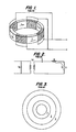
- An example of a prior art segmented ring radial vibrator is shown in Fig. 1.
- Piezoelectric material or active staves 1 are bonded to inactive staves 2 forming a composite cylinder and the active staves are electrically wired in parallel so that when a voltage is applied between the electrical leads, the composite cylinder expands or contracts along the radial axis of the device.
- the arrows on Fig. 1 indicate the direction of polarization and, as illustrated, the electrodes in this structure located at the boundaries between the active 1 and inactive 2 materials.
- the device of Fig. 1 may be used as either a generator or receiver of mechanical or acoustic energy and is normally operated in a frequency band approximately centered on its primary mechanical resonance frequency.
- Fig. 1 It is well known by those of ordinary skill in the art that the performance of the conventional transducer in Fig. 1 can be approximated by the analogous behavior of a simplified electrical equivalent circuit, as shown in Fig. 2. This approximation applies equally as well to a solid ring or a segmented ring as in Fig. 1.
- M represents the total mass of the ring
- C represents the clamped capacitance of the ring
- ⁇ represents the electromechanical transformation ratio of the active material.
- the resistor R at the right of the equivalent circuit represents the electric equivalent of the radiation resistance of the medium and the equivalent current u in the resistance R represents the velocity of the moving face of the radiator.
- the transmitting voltage response (TVR) of this prior art device is calculated from this equivalent circuit approximation and is proportional to the current u divided by the drive voltage E at the input to the transducer circuit.
- the radiator impedance can be neglected.
- the transmitting voltage response has a single peak near the frequency where the denominator of the expression becomes zero. This occurs at the resonance (angular) frequency r as set forth in Equation 2 below:
- a significant drawback of the prior art transducer of Fig. 1 is that the resonance frequency and operating bandwidth of the transducer cannot be independently controlled in a given size device.
- the low mechanical input impedance of this transducer at the radiating face also causes problems when the transducer is used in an array configuration where the input impedance of the radiating face needs to be high.
- the mechanical input impedance of the array elements must be maintained higher than the acoustic mutual impedances of the array for all possible operating frequencies, thereby precluding operation in a narrow band near the peak of the transducer response where the mechanical impedance becomes small.
- the basic device, as shown in Fig. 1, also has significant practical limits on the achievable bandwidth.
- the operating bandwidth can be changed by decreasing or increasing the thickness of the ring of the active material 1, or by changing the compliance of the inactive staves 2.
- this design technique is limited by the following practical design considerations. As the active material becomes thinner, to increase the operating frequency bandwidth, the device becomes mechanically fragile, a significant drawback in transducers intended for underwater use which must withstand the effects of hydrostatic pressure. Furthermore, if inactive material staves are included to decrease the resonance frequency, the sensitivity and power handling capability of the device will be reduced, which is a significant drawback in applications requiring high acoustic output levels.
- FIG. 3 Another well known technique for broadening the operating band of a transducer is to use external matching layers.
- the acoustic impedances of the transducer and the medium are matched through external matching layers as illustrated in Fig. 3.
- the internal active ring 1 is completely surrounded by a matching layer 3 consisting of a liquid which is preferably the same liquid as the medium.
- the liquid layer is surrounded by a solid ring 4 of a substance such as steel.
- This method will increase the bandwidth somewhat, as illustrated by curve 21 in Fig. 7, however, the requirement that the layers must conform to the surface and completely cover the device places a significant restriction on the range of operating frequency bands in which this technique can be used. In some application, the use of a liquid matching layer is undesirable.
- a compliant solid such as plastic
- the shape of the response curve is a fairly sensitive function of the density and speed of sound in the matching layer material making acceptable materials difficult to find.
- at least two frequencies occur in the operating band where the head mechanical input impedance becomes unacceptably low for operation in an array configuration. This reduces the usable bandwidth by at least 20 percent.
- the present invention achieves the above objects by providing a number of mechanically resonant composite structures between the outside surface of the active ring or sphere and the radiating medium.
- the mechanical resonators may be of identical construction and materials or may be different in dimensions and materials.
- Each composite resonator comprises a compliant layer and a mass layer.
- the active material ring and the mass layer are separated from each other by the compliant member.
- the compliant member allows the transducer to vibrate at two resonance frequencies which can be approximated as the resonant frequency of the mass loaded ring if the compliant member were eliminated and the resonant frequency if the mechanical resonator were mounted on a rigid structure.
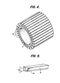
- the present invention achieves broadband operating frequency characteristics by mounting mechanically resonant sections 10, each having a laminar structure, on the outside of the active ring 1 as illustrated in Fig. 4.
- the composite sections 10 are mounted in a barrel stave type arrangement where the separation between staves is minimal.
- Fig. 5 illustrates a single stave 10 of the present invention where the resonating mass 11 is made from a material strong enough to avoid bending resonance, such as aluminum, steel, a metal matrix composite or a graphite epoxy.
- a compliant member 12 is interposed between the mass 11 and the active material 1.
- the compliant member can be a plastic, such as VESPEL, which is polyimide plastic sold by DuPont or TORLON a polyamide-imide plastic sold by Amoco Chemical Corporation or any other substance which provides the desired compliance.
- the active transducer element 1 can be a piezoelectric element manufactured from a piezoelectric ceramic material, such as a lead zirconate titanate formulation and can be obtained from Vernitron, Inc. in Bedford, Ohio.
- the side 13 of each stave should be slightly tapered to fit along side the other staves and the inner face 14 of the compliant member 12 should be slightly curved to fit the curved surface of the active ring 1.
- the electrodes (not shown) of the transducer are mounted on the inside and outside surface of the active material and polarized in the radial direction in a known manner.
- the entire transducer can be assembled either by using epoxy or loosely assembled and held together by a compression band.
- the adjustment of the compressive bias using the compression band is within the ordinary skill in the art.
- Equation 3 An approximate equivalent electrical circuit for the transducer of Fig. 4 is illustrated in Fig. 6.
- M 1 is the mass of the resonant mass 11 in contact with the medium.
- M is the mass of the active ring 1.
- C o represents the clamped electrical capacitance of the active material 1
- C represents the compliance of the active ring 1
- C 1 represents the compliance of the compliant member 12 separating the active ring 1 and the mass 11.
- ⁇ represents the electromechanical transformation ratio of the active material.
- Equation 3 sets forth the response of a doubly resonant system and the expression in the denominator can be solved to produce the approximate resonant frequencies as was performed on Equation 1 to obtain Equation 2, previously discussed. Equation 3 allows the frequencies and intermodal coupling of the two resonant modes to be adjusted by selecting of the masses of the mass 11 and the compliance of the compliant member 12.
- the two resonant frequencies for this embodiment can be more simply approximated as the frequency which the mass loaded ring would have if the compliance in the added resonant section were eliminated, and the frequency of the added resonant section if it was mounted on a rigid surface.
- a small amount of experimentation may be necessary to adjust the design to a final configuration because of such approximations.
- the computer program previously discussed was used to calculate the transmitting voltage response for this embodiment, as illustrated by curve 22 in Fig. 7.
- the curve 22 of Fig. 7 shows the response of the transducer of Fig. 3 without electrical terminating or tuning components.
- the calculated transmitting voltage response as defined by ANSI Transducer Standard Sl.20-1972 is illustrated.
- the present invention results in a much larger usable frequency bandwidth than the prior art.
- the present invention also provides a relatively high signal level and a flat response curve while providing the increased bandwidth.
- a further advantage of the present invention is its superior performance in an array configuration.
- the present invention provides a wide bandwidth over which the response is relatively high and simultaneously the mechanical input impedance is also high, a significant improvement over the prior art.
- the present invention also eliminates the need for matching layers by incorporating the function of such layers into the design of the transducer.
- Equation 3 to adjust the masses and compliances of the elements of the transducer, it is also possible to provide a single transducer with two distinct operating bands. It is also possible to have different mass masses 11 adjacent to each other and also to have different compliance compliant members 12 adjacent to each other. These non-identical resonant sections will result in more than two resonant frequencies allowing a very flat response curve to be obtained. It is additionally possible to have a multitude of mass and compliant member layers as illustrated in Fig. 8. Such an embodiment having N mass layers will result in N + 1 resonant frequencies and if the peaks of the response curve are positioned sufficiently close together, a very flat response curve can be obtained.
Abstract
Description
- This invention relates to an electromechanical transducer and, more particularly, to a transducer commonly known as a radial vibrator transducer in which the dominant mechanical motion is in the radial direction of a cylindrical or spherical shaped transducer and which results in an alternate expansion and contraction of the transducer.
- A device commonly known as a "radial vibrator" is a simple and widely used electromechanical or electroacoustical transducer type. Such a device in its simplest form consists of a cylindrical or spherical piece of active material which can be driven electrically to induce a radial expansion therein. For example, a tube or ring of a piezoelectric ceramic (such as a lead zirconate titanate formulation) which has electrodes on its inner and outer surfaces and is polarized in the radial direction may act as a radial vibrator. This type of device is usually operated at its first circumferential or "breathing mode" resonance frequency to achieve a higher output.
- For a simple cylinder or sphere, the frequency of this resonance is predominately determined by the type of material and the diameter of the ring or tube. In order to achieve a greater degree of control over the resonance frequency, a number of design schemes are commonly applied which fabricate the ring as a composite structure of alternating segments of active and inactive material. These methods are often implemented by joining bars of the different materials together as barrel staves to form a composite ring. The inactive material generally functions as an added mass and/or an added compliance which acts to lower the radial resonance frequency. An example of a prior art segmented ring radial vibrator is shown in Fig. 1. Piezoelectric material or active staves 1 are bonded to inactive staves 2 forming a composite cylinder and the active staves are electrically wired in parallel so that when a voltage is applied between the electrical leads, the composite cylinder expands or contracts along the radial axis of the device. The arrows on Fig. 1 indicate the direction of polarization and, as illustrated, the electrodes in this structure located at the boundaries between the active 1 and inactive 2 materials. The device of Fig. 1 may be used as either a generator or receiver of mechanical or acoustic energy and is normally operated in a frequency band approximately centered on its primary mechanical resonance frequency.
- It is well known by those of ordinary skill in the art that the performance of the conventional transducer in Fig. 1 can be approximated by the analogous behavior of a simplified electrical equivalent circuit, as shown in Fig. 2. This approximation applies equally as well to a solid ring or a segmented ring as in Fig. 1. In the circuit, M represents the total mass of the ring, and the circumferential compliance of the ring is represented by the capacitor C. Co represents the clamped capacitance of the ring and Ø represents the electromechanical transformation ratio of the active material. The resistor R at the right of the equivalent circuit represents the electric equivalent of the radiation resistance of the medium and the equivalent current u in the resistance R represents the velocity of the moving face of the radiator.
- The transmitting voltage response (TVR) of this prior art device is calculated from this equivalent circuit approximation and is proportional to the current u divided by the drive voltage E at the input to the transducer circuit. In determining the response of the device, as expressed by Equation (1) below, the radiator impedance can be neglected.

- The transmitting voltage response has a single peak near the frequency where the denominator of the expression becomes zero. This occurs at the resonance (angular) frequency r as set forth in Equation 2 below:

- The method of analysis discussed above is well known in the transducer industry, as discussed in, for example, Leon Camp, Underwater Acoustics, Wiley & Sons, New York, 1970, pp. 136-142; and Butler, "Model for a ring transducer with inactive segments", J. Acoust. Soc. Am., Vol 59, No. 2, Feb. 1976, pp. 480-482. More complete and accurate performance predications for transducers can be obtained by using a computer model, such as developed by K. M. Farnham, obtainable from Transducer and Arrays Division, Navel Underwater Systems Center, New London Laboratory, in New London, Connecticut. A graph of a typical response curve, produced by the above-mentioned program, for the transducer of Fig. 1 is illustrated by
curve 20 in Fig. 7 - A significant drawback of the prior art transducer of Fig. 1 is that the resonance frequency and operating bandwidth of the transducer cannot be independently controlled in a given size device. The low mechanical input impedance of this transducer at the radiating face also causes problems when the transducer is used in an array configuration where the input impedance of the radiating face needs to be high. As a practical limit, the mechanical input impedance of the array elements must be maintained higher than the acoustic mutual impedances of the array for all possible operating frequencies, thereby precluding operation in a narrow band near the peak of the transducer response where the mechanical impedance becomes small. The basic device, as shown in Fig. 1, also has significant practical limits on the achievable bandwidth. The operating bandwidth can be changed by decreasing or increasing the thickness of the ring of the active material 1, or by changing the compliance of the inactive staves 2. However, this design technique is limited by the following practical design considerations. As the active material becomes thinner, to increase the operating frequency bandwidth, the device becomes mechanically fragile, a significant drawback in transducers intended for underwater use which must withstand the effects of hydrostatic pressure. Furthermore, if inactive material staves are included to decrease the resonance frequency, the sensitivity and power handling capability of the device will be reduced, which is a significant drawback in applications requiring high acoustic output levels.
- In an effort to broaden the operating bandwidth of radial vibrators, a number of additional techniques have been attempted. One technique uses electrical components, such as inductors or capacitors, connected between the electrical terminals of the transducer and the amplifier circuits to tune the response of the device. However, the modification using the special electrical termination can expand the bandwidth to a limited extent at the cost of increased size, weight and complexity. In addition, this method may produce localized high voltages at some circuit nodes requiring costly high voltage isolation and shielding. As with the untuned transducer, the tuned transducer when operated in an array configuration encounters significant practical problems.
- Another well known technique for broadening the operating band of a transducer is to use external matching layers. The acoustic impedances of the transducer and the medium are matched through external matching layers as illustrated in Fig. 3. In Fig. 3 the internal active ring 1 is completely surrounded by a
matching layer 3 consisting of a liquid which is preferably the same liquid as the medium. The liquid layer is surrounded by asolid ring 4 of a substance such as steel. This method will increase the bandwidth somewhat, as illustrated bycurve 21 in Fig. 7, however, the requirement that the layers must conform to the surface and completely cover the device places a significant restriction on the range of operating frequency bands in which this technique can be used. In some application, the use of a liquid matching layer is undesirable. In these cases, a compliant solid, such as plastic, could be used. However, the shape of the response curve is a fairly sensitive function of the density and speed of sound in the matching layer material making acceptable materials difficult to find. Further, when an external matching layer is used, at least two frequencies occur in the operating band where the head mechanical input impedance becomes unacceptably low for operation in an array configuration. This reduces the usable bandwidth by at least 20 percent. - It is an object of the present invention to provide a radial vibrator transducer which can operate over a wider range of frequencies than previously possible.
- It is another object of this invention to provide a broad operating frequency bandwidth without special electrical termination components.
- It is also an object of this invention to provide a transducer which can provide a single broad operating frequency band or two or more separate and distinct operating frequency bands.
- It is a further object of this invention to provide a transducer with a mechanical input impedance which is high at the radiating face within the operating frequency band, so that the transducer can be used in an array configuration.
- It is another object of the present invention to provide a transducer having a wide operating frequency bandwidth that does not require matching layers.
- It is a further object of the present invention to provide a transducer with a high transmitting voltage response.
- It is still an additional object of the present invention to provide a broadband frequency response without significant loss of efficiency.
- It is a still further object of the present invention to provide a relatively flat response within the transducer operating band.
- The present invention achieves the above objects by providing a number of mechanically resonant composite structures between the outside surface of the active ring or sphere and the radiating medium. The mechanical resonators may be of identical construction and materials or may be different in dimensions and materials. Each composite resonator comprises a compliant layer and a mass layer. The active material ring and the mass layer are separated from each other by the compliant member. The compliant member allows the transducer to vibrate at two resonance frequencies which can be approximated as the resonant frequency of the mass loaded ring if the compliant member were eliminated and the resonant frequency if the mechanical resonator were mounted on a rigid structure.
- These, together with other objects and advantages, which will be subsequently apparent, reside in the details of construction and operation as more fully hereinafter described and claimed, reference being had to the accompanying drawings forming a part of hereof, wherein like numerals refer to like parts throughout.
-
- Fig. 1 depicts the elements and construction of a prior art transducer;
- Fig. 2 is the equivalent electric circuit for the transducer of Fig. 1;
- Fig. 3 is a cross sectional view of a prior art transducer having
matching layers - Fig. 4 illustrates a transducer according to the present invention;
- Fig. 5 illustrates the
composite resonator 10 of the transducer of the present invention in more detail; - Fig. 6 is the equivalent electrical circuit for the transducer of Fig. 3;
- Fig. 7 provides a graphical comparison of the response of prior art transducers and the transducer of the present invention as illustrated in Fig. 4; and
- Fig. 8 illustrates another embodiment of the composite
resonant section 10 of the present invention. - The present invention achieves broadband operating frequency characteristics by mounting mechanically
resonant sections 10, each having a laminar structure, on the outside of the active ring 1 as illustrated in Fig. 4. Thecomposite sections 10 are mounted in a barrel stave type arrangement where the separation between staves is minimal. Fig. 5 illustrates a single stave 10 of the present invention where the resonatingmass 11 is made from a material strong enough to avoid bending resonance, such as aluminum, steel, a metal matrix composite or a graphite epoxy. Acompliant member 12 is interposed between the mass 11 and the active material 1. The compliant member can be a plastic, such as VESPEL, which is polyimide plastic sold by DuPont or TORLON a polyamide-imide plastic sold by Amoco Chemical Corporation or any other substance which provides the desired compliance. The active transducer element 1 can be a piezoelectric element manufactured from a piezoelectric ceramic material, such as a lead zirconate titanate formulation and can be obtained from Vernitron, Inc. in Bedford, Ohio. Theside 13 of each stave should be slightly tapered to fit along side the other staves and theinner face 14 of thecompliant member 12 should be slightly curved to fit the curved surface of the active ring 1. The electrodes (not shown) of the transducer are mounted on the inside and outside surface of the active material and polarized in the radial direction in a known manner. The entire transducer can be assembled either by using epoxy or loosely assembled and held together by a compression band. The adjustment of the compressive bias using the compression band is within the ordinary skill in the art. - An approximate equivalent electrical circuit for the transducer of Fig. 4 is illustrated in Fig. 6. In this equivalent circuit, M1 is the mass of the
resonant mass 11 in contact with the medium. M is the mass of the active ring 1. Co represents the clamped electrical capacitance of the active material 1, C represents the compliance of the active ring 1 and C1 represents the compliance of thecompliant member 12 separating the active ring 1 and themass 11. ø represents the electromechanical transformation ratio of the active material. The transmitting voltage response for this transducer can be obtained from the following Equation 3:
-
Equation 3 sets forth the response of a doubly resonant system and the expression in the denominator can be solved to produce the approximate resonant frequencies as was performed on Equation 1 to obtain Equation 2, previously discussed.Equation 3 allows the frequencies and intermodal coupling of the two resonant modes to be adjusted by selecting of the masses of themass 11 and the compliance of thecompliant member 12. The two resonant frequencies for this embodiment can be more simply approximated as the frequency which the mass loaded ring would have if the compliance in the added resonant section were eliminated, and the frequency of the added resonant section if it was mounted on a rigid surface. However, a small amount of experimentation may be necessary to adjust the design to a final configuration because of such approximations. - The computer program previously discussed was used to calculate the transmitting voltage response for this embodiment, as illustrated by
curve 22 in Fig. 7. Thecurve 22 of Fig. 7 shows the response of the transducer of Fig. 3 without electrical terminating or tuning components. The calculated transmitting voltage response as defined by ANSI Transducer Standard Sl.20-1972 is illustrated. As can be seen by the comparison of the prior art response curves (20 and 21) with theresponse curve 22 for the present invention, the present invention results in a much larger usable frequency bandwidth than the prior art. The present invention also provides a relatively high signal level and a flat response curve while providing the increased bandwidth. A further advantage of the present invention is its superior performance in an array configuration. The present invention provides a wide bandwidth over which the response is relatively high and simultaneously the mechanical input impedance is also high, a significant improvement over the prior art. The present invention also eliminates the need for matching layers by incorporating the function of such layers into the design of the transducer. - Using
Equation 3 to adjust the masses and compliances of the elements of the transducer, it is also possible to provide a single transducer with two distinct operating bands. It is also possible to have differentmass masses 11 adjacent to each other and also to have different compliancecompliant members 12 adjacent to each other. These non-identical resonant sections will result in more than two resonant frequencies allowing a very flat response curve to be obtained. It is additionally possible to have a multitude of mass and compliant member layers as illustrated in Fig. 8. Such an embodiment having N mass layers will result in N + 1 resonant frequencies and if the peaks of the response curve are positioned sufficiently close together, a very flat response curve can be obtained. - As would be recognized by those of ordinary skill in the art, the prior art methods of increasing the operating frequency bandwidth of a radial transducer can be applied to the present invention to provide further performance improvements.
- The many features and advantages of the present invention are apparent from the detailed specification and, thus, it is intended by the appended claims to cover all such features and advantages of the device which will readily occur to those skilled in the art, it is not desired to limit the invention to the exact description and operation illustrated and described and, accordingly, all suitable modifications and equivalents may be resorted to falling within the scope of the invention.
Claims (14)
Applications Claiming Priority (2)
| Application Number | Priority Date | Filing Date | Title |
|---|---|---|---|
| US06/634,073 US4604542A (en) | 1984-07-25 | 1984-07-25 | Broadband radial vibrator transducer with multiple resonant frequencies |
| US634073 | 1984-07-25 |
Publications (3)
| Publication Number | Publication Date |
|---|---|
| EP0169727A2 true EP0169727A2 (en) | 1986-01-29 |
| EP0169727A3 EP0169727A3 (en) | 1987-05-27 |
| EP0169727B1 EP0169727B1 (en) | 1990-06-13 |
Family
ID=24542324
Family Applications (1)
| Application Number | Title | Priority Date | Filing Date |
|---|---|---|---|
| EP85305220A Expired EP0169727B1 (en) | 1984-07-25 | 1985-07-23 | Broadband radial vibrator transducer |
Country Status (4)
| Country | Link |
|---|---|
| US (1) | US4604542A (en) |
| EP (1) | EP0169727B1 (en) |
| JP (1) | JPS6146698A (en) |
| CA (1) | CA1232672A (en) |
Cited By (3)
| Publication number | Priority date | Publication date | Assignee | Title |
|---|---|---|---|---|
| DE3620085A1 (en) * | 1986-06-14 | 1987-12-17 | Honeywell Elac Nautik Gmbh | TUBULAR ELECTROACOUSTIC CONVERTER |
| US7944548B2 (en) | 2006-03-07 | 2011-05-17 | Leica Geosystems Ag | Increasing measurement rate in time of flight measurement apparatuses |
| GB2516976A (en) * | 2013-08-09 | 2015-02-11 | Atlas Elektronik Uk Ltd | System for producing sound waves |
Families Citing this family (33)
| Publication number | Priority date | Publication date | Assignee | Title |
|---|---|---|---|---|
| US4700100A (en) * | 1986-09-02 | 1987-10-13 | Magnavox Government And Industrial Electronics Company | Flexural disk resonant cavity transducer |
| DE3812244C1 (en) * | 1988-04-13 | 1989-11-09 | Honeywell-Elac-Nautik Gmbh, 2300 Kiel, De | |
| JP2626026B2 (en) * | 1989-02-15 | 1997-07-02 | 日本電気株式会社 | Transducer |
| EP0383972B1 (en) * | 1989-02-22 | 1993-12-15 | Siemens Aktiengesellschaft | Ultrasonic array with trapezoidal vibration elements, and method and device for its manufacture |
| US5020035A (en) * | 1989-03-30 | 1991-05-28 | Undersea Transducer Technology, Inc. | Transducer assemblies |
| JP2556150B2 (en) * | 1989-11-07 | 1996-11-20 | 株式会社村田製作所 | Ultrasonic irradiation device |
| JPH0494884U (en) * | 1991-01-09 | 1992-08-18 | ||
| US5235557A (en) * | 1992-02-13 | 1993-08-10 | Karl Masreliez | Combined speed and depth sensor transducer |
| US5321332A (en) * | 1992-11-12 | 1994-06-14 | The Whitaker Corporation | Wideband ultrasonic transducer |
| FR2786957B1 (en) * | 1998-12-07 | 2001-02-23 | Sfim Ind | PIEZOELECTRIC OR ELECTROSTRICTIVE ACTUATOR |
| US6678208B2 (en) | 1999-08-18 | 2004-01-13 | Airmar Technology Corporation | Range computations for correlation speed sensor |
| US6426918B1 (en) | 1999-08-18 | 2002-07-30 | Airmar Technology Corporation | Correlation speed sensor |
| US6467350B1 (en) * | 2001-03-15 | 2002-10-22 | The Regents Of The University Of California | Cylindrical acoustic levitator/concentrator |
| US6800987B2 (en) * | 2002-01-22 | 2004-10-05 | Measurement Specialties, Inc. | Protective housing for ultrasonic transducer apparatus |
| US6950373B2 (en) * | 2003-05-16 | 2005-09-27 | Image Acoustics, Inc. | Multiply resonant wideband transducer apparatus |
| US7340957B2 (en) | 2004-07-29 | 2008-03-11 | Los Alamos National Security, Llc | Ultrasonic analyte concentration and application in flow cytometry |
| EP1795132B1 (en) * | 2004-09-21 | 2011-07-06 | Olympus Corporation | Ultrasonic transducer |
| JP4601471B2 (en) * | 2004-11-12 | 2010-12-22 | 富士フイルム株式会社 | Ultrasonic transducer array and manufacturing method thereof |
| JP4929791B2 (en) * | 2006-03-30 | 2012-05-09 | 日本電気株式会社 | Underwater acoustic transmitter |
| US7692363B2 (en) * | 2006-10-02 | 2010-04-06 | Image Acoustics, Inc. | Mass loaded dipole transduction apparatus |
| US7835000B2 (en) | 2006-11-03 | 2010-11-16 | Los Alamos National Security, Llc | System and method for measuring particles in a sample stream of a flow cytometer or the like |
| EP2479552B1 (en) * | 2007-04-02 | 2015-09-02 | Acoustic Cytometry Systems, Inc. | Methods for enhanced analysis of acoustic field focused cells and particles |
| US7837040B2 (en) * | 2007-04-09 | 2010-11-23 | Los Alamos National Security, Llc | Acoustic concentration of particles in fluid flow |
| US8083068B2 (en) | 2007-04-09 | 2011-12-27 | Los Alamos National Security, Llc | Apparatus for separating particles utilizing engineered acoustic contrast capture particles |
| US7453186B1 (en) | 2007-10-17 | 2008-11-18 | Image Acoustics, Inc | Cantilever driven transduction apparatus |
| US8528406B2 (en) * | 2007-10-24 | 2013-09-10 | Los Alamos National Security, LLP | Method for non-contact particle manipulation and control of particle spacing along an axis |
| US8263407B2 (en) | 2007-10-24 | 2012-09-11 | Los Alamos National Security, Llc | Method for non-contact particle manipulation and control of particle spacing along an axis |
| US8266951B2 (en) | 2007-12-19 | 2012-09-18 | Los Alamos National Security, Llc | Particle analysis in an acoustic cytometer |
| US8714014B2 (en) | 2008-01-16 | 2014-05-06 | Life Technologies Corporation | System and method for acoustic focusing hardware and implementations |
| US8072843B1 (en) | 2009-03-18 | 2011-12-06 | Image Acoustics, Inc. | Stepped multiply resonant wideband transducer apparatus |
| US8311261B2 (en) * | 2009-08-14 | 2012-11-13 | Graber Curtis E | Acoustic transducer array |
| US8854923B1 (en) * | 2011-09-23 | 2014-10-07 | The United States Of America As Represented By The Secretary Of The Navy | Variable resonance acoustic transducer |
| US9035537B2 (en) | 2013-03-15 | 2015-05-19 | Rgw Innovations, Llc | Cost effective broadband transducer assembly and method of use |
Citations (3)
| Publication number | Priority date | Publication date | Assignee | Title |
|---|---|---|---|---|
| US2774892A (en) * | 1951-05-29 | 1956-12-18 | Bendix Aviat Corp | Annular vibrator with lumped loading |
| US2775749A (en) * | 1953-04-01 | 1956-12-25 | Sussman Harry | Mass-loaded ring vibrator |
| FR2123048A1 (en) * | 1970-08-07 | 1972-09-08 | Electronique Appliquee |
Family Cites Families (11)
| Publication number | Priority date | Publication date | Assignee | Title |
|---|---|---|---|---|
| US3142035A (en) * | 1960-02-04 | 1964-07-21 | Harris Transducer Corp | Ring-shaped transducer |
| US3230505A (en) * | 1963-06-27 | 1966-01-18 | David E Parker | Reinforced ceramic cylindrical transducers |
| US3277433A (en) * | 1963-10-17 | 1966-10-04 | William J Toulis | Flexural-extensional electromechanical transducer |
| US3845333A (en) * | 1973-09-27 | 1974-10-29 | Us Navy | Alternate lead/ceramic stave free-flooded cylindrical transducer |
| US3952216A (en) * | 1975-04-04 | 1976-04-20 | The United States Of America As Represented By The Secretary Of The Navy | Multiple-frequency transducer |
| FR2361033A1 (en) * | 1976-08-03 | 1978-03-03 | France Etat | PIEZOELECTRIC TRANSDUCERS AND HIGH DEPTH SUBMERSIBLE ACOUSTICAL ANTENNAS |
| US4433399A (en) * | 1979-07-05 | 1984-02-21 | The Stoneleigh Trust | Ultrasonic transducers |
| US4373143A (en) * | 1980-10-03 | 1983-02-08 | The United States Of America As Represented By The Secretary Of The Navy | Parametric dual mode transducer |
| US4435794A (en) * | 1981-07-06 | 1984-03-06 | Sanders Associates, Inc. | Wall-driven oval ring transducer |
| US4432080A (en) * | 1981-10-01 | 1984-02-14 | The United States Of America As Represented By The Secretary Of The Navy | Subwavelength monopole underwater sound radiator |
| US4525645A (en) * | 1983-10-11 | 1985-06-25 | Southwest Research Institute | Cylindrical bender-type vibration transducer |
-
1984
- 1984-07-25 US US06/634,073 patent/US4604542A/en not_active Expired - Fee Related
-
1985
- 1985-07-17 CA CA000486963A patent/CA1232672A/en not_active Expired
- 1985-07-23 EP EP85305220A patent/EP0169727B1/en not_active Expired
- 1985-07-25 JP JP60163084A patent/JPS6146698A/en active Granted
Patent Citations (3)
| Publication number | Priority date | Publication date | Assignee | Title |
|---|---|---|---|---|
| US2774892A (en) * | 1951-05-29 | 1956-12-18 | Bendix Aviat Corp | Annular vibrator with lumped loading |
| US2775749A (en) * | 1953-04-01 | 1956-12-25 | Sussman Harry | Mass-loaded ring vibrator |
| FR2123048A1 (en) * | 1970-08-07 | 1972-09-08 | Electronique Appliquee |
Cited By (6)
| Publication number | Priority date | Publication date | Assignee | Title |
|---|---|---|---|---|
| DE3620085A1 (en) * | 1986-06-14 | 1987-12-17 | Honeywell Elac Nautik Gmbh | TUBULAR ELECTROACOUSTIC CONVERTER |
| FR2600227A1 (en) * | 1986-06-14 | 1987-12-18 | Honeywell Elac Nautik Gmbh | ELECTROACOUSTIC TUBULAR TRANSDUCER |
| US7944548B2 (en) | 2006-03-07 | 2011-05-17 | Leica Geosystems Ag | Increasing measurement rate in time of flight measurement apparatuses |
| GB2516976A (en) * | 2013-08-09 | 2015-02-11 | Atlas Elektronik Uk Ltd | System for producing sound waves |
| GB2516976B (en) * | 2013-08-09 | 2016-10-12 | Atlas Elektronik Uk Ltd | System for producing sound waves |
| US10183313B2 (en) | 2013-08-09 | 2019-01-22 | Atlas Elektronik Uk Ltd | System for producing sound waves |
Also Published As
| Publication number | Publication date |
|---|---|
| JPH0431480B2 (en) | 1992-05-26 |
| EP0169727B1 (en) | 1990-06-13 |
| CA1232672A (en) | 1988-02-09 |
| EP0169727A3 (en) | 1987-05-27 |
| JPS6146698A (en) | 1986-03-06 |
| US4604542A (en) | 1986-08-05 |
Similar Documents
| Publication | Publication Date | Title |
|---|---|---|
| EP0169727B1 (en) | Broadband radial vibrator transducer | |
| US4633119A (en) | Broadband multi-resonant longitudinal vibrator transducer | |
| US4672591A (en) | Ultrasonic transducer | |
| US4072871A (en) | Electroacoustic transducer | |
| US4525645A (en) | Cylindrical bender-type vibration transducer | |
| US5321332A (en) | Wideband ultrasonic transducer | |
| US3321648A (en) | Piezoelectric filter element | |
| US3370187A (en) | Electromechanical apparatus | |
| US4366406A (en) | Ultrasonic transducer for single frequency applications | |
| US20010050514A1 (en) | Composite piezoelectric transducer arrays with improved acoustical and electrical impedance | |
| US6614143B2 (en) | Class V flextensional transducer with directional beam patterns | |
| US4016530A (en) | Broadband electroacoustic converter | |
| US7583010B1 (en) | Hybrid transducer | |
| US4996713A (en) | Electroacoustic piezoelectric transducer having a broad operating range | |
| US4219889A (en) | Double mass-loaded high power piezo-electric underwater transducer | |
| Khuri-Yakub et al. | Silicon micromachined ultrasonic transducers | |
| EP0209238A2 (en) | Double piston acoustic transducer with selectable directivity | |
| US3058539A (en) | Transducer with impedance-matching bridge | |
| US5608692A (en) | Multi-layer polymer electroacoustic transducer assembly | |
| US3253674A (en) | Ceramic microphone | |
| US3309654A (en) | Acoustic apparatus | |
| CA1277414C (en) | Broadband longitudinal vibrator transducer | |
| JPS6341022B2 (en) | ||
| JP2546488B2 (en) | Low frequency underwater transmitter | |
| EP1282896B1 (en) | Projector with tunable resonance frequency |
Legal Events
| Date | Code | Title | Description |
|---|---|---|---|
| PUAI | Public reference made under article 153(3) epc to a published international application that has entered the european phase |
Free format text: ORIGINAL CODE: 0009012 |
|
| REG | Reference to a national code |
Ref country code: FR Ref legal event code: RC |
|
| AK | Designated contracting states |
Designated state(s): FR GB IT |
|
| REG | Reference to a national code |
Ref country code: FR Ref legal event code: DA |
|
| PUAL | Search report despatched |
Free format text: ORIGINAL CODE: 0009013 |
|
| AK | Designated contracting states |
Kind code of ref document: A3 Designated state(s): FR GB IT |
|
| 17P | Request for examination filed |
Effective date: 19871123 |
|
| 17Q | First examination report despatched |
Effective date: 19881117 |
|
| RAP1 | Party data changed (applicant data changed or rights of an application transferred) |
Owner name: WESTINGHOUSE ELECTRIC CORPORATION |
|
| GRAA | (expected) grant |
Free format text: ORIGINAL CODE: 0009210 |
|
| AK | Designated contracting states |
Kind code of ref document: B1 Designated state(s): FR GB IT |
|
| PGFP | Annual fee paid to national office [announced via postgrant information from national office to epo] |
Ref country code: GB Payment date: 19900713 Year of fee payment: 6 |
|
| PGFP | Annual fee paid to national office [announced via postgrant information from national office to epo] |
Ref country code: FR Payment date: 19900717 Year of fee payment: 6 |
|
| ITTA | It: last paid annual fee | ||
| ET | Fr: translation filed | ||
| ITF | It: translation for a ep patent filed |
Owner name: SOCIETA' ITALIANA BREVETTI S.P.A. |
|
| PLBE | No opposition filed within time limit |
Free format text: ORIGINAL CODE: 0009261 |
|
| STAA | Information on the status of an ep patent application or granted ep patent |
Free format text: STATUS: NO OPPOSITION FILED WITHIN TIME LIMIT |
|
| 26N | No opposition filed | ||
| PG25 | Lapsed in a contracting state [announced via postgrant information from national office to epo] |
Ref country code: GB Effective date: 19910723 |
|
| GBPC | Gb: european patent ceased through non-payment of renewal fee | ||
| PG25 | Lapsed in a contracting state [announced via postgrant information from national office to epo] |
Ref country code: FR Effective date: 19920331 |
|
| REG | Reference to a national code |
Ref country code: FR Ref legal event code: ST |