EP0165727A1 - Catheter rotary assembly - Google Patents
Catheter rotary assembly Download PDFInfo
- Publication number
- EP0165727A1 EP0165727A1 EP85303732A EP85303732A EP0165727A1 EP 0165727 A1 EP0165727 A1 EP 0165727A1 EP 85303732 A EP85303732 A EP 85303732A EP 85303732 A EP85303732 A EP 85303732A EP 0165727 A1 EP0165727 A1 EP 0165727A1
- Authority
- EP
- European Patent Office
- Prior art keywords
- knob
- knobs
- limit
- core wire
- threaded
- Prior art date
- Legal status (The legal status is an assumption and is not a legal conclusion. Google has not performed a legal analysis and makes no representation as to the accuracy of the status listed.)
- Granted
Links
Images
Classifications
-
- A—HUMAN NECESSITIES
- A61—MEDICAL OR VETERINARY SCIENCE; HYGIENE
- A61M—DEVICES FOR INTRODUCING MEDIA INTO, OR ONTO, THE BODY; DEVICES FOR TRANSDUCING BODY MEDIA OR FOR TAKING MEDIA FROM THE BODY; DEVICES FOR PRODUCING OR ENDING SLEEP OR STUPOR
- A61M25/00—Catheters; Hollow probes
- A61M25/01—Introducing, guiding, advancing, emplacing or holding catheters
Definitions
- This invention relates to an adjustable rotation limiter device and particularly such a device for use with steerable dilatation catheters of the low-profile balloon type, and more particularly to such adjustable rotation limiter devices which are factory adjustable.
- an adjustable rotation limiter device for use with a steerable balloon-type dilatation catheter of the type having a flexible core wire extending therethrough, characterised by an adapter adapted to be secured to the proximal extremity of the dilatation catheter, the adapter having a first arm, the core wire extending therethrough and means carried by the first arm for forming a liquid-tight seal between the arm and the core wire, first and second knobs, means for securing one of the knobs to the catheter and means for securing the core wire to the other of the knobs, means interconnecting the first and second knobs whereby one knob can be rotated with respect to the other, and rotation limiting means including means carried by one of said knobs and underlying the other of said knobs to prevent rotation of said first knob with respect to the second knob more than a predetermined number of revolutions.
- an adjustable rotation limiter device for use with a steerable balloon type dilatation catheter of the type having a flexible core wire extending therethrough, characterised by an adapter adapted to be secured to the proximal extremity of the dilatation catheter, the adapter having at least a first arm, a fitting on the first arm, sealing means disposed within the fitting, a thumb screw having a first knob carrying a threaded axially extending member threaded into the fitting and being adapted to engage the sealing means to establish a sealing engagement between the sealing means and the core wire, a torque knob having a second knob carrying an axially extending member threaded into said thumb screw and limit means carried by one of said knobs and having a portion thereof extending over the other of said first and second knobs and serving to limit the rotational movement of the second knob with respect to the first knob.
- the present invention provides an adjustable rotation limiter device for steerable low-profile balloon dilatation catheters, which can be readily adjusted to adjust the number of revolutions of rotation which can be accomplished, whereby the number of revolutions of rotation is positively controlled.
- the device is relatively simple in construction and can be readily manufactured.
- the adjustable rotation limiter devices to be described are for use.. with steerable low-profile balloon dilatation catheters of the type which have a flexible core wire extending therethrough.
- An adapter is adapted to be secured to the proximal extremity of the dilatation catheter and has at least first and second arms.
- a fitting is carried by the first arm. Sealing means is disposed in the fitting.
- a first knob having a threaded axially extending member is threaded into the fitting and is adapted to engage the sealing means whereby when a core wire extends through the fitting, the sealing means and the first knob having the threaded member thereon, rotation of the first knob in one direction will cause the sealing means to form a sealing engagement with the core wire.
- a second knob which has a threaded axially extending member is threaded into the member carried by the first knob.
- Limit means is carried by one of the first and second knobs and has a portion thereof extending over the other of said knobs and serves to limit the rotational movement of the second knob with respect to the first knob.
- Means is provided for adjustably positioning the limit member carried by said one knob axially of the one knob whereby the number of revolutions of the second knob with respect to the first knob may be adjusted.
- the rotation limiter device 11 is shown as a part of a low-profile steerable dilatation catheter 12.
- the low-profile steerable dilatation catheter 12 is the type described in U.S. Patent Application Serial No. 615,118 filed May 3, 1984.
- it consists of a flexible core wire 13 formed of a suitable material such as stainless steel. It typically is formed of a length of 150 centimeters for a conventional catheter or approximately 40 centimeters for an intraoperative catheter.
- the core wire 13 is preferably circular in cross-section and has a diameter which is greater than .013 of an inch.
- the distal extremity of the core wire can be necked down at the distal extremity to provide greater flexibility at the distal extremity of the core wire.
- a flexible tubular member 14 formed of a suitable plastic material extends over the length of the core wire 13.
- a balloon 16 is carried by the distal extremity of the tubular member 14 and preferably is formed integral with the tubular member 14.
- the tubular member 14 provides an annular flow passage or lumen 17 in conjunction with the core wire 13 which extends the length of the core wire from the proximal end to the distal end of the tubular member 14 to establish communication with the balloon 16.
- the distal extremity of the balloon 16 is bonded to the distal extremity of the core wire 13 to form a liquid-tight seal therebetween.
- a flexible tip 18 is formed on the distal extremity of the core wire 13 ' .
- a triple arm adapter 21 is secured to the proximal extremity of the tubular member 14. It is provided with a first or central arm 22 and second and third side arms 23 and 24.
- the adapter 21 is provided with a fitting 26 which has a threaded exterior with a conical distal extremity 27 over which the proximal extremity of the tubular member 14 is adapted to fit.
- An interiorly threaded cylindrical member 28 is provided for retaining the proximal extremity of the tubular member 14 on the conical portion 27 and is threaded onto the fitting 26.
- the central arm 22 carries an interiorly threaded fitting 31 which is generally conical in shape and is adapted to receive sealing means in the form of an a-ring 32.
- a thumb screw 33 is provided for engaging the O-ring 32 and clamping it into sealing engagement with the core wire 13 which extends through the central arm 22 through the fitting 31 through the 0-ring 32 and through the thumb screw 33.
- the thumb screw 33 consists of a knurled knob 34 and carries an exteriorly threaded axially extending extension or member 36 which is adapted to be threaded into the fitting 31 and engage the O-ring 32.
- a torque knob 38 is provided for imparting rotational movement to the core wire 13 and consists of a knurled knob 39 which has an exteriorally threaded axially extending extension or member 41 carried thereby which is adapted to be threaded into an interiorly threaded bore 42 provided in the thumb screw 33.
- the core wire 13 extends through the torque knob 38 and is secured therein in a suitable manner such as by the use of plastic 43 and a set screw 44 threaded into the knob and engaging the core wire 13 so that the core wire 13 will be rotated by the torque knob.
- the rotation limiter device 11 in addition to including the torque knob 38 includes a stop member. 46. which is generally in the form of an elongate cylinder. It is provided with an elongate cutout 47 extending longitudinally of the stop member. The cutout 47 provides spaced apart parallel lips 48 and 49.
- the stop member 46 is also provided with an elongate slot 51 which opens through the cutout 47. The slot 51 is adapted to receive a screw 52. The screw 52 extends through the slot and is adapted to secure the stop member 46 to one of the knobs carried either by the thumb screw 33 or by the torque knob 38.
- the stop member 46 is secured to the knob 39 in such a manner that the lips 48 and 49 underlie the knob 34 and overlie the knob 39 for a purpose hereinafter described.
- the stop member is provided with a conical upper end 53 which is readily adapted to be engaged by a finger of the human hand.
- the side arm 23 also carries a fitting 56 similar to the fitting 31 carried by the central arm 22 and is provided with an O-ring (not shown) which is adapted to be engaged by a thumb screw 57.
- a bleed or vent wire 58 extends through the thumb screw 57 and through the arm 23 into the lumen provided by the tubular member 14 and into the distal extremity of the balloon 16.
- the other arm 24 is adapted to receive a syringe or other suitable inflating device for introducing a saline solution or radiocontrast liquid into the lumen leading to the balloon 16 to inflate the balloon and to cause inflation of the balloon 16 and to cause any air therein to be expelled through the bleed wire 58.
- the stop member 46 can be fixed in position on the knob 39 by tightening the screw 52.
- the screw 52 can be provided with special means as, for example, a Phillips head or an Allen head to discourage tampering with the positioning of the stop member 46 away from the factory.
- the stop member 46 rather than mounting the stop member 46 on the knob 39, the stop member alternatively can be mounted on the knob 34 in which case the spacing between the lip 49 and the upper surface of the knob 39 would control the number of revolutions for the torque knob 38.
- FIG. 3 Another embodiment of a rotation limiter device is a device 59 incorporating the present invention shown in Figures 3 and 4. As shown therein, it consists of a thumb screw 61 which is threaded into the fitting 31.
- the thumb screw 61 is similar to the thumb screw 33 hereinbefore described with the exception that it is provided with a chamfer 62 for the purpose hereinafter described.
- the rotation limiter 59 includes a torque knob 66.
- the torque knob 66 consists of a knob 67 which carries an externally threaded axially extending extension member 68.
- the torque knob 66 can be formed of a suitable material such as plastic and is provided with first and second diametrically opposed legs or arms 69 which extend in a direction parallel to the member 68.
- the distal extremities of the arms 69 are provided with inwardly extending abutments or lips 71 which are formed integral therewith and which are spaced a predetermined distance from the innermost surface of the knob 67.
- An upstanding protrusion 72 is formed on the knob 67 and is offset to one side thereof and extends outwardly from the outer extremity of the knob 67.
- the protrusion 72 is adapted to be engaged by a finger of a hand.
- the guide wire 13 hereinbefore described extends through the torque knob 66 and is secured thereto by an epoxy 43 as well as by a set screw 74.
- the torque knob 66 has its member 68 threaded into the thumb screw 61 in such a manner so that the lowermost curved extremities of the abutments or lips 71 engage the chamfer 62 on the thumb screw 61.
- the chamfer 62 urges the lower extremities of the arms 69 outwardly as continued rotation of the torque knob 66 moves the legs or arms 69 downwardly until the abutments or lips 71 clear the side margins of the thumb screw and thereafter snap over the lower extremities of the thumb screw 61.
- the torque knob 66 can continue to be rotated until the lower surface of the knob 67 engages the upper surface of the thumb screw 61. Also, it can be seen that the amount of rotation of the torque knob 67 is limited by the arms 69, with the number of rotations of the torque knob 66 being controlled by the full length of the arms 69. As soon as the lips or abutments 71 engage the lower surface of the thumb screw 61, further rotation will be prevented.
- torque knobs 66 with arms 69 of variable lengths, that rotation of a torque knob 66 can be limited to a predetermined amount as, for example, one turn, two turns, or three turns, as the case may be.
- the rotation limiter device 59 in addition to being relatively simple prevents canting of the torque knob 66 because arms or legs 69 are provided on diametrically opposite sides of the threaded arm member 68.
- the torque knob 66 can be readily rotated by a finger engaging the cylindrical protrusion 72.
- FIG. 5 Still another embodiment of a rotation limiter device is a device 76 shown in Figures 5 and 6 incorporating the present invention.
- the device 76 consists of a thumb screw 77 which is threaded into the fitting 31.
- the thumb screw 77 is similar to the thumb screw 61 hereinbefore described with the exception that it is not provided with a chamfer.
- the thumb screw 77 is provided with a cylindrical unknurled portion 78.
- the rotation limiter device 76 also includes a torque knob 79.
- the torque knob 79 includes a cylindrical member 81 in the form of a knob which carries an external axially extending extension member 82.
- the torque knob 79 is provided with first and second diametrically opposed legs or arms 83 which extend in a direction parallel to the extension member 82. Means is carried by the distal extremities of the legs or arms 83 to stiffen the legs or arms and to prevent the legs or arms 83 from being cammed outwardly and consists of a ring 84 which has its outer circumference bonded to the distal extremities of the leg 83 by suitable means such as an epoxy.
- the ring 84 is provided with upper and lower annular surfaces 86. The upper surface 86 is adapted to engage and seat against the lower surface of the thumb screw 77 as hereinafter described.
- a protrusion 88 is carried by the torque knob 79 and is adapted to be engaged by the finger of a hand to facilitate rotation of the torque knob 79.
- the guide wire 13 hereinbefore described extends through the torque knob 79 and is secured thereto by a body 89 of a suitable epoxy as well as by a set screw 91.
- the assembly is the same as hereinbefore described with respect to the previous embodiments except that the ring 84 is bonded to the distal extremities of the legs 83 after the legs 83 have been passed over the torque knob 79. As soon as this has been accomplished, the circumferential portions of the ring 84 can be bonded to the distal extremities of the legs 83 by suitable means such as an epoxy.
- the torque knob 79 can be rotated in counterclockwise direction so that the torque knob 79 moves outwardly with respect to the thumb screw 77. This can continue until the top surface 86 of the annular ring 84 comes into engagement with the lower surface of the thumb screw 77 inhibiting further rotation.
- the length of the legs and the relationship with the threads on the extension member 82 can be selected so that a predetermined number of turns as, for example, a maximum of three turns are permitted. This helps to ensure that there will not be over rotation of the balloon carried by the catheter.
- annular ring 84 is particularly advantageous in that it prohibits any inadvertent possible snapping outwardly of the legs 83 and thus provides assurance that the rotation of the guide wire 18 cannot exceed a total of three revolutions. It should be appreciated that if desired, the legs or arms 83 can be made shorter or longer with respect to the threads on the extension member 82 to provide the desired number of revolutions. This makes it possible to precisely control the rotation so that the balloon carried by the end of the catheter will not be unduly twisted.
- rotation limiting device in various types of embodiments serving to prevent undue rotation of the balloon carried by the catheter.
- the rotation limiting devices are relatively simple in construction and can be readily and economically manufactured.
Abstract
Description
- This invention relates to an adjustable rotation limiter device and particularly such a device for use with steerable dilatation catheters of the low-profile balloon type, and more particularly to such adjustable rotation limiter devices which are factory adjustable.
- In U.S. Patent Application Serial No. 615,141 filed May 30, 1984 there is disclosed a low-profile steerable intraoperative balloon dilatation catheter which has no rotation limiting capability. In U.S. Patent Application Serial No. 615,118 filed May 30, 1984, there is disclosed a low-profile steerable dilatation catheter which is provided with rotation limiting means which utilizes rotation limiting discs with pins mounted therein. By changing the number of discs, the number of revolutions of the torque knob can be controlled.
- It has been found that there is a need for a simpler rotation limiting device and also that there is a need for providing one which is more readily adjustable.
- According to this invention there is provided an adjustable rotation limiter device for use with a steerable balloon-type dilatation catheter of the type having a flexible core wire extending therethrough, characterised by an adapter adapted to be secured to the proximal extremity of the dilatation catheter, the adapter having a first arm, the core wire extending therethrough and means carried by the first arm for forming a liquid-tight seal between the arm and the core wire, first and second knobs, means for securing one of the knobs to the catheter and means for securing the core wire to the other of the knobs, means interconnecting the first and second knobs whereby one knob can be rotated with respect to the other, and rotation limiting means including means carried by one of said knobs and underlying the other of said knobs to prevent rotation of said first knob with respect to the second knob more than a predetermined number of revolutions.
- Also according to this invention there is provided an adjustable rotation limiter device for use with a steerable balloon type dilatation catheter of the type having a flexible core wire extending therethrough, characterised by an adapter adapted to be secured to the proximal extremity of the dilatation catheter, the adapter having at least a first arm, a fitting on the first arm, sealing means disposed within the fitting, a thumb screw having a first knob carrying a threaded axially extending member threaded into the fitting and being adapted to engage the sealing means to establish a sealing engagement between the sealing means and the core wire, a torque knob having a second knob carrying an axially extending member threaded into said thumb screw and limit means carried by one of said knobs and having a portion thereof extending over the other of said first and second knobs and serving to limit the rotational movement of the second knob with respect to the first knob.
- The present invention provides an adjustable rotation limiter device for steerable low-profile balloon dilatation catheters, which can be readily adjusted to adjust the number of revolutions of rotation which can be accomplished, whereby the number of revolutions of rotation is positively controlled.
- Further, the device is relatively simple in construction and can be readily manufactured.
- This invention will now be described by way of example with reference to the drawing, in which:-
- Figure 1 is a side elevational view of an adjustable rotation limiter device incorporating the present invention, mounted upon a steerable balloon dilatation catheter;
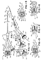
- Figure 2 is an isometric exploded view of the adjustable rotation limiter device shown in Figure 1;
- Figure 3 is a side elevational view of another embodiment of an adjustable rotation limiter device incorporating the present invention;
- Figure 4 is an isometric view of the torque knob used in the rotation limiter shown in Figure 3;
- Figure 5 is a side elevational view of still another embodiment of an adjustable rotational limiter device incorporating the present invention; and
- Figure 6 is an isometric view of the torque knob utilized in the rotation limiter device shown in Figure 5.
- The adjustable rotation limiter devices to be described are for use.. with steerable low-profile balloon dilatation catheters of the type which have a flexible core wire extending therethrough. An adapter is adapted to be secured to the proximal extremity of the dilatation catheter and has at least first and second arms. A fitting is carried by the first arm. Sealing means is disposed in the fitting. A first knob having a threaded axially extending member is threaded into the fitting and is adapted to engage the sealing means whereby when a core wire extends through the fitting, the sealing means and the first knob having the threaded member thereon, rotation of the first knob in one direction will cause the sealing means to form a sealing engagement with the core wire. A second knob which has a threaded axially extending member is threaded into the member carried by the first knob. Limit means is carried by one of the first and second knobs and has a portion thereof extending over the other of said knobs and serves to limit the rotational movement of the second knob with respect to the first knob. Means is provided for adjustably positioning the limit member carried by said one knob axially of the one knob whereby the number of revolutions of the second knob with respect to the first knob may be adjusted.
- More particularly as shown in Figures 1 and 2 of the drawings, the rotation limiter device 11 is shown as a part of a low-profile
steerable dilatation catheter 12. The low-profilesteerable dilatation catheter 12 is the type described in U.S. Patent Application Serial No. 615,118 filed May 3, 1984. As disclosed therein, it consists of aflexible core wire 13 formed of a suitable material such as stainless steel. It typically is formed of a length of 150 centimeters for a conventional catheter or approximately 40 centimeters for an intraoperative catheter. Thecore wire 13 is preferably circular in cross-section and has a diameter which is greater than .013 of an inch. As explained in U.S. Patent Application Serial No 615,118 filed May 30, 1984, the distal extremity of the core wire can be necked down at the distal extremity to provide greater flexibility at the distal extremity of the core wire. - A flexible
tubular member 14 formed of a suitable plastic material extends over the length of thecore wire 13. Aballoon 16 is carried by the distal extremity of thetubular member 14 and preferably is formed integral with thetubular member 14. Thetubular member 14 provides an annular flow passage or lumen 17 in conjunction with thecore wire 13 which extends the length of the core wire from the proximal end to the distal end of thetubular member 14 to establish communication with theballoon 16. The distal extremity of theballoon 16 is bonded to the distal extremity of thecore wire 13 to form a liquid-tight seal therebetween. Aflexible tip 18 is formed on the distal extremity of thecore wire 13'. - A
triple arm adapter 21 is secured to the proximal extremity of thetubular member 14. It is provided with a first orcentral arm 22 and second andthird side arms adapter 21 is provided with afitting 26 which has a threaded exterior with a conicaldistal extremity 27 over which the proximal extremity of thetubular member 14 is adapted to fit. An interiorly threadedcylindrical member 28 is provided for retaining the proximal extremity of thetubular member 14 on theconical portion 27 and is threaded onto thefitting 26. - The
central arm 22 carries an interiorly threadedfitting 31 which is generally conical in shape and is adapted to receive sealing means in the form of an a-ring 32. Athumb screw 33 is provided for engaging the O-ring 32 and clamping it into sealing engagement with thecore wire 13 which extends through thecentral arm 22 through the fitting 31 through the 0-ring 32 and through thethumb screw 33. - The
thumb screw 33 consists of aknurled knob 34 and carries an exteriorly threaded axially extending extension ormember 36 which is adapted to be threaded into thefitting 31 and engage the O-ring 32. Atorque knob 38 is provided for imparting rotational movement to thecore wire 13 and consists of aknurled knob 39 which has an exteriorally threaded axially extending extension ormember 41 carried thereby which is adapted to be threaded into an interiorly threaded bore 42 provided in thethumb screw 33. As shown, thecore wire 13 extends through thetorque knob 38 and is secured therein in a suitable manner such as by the use ofplastic 43 and aset screw 44 threaded into the knob and engaging thecore wire 13 so that thecore wire 13 will be rotated by the torque knob. - The rotation limiter device 11 in addition to including the
torque knob 38 includes a stop member. 46. which is generally in the form of an elongate cylinder. It is provided with an elongate cutout 47 extending longitudinally of the stop member. The cutout 47 provides spaced apartparallel lips stop member 46 is also provided with an elongate slot 51 which opens through the cutout 47. The slot 51 is adapted to receive ascrew 52. Thescrew 52 extends through the slot and is adapted to secure thestop member 46 to one of the knobs carried either by thethumb screw 33 or by thetorque knob 38. As shown in the drawings, thestop member 46 is secured to theknob 39 in such a manner that thelips knob 34 and overlie theknob 39 for a purpose hereinafter described. The stop member is provided with a conicalupper end 53 which is readily adapted to be engaged by a finger of the human hand. - The
side arm 23 also carries afitting 56 similar to thefitting 31 carried by thecentral arm 22 and is provided with an O-ring (not shown) which is adapted to be engaged by athumb screw 57. A bleed orvent wire 58 extends through thethumb screw 57 and through thearm 23 into the lumen provided by thetubular member 14 and into the distal extremity of theballoon 16. Theother arm 24 is adapted to receive a syringe or other suitable inflating device for introducing a saline solution or radiocontrast liquid into the lumen leading to theballoon 16 to inflate the balloon and to cause inflation of theballoon 16 and to cause any air therein to be expelled through the bleedwire 58. - Operation of the adjustable rotation limiter device may now be briefly described as follows. The use of steerable low profile dilatation balloon catheters is well known to those skilled in the art and will not be described in detail. The use of the rotation limiter device, however, in conjunction with the use of such a dilatation catheter will now be described. Let it be assumed that when the dilatation catheter is being manufactured that it is desirable to limit the revolution of the torque knob to a certain number of revolutions as, for example, two. Let it be assumed that each revolution of the torque knob causes axial movement of the
torque knob 38 with respect to thethumb screw 33 by an appropriate distance as, for example, .020 inches. Thus it can be seen by adjusting the gap between thelip 48 and the lower extremity of thethumb screw 34 that the number of revolutions which thetorque knob 38 can be rotated before thelip 48 engages the lower extremity of thethumb screw 33 and prevents further rotation can be readily adjusted. Thus as soon as the desired gap between thelip 48 and the lower extremity of thethumb screw 33 has been ascertained, thestop member 46 can be fixed in position on theknob 39 by tightening thescrew 52. If desired, thescrew 52 can be provided with special means as, for example, a Phillips head or an Allen head to discourage tampering with the positioning of thestop member 46 away from the factory. By providing a cutout 47 of appropriate length it can be seen that various spacings can be provided between thelip 48 and the lower extremity of theknob 34 of thethumb screw 33. For example, by providing a gap of .060 rather than .020, the number of revolutions can be increased from 1 to 3. - It also should be appreciated that rather than mounting the
stop member 46 on theknob 39, the stop member alternatively can be mounted on theknob 34 in which case the spacing between thelip 49 and the upper surface of theknob 39 would control the number of revolutions for thetorque knob 38. - Another embodiment of a rotation limiter device is a
device 59 incorporating the present invention shown in Figures 3 and 4. As shown therein, it consists of athumb screw 61 which is threaded into the fitting 31. Thethumb screw 61 is similar to thethumb screw 33 hereinbefore described with the exception that it is provided with achamfer 62 for the purpose hereinafter described. Therotation limiter 59 includes atorque knob 66. Thetorque knob 66 consists of aknob 67 which carries an externally threaded axially extendingextension member 68. Thetorque knob 66 can be formed of a suitable material such as plastic and is provided with first and second diametrically opposed legs orarms 69 which extend in a direction parallel to themember 68. The distal extremities of thearms 69 are provided with inwardly extending abutments orlips 71 which are formed integral therewith and which are spaced a predetermined distance from the innermost surface of theknob 67. Anupstanding protrusion 72 is formed on theknob 67 and is offset to one side thereof and extends outwardly from the outer extremity of theknob 67. Theprotrusion 72 is adapted to be engaged by a finger of a hand. Theguide wire 13 hereinbefore described extends through thetorque knob 66 and is secured thereto by an epoxy 43 as well as by aset screw 74. - Operation of this embodiment of the
rotation limiter device 59 is similar to that hereinbefore described in conjunction with Figures 1 and 2. In assembling the rotation limiter device, thetorque knob 66 has itsmember 68 threaded into thethumb screw 61 in such a manner so that the lowermost curved extremities of the abutments orlips 71 engage thechamfer 62 on thethumb screw 61. Thechamfer 62 urges the lower extremities of thearms 69 outwardly as continued rotation of thetorque knob 66 moves the legs orarms 69 downwardly until the abutments orlips 71 clear the side margins of the thumb screw and thereafter snap over the lower extremities of thethumb screw 61. - As soon as this occurs, it can be seen that the
torque knob 66 can continue to be rotated until the lower surface of theknob 67 engages the upper surface of thethumb screw 61. Also, it can be seen that the amount of rotation of thetorque knob 67 is limited by thearms 69, with the number of rotations of thetorque knob 66 being controlled by the full length of thearms 69. As soon as the lips orabutments 71 engage the lower surface of thethumb screw 61, further rotation will be prevented. - It can be seen that by providing
torque knobs 66 witharms 69 of variable lengths, that rotation of atorque knob 66 can be limited to a predetermined amount as, for example, one turn, two turns, or three turns, as the case may be. Therotation limiter device 59 in addition to being relatively simple prevents canting of thetorque knob 66 because arms orlegs 69 are provided on diametrically opposite sides of the threadedarm member 68. In addition, thetorque knob 66 can be readily rotated by a finger engaging thecylindrical protrusion 72. - Thus it can be seen that by controlling the length of the slot 51 and the overall spacing between
lips arms 69 of various lengths in the embodiment shown in Figures 3 and 4, the number of possible revolutions can be readily selected. This makes it possible to provide a rotation limiter device which can be utilized with dilatation catheters of various lengths and thereby preventing over rotation of the core wire and undue distortion of the balloon. It also is apparent that there has been provided a relatively simple rotation limiter device which can be readily manufactured which is provided with a minimum number of parts. - Still another embodiment of a rotation limiter device is a
device 76 shown in Figures 5 and 6 incorporating the present invention. As shown therein, thedevice 76 consists of athumb screw 77 which is threaded into the fitting 31. Thethumb screw 77 is similar to thethumb screw 61 hereinbefore described with the exception that it is not provided with a chamfer. Thus thethumb screw 77 is provided with acylindrical unknurled portion 78. Therotation limiter device 76 also includes atorque knob 79. Thetorque knob 79 includes acylindrical member 81 in the form of a knob which carries an external axially extendingextension member 82. Thetorque knob 79 is provided with first and second diametrically opposed legs orarms 83 which extend in a direction parallel to theextension member 82. Means is carried by the distal extremities of the legs orarms 83 to stiffen the legs or arms and to prevent the legs orarms 83 from being cammed outwardly and consists of aring 84 which has its outer circumference bonded to the distal extremities of theleg 83 by suitable means such as an epoxy. Thering 84 is provided with upper and lowerannular surfaces 86. Theupper surface 86 is adapted to engage and seat against the lower surface of thethumb screw 77 as hereinafter described. Aprotrusion 88 is carried by thetorque knob 79 and is adapted to be engaged by the finger of a hand to facilitate rotation of thetorque knob 79. Theguide wire 13 hereinbefore described extends through thetorque knob 79 and is secured thereto by abody 89 of a suitable epoxy as well as by aset screw 91. - In manufacture of the
rotation limiter device 76, the assembly is the same as hereinbefore described with respect to the previous embodiments except that thering 84 is bonded to the distal extremities of thelegs 83 after thelegs 83 have been passed over thetorque knob 79. As soon as this has been accomplished, the circumferential portions of thering 84 can be bonded to the distal extremities of thelegs 83 by suitable means such as an epoxy. - Operation of this embodiment of the rotation limiter device is similar to that hereinbefore described in conjunction with the embodiment shown in Figures 3 and 4. The length of the
legs 83 as well as the pitch of the threads on theextension member 82 have been chosen so that the desired amount of rotation can be obtained, as for example, three rotations, through 3600 for each rotation. - With the arrangement shown it can be seen that the
torque knob 79 can be rotated in counterclockwise direction so that thetorque knob 79 moves outwardly with respect to thethumb screw 77. This can continue until thetop surface 86 of theannular ring 84 comes into engagement with the lower surface of thethumb screw 77 inhibiting further rotation. Typically the length of the legs and the relationship with the threads on theextension member 82 can be selected so that a predetermined number of turns as, for example, a maximum of three turns are permitted. This helps to ensure that there will not be over rotation of the balloon carried by the catheter. The use of theannular ring 84 is particularly advantageous in that it prohibits any inadvertent possible snapping outwardly of thelegs 83 and thus provides assurance that the rotation of theguide wire 18 cannot exceed a total of three revolutions. It should be appreciated that if desired, the legs orarms 83 can be made shorter or longer with respect to the threads on theextension member 82 to provide the desired number of revolutions. This makes it possible to precisely control the rotation so that the balloon carried by the end of the catheter will not be unduly twisted. - It is apparent from the foregoing that there has been provided a rotation limiting device in various types of embodiments serving to prevent undue rotation of the balloon carried by the catheter. The rotation limiting devices are relatively simple in construction and can be readily and economically manufactured.
Claims (12)
Applications Claiming Priority (4)
| Application Number | Priority Date | Filing Date | Title |
|---|---|---|---|
| US615139 | 1975-09-19 | ||
| US61513984A | 1984-05-30 | 1984-05-30 | |
| US732641 | 1985-05-10 | ||
| US06/732,641 US4619263A (en) | 1984-05-30 | 1985-05-10 | Adjustable rotation limiter device for steerable dilatation catheters |
Publications (2)
| Publication Number | Publication Date |
|---|---|
| EP0165727A1 true EP0165727A1 (en) | 1985-12-27 |
| EP0165727B1 EP0165727B1 (en) | 1988-07-13 |
Family
ID=27087429
Family Applications (1)
| Application Number | Title | Priority Date | Filing Date |
|---|---|---|---|
| EP85303732A Expired EP0165727B1 (en) | 1984-05-30 | 1985-05-28 | Catheter rotary assembly |
Country Status (4)
| Country | Link |
|---|---|
| US (1) | US4619263A (en) |
| EP (1) | EP0165727B1 (en) |
| CA (1) | CA1238544A (en) |
| DE (1) | DE3563687D1 (en) |
Cited By (7)
| Publication number | Priority date | Publication date | Assignee | Title |
|---|---|---|---|---|
| EP0213752A1 (en) * | 1985-07-30 | 1987-03-11 | Advanced Cardiovascular Systems, Inc. | Steerable balloon dilatation catheter assembly having dye injection and pressure measurement capabilities |
| EP0213751A1 (en) * | 1985-07-30 | 1987-03-11 | Advanced Cardiovascular Systems, Inc. | Steerable dilatation catheter with rotation limiting device |
| EP0279958A1 (en) * | 1987-01-06 | 1988-08-31 | Advanced Cardiovascular Systems, Inc. | Liquid filled low profile dilatation catheter |
| EP0335581A2 (en) * | 1988-03-28 | 1989-10-04 | Schneider (Usa) Inc. | Catheter Y-connector with guidewire locking means |
| US4976720A (en) * | 1987-01-06 | 1990-12-11 | Advanced Cardiovascular Systems, Inc. | Vascular catheters |
| WO1992007608A1 (en) * | 1990-10-31 | 1992-05-14 | Baxter International Inc. | Over-the-wire catheter |
| EP3944054A1 (en) * | 2018-04-05 | 2022-01-26 | Medos International Sarl | Surgical instruments with rotation stop devices and related methods |
Families Citing this family (78)
| Publication number | Priority date | Publication date | Assignee | Title |
|---|---|---|---|---|
| US4944740A (en) * | 1984-09-18 | 1990-07-31 | Medtronic Versaflex, Inc. | Outer exchange catheter system |
| US5114414A (en) * | 1984-09-18 | 1992-05-19 | Medtronic, Inc. | Low profile steerable catheter |
| US4960411A (en) * | 1984-09-18 | 1990-10-02 | Medtronic Versaflex, Inc. | Low profile sterrable soft-tip catheter |
| US5061273A (en) * | 1989-06-01 | 1991-10-29 | Yock Paul G | Angioplasty apparatus facilitating rapid exchanges |
| US5350395A (en) * | 1986-04-15 | 1994-09-27 | Yock Paul G | Angioplasty apparatus facilitating rapid exchanges |
| US5125895A (en) * | 1986-07-22 | 1992-06-30 | Medtronic Versaflex, Inc. | Steerable catheter |
| US4723936A (en) * | 1986-07-22 | 1988-02-09 | Versaflex Delivery Systems Inc. | Steerable catheter |
| US4846174A (en) * | 1986-08-08 | 1989-07-11 | Scimed Life Systems, Inc. | Angioplasty dilating guide wire |
| US4838859A (en) * | 1987-05-19 | 1989-06-13 | Steve Strassmann | Steerable catheter |
| US5055109A (en) * | 1989-10-05 | 1991-10-08 | Advanced Cardiovascular Systems, Inc. | Torque transmitting assembly for intravascular devices |
| US5345945A (en) * | 1990-08-29 | 1994-09-13 | Baxter International Inc. | Dual coil guidewire with radiopaque distal tip |
| EP0476807A1 (en) * | 1990-09-17 | 1992-03-25 | C.R. Bard, Inc. | Core wire steerable catheters |
| US5163911A (en) * | 1990-10-31 | 1992-11-17 | Baxter International Inc. | Over-the-wire catheter |
| US5185004A (en) * | 1991-06-03 | 1993-02-09 | Danforth Biomedical, Inc. | Turn-limiting proximal adaptor for steerable catheter systems |
| EP0592720B1 (en) * | 1991-06-10 | 1998-07-29 | Cordis Corporation | Replaceable dilatation catheter |
| US5205822A (en) * | 1991-06-10 | 1993-04-27 | Cordis Corporation | Replaceable dilatation catheter |
| CA2074304C (en) * | 1991-08-02 | 1996-11-26 | Cyril J. Schweich, Jr. | Drug delivery catheter |
| US5327905A (en) * | 1992-02-14 | 1994-07-12 | Boaz Avitall | Biplanar deflectable catheter for arrhythmogenic tissue ablation |
| US5352197A (en) * | 1992-03-18 | 1994-10-04 | The Spectranetics Corporation | Turn limiter for a catheter with twistable tip |
| WO1993018818A1 (en) * | 1992-03-18 | 1993-09-30 | The Spectranetics Corporation | Fiber optic catheter with twistable tip |
| US5290230A (en) * | 1992-05-11 | 1994-03-01 | Advanced Cardiovascular Systems, Inc. | Intraluminal catheter with a composite shaft |
| US5287857A (en) * | 1992-06-22 | 1994-02-22 | David Mann | Apparatus and method for obtaining an arterial biopsy |
| US5456680A (en) * | 1993-09-14 | 1995-10-10 | Spectranetics Corp | Fiber optic catheter with shortened guide wire lumen |
| US5624379A (en) * | 1995-10-13 | 1997-04-29 | G. I. Medical Technologies, Inc. | Endoscopic probe with discrete rotatable tip |
| US5830183A (en) * | 1997-06-30 | 1998-11-03 | Schneider (Usa) Inc | Clip device for vascular catheter |
| US9254143B2 (en) | 1998-02-25 | 2016-02-09 | Revascular Therapeutics, Inc. | Guidewire for crossing occlusions or stenoses having a shapeable distal end |
| US6059767A (en) * | 1998-02-25 | 2000-05-09 | Norborn Medical, Inc. | Steerable unitary infusion catheter/guide wire incorporating detachable infusion port assembly |
| US20050119615A1 (en) * | 2000-04-06 | 2005-06-02 | Norborn Medical, Inc. | Guidewire for crossing occlusions or stenoses |
| US20070225615A1 (en) * | 2006-03-22 | 2007-09-27 | Revascular Therapeutics Inc. | Guidewire controller system |
| US20080140101A1 (en) * | 2006-12-07 | 2008-06-12 | Revascular Therapeutic, Inc. | Apparatus for crossing occlusions or stenoses |
| US6746422B1 (en) | 2000-08-23 | 2004-06-08 | Norborn Medical, Inc. | Steerable support system with external ribs/slots that taper |
| US6824550B1 (en) | 2000-04-06 | 2004-11-30 | Norbon Medical, Inc. | Guidewire for crossing occlusions or stenosis |
| US6740104B1 (en) * | 1998-05-15 | 2004-05-25 | Advanced Cardiovascular Systems, Inc. | Enhanced catheter with alignment means |
| JP2002515308A (en) | 1998-05-15 | 2002-05-28 | メジネイション,インク. | Enhanced balloon expansion system |
| US6780199B2 (en) | 1998-05-15 | 2004-08-24 | Advanced Cardiovascular Systems, Inc. | Enhanced stent delivery system |
| US20020007145A1 (en) | 1998-10-23 | 2002-01-17 | Timothy Stivland | Catheter having improved bonding region |
| US7381198B2 (en) | 2000-08-23 | 2008-06-03 | Revascular Therapeutics, Inc. | Steerable distal support system |
| US7071898B2 (en) * | 2002-07-18 | 2006-07-04 | Information Decision Technologies, Llc | Method for using a wireless motorized camera mount for tracking in augmented reality |
| US8591540B2 (en) | 2003-02-27 | 2013-11-26 | Abbott Cardiovascular Systems Inc. | Embolic filtering devices |
| US7582740B2 (en) * | 2003-04-17 | 2009-09-01 | The Trustees Of Columbia University In The City Of New York | Methods and kits for detecting SARS-associated coronavirus |
| US20050209674A1 (en) * | 2003-09-05 | 2005-09-22 | Kutscher Tuvia D | Balloon assembly (V) |
| US20050159728A1 (en) * | 2004-01-15 | 2005-07-21 | Thomas Medical Products, Inc. | Steerable sheath |
| US20060089569A1 (en) * | 2004-10-26 | 2006-04-27 | Soukup Thomas M | Articulator with adjustable stiffness distal portion |
| US20060184105A1 (en) * | 2005-02-15 | 2006-08-17 | Townsend Gregory L | Thin wall catheter and method of placing same |
| US7892186B2 (en) * | 2005-12-09 | 2011-02-22 | Heraeus Materials S.A. | Handle and articulator system and method |
| JP4905647B2 (en) * | 2006-02-14 | 2012-03-28 | 朝日インテック株式会社 | Medical tools |
| US8926620B2 (en) | 2006-08-25 | 2015-01-06 | Kyphon Sarl | Apparatus and methods for use of expandable members in surgical applications |
| US7985228B2 (en) * | 2006-08-25 | 2011-07-26 | Kyphon Sarl | Apparatus and methods for use of expandable members in surgical applications |
| US20090131831A1 (en) * | 2007-11-15 | 2009-05-21 | Wright-Ahn Technologies, Llc | Variable Stiffness Guidewire Systems |
| US20090131867A1 (en) | 2007-11-16 | 2009-05-21 | Liu Y King | Steerable vertebroplasty system with cavity creation element |
| US9510885B2 (en) | 2007-11-16 | 2016-12-06 | Osseon Llc | Steerable and curvable cavity creation system |
| US8070694B2 (en) | 2008-07-14 | 2011-12-06 | Medtronic Vascular, Inc. | Fiber based medical devices and aspiration catheters |
| US8657821B2 (en) | 2008-11-14 | 2014-02-25 | Revascular Therapeutics Inc. | Method and system for reversibly controlled drilling of luminal occlusions |
| US8162891B2 (en) | 2008-11-26 | 2012-04-24 | Revascular Therapeutics, Inc. | Delivery and exchange catheter for storing guidewire |
| US20100298832A1 (en) | 2009-05-20 | 2010-11-25 | Osseon Therapeutics, Inc. | Steerable curvable vertebroplasty drill |
| US8702689B2 (en) | 2009-09-01 | 2014-04-22 | Boston Scientific Scimed, Inc. | Systems and methods for twisting an expansion element of a cryoablation system |
| WO2011137377A1 (en) | 2010-04-29 | 2011-11-03 | Dfine, Inc. | System for use in treatment of vertebral fractures |
| US9326872B2 (en) * | 2010-08-17 | 2016-05-03 | W. L. Gore & Associates, Inc. | Forced deployment sequence handle assembly with independent actuating mechanism |
| EP4101399A1 (en) | 2011-08-05 | 2022-12-14 | Route 92 Medical, Inc. | System for treatment of acute ischemic stroke |
| US8814832B1 (en) * | 2013-02-15 | 2014-08-26 | Ibrahim Rashid Al-Rashdan | Expandable sheath and system for intravascular insertion of a medical implement using the same |
| JP6204085B2 (en) * | 2013-06-27 | 2017-09-27 | オリンパス株式会社 | Endoscopic treatment tool and endoscope system |
| US9265512B2 (en) | 2013-12-23 | 2016-02-23 | Silk Road Medical, Inc. | Transcarotid neurovascular catheter |
| US9820761B2 (en) | 2014-03-21 | 2017-11-21 | Route 92 Medical, Inc. | Rapid aspiration thrombectomy system and method |
| US10426497B2 (en) | 2015-07-24 | 2019-10-01 | Route 92 Medical, Inc. | Anchoring delivery system and methods |
| US11065019B1 (en) | 2015-02-04 | 2021-07-20 | Route 92 Medical, Inc. | Aspiration catheter systems and methods of use |
| WO2016126974A1 (en) | 2015-02-04 | 2016-08-11 | Route 92 Medical, Inc. | Rapid aspiration thrombectomy system and method |
| US10716915B2 (en) | 2015-11-23 | 2020-07-21 | Mivi Neuroscience, Inc. | Catheter systems for applying effective suction in remote vessels and thrombectomy procedures facilitated by catheter systems |
| US11229445B2 (en) | 2016-10-06 | 2022-01-25 | Mivi Neuroscience, Inc. | Hydraulic displacement and removal of thrombus clots, and catheters for performing hydraulic displacement |
| JP2019534130A (en) | 2016-10-27 | 2019-11-28 | ディーファイン,インコーポレイティド | Articulated osteotome with cement delivery channel |
| US11116570B2 (en) | 2016-11-28 | 2021-09-14 | Dfine, Inc. | Tumor ablation devices and related methods |
| WO2018107036A1 (en) | 2016-12-09 | 2018-06-14 | Dfine, Inc. | Medical devices for treating hard tissues and related methods |
| WO2018129180A1 (en) | 2017-01-06 | 2018-07-12 | Dfine, Inc. | Osteotome with a distal portion for simultaneous advancement and articulation |
| CN110392591B (en) | 2017-01-10 | 2022-06-03 | 92号医疗公司 | Aspiration catheter system and method of use |
| US11234723B2 (en) | 2017-12-20 | 2022-02-01 | Mivi Neuroscience, Inc. | Suction catheter systems for applying effective aspiration in remote vessels, especially cerebral arteries |
| US10478535B2 (en) | 2017-05-24 | 2019-11-19 | Mivi Neuroscience, Inc. | Suction catheter systems for applying effective aspiration in remote vessels, especially cerebral arteries |
| CN115999019A (en) | 2018-05-17 | 2023-04-25 | 92号医疗公司 | Aspiration catheter system and method of use |
| EP3876856A4 (en) | 2018-11-08 | 2022-10-12 | Dfine, Inc. | Tumor ablation device and related systems and methods |
| US11617865B2 (en) | 2020-01-24 | 2023-04-04 | Mivi Neuroscience, Inc. | Suction catheter systems with designs allowing rapid clearing of clots |
Citations (3)
| Publication number | Priority date | Publication date | Assignee | Title |
|---|---|---|---|---|
| WO1981002110A1 (en) * | 1980-01-30 | 1981-08-06 | T Fogarty | Dilatation catheter apparatus and method |
| EP0047465A1 (en) * | 1980-09-10 | 1982-03-17 | Kontron Incorporated | Percutaneous balloon catheter |
| US4332254A (en) * | 1980-11-17 | 1982-06-01 | Advanced Catheter Systems, Inc. | System for filling and inflating and deflating a vascular dilating cathether assembly |
Family Cites Families (5)
| Publication number | Priority date | Publication date | Assignee | Title |
|---|---|---|---|---|
| US3503385A (en) * | 1965-09-27 | 1970-03-31 | Cordis Corp | Guidable catheter assembly and manipulator therefor |
| US3552384A (en) * | 1967-07-03 | 1971-01-05 | American Hospital Supply Corp | Controllable tip guide body and catheter |
| US4403612A (en) * | 1980-10-20 | 1983-09-13 | Fogarty Thomas J | Dilatation method |
| US4338942A (en) * | 1980-10-20 | 1982-07-13 | Fogarty Thomas J | Dilatation catherter apparatus |
| US4422447A (en) * | 1981-04-13 | 1983-12-27 | Peter Schiff | Percutaneous balloon |
-
1985
- 1985-05-10 US US06/732,641 patent/US4619263A/en not_active Expired - Lifetime
- 1985-05-28 EP EP85303732A patent/EP0165727B1/en not_active Expired
- 1985-05-28 DE DE8585303732T patent/DE3563687D1/en not_active Expired
- 1985-05-29 CA CA000482668A patent/CA1238544A/en not_active Expired
Patent Citations (3)
| Publication number | Priority date | Publication date | Assignee | Title |
|---|---|---|---|---|
| WO1981002110A1 (en) * | 1980-01-30 | 1981-08-06 | T Fogarty | Dilatation catheter apparatus and method |
| EP0047465A1 (en) * | 1980-09-10 | 1982-03-17 | Kontron Incorporated | Percutaneous balloon catheter |
| US4332254A (en) * | 1980-11-17 | 1982-06-01 | Advanced Catheter Systems, Inc. | System for filling and inflating and deflating a vascular dilating cathether assembly |
Cited By (11)
| Publication number | Priority date | Publication date | Assignee | Title |
|---|---|---|---|---|
| EP0213752A1 (en) * | 1985-07-30 | 1987-03-11 | Advanced Cardiovascular Systems, Inc. | Steerable balloon dilatation catheter assembly having dye injection and pressure measurement capabilities |
| EP0213751A1 (en) * | 1985-07-30 | 1987-03-11 | Advanced Cardiovascular Systems, Inc. | Steerable dilatation catheter with rotation limiting device |
| AU598472B2 (en) * | 1985-07-30 | 1990-06-28 | Advanced Cardiovascular Systems Inc. | Steerable dilatation catheter with rotation limiting device |
| EP0279958A1 (en) * | 1987-01-06 | 1988-08-31 | Advanced Cardiovascular Systems, Inc. | Liquid filled low profile dilatation catheter |
| US4976720A (en) * | 1987-01-06 | 1990-12-11 | Advanced Cardiovascular Systems, Inc. | Vascular catheters |
| EP0335581A2 (en) * | 1988-03-28 | 1989-10-04 | Schneider (Usa) Inc. | Catheter Y-connector with guidewire locking means |
| EP0335581A3 (en) * | 1988-03-28 | 1991-08-07 | Schneider (Usa) Inc. | Catheter y-connector with guidewire locking means |
| WO1992007608A1 (en) * | 1990-10-31 | 1992-05-14 | Baxter International Inc. | Over-the-wire catheter |
| EP3944054A1 (en) * | 2018-04-05 | 2022-01-26 | Medos International Sarl | Surgical instruments with rotation stop devices and related methods |
| US11294414B2 (en) | 2018-04-05 | 2022-04-05 | Medos International Sàrl | Surgical instruments with rotation stop devices |
| US11832788B2 (en) | 2018-04-05 | 2023-12-05 | Medos International Sarl | Surgical instruments with rotation stop devices and related methods |
Also Published As
| Publication number | Publication date |
|---|---|
| CA1238544A (en) | 1988-06-28 |
| EP0165727B1 (en) | 1988-07-13 |
| DE3563687D1 (en) | 1988-08-18 |
| US4619263A (en) | 1986-10-28 |
Similar Documents
| Publication | Publication Date | Title |
|---|---|---|
| US4619263A (en) | Adjustable rotation limiter device for steerable dilatation catheters | |
| US4664113A (en) | Steerable dilatation catheter with rotation limiting device | |
| JP4691528B2 (en) | Adjustable two-way valve structure for controlling fluid flow and method for adjusting critical pressure differential | |
| US5591136A (en) | Injection device | |
| EP0222088B1 (en) | Liquid flow regulator | |
| US4210174A (en) | Positive pressure valves | |
| US4403988A (en) | Syringe assembly | |
| CA1193939A (en) | Catheter guide | |
| US8146592B2 (en) | Method and apparatus for regulating fluid flow or conserving fluid flow | |
| US4443214A (en) | Valve for the treatment of hydrocephalus | |
| US4676772A (en) | Adjustable implantable valve having non-invasive position indicator | |
| US5097827A (en) | Holder for medical tubing | |
| US4147170A (en) | Catheter with inflation control device | |
| US4620690A (en) | Modular flow control cassette | |
| EP0324641B1 (en) | Shear force gauge | |
| KR20100087079A (en) | Adjustable valve | |
| US4074714A (en) | Syringe assembly | |
| US4240430A (en) | Syringe assembly | |
| US3042067A (en) | Tube clamp | |
| US4030497A (en) | Syringe assembly | |
| CA1159736A (en) | Adjustable in-line intravenous valve with locking mechanism | |
| US4671320A (en) | Adjustable valve for liquids for equipment having a medical application | |
| US6929235B1 (en) | Apparatus for flow rate control | |
| US4284084A (en) | Syringe assembly | |
| US5293866A (en) | Oxygen flow meter indicator |
Legal Events
| Date | Code | Title | Description |
|---|---|---|---|
| PUAI | Public reference made under article 153(3) epc to a published international application that has entered the european phase |
Free format text: ORIGINAL CODE: 0009012 |
|
| AK | Designated contracting states |
Designated state(s): CH DE FR GB LI |
|
| 17P | Request for examination filed |
Effective date: 19860520 |
|
| 17Q | First examination report despatched |
Effective date: 19870601 |
|
| GRAA | (expected) grant |
Free format text: ORIGINAL CODE: 0009210 |
|
| AK | Designated contracting states |
Kind code of ref document: B1 Designated state(s): CH DE FR GB LI |
|
| REF | Corresponds to: |
Ref document number: 3563687 Country of ref document: DE Date of ref document: 19880818 |
|
| ET | Fr: translation filed | ||
| PLBE | No opposition filed within time limit |
Free format text: ORIGINAL CODE: 0009261 |
|
| STAA | Information on the status of an ep patent application or granted ep patent |
Free format text: STATUS: NO OPPOSITION FILED WITHIN TIME LIMIT |
|
| 26N | No opposition filed | ||
| PGFP | Annual fee paid to national office [announced via postgrant information from national office to epo] |
Ref country code: FR Payment date: 19910314 Year of fee payment: 7 |
|
| PGFP | Annual fee paid to national office [announced via postgrant information from national office to epo] |
Ref country code: GB Payment date: 19910415 Year of fee payment: 7 |
|
| PGFP | Annual fee paid to national office [announced via postgrant information from national office to epo] |
Ref country code: DE Payment date: 19910429 Year of fee payment: 7 |
|
| PGFP | Annual fee paid to national office [announced via postgrant information from national office to epo] |
Ref country code: CH Payment date: 19910614 Year of fee payment: 7 |
|
| PG25 | Lapsed in a contracting state [announced via postgrant information from national office to epo] |
Ref country code: GB Effective date: 19920528 |
|
| PG25 | Lapsed in a contracting state [announced via postgrant information from national office to epo] |
Ref country code: LI Effective date: 19920531 Ref country code: CH Effective date: 19920531 |
|
| GBPC | Gb: european patent ceased through non-payment of renewal fee |
Effective date: 19920528 |
|
| PG25 | Lapsed in a contracting state [announced via postgrant information from national office to epo] |
Ref country code: FR Effective date: 19930129 |
|
| REG | Reference to a national code |
Ref country code: CH Ref legal event code: PL |
|
| PG25 | Lapsed in a contracting state [announced via postgrant information from national office to epo] |
Ref country code: DE Effective date: 19930202 |
|
| REG | Reference to a national code |
Ref country code: FR Ref legal event code: ST |