EP0164842A2 - Power assistance steering systems for vehicles - Google Patents
Power assistance steering systems for vehicles Download PDFInfo
- Publication number
- EP0164842A2 EP0164842A2 EP85302609A EP85302609A EP0164842A2 EP 0164842 A2 EP0164842 A2 EP 0164842A2 EP 85302609 A EP85302609 A EP 85302609A EP 85302609 A EP85302609 A EP 85302609A EP 0164842 A2 EP0164842 A2 EP 0164842A2
- Authority
- EP
- European Patent Office
- Prior art keywords
- steering
- pump
- fluid pressure
- power assistance
- vehicle
- Prior art date
- Legal status (The legal status is an assumption and is not a legal conclusion. Google has not performed a legal analysis and makes no representation as to the accuracy of the status listed.)
- Withdrawn
Links
Images
Classifications
-
- B—PERFORMING OPERATIONS; TRANSPORTING
- B62—LAND VEHICLES FOR TRAVELLING OTHERWISE THAN ON RAILS
- B62D—MOTOR VEHICLES; TRAILERS
- B62D5/00—Power-assisted or power-driven steering
- B62D5/06—Power-assisted or power-driven steering fluid, i.e. using a pressurised fluid for most or all the force required for steering a vehicle
Definitions
- This invention relates to power assistance steering systems for vehicles.
- An object of the present invention is to provide an improved power assistance steering system for vehicles and/or such a system offering advantages in relation to one or more of the following factors, namely manufacturing cost, simplicity of operation, reliability of operation, and related factors.
- a power assistance steering system for a vehicle in which a fluid pump delivers hydraulic fluid to a servo motor in the form of a hydraulic ram connected to the vehicle steering gear to provide power assistance.
- An input sensor in the form of a strain gauge or torque sensor is associated with the input means of the steering system so as to sense the torque or thrust generated in the steering system by the driver of the vehicle by use of the steering wheel.
- a fluid pressure control system is provided to control the fluid pressure supplied to the servo motor in accordance with signals generated by the input sensor.
- the fluid pressure control system comprises a direction switch responsive to the driver's intended vehicle direction, and the torque sensor is connected to a micro-processor which controls both a solenoid operated valve and an electric motor driving the pump.
- the solenoid operated valve directs the fluid pressure to the relevant chamber of the double acting ram of the servo motor.
- the micro-processor controls the electric motor driving the pump so that the latter is driven at varying speeds so as to provide a variable output pressure in accordance with the requirements of the servo-motor as sensed by the input sensor.
- the solenoid operated valve is constructed to move to a fully open position on actuation, and the pressure control determining the degree of power assistance is provided by variation of the pumpspeed.
- the solenoid operated valve is likewise constructed to move to a fully open position on actuated, but pressure control is provided by a control valve on the upstream side of the solenoid operated valve.
- Both of these embodiments have the advantage that the construction of the solenoid operated valve is greatly simplified, and hence its cost is reduced, since it is not required to provide pressure control. Moreover, the separation of the functions of direction control and pressure control leads to greater reliability in service.
- the pump is arranged to be driven only during operation of the power assistance system, and is not driven during non power-assisted vehicle steering movements. In an embodiment, this is achieved by means of an electric motor drive for the pump and appropriate control signals thereto from the micro-processor.
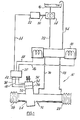
- a power assistance steering system 10 for a vehicle comprises steering gear 12 having an internal hydraulic ram (not shown) supplied with hydraulic fluid by a pump 14 from a reservoir 16 via a solenoid valve 18 controlled by a micro-processor 20 which also controls an electric motor 22 for driving pump 14.
- Steering gear 12 comprises a main body 24 housing the hydraulic ram which constitutes a servo motor for the power assistance steering system.
- main body 24 gaiters 26, 28 project endwise and engage and protect steering links (not shown) connected to the steerable wheels of the vehicle, the links being arranged to be power-operated by the ram and to be manually operated by a conventional rack and pinion steering system housed within main body 24 and connected via a steering shaft 3D to a driver's steering wheel of the vehicle.
- Steering shaft 30 is rotatably mounted in a pinion housing 32 forming part of main body 24 and in which a pinion which is rotatable with steering shaft 30 is housed and engages the rack (not shown) connected to the steering links.
- pinion housing 32 Also located within pinion housing 32 are a direction switch 34 and a torque sensor 36 which are connected by conductors 38, 40 and 42 to micro-processor 20 and hence by conductors 44, 46 and 48 to pump motor 22 and solenoid. valve 18.
- Hydraulic conduits 52, 54 connect reservoir 16 to solenoid valve 18 and provide , respectively, a hydraulic pressure flow and a return flow.
- Conduits 56, 58 connect solenoid valve 18 to the ram housed within main body 24, and each provides for a two-way hydraulic flow, according to the direction of actuation of the ram.
- the system operates as follows. Steering-input torque is sensed by torque sensor 36 and steering direction is sensed by direction switch 34. Output signals from these devices are fed to micro-processor 20 which controls solenoid valve 18 and pump motor 22 accordingly so that steering gear 12 is appropriately actuated.
- Torque sensor 36 may comprise a strain gauge mounted on steering shaft 30 or elsewhere in the steering gear between the driver's steering wheel and the hydraulic ram or servo motor. Other steering input sensing devices may equally be used so as to provide an electrical output signal related to the driver's input torque.
- Direction switch 34 provides an output signal to the micro-processor indicating the required direction of power assistance so that, by appropriate actuation of solenoid valve 18, the relevant chamber in the double acting ram in main body 24 is pressurised - the other chamber being connected through valve 18 to reservoir 16.
- Solenoid valve 18 also provides for conduits 56, 58 to be freely interconnected when power assistance is not required so that manual steering can be effected by means of the rack and pinion steering system.
- Micro-processor 20 is arranged to control the electric motor 22 for pump 14 so as to vary the motor speed in accordance with the pressure requirements of the steering ram or servo motor - as sensed by torque sensor 36.
- the pump motor is driven fast to provide a high pressure hydraulic output for the ram, and conversely when the torque input is lower, a lower hydraulic pressure is provided by driving the pump motor more slowly.
- the solenoid valve 18 is constructed so as to be either fully open or fully closed, with no significant intermediate position. With this arrangement, the variable pump speed enables the operation of the steering ram nevertheless to be controlled in a quantitative way.
- Micro-processor 20 provides valve-opening and direction control signals through conductors 46, 48 to solenoid valve 18 for the purpose described above.
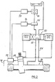
- Pump 70 is driven by electric motor 72 at a generally constant speed, or may be mechanically driven by the engine of the vehicle, so as to provide a fairly constant fluid output pressure.
- a proportional control valve 74 Downstream of pump 70 is provided a proportional control valve 74 which is operated by an actuator 76, such as a solenoid actuator, controlled by a micro-processor 78.
- Solenoid operated valve 80 again provides steering direction control by directing the fluid pressure output to either of fluid output lines 82, 84 which are connected to the relevant chambers of the double acting ram of the steering gear 86.
- Direction control signals derive from direction switch 88 as in the previous embodiment, but pas-s direct to the solenoid valve 80.
- An electrical input 90 is provided on micro-processor 78 for signals from, for example, a vehicle speed sensor.
- the micro-processor also provides amplification functions.
- Proportional control valve 74 may be of the axial or rotary kind, having an open or closed centre, with a single input and a single output connection. As in the case of solenoid valve 80, control valve 74 may be a spool valve, but it is in any case arranged to be operated by actuator 76 so as to provide a controlled fluid pressure output to the on/off direction control valve 80.
- a further feature of the fluid pressure control system of Fig 1 which is applicable also to that of Fig 2 is provided by the characteristic of the micro-processor 20 whereby pump 14 is driven only during operation of the power assistance system and is not driven during non power-assisted steering movements.
- This feature is provided by means of the electric motor 22 which drives the pump under the control of micro-processor20 - as opposed to the more usual drive arrangement in which a belt drive from the engine of the vehicle is provided whereby the pump is driven at all times and provision has to be made for dumping to tank the fluid pressure generated in excess of the steering ram's requirements.
- a related feature of the fluid pressure control system also resides in the function of micro-processor 20 whereby the power assistance system is not actuated until the driver's steering input to the steering gear via steering shaft 30 rises above the level required for driving generally straight ahead and with minor changes of course. In this way, such manoeuvres are not power-assisted.
- This feature may be provided by arranging matters so that a sensed steering torque or input from the driver is insufficient to actuate the power assistance system until the steering input reaches a predetermined level.
- the cut-in point is adjustable but is set so that normal light duty driving manoeuvres are effected without power assistance, and it is only in the more heavy duty situation of parking the vehicle or where, for some other reason, a significant steering input torque is required that the power assistance cuts in.
- the cut-in point can be adjusted according to the characteristics of the vehicle concerned.
Abstract
A power assistance steering system (10) for a vehicle comprises steering gear (12) having an internal hydraulic ram supplied with hydraulic fluid by a pump (14) from a reservoir (16) via a solenoid valve (18) controlled by a micro-processor (20) which also controls an electric motor (22) for driving pump (14). Steering input torque is sensed by a torque sensor (36) and steering direction is sensed by a direction switch (34). Output signals from these devices are fed to micro-processor (20) which controls solenoid valve (18) and pump motor (22) accordingly, varying the motor speed in accordance with the pressure requirements of the steering ram as sensed by the torque sensor. In a further embodiment the pump is driven at a constant speed and proportional control valve (74) is controlled by a micro-processor (78) to vary the fluid pressure supply.
Description
- This invention relates to power assistance steering systems for vehicles.
- In our prior United Kingdom patent application GB 2 119 326 A we have disclosed a power assistance steering system for vehicles providing relatively sophisticated steering control based on the monitoring of a range of vehicle parameters and including, moreover, additional functions relating to safety aspects of such steering systems.
- An object of the present invention is to provide an improved power assistance steering system for vehicles and/or such a system offering advantages in relation to one or more of the following factors, namely manufacturing cost, simplicity of operation, reliability of operation, and related factors.
- According to the invention there is provided a power assistance steering system for a vehicle as defined in the accompanying claims.
- In an embodiment described below there is disclosed a power assistance steering system for a vehicle in which a fluid pump delivers hydraulic fluid to a servo motor in the form of a hydraulic ram connected to the vehicle steering gear to provide power assistance. An input sensor in the form of a strain gauge or torque sensor is associated with the input means of the steering system so as to sense the torque or thrust generated in the steering system by the driver of the vehicle by use of the steering wheel. A fluid pressure control system is provided to control the fluid pressure supplied to the servo motor in accordance with signals generated by the input sensor. In this embodiment, the fluid pressure control system comprises a direction switch responsive to the driver's intended vehicle direction, and the torque sensor is connected to a micro-processor which controls both a solenoid operated valve and an electric motor driving the pump. The solenoid operated valve directs the fluid pressure to the relevant chamber of the double acting ram of the servo motor. The micro-processor controls the electric motor driving the pump so that the latter is driven at varying speeds so as to provide a variable output pressure in accordance with the requirements of the servo-motor as sensed by the input sensor. In this embodiment the solenoid operated valve is constructed to move to a fully open position on actuation, and the pressure control determining the degree of power assistance is provided by variation of the pumpspeed.
- In another embodiment, the solenoid operated valve is likewise constructed to move to a fully open position on actuated, but pressure control is provided by a control valve on the upstream side of the solenoid operated valve.
- Both of these embodiments have the advantage that the construction of the solenoid operated valve is greatly simplified, and hence its cost is reduced, since it is not required to provide pressure control. Moreover, the separation of the functions of direction control and pressure control leads to greater reliability in service.
- Further features of the embodiments described,below include the fact that the pump is arranged to be driven only during operation of the power assistance system, and is not driven during non power-assisted vehicle steering movements. In an embodiment, this is achieved by means of an electric motor drive for the pump and appropriate control signals thereto from the micro-processor.
- Also disclosed below in one of the embodiments, is the provision in the fluid pressure control system for the power assistance system not to be actuated until the driver's steering input rises above the level required for driving generally straight ahead or with minor changes of course, so that such manoeuvres are not power-assisted.
- Embodiments of the invention will now be described by way of example with reference to the accompanying drawings in which:
- Fig 1 shows, diagrammatically, a power-assistance steering system for vehicles; and
- Fig 2 shows a steering system similar to that of Fig 1 but incorporating certain modifications.
- As shown in Fig 1, a power
assistance steering system 10 for a vehicle (not shown) comprisessteering gear 12 having an internal hydraulic ram (not shown) supplied with hydraulic fluid by apump 14 from a reservoir 16 via asolenoid valve 18 controlled by a micro-processor 20 which also controls anelectric motor 22 fordriving pump 14. -
Steering gear 12 comprises amain body 24 housing the hydraulic ram which constitutes a servo motor for the power assistance steering system. At opposite ends ofmain body 24 gaiters 26, 28 project endwise and engage and protect steering links (not shown) connected to the steerable wheels of the vehicle, the links being arranged to be power-operated by the ram and to be manually operated by a conventional rack and pinion steering system housed withinmain body 24 and connected via a steering shaft 3D to a driver's steering wheel of the vehicle. -
Steering shaft 30 is rotatably mounted in apinion housing 32 forming part ofmain body 24 and in which a pinion which is rotatable withsteering shaft 30 is housed and engages the rack (not shown) connected to the steering links. - Also located within
pinion housing 32 are a direction switch 34 and a torque sensor 36 which are connected byconductors conductors motor 22 and solenoid.valve 18. -
Pump 14 is driven bymotor 22 via adrive shaft 50.Hydraulic conduits solenoid valve 18 and provide , respectively, a hydraulic pressure flow and a return flow.Conduits solenoid valve 18 to the ram housed withinmain body 24, and each provides for a two-way hydraulic flow, according to the direction of actuation of the ram. - In broad outline, the system operates as follows. Steering-input torque is sensed by torque sensor 36 and steering direction is sensed by direction switch 34. Output signals from these devices are fed to micro-processor 20 which controls
solenoid valve 18 andpump motor 22 accordingly so thatsteering gear 12 is appropriately actuated. - Torque sensor 36 may comprise a strain gauge mounted on
steering shaft 30 or elsewhere in the steering gear between the driver's steering wheel and the hydraulic ram or servo motor. Other steering input sensing devices may equally be used so as to provide an electrical output signal related to the driver's input torque. - Direction switch 34 provides an output signal to the micro-processor indicating the required direction of power assistance so that, by appropriate actuation of
solenoid valve 18, the relevant
chamber in the double acting ram inmain body 24 is pressurised - the other chamber being connected throughvalve 18 to reservoir 16. -
Solenoid valve 18 also provides forconduits - Micro-processor 20 is arranged to control the
electric motor 22 forpump 14 so as to vary the motor speed in accordance with the pressure requirements of the steering ram or servo motor - as sensed by torque sensor 36. In other words, when the steering input torque from the driver is large, the pump motor is driven fast to provide a high pressure hydraulic output for the ram, and conversely when the torque input is lower, a lower hydraulic pressure is provided by driving the pump motor more slowly. - In this embodiment, the
solenoid valve 18 is constructed so as to be either fully open or fully closed, with no significant intermediate position. With this arrangement, the variable pump speed enables the operation of the steering ram nevertheless to be controlled in a quantitative way. - Micro-processor 20 provides valve-opening and direction control signals through
conductors solenoid valve 18 for the purpose described above. - In the embodiment of Fig 2, the general arrangement is similar to that of Fig 1, but with the following changes.
- Pump 70 is driven by
electric motor 72 at a generally constant speed, or may be mechanically driven by the engine of the vehicle, so as to provide a fairly constant fluid output pressure. - Downstream of pump 70 is provided a
proportional control valve 74 which is operated by an actuator 76, such as a solenoid actuator, controlled by a micro-processor 78. - Solenoid operated
valve 80 again provides steering direction control by directing the fluid pressure output to either offluid output lines steering gear 86. Direction control signals derive fromdirection switch 88 as in the previous embodiment, but pas-s direct to thesolenoid valve 80. - An
electrical input 90 is provided on micro-processor 78 for signals from, for example, a vehicle speed sensor. The micro-processor also provides amplification functions. -
Proportional control valve 74 may be of the axial or rotary kind, having an open or closed centre, with a single input and a single output connection. As in the case ofsolenoid valve 80,control valve 74 may be a spool valve, but it is in any case arranged to be operated by actuator 76 so as to provide a controlled fluid pressure output to the on/offdirection control valve 80. - A further feature of the fluid pressure control system of Fig 1 which is applicable also to that of Fig 2 is provided by the characteristic of the micro-processor 20 whereby
pump 14 is driven only during operation of the power assistance system and is not driven during non power-assisted steering movements. This feature is provided by means of theelectric motor 22 which drives the pump under the control of micro-processor20 - as opposed to the more usual drive arrangement in which a belt drive from the engine of the vehicle is provided whereby the pump is driven at all times and provision has to be made for dumping to tank the fluid pressure generated in excess of the steering ram's requirements. - A related feature of the fluid pressure control system also resides in the function of micro-processor 20 whereby the power assistance system is not actuated until the driver's steering input to the steering gear via
steering shaft 30 rises above the level required for driving generally straight ahead and with minor changes of course. In this way, such manoeuvres are not power-assisted. - This feature may be provided by arranging matters so that a sensed steering torque or input from the driver is insufficient to actuate the power assistance system until the steering input reaches a predetermined level.
- Obviously, all power-assistance systems have some degree of initial movement of the steering wheel before the power assistance system cuts-in. In the present case, the cut-in point is adjustable but is set so that normal light duty driving manoeuvres are effected without power assistance, and it is only in the more heavy duty situation of parking the vehicle or where, for some other reason, a significant steering input torque is required that the power assistance cuts in. The cut-in point can be adjusted according to the characteristics of the vehicle concerned.
- Many modifications can be made in the above embodiments without departing from the scope of the invention including sensing the driver's input in a variety of other ways, modifying the steering gear itself by the provision of an external ram or making any other physical changes which may be required. The solenoid valve can be modified by providing it in the form of two single valves. Moreover,
pump 14 can be driven in various ways according to the requirements of the particular system, including the provision of non-electrical motor drives.Micro-processor 20 could be provided with facilities for the monitoring of other vehicle parameters, but in the relatively simple steering systems envisaged above, this may not be required.
Claims (10)
1 A power assistance steering system for a vehicle comprising a fluid pump, a servo motor arranged to be powered by the pump and arranged to be connected to vehicle steering gear to provide power assistance, an input sensor associated with input means of the steering system, and a fluid pressure control system to control the fluid pressure supplied to the servo motor in accordance with signals generated by said input sensor, said fluid pressure control system comprising a solenoid operated valve arranged to control said servo motor by providing a fluid pressure output thereto in accordance with the desired steering direction, characterised in that said solenoid operated valve is constructed to move to a fully open position on actuation and pressure control is provided by variation of the fluid pressure supply to the valve.
2 A steering system for a vehicle according to claim 1 characterised in that said variation of the fluid pressuresupply to the valve is provided by controlling the pump so as to provide a variable pressure output therefrom.
3 A steering system according to claim 2 characterised in that said pump is arranged to be driven at a variable speed to provide said variable pressure output.
4 A steering system according to claim 3 characterised in that said pump is driven by an electric motor and said fluid presssure control system is arranged to drive the motor at a variable speed.
5 A steering system according to any one of the preceding claims 'characterised in that said fluid pressure control system is arranged so that said pump is driven only during operation of the power assistance system and is not driven during non power-assisted vehicle steering movements.
6 . A steering system according to any one of the preceding claims characterised in that said fluid pressure control system is arranged so that the power assistance system is not actuated until the driver's steering input thereto rises above the level required for driving generally straight ahead and with minor changes of course, so that such manoeuvres are not power-assisted.
7 A steering system according to claim 1 characterised in that said variation of the fluid pressure supply to the solenoid operated valve is provided by a control valve on the upstream side of the solenoid operated valve.
8 A power assistance steering system for a vehicle comprising a fluid pump, a servo-motor arranged to be powered by the pump and arranged to be connected to vehicle steering gear to provide power assistance, an input sensor associated with input means of the steering system, a fluid pressure control system to control the fluid pressure supplied to the servo motor in accordance with signals generated by said input sensor, characterised in that the fluid pressure control system is arranged to control the pump directly so as to provide a variable pressure output therefrom.
9 A power assistance steering system for a vehicle comprising a fluid pump, a servo motor arranged to be powered by the pump and arranged to be connected to vehicle steering gear to provide power assistance, an input sensor associated with input means of the steering system, a fluid pressure control system to control the fluid pressure supplied to the servo motor in accordance with signals generated by said input sensor, characterised in that said fluid pressure control system is arranged so that said pump is driven only during operation of the power assistance system and is not driven during non power-assisted vehicle steering movements.
1 0 A power assistance steering system for a vehicle comprising a fluid pump, a servo motor arranged to be powered by the pump and arranged to be connected to vehicle steering gear to provide power assistance, an input sensor associated with input means of the steering system, a fluid pressure control system to control the fluid pressure supplied to the servo-motor in accordance with signals generated by said input sensor, characterised in that said fluid pressure control system is arranged so that the power assistance system is not actuated until the driver's steering input thereto rises above the level required for driving generally straight ahead and with minor changes.of course, so that such manoeuvres are not power-assisted.
Applications Claiming Priority (2)
| Application Number | Priority Date | Filing Date | Title |
|---|---|---|---|
| GB08411607A GB2158788B (en) | 1984-05-05 | 1984-05-05 | Power assistance steering systems for vehicles |
| GB8411607 | 1984-05-05 |
Publications (2)
| Publication Number | Publication Date |
|---|---|
| EP0164842A2 true EP0164842A2 (en) | 1985-12-18 |
| EP0164842A3 EP0164842A3 (en) | 1987-04-01 |
Family
ID=10560580
Family Applications (1)
| Application Number | Title | Priority Date | Filing Date |
|---|---|---|---|
| EP85302609A Withdrawn EP0164842A3 (en) | 1984-05-05 | 1985-04-15 | Power assistance steering systems for vehicles |
Country Status (4)
| Country | Link |
|---|---|
| US (1) | US4627509A (en) |
| EP (1) | EP0164842A3 (en) |
| JP (1) | JPS6121862A (en) |
| GB (1) | GB2158788B (en) |
Cited By (3)
| Publication number | Priority date | Publication date | Assignee | Title |
|---|---|---|---|---|
| WO1989010289A1 (en) * | 1988-04-30 | 1989-11-02 | Zahnradfabrik Friedrichshafen Ag | Control device for a power-assisted steering system |
| GB2300165A (en) * | 1995-04-28 | 1996-10-30 | Caterpillar Inc | Electrohydraulic steering system |
| EP1659047A1 (en) * | 2003-08-29 | 2006-05-24 | Koyo Seiko Co., Ltd. | Power steering unit |
Families Citing this family (13)
| Publication number | Priority date | Publication date | Assignee | Title |
|---|---|---|---|---|
| DE3539607A1 (en) * | 1985-11-08 | 1987-05-21 | Daimler Benz Ag | STEERING DEVICE WITH AUXILIARY ASSISTANCE FOR VEHICLES IN WHICH A CENTRAL STEERING LIMIT VALVE IS CONNECTED TO THE PUMP PRESSURE LINE OF A STEERING AID PUMP |
| EP0287227B1 (en) * | 1987-04-15 | 1992-05-13 | Trw Cam Gears Limited | A power assisted vehicle steering mechanism |
| DE3825102A1 (en) * | 1988-07-23 | 1990-01-25 | Teves Gmbh Alfred | AUXILIARY STEERING FOR MOTOR VEHICLES |
| DE3920862A1 (en) * | 1989-06-26 | 1991-01-03 | Teves Gmbh Alfred | AUXILIARY STEERING FOR MOTOR VEHICLES |
| US5279380A (en) * | 1992-03-27 | 1994-01-18 | Imra America, Inc. | Hydrostatic power steering system |
| US5445239A (en) * | 1994-08-01 | 1995-08-29 | General Motors Corporation | Motor vehicle power steering system |
| US5725023A (en) * | 1995-02-21 | 1998-03-10 | Lectron Products, Inc. | Power steering system and control valve |
| DE19820381B4 (en) * | 1998-05-07 | 2007-01-25 | Trw Fahrwerksysteme Gmbh & Co Kg | Method for influencing the valve characteristic |
| DE102004028826A1 (en) * | 2004-06-15 | 2006-01-05 | Zf Lenksysteme Gmbh | Servo-assisted steering system of a motor vehicle |
| US7225894B2 (en) * | 2005-01-27 | 2007-06-05 | Trw Automotive U.S. Llc | Power steering apparatus |
| US20080277187A1 (en) * | 2007-05-11 | 2008-11-13 | Trw Automotive U.S. Llc | Power steering apparatus |
| US8150579B2 (en) * | 2009-03-27 | 2012-04-03 | GM Global Technology Operations LLC | Pump speed command generation algorithm for magnetorheological power steering coupling |
| DE102014118229A1 (en) * | 2014-12-09 | 2016-06-09 | Claas Selbstfahrende Erntemaschinen Gmbh | Steering system for an agricultural vehicle |
Citations (7)
| Publication number | Priority date | Publication date | Assignee | Title |
|---|---|---|---|---|
| US3996742A (en) * | 1976-03-04 | 1976-12-14 | Trw Inc. | Fluid flow control apparatus |
| GB2024123A (en) * | 1978-06-30 | 1980-01-09 | Towmotor Corp | Fluid power steering system |
| EP0044733A1 (en) * | 1980-07-18 | 1982-01-27 | Nissan Motor Co., Ltd. | Vehicle hydraulic power steering system with means for controlling the operation of a power steering pump |
| EP0053297A1 (en) * | 1980-12-02 | 1982-06-09 | Lansing GmbH | Steering device for industrial trucks |
| GB2119326A (en) * | 1982-03-25 | 1983-11-16 | Cam Gears Ltd | Vehicle steering systems |
| US4437532A (en) * | 1981-07-13 | 1984-03-20 | Toyoda Koki Kabushiki Kaisha | Steering force controller for a power steering device |
| FR2534866A1 (en) * | 1982-10-22 | 1984-04-27 | Cam Gears Ltd | VEHICLE STEERING SYSTEM AND VEHICLE USING THE SAME |
Family Cites Families (7)
| Publication number | Priority date | Publication date | Assignee | Title |
|---|---|---|---|---|
| US3991846A (en) * | 1975-08-07 | 1976-11-16 | Clark Equipment Company | Power steering system |
| JPS5594855A (en) * | 1979-01-12 | 1980-07-18 | Nissan Motor Co Ltd | Steering force controller of power steering |
| JPS57110565A (en) * | 1980-12-27 | 1982-07-09 | Kayaba Ind Co Ltd | Power steering gear |
| JPS5847657A (en) * | 1981-09-16 | 1983-03-19 | Toyoda Mach Works Ltd | Control device of power steering unit |
| JPS58180380A (en) * | 1982-04-14 | 1983-10-21 | Mazda Motor Corp | Power steering unit |
| JPS58214457A (en) * | 1982-06-07 | 1983-12-13 | Nissan Motor Co Ltd | Front wheel auxiliary steering device |
| US4557342A (en) * | 1983-05-20 | 1985-12-10 | Trw Inc. | Hydraulic apparatus |
-
1984
- 1984-05-05 GB GB08411607A patent/GB2158788B/en not_active Expired
-
1985
- 1985-04-15 EP EP85302609A patent/EP0164842A3/en not_active Withdrawn
- 1985-04-26 JP JP60090742A patent/JPS6121862A/en active Pending
- 1985-04-26 US US06/727,822 patent/US4627509A/en not_active Expired - Fee Related
Patent Citations (7)
| Publication number | Priority date | Publication date | Assignee | Title |
|---|---|---|---|---|
| US3996742A (en) * | 1976-03-04 | 1976-12-14 | Trw Inc. | Fluid flow control apparatus |
| GB2024123A (en) * | 1978-06-30 | 1980-01-09 | Towmotor Corp | Fluid power steering system |
| EP0044733A1 (en) * | 1980-07-18 | 1982-01-27 | Nissan Motor Co., Ltd. | Vehicle hydraulic power steering system with means for controlling the operation of a power steering pump |
| EP0053297A1 (en) * | 1980-12-02 | 1982-06-09 | Lansing GmbH | Steering device for industrial trucks |
| US4437532A (en) * | 1981-07-13 | 1984-03-20 | Toyoda Koki Kabushiki Kaisha | Steering force controller for a power steering device |
| GB2119326A (en) * | 1982-03-25 | 1983-11-16 | Cam Gears Ltd | Vehicle steering systems |
| FR2534866A1 (en) * | 1982-10-22 | 1984-04-27 | Cam Gears Ltd | VEHICLE STEERING SYSTEM AND VEHICLE USING THE SAME |
Cited By (5)
| Publication number | Priority date | Publication date | Assignee | Title |
|---|---|---|---|---|
| WO1989010289A1 (en) * | 1988-04-30 | 1989-11-02 | Zahnradfabrik Friedrichshafen Ag | Control device for a power-assisted steering system |
| GB2300165A (en) * | 1995-04-28 | 1996-10-30 | Caterpillar Inc | Electrohydraulic steering system |
| GB2300165B (en) * | 1995-04-28 | 1998-06-24 | Caterpillar Inc | Electrohydraulic steering system |
| EP1659047A1 (en) * | 2003-08-29 | 2006-05-24 | Koyo Seiko Co., Ltd. | Power steering unit |
| EP1659047A4 (en) * | 2003-08-29 | 2008-12-24 | Jtekt Corp | Power steering unit |
Also Published As
| Publication number | Publication date |
|---|---|
| GB2158788B (en) | 1988-01-27 |
| EP0164842A3 (en) | 1987-04-01 |
| JPS6121862A (en) | 1986-01-30 |
| GB8411607D0 (en) | 1984-06-13 |
| US4627509A (en) | 1986-12-09 |
| GB2158788A (en) | 1985-11-20 |
Similar Documents
| Publication | Publication Date | Title |
|---|---|---|
| US4909343A (en) | Electric power steering system | |
| EP0164842A2 (en) | Power assistance steering systems for vehicles | |
| US7225894B2 (en) | Power steering apparatus | |
| US7055643B2 (en) | Apparatus for controlling a power-assisted steering gear in response to vehicle speed | |
| US4561521A (en) | Variable assist power steering system | |
| US4771846A (en) | Apparatus for establishing steering feel | |
| CA1246462A (en) | Flow regulated power assist steering system with evasive maneuver capability | |
| EP0787642A2 (en) | Method and apparatus for compensating torque steer | |
| US4580651A (en) | Power assistance steering system for a vehicle | |
| EP0515052B1 (en) | Hydrostatic power steering system | |
| GB2306928A (en) | Power steering for motor vehicles | |
| US6012540A (en) | Vehicle steering system utilizing desired-value-dependent control segment | |
| KR20010022460A (en) | Hydraulic power steering with a closed centre | |
| US5080186A (en) | Servo-assisted steering system for motor vechicles | |
| JP3935970B2 (en) | Power steering device with hydraulic power assist mechanism | |
| US5289894A (en) | Steering system for a vehicle | |
| US5392875A (en) | Hydraulic reaction variable assist power steering system | |
| US4877099A (en) | Electronically controlled variable assist power steering system | |
| US5507360A (en) | Hydraulic system for dynamic braking and secondary steering system supply | |
| EP0153805B1 (en) | A power assistance steering system for a vehicle | |
| EP0665157A1 (en) | Power-steering device for motor-vehicles | |
| GB2158022A (en) | Automatic or manual power assisted steering | |
| US4819695A (en) | Pressure servo regulator | |
| EP0353458B1 (en) | Pressure responsive and electrically controllable flow control apparatus | |
| GB2119326A (en) | Vehicle steering systems |
Legal Events
| Date | Code | Title | Description |
|---|---|---|---|
| PUAI | Public reference made under article 153(3) epc to a published international application that has entered the european phase |
Free format text: ORIGINAL CODE: 0009012 |
|
| AK | Designated contracting states |
Designated state(s): DE FR IT SE |
|
| PUAL | Search report despatched |
Free format text: ORIGINAL CODE: 0009013 |
|
| AK | Designated contracting states |
Kind code of ref document: A3 Designated state(s): DE FR IT SE |
|
| STAA | Information on the status of an ep patent application or granted ep patent |
Free format text: STATUS: THE APPLICATION IS DEEMED TO BE WITHDRAWN |
|
| 18D | Application deemed to be withdrawn |
Effective date: 19871202 |
|
| RIN1 | Information on inventor provided before grant (corrected) |
Inventor name: HEAP, KENNETH JOHN DOUGLAS Inventor name: ADAMS, FREDERICK JOHN |