EP0157633A2 - Vehicle - Google Patents
Vehicle Download PDFInfo
- Publication number
- EP0157633A2 EP0157633A2 EP85302309A EP85302309A EP0157633A2 EP 0157633 A2 EP0157633 A2 EP 0157633A2 EP 85302309 A EP85302309 A EP 85302309A EP 85302309 A EP85302309 A EP 85302309A EP 0157633 A2 EP0157633 A2 EP 0157633A2
- Authority
- EP
- European Patent Office
- Prior art keywords
- bodies
- vehicle
- legs
- movement
- relative
- Prior art date
- Legal status (The legal status is an assumption and is not a legal conclusion. Google has not performed a legal analysis and makes no representation as to the accuracy of the status listed.)
- Withdrawn
Links
- 230000033001 locomotion Effects 0.000 claims abstract description 38
- 210000002414 leg Anatomy 0.000 description 65
- 210000003127 knee Anatomy 0.000 description 3
- XLYOFNOQVPJJNP-UHFFFAOYSA-N water Substances O XLYOFNOQVPJJNP-UHFFFAOYSA-N 0.000 description 3
- 210000001624 hip Anatomy 0.000 description 2
- OKTJSMMVPCPJKN-UHFFFAOYSA-N Carbon Chemical compound [C] OKTJSMMVPCPJKN-UHFFFAOYSA-N 0.000 description 1
- 239000004606 Fillers/Extenders Substances 0.000 description 1
- 229920000271 Kevlar® Polymers 0.000 description 1
- 229910052799 carbon Inorganic materials 0.000 description 1
- 238000010276 construction Methods 0.000 description 1
- 230000007797 corrosion Effects 0.000 description 1
- 238000005260 corrosion Methods 0.000 description 1
- 238000011161 development Methods 0.000 description 1
- 230000018109 developmental process Effects 0.000 description 1
- 239000000835 fiber Substances 0.000 description 1
- 210000004394 hip joint Anatomy 0.000 description 1
- 239000004761 kevlar Substances 0.000 description 1
- 210000000629 knee joint Anatomy 0.000 description 1
- 230000004048 modification Effects 0.000 description 1
- 238000012986 modification Methods 0.000 description 1
- 239000002990 reinforced plastic Substances 0.000 description 1
- 210000001364 upper extremity Anatomy 0.000 description 1
Images


Classifications
-
- B—PERFORMING OPERATIONS; TRANSPORTING
- B62—LAND VEHICLES FOR TRAVELLING OTHERWISE THAN ON RAILS
- B62D—MOTOR VEHICLES; TRAILERS
- B62D57/00—Vehicles characterised by having other propulsion or other ground- engaging means than wheels or endless track, alone or in addition to wheels or endless track
- B62D57/02—Vehicles characterised by having other propulsion or other ground- engaging means than wheels or endless track, alone or in addition to wheels or endless track with ground-engaging propulsion means, e.g. walking members
Definitions
- This invention relates to vehicles, more particularly to vehicles having a plurality of legs.
- Hovercraft can also be said to be a vehicle.
- a six legged vehicle is known that can move a pair of legs at a time and still be in a stable condition on the other four. Each leg can move forwards and backwards as well as having knee and hip pivot joints. Forward motion is achieved by moving the body forward with the legs swivelling backwards, then lifting successive legs and moving them forwards and placing them on the ground before doing the next body move. Changing direction is achieved by moving the legs on one side further than on the other side.
- the vehicle in accordance with the present invention is constructed in a different way.
- a vehicle comprises two bodies connected together, each body having three legs and the bodies being separately movable, the interconnection of the bodies providing relative rotational movement.
- vehicle as used throughout the specification and claims is to be construed broadly and includes any means of transportation, whether merely of itself or of objects other than itself.
- vehicle as used herein also includes models and toys. Movement may be self powered or controlled from outside,for example radio controlled.
- the rotational movement is preferably through at least 90 degrees and may be via a rotating member or shaft.
- the vehicle may have-more than two bodies and at least two bodies have at least three legs each.
- the bodies are moved separately so that at any time the legs of at least one body are in contact with the ground maintaining stability. This allows the other body to be moved either laterally, vertically or in rotation with its legs temporarily not in contact with the ground.
- the bodies are preferably in different planes.
- At least one of the bodies can preferably undergo lateral movement, which movement may suitably be a sliding movement.
- the bodies can undergo relative movement in a vertical plane.
- a further body may be provided connected to each of the other bodies.
- a vehicle comprises three bodies, the first and second bodies being interconnected to rotate relative to the third body and the second and third bodies being interconnected to move laterally with respect to the first body.
- Preferably all three bodies lie in different horizontal planes, the first body being the uppermost and the third body being lowermost.
- a vehicle in accordance with either aspect of the present invention preferably has at least one of the legs adjustable in length, more preferably all the legs attched to one body are adjustable in length.
- one or both sets of legs may be adjustable in length.
- Such adjustment may be telescopic or by means of one or more joints.
- a working implement such as a crane, jig or digging implement maybe attached to a vehicle in accordance with the present invention.
- Figure 1 shows a vehicle 1 having an upper body 2, a lower body 3 and a central body 4.
- Each of the bodies 2 and 3 has three spaced legs 5,5 1 .
- the body 2 is above the body 3 and the legs are positioned so that each of the legs of the lower body 5' lies between the legs of the upper body 5, when viewed in plan.
- Each leg has an upper "hip” joint 6, a "knee” joint 7 and an articulated "foot” joint 8 to which a foot 9 is attached.
- the legs can be made of many configurations with one or more joints and ability to pivot in any direction.
- the legs could also be telescopic in any or all their elements.
- the upper body 2 pivots on a vertical spindle 10 relative to the centre body 4, around a pivot point 11 so that when the vehicle is being supported on the lower body legs 5' the upper body legs 5 can be lifted off the ground and the upper body can then rotate in either direction on the spindle.
- the lower body 3 can slide as shown by double headed arrow A relative to the centre body. With the weight of the vehicle being taken on the upper body legs 5 the lower body 3 can move horizontally relative to the centre body. Also the centre and lower body can rotate relative to the upper body underneath the upper body. Alternatively the sliding motion could be between the upper and centre bodies with the rotation being between the centre and lower bodies.
- the legs may be connected to the bodies in a number of ways and a particular form of linkage is shown in Figure 1 using a bracket 23 connected to the body by a spindle 24 and to the upper part of the leg 5 by a piston joint 25. A further piston joint 26 may be present between the upper and intermediate parts of the leg 5.
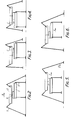
- Figure 2 shows the vehicle with all six legs on the ground with the lower body moved to the right relative to the centre body, as shown by the arrow B.
- the legs are then retracted on the upper body as shown in Figure 3 and the weight is taken on the lower legs.
- the upper and centre bodies then slide to the right on the lower body, as indicated by arrow C in Figures 3 and 4 to the position shown in Figure 4.
- the upper legs are then extended as indicated by arrow D to take the weight of the vehicle. This brings the lower legs off the ground as shown in Figure 5.
- the lower body then slides to the right in the direction of arrow E in Figures 5 and 6 to the position shown in Figure 6.
- the upper legs are then retracted so that the lower legs again contact the ground.
- the vehicle is then once again in the position shown in Figure 2 with both sets of legs on the ground but having moved in a straight line as shown by sideways movement to the right as shown in Figures 2 to 6.
- Both sets of legs may be adjustable in length. In this case when transferring the weight from one set of legs to the other set of legs there can be an indefinite period when both sets of legs are in contact with the ground.
- the weight is taken on the lower legs while the upper body is free to rotate, under control, in any direction. It could therefore for example turn 90 degrees to the right.
- the lower and centre bodies can then turn in the same direction as the upper body. This brings the bodies back in line but having turned 90 degrees in a simple move.
- rotation could be limited to just over 180 degrees in either direction to simplify the connection between the bodies such as handling of cables and wires between the bodies.
- the lower body could of course be rotated first from a position as shown in Figure 5 followed by rotation of the upper body when a position as shown in Figure 3 is reached.
- moving is carried out by relative sliding motion between the bodies.
- the movement in one direction is intermitent.
- Change in direction is achieved by rotating one body relative to the other when the weight is taken on the set of legs not connected to the body being rotated. Rotation of the other body when it is not bearing the weight of the vehicle can bring the two bodies into alignment or be used to further alter or correct the change in direction.
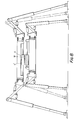
- FIG. 7 shows an eight legged vehicle with a crane jib 12.
- the structure of the vehicle can therefore be lightweight. With extended legs the vehicle would be able to stand in a reasonable depth of water and so be able to carry out dredging operations.
- two of the major advantages of such a vehicle is its ability to walk over obstacles such as walls, fences, ditches and the like and its ability to be made lightweight enabling it to be airlifted for example by helicopter. This allows it to be put close to the site of operation quickly and easily from whence it can operate. In the case of operation in difficult terrain it can thus be airlifted as close as possible before the terrain becomes unnavigatable by other means of transportation.
- the vehicle of the present invention is capable of adaption in a variety of ways for a variety of specialist usages. It may be made in many sizes and with a variety of configurations and features. A particularly lightweight vehicle may be produced using for example reinforced plastics with carbon fibre, kevlar, etc. This would give high specific strength and also good corrosion resistance.
- the vehicle may carry a set of leg extenders that could be easily attached when required. As each leg can be raised off the ground, and with lightweight construction, it would be easy to fit the extensions for operation such as in water or in water logged ground.
- a selection of removable feet could be fitted to suit the application and environment. As with the legs, it could carry a selection of feet to do different jobs.
- the feet can be rubber covered for non-slip properties and can be of large footprint for soft ground. Where digging is to be carried out forked feet may be fitted to dig into the ground to react against the forward digging forces.
- To make the vehicle more versatile it could be fitted with sensors that detect when each leg or foot touches the ground. This could conveniently be a load sensor and level or attitude sensors could also be provided. These sensors could be connected with a computer control that controls the various movements so that levelling can be provided and an even load distribution maintained.
- Extension or retraction of one or more of the legs can be effected such as when lifting or digging, so that the centre of effort of lifting, or digging, comes within the area bounded by its legs.
- One form of embodiment may provide sliding motion between the centre body and both the main legged bodies.
- the centre body may be in the form of two portions which can rotate relative to one another.
- a longer combined stride or stroke can be accomplished for given body lengths.
- a further advantage Q f this configuration would be that with one body turned at approximately 90 degrees to the other the vehicle can move in either direction with each stride.
- One convenient use of such an embodiment would be to dig a trench.
- the support legs of the lower body can be positioned to span the trench with its centre portion or slide across the trench.
- the upper body can move sideways on the lower body centre portion slide and in line with the trench on the upper body centre portion slide.
- Figure 8 shows a side view similar to Figure 1 of-an alternative embodiment.
- Two intermediate bodies 4 and 4' are provided with an interconnecting shaft 10.
- the upper intermediate body 4' is connected to the upper body 2 in a similar manner to the way in which the lower intermediate body 4 is connected to the lower body 3. This allows relative sliding motion in both the upper and lower bodies.
- Figure 9 is a view similar to Figure 1 of a three body embodiment but with the area where the intermediate body 4 joins the upper body 2 shown in cross-section.
- the embodiment shown in Figure 9 provides two further shafts or pins 10' each in its respective bore 10a allowing relative vertical motion.
- the main or control shaft 10 is in the form of a piston 30 and piston rod 40.
- the piston 10 slides in a bore in a cylinder 20 that in turn rotates within the upper body 2.
- the shafts or pins 10' are positioned either side of the piston rod 40 and these pins 10 1 slide in the bores 10a in the rotating cylinder body 20.
- Figure 10 shows one form of foot that may be used. Such a foot would conveniently be fitted to the front legs to react against horizontal forces exerted when digging, for example when digging a trench.
- the foot 9 is attached via pivot point 8 to the leg 5.
- the underside of the foot has a pin 19 which joins the foot at 21 towards the centre and is angled outwardly and downwardly.
- the pin 19 is shown having two prongs 22 in the lower plan view. In this way the foot acts as an anchor becoming more deeply entrenched and thus in deeper engagement with the ground as the leg continues to be moved in the direction of arrow B.
Abstract
A vehicle (1) comprises first and second bodies (2, 3) connected together, each body having three legs (5, 5') and the bodies are movable separately. There is a third body (4) connected to the first body (2) on a spindle 10 for relative pivotal movement and connected to the second body (3) for sliding movement. The legs are articulated at joints 7 and 8 and are adjustable in length. Each leg has a foot 9 which is replaceable. The vehicle undergoes movement or walking and the combination of sliding and pivoting allows changes in direction to be quickly and easily accomplished.
Description
- This invention relates to vehicles, more particularly to vehicles having a plurality of legs.
- Historically most vehicles have had wheels. More recent developments have been with track laying vehicles and combinations of these with wheels. Hovercraft can also be said to be a vehicle.
- All the above are limited by the type of terrain that they can negotiate. In certain conditions, a vehicle with a plurality of legs or legged vehicle that can "walk" has considerable advantages.
- Some, although not all, robots are vehicles. However, a two legged robot has to have dynamic balancing in order for it to walk and for it to have long enough legs to climb over obstacles would require a complicated system. Various multi-legged vehicles are possible, including multi-legged robots. Anything that has less than six legs is likely to require some degree of balance during moving, or "walking". A six legged vehicle is known that can move a pair of legs at a time and still be in a stable condition on the other four. Each leg can move forwards and backwards as well as having knee and hip pivot joints. Forward motion is achieved by moving the body forward with the legs swivelling backwards, then lifting successive legs and moving them forwards and placing them on the ground before doing the next body move. Changing direction is achieved by moving the legs on one side further than on the other side.
- Some sideways movements could be done by combined hip and knee joint moves with the legs on the ground and bringing them to suitable positions for the next move.
- All these movements are complicated and would require computer control in order to coordinate them with any speed and turning through 90 degrees would require a number of moves. To overcome the limitations of these conventional leg configurations and moves, the vehicle in accordance with the present invention is constructed in a different way.
- According to a first aspect of the present invention a vehicle comprises two bodies connected together, each body having three legs and the bodies being separately movable, the interconnection of the bodies providing relative rotational movement. The term vehicle as used throughout the specification and claims is to be construed broadly and includes any means of transportation, whether merely of itself or of objects other than itself. The term vehicle as used herein also includes models and toys. Movement may be self powered or controlled from outside,for example radio controlled. The rotational movement is preferably through at least 90 degrees and may be via a rotating member or shaft.
- - The vehicle may have-more than two bodies and at least two bodies have at least three legs each. The bodies are moved separately so that at any time the legs of at least one body are in contact with the ground maintaining stability. This allows the other body to be moved either laterally, vertically or in rotation with its legs temporarily not in contact with the ground. The bodies are preferably in different planes.
- Further at least one of the bodies can preferably undergo lateral movement, which movement may suitably be a sliding movement.
- - In one embodiment the bodies can undergo relative movement in a vertical plane. A further body may be provided connected to each of the other bodies.
- According to a second aspect of the present invention a vehicle comprises three bodies, the first and second bodies being interconnected to rotate relative to the third body and the second and third bodies being interconnected to move laterally with respect to the first body. Preferably all three bodies lie in different horizontal planes, the first body being the uppermost and the third body being lowermost.
- A vehicle in accordance with either aspect of the present invention preferably has at least one of the legs adjustable in length, more preferably all the legs attched to one body are adjustable in length. Thus one or both sets of legs may be adjustable in length. Such adjustment may be telescopic or by means of one or more joints.
- A working implement such as a crane, jig or digging implement maybe attached to a vehicle in accordance with the present invention.
- The invention may be put into practice in various ways but one vehicle and one modification in accordance with the present invention will now be described by way of example with reference to the accompanying drawings, in which:
- Figure 1 is a side view of a vehicle;
- Figures 2 to 6 show schematic side views similar to Figure 1 in which the vehicle is shown in a sequence of positions showing movement of the vehicle;
- Figure 7 shows a modified vehicle similar to that shown in Figures 1 to 6 but in plan from above;
- Figure 8 is a side view similar to Figure 1 of an alternative embodiment having four bodies;
- Figure 9 is a view similar to Figure 1 but in part section;-and
- Figure 10 shows one embodiment of foot that may be used.
- Figure 1 shows a
vehicle 1 having anupper body 2, alower body 3 and acentral body 4. Each of thebodies spaced legs body 2 is above thebody 3 and the legs are positioned so that each of the legs of thelower body 5' lies between the legs of theupper body 5, when viewed in plan. Each leg has an upper "hip"joint 6, a "knee" joint 7 and an articulated "foot"joint 8 to which afoot 9 is attached. - The legs can be made of many configurations with one or more joints and ability to pivot in any direction. The legs could also be telescopic in any or all their elements.
- The
upper body 2 pivots on avertical spindle 10 relative to thecentre body 4, around apivot point 11 so that when the vehicle is being supported on thelower body legs 5' theupper body legs 5 can be lifted off the ground and the upper body can then rotate in either direction on the spindle. - The
lower body 3 can slide as shown by double headed arrow A relative to the centre body. With the weight of the vehicle being taken on theupper body legs 5 thelower body 3 can move horizontally relative to the centre body. Also the centre and lower body can rotate relative to the upper body underneath the upper body. Alternatively the sliding motion could be between the upper and centre bodies with the rotation being between the centre and lower bodies. The legs may be connected to the bodies in a number of ways and a particular form of linkage is shown in Figure 1 using abracket 23 connected to the body by aspindle 24 and to the upper part of theleg 5 by apiston joint 25. Afurther piston joint 26 may be present between the upper and intermediate parts of theleg 5. - To achieve "walking" in any direction, there needs to be some relative vertical motion to allow the legs on the upper body to take the weight and then have the legs on the lower body to take the weight. This can be done in a number of ways. Three possible ways are:-
- 1. Vertical motions of the legs using joints, for example "knee" joints or equivalents.
- 2. Telescopic motions of one or both sets of legs.
- 3. Vertical slide motion built into the rotation between the upper and centre bodies.
- Any combination of these could also be used.
- Movement of the vehicle will now be described with reference to Figures 2 to 6. The terms upper, lower, right, left, horizontal, vertical and the like as used throughout the specification including the claims are relative terms and not to be construed as in any way limiting. In the embodiment shown in Figures 2 to 6 there are three
fixed legs 5' on thelower body 3 and threeextendable legs 5 on theupper body 2. Movement or "walking" in a straight line from left to right will now be described. - Figure 2 shows the vehicle with all six legs on the ground with the lower body moved to the right relative to the centre body, as shown by the arrow B. The legs are then retracted on the upper body as shown in Figure 3 and the weight is taken on the lower legs. The upper and centre bodies then slide to the right on the lower body, as indicated by arrow C in Figures 3 and 4 to the position shown in Figure 4. The upper legs are then extended as indicated by arrow D to take the weight of the vehicle. This brings the lower legs off the ground as shown in Figure 5.
- The lower body then slides to the right in the direction of arrow E in Figures 5 and 6 to the position shown in Figure 6. The upper legs are then retracted so that the lower legs again contact the ground. The vehicle is then once again in the position shown in Figure 2 with both sets of legs on the ground but having moved in a straight line as shown by sideways movement to the right as shown in Figures 2 to 6.
- Both sets of legs may be adjustable in length. In this case when transferring the weight from one set of legs to the other set of legs there can be an indefinite period when both sets of legs are in contact with the ground.
- When either or both sets of legs are adjustable in length there may also or instead be relative vertical movement of the bodies with respect to each other.
- Movement giving a change of direction will now be described starting from the position shown in Figure 3.
- The weight is taken on the lower legs while the upper body is free to rotate, under control, in any direction. It could therefore for example turn 90 degrees to the right. In the position shown in Figure 5 with the weight on the upper body legs, the lower and centre bodies can then turn in the same direction as the upper body. This brings the bodies back in line but having turned 90 degrees in a simple move.
- In practice the rotation could be limited to just over 180 degrees in either direction to simplify the connection between the bodies such as handling of cables and wires between the bodies.
- The lower body could of course be rotated first from a position as shown in Figure 5 followed by rotation of the upper body when a position as shown in Figure 3 is reached. In the embodiment described moving is carried out by relative sliding motion between the bodies. The movement in one direction is intermitent. Change in direction is achieved by rotating one body relative to the other when the weight is taken on the set of legs not connected to the body being rotated. Rotation of the other body when it is not bearing the weight of the vehicle can bring the two bodies into alignment or be used to further alter or correct the change in direction.
- There are numerous applications for such a vehicle including: lifting, digging, dredging, transport of personnel and objects such as over difficult terrain, whether self propelled or controlled remotely, and recreation, such as obstacle racing.
- Most vehicles that are used for lifting such as mobile cranes, or for digging, such as tractors, rely on substantial counterbalancing weight to offset the load on the crane or shovel. This is not the case with a vehicle according to the present invention. Figure 7 shows an eight legged vehicle with a
crane jib 12. By having at least two of thelegs jib 12 all the weight of the lift will be taken by the legs without the need of heavy counterbalance. The structure of the vehicle can therefore be lightweight. With extended legs the vehicle would be able to stand in a reasonable depth of water and so be able to carry out dredging operations. - Further, two of the major advantages of such a vehicle is its ability to walk over obstacles such as walls, fences, ditches and the like and its ability to be made lightweight enabling it to be airlifted for example by helicopter. This allows it to be put close to the site of operation quickly and easily from whence it can operate. In the case of operation in difficult terrain it can thus be airlifted as close as possible before the terrain becomes unnavigatable by other means of transportation.
- As with most vehicles it would be possible to use a vehicle according to the present invention in competetive sport, such as over obstacle course trials or racing.
- The vehicle of the present invention is capable of adaption in a variety of ways for a variety of specialist usages. It may be made in many sizes and with a variety of configurations and features. A particularly lightweight vehicle may be produced using for example reinforced plastics with carbon fibre, kevlar, etc. This would give high specific strength and also good corrosion resistance.
- _ The vehicle may carry a set of leg extenders that could be easily attached when required. As each leg can be raised off the ground, and with lightweight construction, it would be easy to fit the extensions for operation such as in water or in water logged ground. A selection of removable feet could be fitted to suit the application and environment. As with the legs, it could carry a selection of feet to do different jobs. The feet can be rubber covered for non-slip properties and can be of large footprint for soft ground. Where digging is to be carried out forked feet may be fitted to dig into the ground to react against the forward digging forces. To make the vehicle more versatile it could be fitted with sensors that detect when each leg or foot touches the ground. This could conveniently be a load sensor and level or attitude sensors could also be provided. These sensors could be connected with a computer control that controls the various movements so that levelling can be provided and an even load distribution maintained.
- Extension or retraction of one or more of the legs can be effected such as when lifting or digging, so that the centre of effort of lifting, or digging, comes within the area bounded by its legs.
- One form of embodiment may provide sliding motion between the centre body and both the main legged bodies. The centre body may be in the form of two portions which can rotate relative to one another. By providing for sliding movement with respect to both the main legged bodies so that the first portion of the centre body slides with respect to the first main body and the second portion of the centre body slides with respect to the second main body a longer combined stride or stroke can be accomplished for given body lengths. A further advantage Qf this configuration would be that with one body turned at approximately 90 degrees to the other the vehicle can move in either direction with each stride. One convenient use of such an embodiment would be to dig a trench. The support legs of the lower body can be positioned to span the trench with its centre portion or slide across the trench. The upper body can move sideways on the lower body centre portion slide and in line with the trench on the upper body centre portion slide.
- Figure 8 shows a side view similar to Figure 1 of-an alternative embodiment. In this case there are four bodies. Two
intermediate bodies 4 and 4' are provided with an interconnectingshaft 10. The upper intermediate body 4' is connected to theupper body 2 in a similar manner to the way in which the lowerintermediate body 4 is connected to thelower body 3. This allows relative sliding motion in both the upper and lower bodies. - Figure 9 is a view similar to Figure 1 of a three body embodiment but with the area where the
intermediate body 4 joins theupper body 2 shown in cross-section. The embodiment shown in Figure 9 provides two further shafts or pins 10' each in itsrespective bore 10a allowing relative vertical motion. The main orcontrol shaft 10 is in the form of apiston 30 andpiston rod 40. Thepiston 10 slides in a bore in acylinder 20 that in turn rotates within theupper body 2. The shafts or pins 10' are positioned either side of thepiston rod 40 and thesepins 101 slide in thebores 10a in therotating cylinder body 20. - Figure 10 shows one form of foot that may be used. Such a foot would conveniently be fitted to the front legs to react against horizontal forces exerted when digging, for example when digging a trench. The
foot 9 is attached viapivot point 8 to theleg 5. The underside of the foot has apin 19 which joins the foot at 21 towards the centre and is angled outwardly and downwardly. Thepin 19 is shown having twoprongs 22 in the lower plan view. In this way the foot acts as an anchor becoming more deeply entrenched and thus in deeper engagement with the ground as the leg continues to be moved in the direction of arrow B.
Claims (10)
1. A vehicle comprising two bodies connected together, each body having three legs and the bodies being separately movable, the interconnection of the bodies providing relative rotational movement.
2. A vehicle as claimed in Claim 1 in which the bodies are in different planes.
3. A vehicle as claimed in any of the preceding claims in which at least one of the bodies can undergo lateral movement.
4. A vehicle as claimed in Claim 3 in which the lateral movement is a sliding movement.
5. A vehicle as claimed in any one of the preceding claims in which at least one of the bodies can undergo relative movement in a vertical plane.
6. A vehicle as claimed in any one of the preceding claims in which there is a third body connected to each of the other bodies.
7. A vehicle comprising three bodies, the first and second bodies being interconnected to rotate relative to the third body and the second and third bodies being interconnected to move laterally with respect to the first body.
8. A vehicle as claimed in Claim 6 or 7 in which the third body comprises two portions each portion being movable relative to one of the first and second bodies and the two portions being movable relative to one another.
9. A vehicle as claimed in Claim 8 in which the relative movement of each portion of the third body with respect to the first and second bodies is a sliding movement and the two portions of the third body are rotatable relative to one another.
10. A vehicle as claimed in Claim 7,8 or 9 in which all three bodies lie in different horizontal planes, the first body being the uppermost and the third body being lowermost.
Applications Claiming Priority (2)
| Application Number | Priority Date | Filing Date | Title |
|---|---|---|---|
| GB8408458 | 1984-04-02 | ||
| GB848408458A GB8408458D0 (en) | 1984-04-02 | 1984-04-02 | Vehicle |
Publications (2)
| Publication Number | Publication Date |
|---|---|
| EP0157633A2 true EP0157633A2 (en) | 1985-10-09 |
| EP0157633A3 EP0157633A3 (en) | 1986-05-14 |
Family
ID=10559039
Family Applications (1)
| Application Number | Title | Priority Date | Filing Date |
|---|---|---|---|
| EP85302309A Withdrawn EP0157633A3 (en) | 1984-04-02 | 1985-04-02 | Vehicle |
Country Status (4)
| Country | Link |
|---|---|
| US (1) | US4662465A (en) |
| EP (1) | EP0157633A3 (en) |
| JP (1) | JPS60255581A (en) |
| GB (1) | GB8408458D0 (en) |
Cited By (11)
| Publication number | Priority date | Publication date | Assignee | Title |
|---|---|---|---|---|
| EP0257791A1 (en) * | 1986-07-24 | 1988-03-02 | Eric Sheeter | A vehicle |
| FR2607093A1 (en) * | 1986-11-21 | 1988-05-27 | Commissariat Energie Atomique | Vehicle capable of moving over a surface of any orientation |
| EP0389243A2 (en) * | 1989-03-21 | 1990-09-26 | Portsmouth Technology Consultants Limited | Robot devices |
| EP0399720A1 (en) * | 1989-05-17 | 1990-11-28 | Carnegie-Mellon University | Orthogonal legged walking robot |
| EP0401120A1 (en) * | 1989-06-02 | 1990-12-05 | Bouygues | Remote-controlled mobile robot for working surfaces, particularly for cleaning glass-walls |
| DE19637501A1 (en) * | 1996-09-13 | 1998-03-26 | Schlattmann Josef Prof H C Dr | Mobile machine or walking robot |
| EP2172390A1 (en) * | 2008-10-06 | 2010-04-07 | Niederberger Engineering AG | Mobile climbing robot and service system with climbing robot |
| WO2010142277A1 (en) * | 2009-06-12 | 2010-12-16 | Steinke Technikus Gmbh | Transport means, in particular for physically disabled people |
| WO2013007975A1 (en) * | 2011-07-14 | 2013-01-17 | Aquamarine Power Limited | An underwater vehicle for installation, maintenance of wave, tidal or water current power generating devices |
| CN105292298A (en) * | 2015-12-04 | 2016-02-03 | 哈尔滨工业大学 | Three-section machine body type hexapod robot with transportation function and operation function fused |
| CN107200078A (en) * | 2017-05-17 | 2017-09-26 | 上海大学 | A kind of link-type multi-foot robot |
Families Citing this family (48)
| Publication number | Priority date | Publication date | Assignee | Title |
|---|---|---|---|---|
| JPH0725338B2 (en) * | 1985-06-28 | 1995-03-22 | 株式会社小松製作所 | Walker |
| JPS63150176A (en) * | 1986-12-15 | 1988-06-22 | 工業技術院長 | Walking control method of dynamic walking robot |
| US4862980A (en) * | 1988-10-06 | 1989-09-05 | Quest Systems, Inc. | Walking machine |
| US5127484A (en) * | 1988-12-22 | 1992-07-07 | Carnegie-Mellon University | Orthogonal legged walking robot |
| US5005658A (en) * | 1988-12-22 | 1991-04-09 | Carnegie-Mellon University | Orthogonal legged walking robot |
| DE4239987C2 (en) * | 1992-11-27 | 1996-07-11 | Siemens Ag | Self-moving unit for movement between opposing wall surfaces |
| JP3277076B2 (en) * | 1994-09-09 | 2002-04-22 | 株式会社小松製作所 | Walking control device and walking control method for walking robot |
| JP2560264B2 (en) * | 1994-12-02 | 1996-12-04 | 工業技術院長 | Multi-legged walking device |
| IT1273858B (en) * | 1994-12-22 | 1997-07-11 | Giancarlo Zamagni | ANTHROPOD LOCOMATION MACHINE ON A SUPERFCIE |
| US6109378A (en) * | 1995-11-06 | 2000-08-29 | Plustech Oy | Leg mechanism |
| US6068073A (en) * | 1996-05-10 | 2000-05-30 | Cybernet Systems Corporation | Transformable mobile robot |
| FI100873B (en) | 1996-09-25 | 1998-03-13 | Plustech Oy | Actuators for effecting the pivotal movement of a pivot arm |
| IL124413A (en) * | 1998-05-11 | 2001-05-20 | Friendly Robotics Ltd | System and method for area coverage with an autonomous robot |
| US6308791B1 (en) * | 1999-05-06 | 2001-10-30 | Sandia Corporation | Steerable vertical to horizontal energy transducer for mobile robots |
| US6481513B2 (en) | 2000-03-16 | 2002-11-19 | Mcgill University | Single actuator per leg robotic hexapod |
| JP4480843B2 (en) * | 2000-04-03 | 2010-06-16 | ソニー株式会社 | Legged mobile robot, control method therefor, and relative movement measurement sensor for legged mobile robot |
| NL1015764C2 (en) * | 2000-07-20 | 2002-01-22 | Seumeren Holland B V Van | Crane. |
| IL138695A (en) * | 2000-09-26 | 2004-08-31 | Rafael Armament Dev Authority | Unmanned mobile device |
| IL141300A0 (en) | 2001-02-07 | 2002-03-10 | Kandelshein Menachem | A method and apparatus for flat surface treatment |
| KR100487449B1 (en) * | 2001-08-31 | 2005-05-04 | 창원대학교 산학협력단 | Walking robot to carry heavy weight |
| US6866557B2 (en) * | 2002-07-02 | 2005-03-15 | Mitch Randall | Apparatus and method for producing ambulatory motion |
| US7314343B2 (en) * | 2002-07-22 | 2008-01-01 | Westinghouse Electric Co. Llc | Miniature manipulator for servicing the interior of nuclear steam generator tubes |
| US7603199B2 (en) * | 2003-11-27 | 2009-10-13 | Honda Motor Co., Ltd. | Control device for mobile body |
| US7734375B2 (en) * | 2004-06-09 | 2010-06-08 | Boston Dynamics | Robot and robot leg mechanism |
| US7878276B2 (en) * | 2005-07-08 | 2011-02-01 | H. Phillip Limbacher, Jr. | Ambulatory vehicle |
| US7604075B1 (en) | 2005-07-08 | 2009-10-20 | Limbacher Jr H Phillip | Ambulatory vehicle |
| US7803031B1 (en) | 2005-11-03 | 2010-09-28 | Winckler Jason M | Vehicle having non-circular wheels propelled by a moving weight |
| US20080296853A1 (en) * | 2007-06-01 | 2008-12-04 | Langford Christopher J | Stair assist robot mechanism and method |
| US8127871B2 (en) * | 2008-11-03 | 2012-03-06 | Robert J Viola | Frame walker predicated on a parallel mechanism |
| WO2011085137A1 (en) * | 2010-01-06 | 2011-07-14 | Mitch Randall | Improved method and apparatus for producing ambulatory motion |
| US8657042B2 (en) * | 2010-10-04 | 2014-02-25 | China Industries Limited | Walking machine |
| CN102050309A (en) * | 2010-12-06 | 2011-05-11 | 黎志中 | Conveyor in mountainous region |
| RU2479692C1 (en) * | 2011-11-29 | 2013-04-20 | Марина Георгиевна Сафонова | Simplest undercarriage |
| RU2485250C1 (en) * | 2011-12-30 | 2013-06-20 | Марина Георгиевна Сафонова | Multipurpose dozer excavator |
| DE102013104166B4 (en) | 2013-04-24 | 2016-06-09 | Tino Werner | Walking robot with improved mechanics |
| WO2014174487A2 (en) | 2013-04-24 | 2014-10-30 | Tino Werner | Improved walking robot |
| DE102013104578B3 (en) * | 2013-05-03 | 2014-04-30 | Tino Werner | Collision hazard detection controller for motors of mobile robot, has sensors arranged at different locations on periphery of robot such that combined output signals of sensors are used as input signals for transistors and amplifiers |
| CN103693124B (en) * | 2013-05-24 | 2016-01-20 | 北京航空航天大学 | A kind of Transformable spherical robot |
| US20150101322A1 (en) * | 2013-10-14 | 2015-04-16 | Brian Riskas | System architecture for mobile hydraulic equipment |
| US9073588B1 (en) * | 2014-06-05 | 2015-07-07 | Orion Drilling Company | Heavy machinery substructure for traversing and working over ground obstructions |
| US9381961B1 (en) * | 2014-09-04 | 2016-07-05 | Google Inc. | Robotic systems having protrusions for use in starting positions and in use positions |
| GB201504846D0 (en) * | 2015-03-23 | 2015-05-06 | Rolls Royce Plc | Machine tools |
| US10189519B2 (en) * | 2015-05-29 | 2019-01-29 | Oregon State University | Leg configuration for spring-mass legged locomotion |
| US10011311B2 (en) * | 2015-08-28 | 2018-07-03 | Herbert Russell Burnham | Quadra walker |
| CN106741287B (en) * | 2017-01-17 | 2018-10-12 | 北京交通大学 | A kind of bipod walking robot mechanism with leg structure in parallel |
| US10719085B2 (en) * | 2018-02-22 | 2020-07-21 | Boston Dynamics, Inc. | Mobile robot sitting and standing |
| DE102019134060A1 (en) | 2019-01-18 | 2020-07-23 | Macaso Gmbh | Device for the positive guidance of tools on flat or slightly curved, arbitrarily oriented component surfaces |
| CN112441156B (en) * | 2019-08-29 | 2021-11-30 | 南京禹智智能科技有限公司 | Leg and foot mechanism of high-performance bionic foot type robot |
Citations (7)
| Publication number | Priority date | Publication date | Assignee | Title |
|---|---|---|---|---|
| DE1013227B (en) * | 1953-09-19 | 1957-08-01 | Orenstein & Koppel Ag | Track skid for large devices |
| GB882911A (en) * | 1958-05-05 | 1961-11-22 | Bade & Co Gmbh | Gear for moving heavy rigs over open ground |
| US3331463A (en) * | 1964-12-14 | 1967-07-18 | Lyle L Kramer | Motor operated ambulatory vehicle |
| EP0010034A1 (en) * | 1978-09-29 | 1980-04-16 | COMMISSARIAT A L'ENERGIE ATOMIQUE Etablissement de Caractère Scientifique Technique et Industriel | Vehicle able to propel itself with adhesion over any surface |
| US4202423A (en) * | 1978-04-20 | 1980-05-13 | Soto Jose M | Land vehicle with articulated legs |
| EP0084012A1 (en) * | 1982-01-11 | 1983-07-20 | International Robotic Engineering Inc. | Robot with climbing members |
| FR2553368A1 (en) * | 1983-10-13 | 1985-04-19 | Hubschen Alfred | Transport apparatus |
Family Cites Families (12)
| Publication number | Priority date | Publication date | Assignee | Title |
|---|---|---|---|---|
| GB881911A (en) * | 1958-10-22 | 1961-11-08 | Int Computers & Tabulators Ltd | Improvements in or relating to statistical record reading devices |
| US3002578A (en) * | 1958-12-05 | 1961-10-03 | Kraus Hans Wilhelm | Control means for a conveyance |
| GB952584A (en) * | 1960-03-23 | 1964-03-18 | Weserhuette Ag Eisenwerk | Improvements in or relating to walking mechanisms for moving heavy loads |
| FR84012E (en) * | 1963-04-19 | 1964-11-13 | Chaffoteaux Et Maury | Improvements to hot water heating systems |
| US3734220A (en) * | 1972-01-07 | 1973-05-22 | R Smith | Self-propelled platform tower having mechanical and hydraulic supporting means |
| SU692948A1 (en) * | 1972-09-28 | 1979-10-25 | Государственный Научно-Исследовательский И Проектный Институт Угольной Промышленности /Укр Ниипроект/ | Stepping undercarriage of mining machines |
| DE2506313C3 (en) * | 1974-02-19 | 1979-07-12 | Vsesojuznyj Nautschno-Issledovatelskij I Proektno-Konstruktorskij Institut Soloto-Platinovoj, Almaznoj I Volframo- Molibdenovoj Promyschlennosti Vnii Prozoloto, Moskau | Method for moving devices provided with extraction or investigation devices on the bottom of inland waters and seas and device for carrying out this method |
| SU823212A1 (en) * | 1978-11-29 | 1981-04-23 | Semenov Rudolf M | Walking propelling gear |
| JPS5631879A (en) * | 1979-08-23 | 1981-03-31 | Fuji Electric Co Ltd | Self-motive transport vehicle |
| US4527650A (en) * | 1983-03-18 | 1985-07-09 | Odetics, Inc. | Walking machine |
| US4502556A (en) * | 1983-03-18 | 1985-03-05 | Odetics, Inc. | Vertical actuator mechanism for the legs of a walking machine |
| US4558758A (en) * | 1983-12-02 | 1985-12-17 | Erwin Littman | Prime mover |
-
1984
- 1984-04-02 GB GB848408458A patent/GB8408458D0/en active Pending
-
1985
- 1985-04-02 US US06/718,990 patent/US4662465A/en not_active Expired - Fee Related
- 1985-04-02 EP EP85302309A patent/EP0157633A3/en not_active Withdrawn
- 1985-04-02 JP JP60069870A patent/JPS60255581A/en active Pending
Patent Citations (7)
| Publication number | Priority date | Publication date | Assignee | Title |
|---|---|---|---|---|
| DE1013227B (en) * | 1953-09-19 | 1957-08-01 | Orenstein & Koppel Ag | Track skid for large devices |
| GB882911A (en) * | 1958-05-05 | 1961-11-22 | Bade & Co Gmbh | Gear for moving heavy rigs over open ground |
| US3331463A (en) * | 1964-12-14 | 1967-07-18 | Lyle L Kramer | Motor operated ambulatory vehicle |
| US4202423A (en) * | 1978-04-20 | 1980-05-13 | Soto Jose M | Land vehicle with articulated legs |
| EP0010034A1 (en) * | 1978-09-29 | 1980-04-16 | COMMISSARIAT A L'ENERGIE ATOMIQUE Etablissement de Caractère Scientifique Technique et Industriel | Vehicle able to propel itself with adhesion over any surface |
| EP0084012A1 (en) * | 1982-01-11 | 1983-07-20 | International Robotic Engineering Inc. | Robot with climbing members |
| FR2553368A1 (en) * | 1983-10-13 | 1985-04-19 | Hubschen Alfred | Transport apparatus |
Cited By (19)
| Publication number | Priority date | Publication date | Assignee | Title |
|---|---|---|---|---|
| EP0257791A1 (en) * | 1986-07-24 | 1988-03-02 | Eric Sheeter | A vehicle |
| FR2607093A1 (en) * | 1986-11-21 | 1988-05-27 | Commissariat Energie Atomique | Vehicle capable of moving over a surface of any orientation |
| EP0389243A2 (en) * | 1989-03-21 | 1990-09-26 | Portsmouth Technology Consultants Limited | Robot devices |
| EP0389243A3 (en) * | 1989-03-21 | 1991-11-27 | Portsmouth Technology Consultants Limited | Robot devices |
| US5121805A (en) * | 1989-03-21 | 1992-06-16 | Portsmouth Technology Consultants Limited | Robot devices |
| EP0399720A1 (en) * | 1989-05-17 | 1990-11-28 | Carnegie-Mellon University | Orthogonal legged walking robot |
| EP0401120A1 (en) * | 1989-06-02 | 1990-12-05 | Bouygues | Remote-controlled mobile robot for working surfaces, particularly for cleaning glass-walls |
| FR2647840A1 (en) * | 1989-06-02 | 1990-12-07 | Bouygues Sa | VENTOUS DEVICE FOR CARRYING AND MOVING A MEANS OF INTERVENTION ON A SURFACE, IN PARTICULAR ON A BUILDING FACADE |
| DE19637501A1 (en) * | 1996-09-13 | 1998-03-26 | Schlattmann Josef Prof H C Dr | Mobile machine or walking robot |
| DE19637501C2 (en) * | 1996-09-13 | 2000-07-13 | Josef Schlattmann | Walking machine and method for controlling a walking machine |
| EP2172390A1 (en) * | 2008-10-06 | 2010-04-07 | Niederberger Engineering AG | Mobile climbing robot and service system with climbing robot |
| WO2010040240A1 (en) * | 2008-10-06 | 2010-04-15 | Niederberger Engineering Ag | Mobile climbing robot and service system having a climbing robot |
| US8534395B2 (en) | 2008-10-06 | 2013-09-17 | Niederberger Engineering Ag | Mobile climbing robot and service system having a climbing robot |
| WO2010142277A1 (en) * | 2009-06-12 | 2010-12-16 | Steinke Technikus Gmbh | Transport means, in particular for physically disabled people |
| WO2013007975A1 (en) * | 2011-07-14 | 2013-01-17 | Aquamarine Power Limited | An underwater vehicle for installation, maintenance of wave, tidal or water current power generating devices |
| CN105292298A (en) * | 2015-12-04 | 2016-02-03 | 哈尔滨工业大学 | Three-section machine body type hexapod robot with transportation function and operation function fused |
| CN105292298B (en) * | 2015-12-04 | 2018-06-08 | 哈尔滨工业大学 | It is a kind of to merge transport and three sections of body formula Hexapod Robots of operation function |
| CN107200078A (en) * | 2017-05-17 | 2017-09-26 | 上海大学 | A kind of link-type multi-foot robot |
| CN107200078B (en) * | 2017-05-17 | 2019-04-23 | 上海大学 | A kind of link-type multi-foot robot |
Also Published As
| Publication number | Publication date |
|---|---|
| EP0157633A3 (en) | 1986-05-14 |
| JPS60255581A (en) | 1985-12-17 |
| GB8408458D0 (en) | 1984-05-10 |
| US4662465A (en) | 1987-05-05 |
Similar Documents
| Publication | Publication Date | Title |
|---|---|---|
| US4662465A (en) | Walking vehicle | |
| US4790400A (en) | Stepping vehicle | |
| US6364040B1 (en) | Walking device | |
| US5739655A (en) | Ambulatory robot and ambulation control method for same | |
| US4265326A (en) | Rolling and stepping vehicle | |
| US4266627A (en) | Traveling assembly and wheel suspension for a rolling and stepping vehicle | |
| US6478314B1 (en) | Walking device | |
| CN111976859B (en) | UPS-based parallel-connection wheel-foot mobile robot | |
| CN105292298B (en) | It is a kind of to merge transport and three sections of body formula Hexapod Robots of operation function | |
| Adachi et al. | Mechanism and control of a leg-wheel hybrid mobile robot | |
| CN103273985B (en) | Quadruped stair climbing robot mechanism | |
| CN105599818B (en) | Barrier-surpassing robot | |
| CN105857432A (en) | Hexapod robot, foot control method and gait control method | |
| CN105151153A (en) | Wheel-foot hybrid mode hexapod robot moving platform | |
| CN113306352B (en) | Multi-terrain adaptive amphibious six-foot belt waist multifunctional robot | |
| CN110682976A (en) | Multi-degree-of-freedom mechanical wheel leg structure of wheel leg combined type mobile robot | |
| CN205273662U (en) | For military use bionical operation robot based on bionics principle | |
| CA1267668A (en) | Cross-country vehicle | |
| US4147218A (en) | Bulldozer attachment for four-tracked tractor | |
| KR102180791B1 (en) | Multi-joint Walking Robot With Six Legs and Its Control Method | |
| Suwannasit et al. | A bio-inspired hybrid leg-wheel robot | |
| KR100487449B1 (en) | Walking robot to carry heavy weight | |
| CN219096869U (en) | Mountain walking chassis and mountain walking robot | |
| KR20220015817A (en) | Leg module for walking robot | |
| CN219904571U (en) | Caterpillar foot combined type hexapod robot |
Legal Events
| Date | Code | Title | Description |
|---|---|---|---|
| PUAI | Public reference made under article 153(3) epc to a published international application that has entered the european phase |
Free format text: ORIGINAL CODE: 0009012 |
|
| AK | Designated contracting states |
Designated state(s): AT BE CH DE FR GB IT LI LU NL SE |
|
| PUAL | Search report despatched |
Free format text: ORIGINAL CODE: 0009013 |
|
| AK | Designated contracting states |
Kind code of ref document: A3 Designated state(s): AT BE CH DE FR GB IT LI LU NL SE |
|
| 17P | Request for examination filed |
Effective date: 19861103 |
|
| 17Q | First examination report despatched |
Effective date: 19870605 |
|
| STAA | Information on the status of an ep patent application or granted ep patent |
Free format text: STATUS: THE APPLICATION IS DEEMED TO BE WITHDRAWN |
|
| 18D | Application deemed to be withdrawn |
Effective date: 19871216 |