EP0153110A2 - Capillary transport device having speed and meniscus control means, and method of using - Google Patents
Capillary transport device having speed and meniscus control means, and method of using Download PDFInfo
- Publication number
- EP0153110A2 EP0153110A2 EP85300862A EP85300862A EP0153110A2 EP 0153110 A2 EP0153110 A2 EP 0153110A2 EP 85300862 A EP85300862 A EP 85300862A EP 85300862 A EP85300862 A EP 85300862A EP 0153110 A2 EP0153110 A2 EP 0153110A2
- Authority
- EP
- European Patent Office
- Prior art keywords
- liquid
- zone
- flow
- liquids
- barriers
- Prior art date
- Legal status (The legal status is an assumption and is not a legal conclusion. Google has not performed a legal analysis and makes no representation as to the accuracy of the status listed.)
- Granted
Links
Images


Classifications
-
- B—PERFORMING OPERATIONS; TRANSPORTING
- B01—PHYSICAL OR CHEMICAL PROCESSES OR APPARATUS IN GENERAL
- B01L—CHEMICAL OR PHYSICAL LABORATORY APPARATUS FOR GENERAL USE
- B01L3/00—Containers or dishes for laboratory use, e.g. laboratory glassware; Droppers
- B01L3/50—Containers for the purpose of retaining a material to be analysed, e.g. test tubes
- B01L3/502—Containers for the purpose of retaining a material to be analysed, e.g. test tubes with fluid transport, e.g. in multi-compartment structures
- B01L3/5027—Containers for the purpose of retaining a material to be analysed, e.g. test tubes with fluid transport, e.g. in multi-compartment structures by integrated microfluidic structures, i.e. dimensions of channels and chambers are such that surface tension forces are important, e.g. lab-on-a-chip
- B01L3/502738—Containers for the purpose of retaining a material to be analysed, e.g. test tubes with fluid transport, e.g. in multi-compartment structures by integrated microfluidic structures, i.e. dimensions of channels and chambers are such that surface tension forces are important, e.g. lab-on-a-chip characterised by integrated valves
-
- B—PERFORMING OPERATIONS; TRANSPORTING
- B01—PHYSICAL OR CHEMICAL PROCESSES OR APPARATUS IN GENERAL
- B01L—CHEMICAL OR PHYSICAL LABORATORY APPARATUS FOR GENERAL USE
- B01L3/00—Containers or dishes for laboratory use, e.g. laboratory glassware; Droppers
- B01L3/50—Containers for the purpose of retaining a material to be analysed, e.g. test tubes
- B01L3/502—Containers for the purpose of retaining a material to be analysed, e.g. test tubes with fluid transport, e.g. in multi-compartment structures
- B01L3/5027—Containers for the purpose of retaining a material to be analysed, e.g. test tubes with fluid transport, e.g. in multi-compartment structures by integrated microfluidic structures, i.e. dimensions of channels and chambers are such that surface tension forces are important, e.g. lab-on-a-chip
- B01L3/502746—Containers for the purpose of retaining a material to be analysed, e.g. test tubes with fluid transport, e.g. in multi-compartment structures by integrated microfluidic structures, i.e. dimensions of channels and chambers are such that surface tension forces are important, e.g. lab-on-a-chip characterised by the means for controlling flow resistance, e.g. flow controllers, baffles
-
- B—PERFORMING OPERATIONS; TRANSPORTING
- B01—PHYSICAL OR CHEMICAL PROCESSES OR APPARATUS IN GENERAL
- B01L—CHEMICAL OR PHYSICAL LABORATORY APPARATUS FOR GENERAL USE
- B01L2200/00—Solutions for specific problems relating to chemical or physical laboratory apparatus
- B01L2200/06—Fluid handling related problems
- B01L2200/0684—Venting, avoiding backpressure, avoid gas bubbles
-
- B—PERFORMING OPERATIONS; TRANSPORTING
- B01—PHYSICAL OR CHEMICAL PROCESSES OR APPARATUS IN GENERAL
- B01L—CHEMICAL OR PHYSICAL LABORATORY APPARATUS FOR GENERAL USE
- B01L2300/00—Additional constructional details
- B01L2300/06—Auxiliary integrated devices, integrated components
- B01L2300/0627—Sensor or part of a sensor is integrated
- B01L2300/0645—Electrodes
-
- B—PERFORMING OPERATIONS; TRANSPORTING
- B01—PHYSICAL OR CHEMICAL PROCESSES OR APPARATUS IN GENERAL
- B01L—CHEMICAL OR PHYSICAL LABORATORY APPARATUS FOR GENERAL USE
- B01L2300/00—Additional constructional details
- B01L2300/08—Geometry, shape and general structure
- B01L2300/0809—Geometry, shape and general structure rectangular shaped
- B01L2300/0825—Test strips
-
- B—PERFORMING OPERATIONS; TRANSPORTING
- B01—PHYSICAL OR CHEMICAL PROCESSES OR APPARATUS IN GENERAL
- B01L—CHEMICAL OR PHYSICAL LABORATORY APPARATUS FOR GENERAL USE
- B01L2300/00—Additional constructional details
- B01L2300/08—Geometry, shape and general structure
- B01L2300/0861—Configuration of multiple channels and/or chambers in a single devices
- B01L2300/0867—Multiple inlets and one sample wells, e.g. mixing, dilution
-
- B—PERFORMING OPERATIONS; TRANSPORTING
- B01—PHYSICAL OR CHEMICAL PROCESSES OR APPARATUS IN GENERAL
- B01L—CHEMICAL OR PHYSICAL LABORATORY APPARATUS FOR GENERAL USE
- B01L2400/00—Moving or stopping fluids
- B01L2400/04—Moving fluids with specific forces or mechanical means
- B01L2400/0403—Moving fluids with specific forces or mechanical means specific forces
- B01L2400/0406—Moving fluids with specific forces or mechanical means specific forces capillary forces
-
- B—PERFORMING OPERATIONS; TRANSPORTING
- B01—PHYSICAL OR CHEMICAL PROCESSES OR APPARATUS IN GENERAL
- B01L—CHEMICAL OR PHYSICAL LABORATORY APPARATUS FOR GENERAL USE
- B01L2400/00—Moving or stopping fluids
- B01L2400/08—Regulating or influencing the flow resistance
- B01L2400/084—Passive control of flow resistance
- B01L2400/086—Passive control of flow resistance using baffles or other fixed flow obstructions
-
- Y—GENERAL TAGGING OF NEW TECHNOLOGICAL DEVELOPMENTS; GENERAL TAGGING OF CROSS-SECTIONAL TECHNOLOGIES SPANNING OVER SEVERAL SECTIONS OF THE IPC; TECHNICAL SUBJECTS COVERED BY FORMER USPC CROSS-REFERENCE ART COLLECTIONS [XRACs] AND DIGESTS
- Y10—TECHNICAL SUBJECTS COVERED BY FORMER USPC
- Y10S—TECHNICAL SUBJECTS COVERED BY FORMER USPC CROSS-REFERENCE ART COLLECTIONS [XRACs] AND DIGESTS
- Y10S366/00—Agitating
- Y10S366/03—Micromixers: variable geometry from the pathway influences mixing/agitation of non-laminar fluid flow
Definitions
- This invention is directed to a device and a method for transporting liquid by capillary attraction between two opposing surfaces.
- two liquids can be brought together by flowing in opposing directions, creating a flow in opposition, or they can be transported in a concurrent flow wherein they advance simultaneously and together through the same part of the zone.
- the intent can be to have only one of the two liquids in any one of two parts of the zone, the liquids meeting at a junction between the two parts.
- the intent can be for each of the liquids to traverse essentially all of the transport zone, arriving in generally equal amounts at a final destination.
- ISE ion-selective electrodes
- two liquids are introduced into the spacing between the surfaces to advance in opposite directions ideally at equal rates to meet at a predetermined junction, as explained, for example, in U.S. Patent No. 4,271,119, issued on June 2, 1981.
- ISE ion-selective electrodes
- a liquid transport device is known in accordance with the prior art portion of claim 1 hereinafter set forth.
- the ribs of such known device are provided on both of the opposed capillary surfaces. It is desirable at least from the standpoint of production to provide controlled flow wherein at least one of the opposing capillary surfaces is left generally smooth. Prior to this invention, it has not been clear how this could be done and still avoid air entrapment.
- the problem of the invention has been to mechanically control the liquid flow in a capillary transport zone, without air entrapment, by a construction that allows the use of a generally smooth surface as one of the capillary-defining surfaces, thus simplifying production.
- This problem is solved with a liquid transport device having two opposed surfaces spaced apart a distance effective to induce capillary flow between the surfaces of introduced liquid and thus provide a capillary zone, and access means for admitting liquids to the zone.
- One of the surfaces of this device includes spaced-apart energy barriers which a) extend across a portion of the primary direction of travel of liquid through the zone, and b) have a height less than the distance between the surfaces; characterized in that at least every other one of the barriers includes slot means for preventing air entrapment between the energy barriers; and the other of the surfaces is free of such energy barriers.
- the solution of the problem allows the practice of a method for providing a non-mixing junction between two dissimilar but miscible liquids, the method comprising the steps of
- one of the capillary surfaces of the transport device provides mechanical energy barriers to the flow effective to control the velocity and the shape of the advancing contact line, without causing air entrapment.
- the device of the invention is preferably used to convey one or more biological liquids, and most preferably two such liquids to a junction interface within the device, such as in an ion bridge. Also, it preferably utilizes energy barriers that are linear and parallel to each other.
- the invention is applicable to capillary transport devices for any liquid, regardless of the particular end use, particularly when the speed of transport through the device or the shape of the advancing meniscus needs to be controlled. It is further applicable to such capillary transport devices whether or not the energy barriers are linear or parallel.
- Device 10 Figs. 1-3, is illustrative of the invention. It comprises two opposed surfaces 12 and 14 provided by a top member 16 and a bottom member 18, respectively. Surfaces 12 and 14 meet at edges 20 and 22 of the zone, which are sealed such as by adhesive to provide an enclosed transport zone 30.
- the liquid to be transported is introduced through apertures shown dotted in Fig. 5, in either member, or an aperture formed by exposing the capillary gap at either end.
- surface 14 is shown as being concave away from surface 12, this is not critical since the two surfaces can also be parallel.
- ribs 40 are provided on one of the surfaces, such as surface 14, extending into the flow of path 32.
- Such ribs do not, however, extend all the way across to the opposing surface, in this case surface 12, but instead leave a spacing "d", Fig. 5.
- the maximum spacing "s", Fig. 5, between surfaces 12 and 14 does not exceed a capillary spacing, as defined in my U.S. Patent No. 4,233,029.
- ribs 40 extend all the way to the edges of the zone until they intersect the rising sidewalls 41 at such edges.
- a flow-through slot 42 is provided in each of the ribs. (Not all such slots nor all the ribs have been numbered in Figs. 1 or 2, for purposes of clarity.)
- the slots have a maximum dimension x transverse to the direction of flow 32, Fig. 5, that is selected in light of the desired flow characteristics. I have discovered that if all slots 42 are omitted, flow over the ribs tends to be unpredictable to the point that air entrapment occurs due to left, right or both left and right edge fillings, as described in detail hereafter. Particularly this is a problem if spacing s, Fig.
- Slots 42 are located between edges 20 and 22, rather than at either edge, and preferably approximately midway between. The reason for such location is that it induces the liquid to advance across each rib by first proceeding through and beyond the slot for that rib. Thus, at a given point in its movement the meniscus will occupy the position 50 shown in Fig. 2, because of the energy barrier created by rib 40'. Thereafter, the meniscus surges forward as a tongue 52, Figs. 3A-3C, in the direction indicated by arrow 54, Fig. 3B, the vicinity of the slot 42, until, Figs. 3C and 3D, tongue 52 strikes the next adjacent rib 40" in the vicinity of slot 42.
- Fig. 4 if no slot occurs in two adjacent ribs 400 and 410, the meniscus tends to advance first from either or both edges 20 and 22, arrows 420 and 422, instead of at arrow 54. When the liquid reaches rib 410, it tends to move or fill laterally towards the center, arrows 450. It is this lateral movement from the left or right edge towards, rather than away from, the center that tends to cause air entrapment.
- each of the slots 42 is aligned with the next adjacent slots of the next adjacent ribs.
- the slots are only approximately aligned, a portion of each slot lining up with a portion of the slot of the next adjacent rib.
- slots 42 are not critical. Thus, V-shapes, irregular shapes, semi-circles and the like are also useful.
- the air between the two advancing wavefronts has to be released.
- Fig. 5 by a series of air release apertures 60 and 62 formed in member 16 near edges 20 and 22. These latter apertures are omitted if air release from between converging wavefronts is not needed.
- d is between about 0.007 cm and about 0.02 cm
- x is between about 0.02 cm and about 0.2 cm.
- x is between about 7% and about 36% of the total width w of zone 30.
- ribs 40 can have a variety of spacings y, Fig. 2. Most preferably, the y spacing is between about 0.05 cm and about 0.07 cm.
- a variety of materials is useful in making device 10, although such materials should be selected for wettability with the liquid being transported. More specifically, the materials are preferably selected to give a contact angle that is between about 65° and about 82° for the liquid being transported.
- Fig. 6 demonstrates the flow characteristics of zone 30 when using dyed water, polystyrene as member 18, and poly(ethylene terephthalate) as member 16.
- the initiation of tongue 52 is quite slow until T i /T T - about 0.4 is reached, at which point area fill occurs more rapidly.
- T i /T T is the ratio of the time taken to fill fractional area A i , to the time T T required to fill the total area AT between two ribs. If surface 12 were more hydrophobic, the point of initiation would be significantly delayed, but the slope of the curve would be only slightly altered.
- device 10a comprises a zone 30a constructed as before, except that slots 42a occur only in every other rib 40a. In between each slotted rib is one and only one unslotted rib 100. The flow proceeds thusly: When the liquid goes from first-encountered rib 40a in the direction of arrow 110 to the meniscus position shown in dotted line on rib 100, the mechanism is as described for the embodiment of Fig. 3.
- Fig. 8 illustrates one use of such a capillary transport device.
- the device functions as an ion bridge 136 covering and contacting two ion-selective electrodes 114 and l14'constructed and mounted in a support element 112 as described in the '313 patent.
- Apertures 140 and 142 in member 16 are access apertures providing passage of two different liquids to the capillary transport zone, and two additional apertures not shown, in member 18 under apertures 140 and 142 permit such liquids to contact their respective electrodes.
- Apertures 60 and 62 are the air release apertures described above.
- Equivalent energy barriers are useful in lieu of the above-described ribs.
- alternating portions of surface 14b can be permanently converted from a hydrophobic nature, which is common in plastics, to a hydrophilic nature by using one or more of the techniques, such as corona discharge, described in col. 9 of the aforesaid U.S. Patent No. 4,233,029.
- the result is to render hydrophilic, and thus more easily wettable by the liquid, the portions, marked with squiggly lines, of surface 14b that were unoccupied by ribs in the previously described embodiments.
- the portions 40b that remain hydrophobic act as energy barriers.
- Portions 42b extending between portions 40b function as slots between these energy barriers.
- a capillary transport zone 30c of device 10c is formed between two opposing surfaces 12c and 14c, and ribs 40c extend from surface 14c as in the previous embodiment.
- surfaces 12c and 14c preferably are reversed in their positions--that is, surface 14c becomes the upper surface so that ribs 40c depend downwardly during use, Fig. 13.
- slots are provided within ribs 40c so that about one-half of the ribs (labeled 40c', Fig. 10) have one slot, 42c, whereas the other half (labeled 40c", Figs. 10 and 13) have two slots 142c' and 142c".
- the slots of two adjacent ribs are transversely displaced, relative to the primary direction of flow 32c, from each other, so that slots 42c are offset from or misaligned with slots 142c' and 142c".
- the concurrent flow of the two liquids in device 10c proceeds as shown by arrows 200,202 and 210, 212. That is, if the two liquids are introduced from two different sources at the two slots 142c' and 142c", respectively, they will tend to form menisci M and M', Fig. 10. These menisci will then meet and 5 flow out through the next slot 42c as shown by solid arrows 200, 202. Contrary to what might be expected for miscible liquids, this does not cause intermixing by convection of two miscible liquids, as long as the liquids are not pressurized within zone 30c and as long as they are simultaneously introduced into the transport zone 30c.
- the middle portion 300 of ribs 40d" extends completely across zone 30d as a wall to connect surfaces 12d and 14d.
- the remaining portions 302 of such ribs, as well as ribs 40d', are the same as before.
- slots 142d' and 142d" of ribs 40d" are transversely displaced, rather than aligned, with slots 42d of ribs 40d'.
- the flow pattern is similar in that the liquid advances via the paths of arrows 200d, 202d, and then paths of arrows 210d, 212d. (Alternatively, portions 302 of ribs 40d" can be omitted entirely, leaving just walls 300.)
- all the energy barriers across the primary flow direction have more than one slot.
- the barriers are of two types--ribs 40e, and wall means 300e connecting opposing capillary surfaces.
- the ribs and the wall means alternate with each other, and rib slots 42e are transversely displaced, and thus misaligned, with slots 142e of wall means 300e.
- the flow pattern is very similar to that of Fig. 11.
- cylindrical shapes can be used for one or both types of energy barriers.
- ribs 40f' are joined to sidewalls 41f with a curved intersection.
- Ribs 300f extend the full height of the capillary zone.
- the curved intersection by which ribs 40f' join the sidewalls acts to induce a more sweeping action by the liquid and thus to minimize stagnant action by the liquid.
- Useful radii of curvature for such curved intersections include those wherein the ratio of the radius of curvature, R, to the total width w of zone 30f, is about 35/1000.
- Figs. 10-15 can also be used to handle a flow of a single liquid, particularly highly viscous liquids.
- pathological liquids will flow by a decrease in flow restrictions provided by the serpentine paths described, while maintaining control over flow times.
- Figs. 10-15 can be used wherever concurrent flow, but without mixing, is desired.
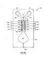
- Fig. 16 is one illustration of such use.
- the ideal liquid junction between two disparate liquids used in a differential potentiometric-test is one in which no mixing of the liquids occurs in the ion bridge.
- Fig. 16 is a view of a multiple test element 400 wherein the top cover sheet, having inlet apertures 410 occupying the positions shown when assembled, has been removed (and is otherwise not shown).
- the bottom sheet 18g similar to top sheet 18c of the embodiment of Fig. 10 and 13, has a cavity defining the capillary transport zone 30g, and liquid-delivery zones 420 and 430 which are also capillary zones.
- the ribs of zone 30g are substantilly as shown in Fig. 10, that is, do not extend the full capillary distance separating the capillary surface of the apertured top sheet, from surface 14g of sheet 18g.
- a partition 440 that does extend the full capillary distance may be disposed between zones 420 and 430 to direct flow of the two liquids downward into zone 30g, to create concurrent flow, rather than towards each other as would create opposing flows.
- apertures 450 are provided all the way through sheet 18g. These apertures are configured substan- ; tially as is described in U.S. Patent No. 4,271,119, and particularly as in Fig. 10. Although the long axis of apertures 450 is normal to slots 142g', there is enough flow perpendicular to such long axis as to insure complete wetting of the apertures to provide continued flow out of the plane of surface 14g. Located underneath sheet 18g and each of the apertures 450 is an ion-selective electrode (ISE) constructed also as described concerning Fig. 10 of the '119 patent.
- ISE ion-selective electrode
- ISE 460 and 460' are specific to one ionic analyte, 462 and 462' to a second ionic analyte, 464 and 464' to a third ionic analyte, and 466 and 466' to a fourth ionic analyte.
- the distance between apertures 450 for any one pair of ISE's is about 1 cm.
- Cavity 470 in sheet 18g is a drain cavity that collects overflow. It terminates in a vent aperture 480. Alternatively, cavity 470 can be omitted, where a reservoir is not needed.
- zone 30 g is effective to provide the desired concurrent flow of both liquids, even when the viscosity of one liquid would normally make it flow substantially slower than the other.
- the effect appears to be one in which the faster flowing liquid "pulls" the slower flowing liquid along with it.
Abstract
Description
- This invention is directed to a device and a method for transporting liquid by capillary attraction between two opposing surfaces.
- In the capillary transport of liquids between opposing surfaces, two liquids can be brought together by flowing in opposing directions, creating a flow in opposition, or they can be transported in a concurrent flow wherein they advance simultaneously and together through the same part of the zone. In the first case, the intent can be to have only one of the two liquids in any one of two parts of the zone, the liquids meeting at a junction between the two parts. In the second, concurrent flow case, the intent can be for each of the liquids to traverse essentially all of the transport zone, arriving in generally equal amounts at a final destination.
- In either case, it can be important that the liquids flow in a controlled manner. For example, if opposing flow transport is being used as an ion bridge between ion-selective electrodes, hereinafter "ISE", two liquids are introduced into the spacing between the surfaces to advance in opposite directions ideally at equal rates to meet at a predetermined junction, as explained, for example, in U.S. Patent No. 4,271,119, issued on June 2, 1981. However, when testing biological liquids against a reference liquid having a different viscosity and/or surface tension, using the differential analysis of the aforesaid patent, it is common for the one liquid to flow much faster than the other. If the faster flow pushes into contact with the ISE that is intended for the other liquid, the test is ruined. Although a coating of a water- swellable layer has been found to solve this problem, such coatings do require the additional step of applying the coating. In some cases it would be advantageous if a speed-of-flow control could be constructed that does not require an additional layer of material. On the other hand, mechanical constraints to flow tend to be objectionable because they can cause air entrapment. Such air entrapment is undesirable as it tends to unpredictably interfere with flow through the transport. A capillary transport device is described in U.S. Patent No. 4,233,029, issued on November 11, 1980, having ribs as energy barriers that restrain the flow between capillary surfaces while avoiding air entrapment. Thus, a liquid transport device is known in accordance with the prior art portion of
claim 1 hereinafter set forth. However, to make the flow completely predictable, the ribs of such known device are provided on both of the opposed capillary surfaces. It is desirable at least from the standpoint of production to provide controlled flow wherein at least one of the opposing capillary surfaces is left generally smooth. Prior to this invention, it has not been clear how this could be done and still avoid air entrapment. - Thus the problem of the invention has been to mechanically control the liquid flow in a capillary transport zone, without air entrapment, by a construction that allows the use of a generally smooth surface as one of the capillary-defining surfaces, thus simplifying production. This problem is solved with a liquid transport device having two opposed surfaces spaced apart a distance effective to induce capillary flow between the surfaces of introduced liquid and thus provide a capillary zone, and access means for admitting liquids to the zone. One of the surfaces of this device includes spaced-apart energy barriers which a) extend across a portion of the primary direction of travel of liquid through the zone, and b) have a height less than the distance between the surfaces; characterized in that at least every other one of the barriers includes slot means for preventing air entrapment between the energy barriers; and the other of the surfaces is free of such energy barriers.
- In accordance with another aspect of the invention, the solution of the problem allows the practice of a method for providing a non-mixing junction between two dissimilar but miscible liquids, the method comprising the steps of
- a) introducing both of the liquids into a transport zone having a spacing that induces the liquids to flow under capillary attraction, and
- b) directing the liquids to flow through the zone, side-by-side, along serpentine paths.
- Thus, it is an advantageous effect of the present invention that one of the capillary surfaces of the transport device provides mechanical energy barriers to the flow effective to control the velocity and the shape of the advancing contact line, without causing air entrapment.
- It is a further advantageous feature that such control is achieved without requiring both opposing capillary surfaces to be specially modified.
- It is another advantageous effect that two miscible liquids can be made to flow side-by-side without convective mixing.
- The present invention will now be described by way of example with reference to the accompanying drawings in which:-
- Fig. 1 is a fragmentary isometric view, partially broken away, of a capillary transport device constructed in accordance with the invention;
- Fig. 2 is a fragmentary sectional view taken generally along the plane of line II-II of Fig. 1 that extends through and generally parallel to the transport zone, except that a transported liquid has been added;
- Figs. 3A-3E are fragmentary views similar to that of Fig. 2, but illustrating subsequent meniscus positions compared to the previous view;
- Fig. 4 is a fragmentary view similar to that of Fig. 2, but illustrating a comparative example;
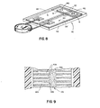
- Fig. 5 is a vertical sectional view taken generally along the plane of line V-V of Fig. 1;
- Fig. 6 is a plot of the ratio of Area Ai in the process of being filled between two ribs versus the total area AT between such two ribs against the ratio of time Ti in the process of being used to fill area Ai, versus the total time TT needed to fill area AT;
- Fig. 7 is a fragmentary view similar to that of Fig. 2, but illustrating an alternate embodiment of the invention;
- Fig. 8 is an isometric view of an ISE test element utilizing the capillary transport device of the invention as the ion bridge;
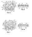
- Fig. 9 is a sectional view similar to that of Fig. 2, but illustrating yet another alternate embodiment;
- Figs. 10-11 are each a fragmentary bottom view similar to that of Fig. 2, but illustrating still other alternate embodiments that have the bottom member removed;
- Fig. 12 is a fragmentary view similar to that of Fig. 11, except that it is a sectional view taken -J-within the capillary spacing between the opposing surfaces, illustrating still another embodiment;
- Figs. 13-14 are vertical section views similar to that of Fig. 5, but taken along lines XIII-XIII and XIV-XIV, respectively, of Figs. 10 and 11;
- Fig. 15 is a fragmentary sectional view similar to that of Fig. 12, but illustrating still another embodiment; and
- Fig. 16 is a plan view of a portion of an ISE test element constructed using the principles of the previous embodiments.
- As is apparent from the following description, the device of the invention is preferably used to convey one or more biological liquids, and most preferably two such liquids to a junction interface within the device, such as in an ion bridge. Also, it preferably utilizes energy barriers that are linear and parallel to each other. In addition, the invention is applicable to capillary transport devices for any liquid, regardless of the particular end use, particularly when the speed of transport through the device or the shape of the advancing meniscus needs to be controlled. It is further applicable to such capillary transport devices whether or not the energy barriers are linear or parallel.
-
Device 10, Figs. 1-3, is illustrative of the invention. It comprises twoopposed surfaces top member 16 and abottom member 18, respectively.Surfaces edges transport zone 30. The liquid to be transported is introduced through apertures shown dotted in Fig. 5, in either member, or an aperture formed by exposing the capillary gap at either end. Althoughsurface 14 is shown as being concave away fromsurface 12, this is not critical since the two surfaces can also be parallel. - In accord with one aspect of the invention, to control the rate of flow within
zone 30 along the primary flow path (arrow 32, Fig. 2), energy barriers in the form ofribs 40 are provided on one of the surfaces, such assurface 14, extending into the flow ofpath 32. Such ribs do not, however, extend all the way across to the opposing surface, in thiscase surface 12, but instead leave a spacing "d", Fig. 5. As will be readily apparent, the maximum spacing "s", Fig. 5, betweensurfaces ribs 40 extend all the way to the edges of the zone until they intersect the risingsidewalls 41 at such edges. - To prevent air entrapment, a flow-through
slot 42 is provided in each of the ribs. (Not all such slots nor all the ribs have been numbered in Figs. 1 or 2, for purposes of clarity.) The slots have a maximum dimension x transverse to the direction offlow 32, Fig. 5, that is selected in light of the desired flow characteristics. I have discovered that if allslots 42 are omitted, flow over the ribs tends to be unpredictable to the point that air entrapment occurs due to left, right or both left and right edge fillings, as described in detail hereafter. Particularly this is a problem if spacing s, Fig. 5, is 50 um or less, since in such a case any sag intop member 16 extending lengthwise in the direction of the flow tends to create, during liquid transport, air pockets in the center. The mechanism is believed to be that the sag reduction in the spacing s in front of the meniscus encourages liquid to wrap around air to form pockets. Such sag could occur, for example, due to deformation during storage, and the like. -
Slots 42 are located betweenedges position 50 shown in Fig. 2, because of the energy barrier created by rib 40'. Thereafter, the meniscus surges forward as atongue 52, Figs. 3A-3C, in the direction indicated byarrow 54, Fig. 3B, the vicinity of theslot 42, until, Figs. 3C and 3D,tongue 52 strikes the nextadjacent rib 40" in the vicinity ofslot 42. At this point in time the liquid moves rapidly laterally in both directions from thetongue 52, to fill in the gap betweenribs 40' and 40". As a result, air is pushed out in front of the meniscus, from the center outward, until, Fig. 3E, the gap is essentially filled. The process then repeats itself. It is this constant filling from the approximate center, outwards, that avoids air entrapment. - In contrast, Fig. 4, if no slot occurs in two
adjacent ribs edges arrows arrow 54. When the liquid reachesrib 410, it tends to move or fill laterally towards the center,arrows 450. It is this lateral movement from the left or right edge towards, rather than away from, the center that tends to cause air entrapment. - Most preferably, each of the
slots 42 is aligned with the next adjacent slots of the next adjacent ribs. In another preferred embodiment, the slots are only approximately aligned, a portion of each slot lining up with a portion of the slot of the next adjacent rib. - The shape of
slots 42 is not critical. Thus, V-shapes, irregular shapes, semi-circles and the like are also useful. - In the
event device 10 is to be used, as is preferred, to transport two different liquids from different locations into contact with each other, the air between the two advancing wavefronts has to be released. Preferably this is accomplished, Fig. 5, by a series of air release apertures 60 and 62 formed inmember 16 nearedges - A variety of values are possible for dimensions "d" and "x", Fig. 5. Preferably, d is between about 0.007 cm and about 0.02 cm, and x is between about 0.02 cm and about 0.2 cm. Most preferably, x is between about 7% and about 36% of the total width w of
zone 30. - In addition,
ribs 40 can have a variety of spacings y, Fig. 2. Most preferably, the y spacing is between about 0.05 cm and about 0.07 cm. - A variety of materials is useful in making
device 10, although such materials should be selected for wettability with the liquid being transported. More specifically, the materials are preferably selected to give a contact angle that is between about 65° and about 82° for the liquid being transported. - Fig. 6 demonstrates the flow characteristics of
zone 30 when using dyed water, polystyrene asmember 18, and poly(ethylene terephthalate) asmember 16. The initiation oftongue 52 is quite slow until Ti/TT - about 0.4 is reached, at which point area fill occurs more rapidly. As noted above, Ti/TT is the ratio of the time taken to fill fractional area Ai, to the time TT required to fill the total area AT between two ribs. Ifsurface 12 were more hydrophobic, the point of initiation would be significantly delayed, but the slope of the curve would be only slightly altered. - Not every rib need be slotted, if every other rib is, as shown in the embodiment of Fig. 7. Parts similar to those previously described bear the same reference numeral, to which the distinguishing suffix "a" has been added. (The dots representing the liquid have been omitted for clarity.) Thus, device 10a comprises a
zone 30a constructed as before, except thatslots 42a occur only in everyother rib 40a. In between each slotted rib is one and only oneunslotted rib 100. The flow proceeds thusly: When the liquid goes from first-encounteredrib 40a in the direction ofarrow 110 to the meniscus position shown in dotted line onrib 100, the mechanism is as described for the embodiment of Fig. 3. However, flow then proceeds as perarrows 120 as per the mechanism of comparative example Fig. 4, to provide the meniscus shape shown as a solid curve. Nevertheless, the risk of liquid closure in the center so as to entrap air is minimized by the presence ofslot 42a in second-encounteredrib 40a. The flow from thelatter rib 40a will then repeat that shown for the first-encounteredrib 40a. Thus, slots in every other rib act to re-initiate flow at a central location (between edges 20a and 22a) into the space between the rib energy barriers. - Fig. 8 illustrates one use of such a capillary transport device. Specifically, as in U.S. Patent No. 4,302,313, the device functions as an ion bridge 136 covering and contacting two ion-
selective electrodes 114 and l14'constructed and mounted in asupport element 112 as described in the '313 patent.Apertures member 16 are access apertures providing passage of two different liquids to the capillary transport zone, and two additional apertures not shown, inmember 18 underapertures - Equivalent energy barriers, shown in Fig. 9, are useful in lieu of the above-described ribs. For example, alternating portions of
surface 14b can be permanently converted from a hydrophobic nature, which is common in plastics, to a hydrophilic nature by using one or more of the techniques, such as corona discharge, described in col. 9 of the aforesaid U.S. Patent No. 4,233,029. The result is to render hydrophilic, and thus more easily wettable by the liquid, the portions, marked with squiggly lines, ofsurface 14b that were unoccupied by ribs in the previously described embodiments. Theportions 40b that remain hydrophobic, act as energy barriers.Portions 42b extending betweenportions 40b function as slots between these energy barriers. - The preceding embodiments work best if flow of the two liquids is in opposite directions. If concurrent flow is desired, the embodiments of Figs. 10-15 are preferred. Parts similar to those previously described bear the same reference numeral to which the distinguishing suffix "c", "d", "e" or "f" is appended.
- Thus, in Figs. 10 and 13, a
capillary transport zone 30c ofdevice 10c is formed between two opposingsurfaces ribs 40c extend fromsurface 14c as in the previous embodiment. However, surfaces 12c and 14c preferably are reversed in their positions--that is,surface 14c becomes the upper surface so thatribs 40c depend downwardly during use, Fig. 13. In addition, slots are provided withinribs 40c so that about one-half of the ribs (labeled 40c', Fig. 10) have one slot, 42c, whereas the other half (labeled 40c", Figs. 10 and 13) have twoslots 142c' and 142c". Furthermore, the slots of two adjacent ribs are transversely displaced, relative to the primary direction of flow 32c, from each other, so thatslots 42c are offset from or misaligned withslots 142c' and 142c". - The concurrent flow of the two liquids in
device 10c proceeds as shown by arrows 200,202 and 210, 212. That is, if the two liquids are introduced from two different sources at the twoslots 142c' and 142c", respectively, they will tend to form menisci M and M', Fig. 10. These menisci will then meet and 5 flow out through thenext slot 42c as shown bysolid arrows zone 30c and as long as they are simultaneously introduced into thetransport zone 30c. (Diffusion mixing is presumed to occur.) As shown by differential dye concentration studies, the advancing liquids stay split up as shown byarrows slots 142c' and 142c". Thereafter, the meniscus shapes will be similar to that of M and M', but advanced farther into the device. Alternating flow throughslots 42c andslots 142c', 142c" serves thus to advance the two liquids as two separate streams flowing side-by-side in the direction of arrow 32c. - In the embodiment of Figs. 11 and 14, the primary difference from the previously-described embodiment is that the
middle portion 300 ofribs 40d" ; extends completely across zone 30d as a wall to connectsurfaces 12d and 14d. The remainingportions 302 of such ribs, as well asribs 40d', are the same as before. Also, as before,slots 142d' and 142d" ofribs 40d" are transversely displaced, rather than aligned, withslots 42d ofribs 40d'. Thus, the flow pattern is similar in that the liquid advances via the paths ofarrows 200d, 202d, and then paths ofarrows 210d, 212d. (Alternatively,portions 302 ofribs 40d" can be omitted entirely, leaving justwalls 300.) - In the embodiment of Fig. 12, all the energy barriers across the primary flow direction have more than one slot. The barriers are of two types--
ribs 40e, and wall means 300e connecting opposing capillary surfaces. The ribs and the wall means alternate with each other, andrib slots 42e are transversely displaced, and thus misaligned, withslots 142e of wall means 300e. The flow pattern is very similar to that of Fig. 11. - Alternatively, instead of the rectilinear configuration of
energy barriers - In all of the aforesaid embodiments, it is not essential that the ribs that have rib slots, be square with respect to the sidewalls. Thus, in the embodiment of Fig. 15, the construction is similar to that of Fig. 11, except that
ribs 40f' are joined tosidewalls 41f with a curved intersection. (Ribs 300f extend the full height of the capillary zone.) The curved intersection by whichribs 40f' join the sidewalls acts to induce a more sweeping action by the liquid and thus to minimize stagnant action by the liquid. Useful radii of curvature for such curved intersections include those wherein the ratio of the radius of curvature, R, to the total width w ofzone 30f, is about 35/1000. - In addition to the uses already described, the embodiments of Figs. 10-15 can also be used to handle a flow of a single liquid, particularly highly viscous liquids. For example, pathological liquids will flow by a decrease in flow restrictions provided by the serpentine paths described, while maintaining control over flow times.
- The embodiments of Figs. 10-15 can be used wherever concurrent flow, but without mixing, is desired. Fig. 16 is one illustration of such use. As has been indicated in prior literature, the ideal liquid junction between two disparate liquids used in a differential potentiometric-test is one in which no mixing of the liquids occurs in the ion bridge. Thus, ; Fig. 16 is a view of a
multiple test element 400 wherein the top cover sheet, havinginlet apertures 410 occupying the positions shown when assembled, has been removed (and is otherwise not shown). The bottom sheet 18g, similar totop sheet 18c of the embodiment of Fig. 10 and 13, has a cavity defining thecapillary transport zone 30g, and liquid-delivery zones zone 30g are substantilly as shown in Fig. 10, that is, do not extend the full capillary distance separating the capillary surface of the apertured top sheet, from surface 14g of sheet 18g. However, optionally apartition 440 that does extend the full capillary distance may be disposed betweenzones zone 30g, to create concurrent flow, rather than towards each other as would create opposing flows. - In the
slots 142g' between everyother rib 40g",apertures 450 are provided all the way through sheet 18g. These apertures are configured substan- ; tially as is described in U.S. Patent No. 4,271,119, and particularly as in Fig. 10. Although the long axis ofapertures 450 is normal toslots 142g', there is enough flow perpendicular to such long axis as to insure complete wetting of the apertures to provide continued flow out of the plane of surface 14g. Located underneath sheet 18g and each of theapertures 450 is an ion-selective electrode (ISE) constructed also as described concerning Fig. 10 of the '119 patent. The ISE's are paired as follows:ISE 460 and 460' are specific to one ionic analyte, 462 and 462' to a second ionic analyte, 464 and 464' to a third ionic analyte, and 466 and 466' to a fourth ionic analyte. Most preferably, the distance betweenapertures 450 for any one pair of ISE's is about 1 cm. -
Cavity 470 in sheet 18g is a drain cavity that collects overflow. It terminates in avent aperture 480. Alternatively,cavity 470 can be omitted, where a reservoir is not needed. - As a result, two dissimilar but miscible liquids introduced into
zone 30g viaapertures 410 will flow side-by-side, along serpentine paths, producing a junction that approximately bisectsapertures 42c and is substantially free of convection mixing. Portions of each liquid, one of which is a reference liquid, are withdrawn throughapertures 450' into contact with their respective ISE's, and the differential potentiometric method of measuring is accomplished in the usual manner with an electrometer, not shown. - It has been found that
zone 30 g is effective to provide the desired concurrent flow of both liquids, even when the viscosity of one liquid would normally make it flow substantially slower than the other. The effect appears to be one in which the faster flowing liquid "pulls" the slower flowing liquid along with it.
Claims (10)
and said slot means includes means for initiating liquid flow into the space between said energy barriers at a predetermined location between said edges.
Applications Claiming Priority (4)
| Application Number | Priority Date | Filing Date | Title |
|---|---|---|---|
| US57905684A | 1984-02-10 | 1984-02-10 | |
| US579056 | 1984-02-10 | ||
| US06/666,719 US4618476A (en) | 1984-02-10 | 1984-10-31 | Capillary transport device having speed and meniscus control means |
| US666719 | 1984-10-31 |
Publications (3)
| Publication Number | Publication Date |
|---|---|
| EP0153110A2 true EP0153110A2 (en) | 1985-08-28 |
| EP0153110A3 EP0153110A3 (en) | 1987-05-13 |
| EP0153110B1 EP0153110B1 (en) | 1990-10-31 |
Family
ID=27077648
Family Applications (1)
| Application Number | Title | Priority Date | Filing Date |
|---|---|---|---|
| EP85300862A Expired EP0153110B1 (en) | 1984-02-10 | 1985-02-08 | Capillary transport device having speed and meniscus control means, and method of using |
Country Status (5)
| Country | Link |
|---|---|
| US (1) | US4618476A (en) |
| EP (1) | EP0153110B1 (en) |
| JP (1) | JPH0616829B2 (en) |
| CA (1) | CA1224248A (en) |
| DE (1) | DE3580289D1 (en) |
Cited By (10)
| Publication number | Priority date | Publication date | Assignee | Title |
|---|---|---|---|---|
| EP0215419A2 (en) * | 1985-09-18 | 1987-03-25 | Miles Inc. | Volume metering capillary gap device for applying a liquid sample onto a reactive surface |
| EP0508530A1 (en) * | 1991-04-10 | 1992-10-14 | Eastman Kodak Company | Gravity assisted collection device |
| US5225163A (en) * | 1989-08-18 | 1993-07-06 | Angenics, Inc. | Reaction apparatus employing gravitational flow |
| EP0579997A1 (en) * | 1992-07-17 | 1994-01-26 | E.I. Du Pont De Nemours And Company | Disposable cartridge for ion selective electrode sensors |
| WO2009061414A1 (en) * | 2007-11-08 | 2009-05-14 | Corning Incorporated | Dual inlet microchannel device and method for using same |
| EP2240600A1 (en) * | 2007-08-29 | 2010-10-20 | Plexera Bioscience Llc | Microfluidic apparatus for wide area microarrays |
| US7824624B2 (en) | 2006-04-07 | 2010-11-02 | Corning Incorporated | Closed flow-through microplate and methods for using and manufacturing same |
| WO2013004673A1 (en) * | 2011-07-05 | 2013-01-10 | Boehringer Ingelheim Microparts Gmbh | Microfluidic structure having recesses |
| KR20170073695A (en) * | 2014-11-28 | 2017-06-28 | 도요세이칸 그룹 홀딩스 가부시키가이샤 | Micro liquid transfer structure and analysis device |
| WO2018050750A1 (en) * | 2016-09-15 | 2018-03-22 | Softhale Nv | Valve, in particular for a device for administering a liquid medicament, and a corresponding device for administering a liquid medicament |
Families Citing this family (90)
| Publication number | Priority date | Publication date | Assignee | Title |
|---|---|---|---|---|
| US5223219A (en) * | 1992-04-10 | 1993-06-29 | Biotrack, Inc. | Analytical cartridge and system for detecting analytes in liquid samples |
| US5222808A (en) * | 1992-04-10 | 1993-06-29 | Biotrack, Inc. | Capillary mixing device |
| US5587128A (en) * | 1992-05-01 | 1996-12-24 | The Trustees Of The University Of Pennsylvania | Mesoscale polynucleotide amplification devices |
| US5304487A (en) * | 1992-05-01 | 1994-04-19 | Trustees Of The University Of Pennsylvania | Fluid handling in mesoscale analytical devices |
| US5637469A (en) | 1992-05-01 | 1997-06-10 | Trustees Of The University Of Pennsylvania | Methods and apparatus for the detection of an analyte utilizing mesoscale flow systems |
| US5498392A (en) * | 1992-05-01 | 1996-03-12 | Trustees Of The University Of Pennsylvania | Mesoscale polynucleotide amplification device and method |
| US5726026A (en) * | 1992-05-01 | 1998-03-10 | Trustees Of The University Of Pennsylvania | Mesoscale sample preparation device and systems for determination and processing of analytes |
| US6953676B1 (en) * | 1992-05-01 | 2005-10-11 | Trustees Of The University Of Pennsylvania | Mesoscale polynucleotide amplification device and method |
| US5486335A (en) * | 1992-05-01 | 1996-01-23 | Trustees Of The University Of Pennsylvania | Analysis based on flow restriction |
| US5296375A (en) * | 1992-05-01 | 1994-03-22 | Trustees Of The University Of Pennsylvania | Mesoscale sperm handling devices |
| US5660798A (en) * | 1993-04-20 | 1997-08-26 | Actimed Laboratories, Inc. | Apparatus for red blood cell separation |
| US5766552A (en) * | 1993-04-20 | 1998-06-16 | Actimed Laboratories, Inc. | Apparatus for red blood cell separation |
| US5427663A (en) * | 1993-06-08 | 1995-06-27 | British Technology Group Usa Inc. | Microlithographic array for macromolecule and cell fractionation |
| US5447689A (en) * | 1994-03-01 | 1995-09-05 | Actimed Laboratories, Inc. | Method and apparatus for flow control |
| EP0929658A4 (en) | 1996-08-26 | 2005-11-02 | Univ Princeton | Reversibly sealable microstructure sorting devices |
| US6591852B1 (en) | 1998-10-13 | 2003-07-15 | Biomicro Systems, Inc. | Fluid circuit components based upon passive fluid dynamics |
| US6637463B1 (en) | 1998-10-13 | 2003-10-28 | Biomicro Systems, Inc. | Multi-channel microfluidic system design with balanced fluid flow distribution |
| US6601613B2 (en) | 1998-10-13 | 2003-08-05 | Biomicro Systems, Inc. | Fluid circuit components based upon passive fluid dynamics |
| KR20010089295A (en) | 1998-10-13 | 2001-09-29 | 마이클 알. 맥닐리 | Fluid circuit components based upon passive fluid dynamics |
| US6319719B1 (en) | 1999-10-28 | 2001-11-20 | Roche Diagnostics Corporation | Capillary hematocrit separation structure and method |
| US6451264B1 (en) * | 2000-01-28 | 2002-09-17 | Roche Diagnostics Corporation | Fluid flow control in curved capillary channels |
| US6406672B1 (en) | 2000-01-28 | 2002-06-18 | Roche Diagnostics | Plasma retention structure providing internal flow |
| US6867049B1 (en) * | 2000-09-27 | 2005-03-15 | Becton, Dickinson And Company | Method for obtaining increased particle concentration for optical examination |
| US6555387B1 (en) * | 2000-09-27 | 2003-04-29 | Becton, Dickinson And Company | Method for producing thin liquid samples for microscopic analysis |
| US6599480B1 (en) * | 2000-09-27 | 2003-07-29 | Becton, Dickinson And Company | Apparatus for obtaining increased particle concentration for optical examination |
| DE10123259A1 (en) * | 2001-05-12 | 2002-11-21 | Eppendorf Ag | Microfluidic storage and / or dosing component |
| US6755949B1 (en) | 2001-10-09 | 2004-06-29 | Roche Diagnostics Corporation | Biosensor |
| US7459127B2 (en) | 2002-02-26 | 2008-12-02 | Siemens Healthcare Diagnostics Inc. | Method and apparatus for precise transfer and manipulation of fluids by centrifugal and/or capillary forces |
| JP2006507921A (en) | 2002-06-28 | 2006-03-09 | プレジデント・アンド・フェロウズ・オブ・ハーバード・カレッジ | Method and apparatus for fluid dispersion |
| US7125711B2 (en) | 2002-12-19 | 2006-10-24 | Bayer Healthcare Llc | Method and apparatus for splitting of specimens into multiple channels of a microfluidic device |
| US7094354B2 (en) | 2002-12-19 | 2006-08-22 | Bayer Healthcare Llc | Method and apparatus for separation of particles in a microfluidic device |
| GB0307428D0 (en) | 2003-03-31 | 2003-05-07 | Medical Res Council | Compartmentalised combinatorial chemistry |
| GB0307403D0 (en) | 2003-03-31 | 2003-05-07 | Medical Res Council | Selection by compartmentalised screening |
| US20060078893A1 (en) | 2004-10-12 | 2006-04-13 | Medical Research Council | Compartmentalised combinatorial chemistry by microfluidic control |
| EP2266687A3 (en) | 2003-04-10 | 2011-06-29 | The President and Fellows of Harvard College | Formation and control of fluidic species |
| US7435381B2 (en) * | 2003-05-29 | 2008-10-14 | Siemens Healthcare Diagnostics Inc. | Packaging of microfluidic devices |
| DE10325110B3 (en) * | 2003-05-30 | 2005-01-13 | Universität Freiburg | Fluid channel, for use e.g. in biotechnology, is filled with liquid using capillary action, and comprises two sections separated by barrier preventing migration of liquid between sections, except at closed end |
| US20040265172A1 (en) * | 2003-06-27 | 2004-12-30 | Pugia Michael J. | Method and apparatus for entry and storage of specimens into a microfluidic device |
| US20040265171A1 (en) * | 2003-06-27 | 2004-12-30 | Pugia Michael J. | Method for uniform application of fluid into a reactive reagent area |
| US7347617B2 (en) | 2003-08-19 | 2008-03-25 | Siemens Healthcare Diagnostics Inc. | Mixing in microfluidic devices |
| CN104069784B (en) | 2003-08-27 | 2017-01-11 | 哈佛大学 | electronic control of fluidic species |
| DE10354806A1 (en) * | 2003-11-21 | 2005-06-02 | Boehringer Ingelheim Microparts Gmbh | sample carrier |
| DE10360220A1 (en) * | 2003-12-20 | 2005-07-21 | Steag Microparts Gmbh | Fine structure arrangement in fluid ejection system, has predetermined region in transitional zone between inlet and discharge ports, at which capillary force is maximum |
| US20050221339A1 (en) | 2004-03-31 | 2005-10-06 | Medical Research Council Harvard University | Compartmentalised screening by microfluidic control |
| US9477233B2 (en) | 2004-07-02 | 2016-10-25 | The University Of Chicago | Microfluidic system with a plurality of sequential T-junctions for performing reactions in microdroplets |
| US7968287B2 (en) | 2004-10-08 | 2011-06-28 | Medical Research Council Harvard University | In vitro evolution in microfluidic systems |
| WO2006061026A2 (en) * | 2004-12-09 | 2006-06-15 | Inverness Medical Switzerland Gmbh | A micro fluidic device and methods for producing a micro fluidic device |
| EP1843849A2 (en) * | 2005-01-12 | 2007-10-17 | Inverness Medical Switzerland GmbH | A method of producing a microfluidic device and microfluidic devices |
| ATE503578T1 (en) * | 2005-01-27 | 2011-04-15 | Boehringer Ingelheim Micropart | USE OF A DEVICE FOR EXAMINING SAMPLE FLUID |
| JP4693657B2 (en) * | 2005-03-29 | 2011-06-01 | シチズンホールディングス株式会社 | Biosensor |
| EP1904232A2 (en) * | 2005-07-07 | 2008-04-02 | Inverness Medical Switzerland GmbH | A method of performing a test, a support instrument and a microliquid system comprising such support instrument |
| US8921102B2 (en) | 2005-07-29 | 2014-12-30 | Gpb Scientific, Llc | Devices and methods for enrichment and alteration of circulating tumor cells and other particles |
| WO2007054850A2 (en) * | 2005-11-09 | 2007-05-18 | Koninklijke Philips Electronics N.V. | Device for testing a fluid |
| CA2636855C (en) | 2006-01-11 | 2016-09-27 | Raindance Technologies, Inc. | Microfluidic devices and methods of use in the formation and control of nanoreactors |
| JP4713397B2 (en) * | 2006-01-18 | 2011-06-29 | 株式会社リコー | Microchannel structure and microdroplet generation system |
| AU2007210152A1 (en) * | 2006-01-27 | 2007-08-09 | President And Fellows Of Harvard College | Fluidic droplet coalescence |
| EP2047910B1 (en) | 2006-05-11 | 2012-01-11 | Raindance Technologies, Inc. | Microfluidic device and method |
| US9562837B2 (en) | 2006-05-11 | 2017-02-07 | Raindance Technologies, Inc. | Systems for handling microfludic droplets |
| DE102006024355B4 (en) * | 2006-05-19 | 2008-04-03 | Fraunhofer-Gesellschaft zur Förderung der angewandten Forschung e.V. | Microfluidic arrangement for the detection of chemical, biochemical molecules and / or particles contained in samples |
| US20070280856A1 (en) * | 2006-06-02 | 2007-12-06 | Applera Corporation | Devices and Methods for Controlling Bubble Formation in Microfluidic Devices |
| US20070280857A1 (en) * | 2006-06-02 | 2007-12-06 | Applera Corporation | Devices and Methods for Positioning Dried Reagent In Microfluidic Devices |
| EP2077912B1 (en) | 2006-08-07 | 2019-03-27 | The President and Fellows of Harvard College | Fluorocarbon emulsion stabilizing surfactants |
| EP2101917A1 (en) * | 2007-01-10 | 2009-09-23 | Scandinavian Micro Biodevices A/S | A microfluidic device and a microfluidic system and a method of performing a test |
| US8772046B2 (en) | 2007-02-06 | 2014-07-08 | Brandeis University | Manipulation of fluids and reactions in microfluidic systems |
| WO2008130623A1 (en) | 2007-04-19 | 2008-10-30 | Brandeis University | Manipulation of fluids, fluid components and reactions in microfluidic systems |
| CN101980769B (en) * | 2008-03-28 | 2013-06-12 | 爱科来株式会社 | Fluid agitation method, fluid agitation system, and cartridge |
| WO2010009365A1 (en) | 2008-07-18 | 2010-01-21 | Raindance Technologies, Inc. | Droplet libraries |
| EP2213364A1 (en) * | 2009-01-30 | 2010-08-04 | Albert-Ludwigs-Universität Freiburg | Phase guide patterns for liquid manipulation |
| WO2010111231A1 (en) | 2009-03-23 | 2010-09-30 | Raindance Technologies, Inc. | Manipulation of microfluidic droplets |
| WO2011042564A1 (en) | 2009-10-09 | 2011-04-14 | Universite De Strasbourg | Labelled silica-based nanomaterial with enhanced properties and uses thereof |
| EP2517025B1 (en) | 2009-12-23 | 2019-11-27 | Bio-Rad Laboratories, Inc. | Methods for reducing the exchange of molecules between droplets |
| US9399797B2 (en) | 2010-02-12 | 2016-07-26 | Raindance Technologies, Inc. | Digital analyte analysis |
| EP2534267B1 (en) | 2010-02-12 | 2018-04-11 | Raindance Technologies, Inc. | Digital analyte analysis |
| US9366632B2 (en) | 2010-02-12 | 2016-06-14 | Raindance Technologies, Inc. | Digital analyte analysis |
| US10351905B2 (en) | 2010-02-12 | 2019-07-16 | Bio-Rad Laboratories, Inc. | Digital analyte analysis |
| WO2012045012A2 (en) | 2010-09-30 | 2012-04-05 | Raindance Technologies, Inc. | Sandwich assays in droplets |
| EP2673614B1 (en) | 2011-02-11 | 2018-08-01 | Raindance Technologies, Inc. | Method for forming mixed droplets |
| EP2675819B1 (en) | 2011-02-18 | 2020-04-08 | Bio-Rad Laboratories, Inc. | Compositions and methods for molecular labeling |
| DE202012013668U1 (en) | 2011-06-02 | 2019-04-18 | Raindance Technologies, Inc. | enzyme quantification |
| US8841071B2 (en) | 2011-06-02 | 2014-09-23 | Raindance Technologies, Inc. | Sample multiplexing |
| US8658430B2 (en) | 2011-07-20 | 2014-02-25 | Raindance Technologies, Inc. | Manipulating droplet size |
| US11901041B2 (en) | 2013-10-04 | 2024-02-13 | Bio-Rad Laboratories, Inc. | Digital analysis of nucleic acid modification |
| US9944977B2 (en) | 2013-12-12 | 2018-04-17 | Raindance Technologies, Inc. | Distinguishing rare variations in a nucleic acid sequence from a sample |
| WO2015103367A1 (en) | 2013-12-31 | 2015-07-09 | Raindance Technologies, Inc. | System and method for detection of rna species |
| US10647981B1 (en) | 2015-09-08 | 2020-05-12 | Bio-Rad Laboratories, Inc. | Nucleic acid library generation methods and compositions |
| AU2017212754B2 (en) | 2016-01-29 | 2023-06-29 | Purigen Biosystems, Inc. | Isotachophoresis for purification of nucleic acids |
| JP7387430B2 (en) * | 2016-06-27 | 2023-11-28 | ゾエティス サービシズ リミテッド ライアビリティ カンパニー | Devices with modified conduits |
| JP7170047B2 (en) * | 2017-12-21 | 2022-11-11 | ラジオメーター・メディカル・アー・ペー・エス | Device for containing a fluid sample |
| US10898895B2 (en) | 2018-09-13 | 2021-01-26 | Talis Biomedical Corporation | Vented converging capillary biological sample port and reservoir |
| US10820847B1 (en) | 2019-08-15 | 2020-11-03 | Talis Biomedical Corporation | Diagnostic system |
Citations (3)
| Publication number | Priority date | Publication date | Assignee | Title |
|---|---|---|---|---|
| US4233029A (en) * | 1978-10-25 | 1980-11-11 | Eastman Kodak Company | Liquid transport device and method |
| EP0023156A1 (en) * | 1979-07-23 | 1981-01-28 | EASTMAN KODAK COMPANY (a New Jersey corporation) | Liquid transport device for controlled liquid flow, and liquid testing device and device for determining activity of an ionic analyte including a liquid transport device |
| US4302313A (en) * | 1979-07-23 | 1981-11-24 | Eastman Kodak Company | Electrode-containing device with capillary transport between electrodes |
Family Cites Families (3)
| Publication number | Priority date | Publication date | Assignee | Title |
|---|---|---|---|---|
| US4310399A (en) * | 1979-07-23 | 1982-01-12 | Eastman Kodak Company | Liquid transport device containing means for delaying capillary flow |
| US4271119A (en) * | 1979-07-23 | 1981-06-02 | Eastman Kodak Company | Capillary transport device having connected transport zones |
| GB2090659A (en) * | 1981-01-02 | 1982-07-14 | Instrumentation Labor Inc | Analytical device |
-
1984
- 1984-10-31 US US06/666,719 patent/US4618476A/en not_active Expired - Lifetime
- 1984-11-27 CA CA000468653A patent/CA1224248A/en not_active Expired
-
1985
- 1985-02-08 EP EP85300862A patent/EP0153110B1/en not_active Expired
- 1985-02-08 DE DE8585300862T patent/DE3580289D1/en not_active Expired - Lifetime
- 1985-02-12 JP JP60025096A patent/JPH0616829B2/en not_active Expired - Fee Related
Patent Citations (3)
| Publication number | Priority date | Publication date | Assignee | Title |
|---|---|---|---|---|
| US4233029A (en) * | 1978-10-25 | 1980-11-11 | Eastman Kodak Company | Liquid transport device and method |
| EP0023156A1 (en) * | 1979-07-23 | 1981-01-28 | EASTMAN KODAK COMPANY (a New Jersey corporation) | Liquid transport device for controlled liquid flow, and liquid testing device and device for determining activity of an ionic analyte including a liquid transport device |
| US4302313A (en) * | 1979-07-23 | 1981-11-24 | Eastman Kodak Company | Electrode-containing device with capillary transport between electrodes |
Cited By (24)
| Publication number | Priority date | Publication date | Assignee | Title |
|---|---|---|---|---|
| EP0215419A3 (en) * | 1985-09-18 | 1989-04-19 | Miles Inc. | Volume metering capillary gap device for applying a liquid sample onto a reactive surface |
| EP0215419A2 (en) * | 1985-09-18 | 1987-03-25 | Miles Inc. | Volume metering capillary gap device for applying a liquid sample onto a reactive surface |
| US5225163A (en) * | 1989-08-18 | 1993-07-06 | Angenics, Inc. | Reaction apparatus employing gravitational flow |
| EP0508530A1 (en) * | 1991-04-10 | 1992-10-14 | Eastman Kodak Company | Gravity assisted collection device |
| EP0579997A1 (en) * | 1992-07-17 | 1994-01-26 | E.I. Du Pont De Nemours And Company | Disposable cartridge for ion selective electrode sensors |
| US7824624B2 (en) | 2006-04-07 | 2010-11-02 | Corning Incorporated | Closed flow-through microplate and methods for using and manufacturing same |
| US8512649B2 (en) | 2006-04-07 | 2013-08-20 | Corning Incorporated | Dual inlet microchannel device and method for using same |
| US8257665B2 (en) | 2007-04-05 | 2012-09-04 | Corning Incorporated | Dual inlet microchannel device and method for using same |
| US8974748B2 (en) | 2007-04-05 | 2015-03-10 | Corning Incorporated | Dual inlet microchannel device and method for using same |
| US20110151585A1 (en) * | 2007-04-05 | 2011-06-23 | Richard Bergman | Dual inlet microchannel device and method for using same |
| EP2240600A1 (en) * | 2007-08-29 | 2010-10-20 | Plexera Bioscience Llc | Microfluidic apparatus for wide area microarrays |
| EP2240600A4 (en) * | 2007-08-29 | 2011-08-03 | Plexera Bioscience Llc | Microfluidic apparatus for wide area microarrays |
| WO2009061414A1 (en) * | 2007-11-08 | 2009-05-14 | Corning Incorporated | Dual inlet microchannel device and method for using same |
| US9409171B2 (en) | 2011-07-05 | 2016-08-09 | Boehringer Ingelheim Microparts Gmbh | Microfluidic structure having recesses |
| WO2013004673A1 (en) * | 2011-07-05 | 2013-01-10 | Boehringer Ingelheim Microparts Gmbh | Microfluidic structure having recesses |
| TWI670114B (en) * | 2014-11-28 | 2019-09-01 | 日商東洋製罐集團控股股份有限公司 | Micro infusion structure and analysis device |
| KR20170073695A (en) * | 2014-11-28 | 2017-06-28 | 도요세이칸 그룹 홀딩스 가부시키가이샤 | Micro liquid transfer structure and analysis device |
| CN107003329A (en) * | 2014-11-28 | 2017-08-01 | 东洋制罐集团控股株式会社 | Fine liquor charging structure and analytical equipment |
| EP3226003A4 (en) * | 2014-11-28 | 2018-06-20 | Toyo Seikan Group Holdings, Ltd. | Micro liquid transfer structure and analysis device |
| WO2018050750A1 (en) * | 2016-09-15 | 2018-03-22 | Softhale Nv | Valve, in particular for a device for administering a liquid medicament, and a corresponding device for administering a liquid medicament |
| US11224734B2 (en) | 2016-09-15 | 2022-01-18 | Softhale Nv | Valve, in particular for a device for administering a liquid medicament, and a corresponding device for administering a liquid medicament |
| EP3512587B1 (en) | 2016-09-15 | 2022-02-09 | Softhale NV | Device for administering a liquid medicament |
| EP4035719A1 (en) * | 2016-09-15 | 2022-08-03 | Softhale NV | Valve, in particular for a device for administering a liquid medicament, and a corresponding device for administering a liquid medicament |
| US11819655B2 (en) | 2016-09-15 | 2023-11-21 | Softhale Nv | Valve, in particular for a device for administering a liquid medicament, and a corresponding device for administering a liquid medicament |
Also Published As
| Publication number | Publication date |
|---|---|
| US4618476A (en) | 1986-10-21 |
| EP0153110A3 (en) | 1987-05-13 |
| JPS60201254A (en) | 1985-10-11 |
| CA1224248A (en) | 1987-07-14 |
| DE3580289D1 (en) | 1990-12-06 |
| JPH0616829B2 (en) | 1994-03-09 |
| EP0153110B1 (en) | 1990-10-31 |
Similar Documents
| Publication | Publication Date | Title |
|---|---|---|
| EP0153110B1 (en) | Capillary transport device having speed and meniscus control means, and method of using | |
| CA1119831A (en) | Liquid transport device and method | |
| US10974247B2 (en) | Nanoliter array loading | |
| US6447661B1 (en) | External material accession systems and methods | |
| US8053249B2 (en) | Method of pumping fluid through a microfluidic device | |
| ES2305856T3 (en) | MIXING IN MICROFLUID DEVICES. | |
| Vulto et al. | Phaseguides: a paradigm shift in microfluidic priming and emptying | |
| EP2391444B1 (en) | Phaseguide patterns for liquid manipulation | |
| US20140141438A1 (en) | Devices And Method For Positioning Dried Reagent In Microfluidic Devices | |
| EP0988530B1 (en) | Microfabricated structures for facilitating fluid introduction into microfluidic devices | |
| ES2803402T3 (en) | Microfluidic circuit | |
| US11344877B2 (en) | Capillary pressure barriers | |
| US20070280856A1 (en) | Devices and Methods for Controlling Bubble Formation in Microfluidic Devices | |
| US7229538B2 (en) | Microfluidic device with network micro channels | |
| CN101641157B (en) | Capillary | |
| EP3749452B1 (en) | Microfluidic probe head with barrier projections | |
| JPH0278246A (en) | Basket for thin film treatment | |
| DE69630862T2 (en) | Test card for analyzers | |
| US5800691A (en) | Electrophoresis gels containing sample wells with enlarged loading area | |
| EP1075326B1 (en) | Device for transporting liquids along predetermined guideways | |
| US20040047767A1 (en) | Microfluidic channel for band broadening compensation | |
| FI69899C (en) | A building component | |
| US20210039083A1 (en) | Structures to define flow confinement shape and confinement stability with uniform aspiration | |
| NICKENS | The velocity and shape of gas slugs rising in vertical tubes and rectangular slots(Ph. D. Thesis) | |
| KR20170062645A (en) | Microfluidics chip |
Legal Events
| Date | Code | Title | Description |
|---|---|---|---|
| PUAI | Public reference made under article 153(3) epc to a published international application that has entered the european phase |
Free format text: ORIGINAL CODE: 0009012 |
|
| AK | Designated contracting states |
Designated state(s): CH DE FR GB IT LI SE |
|
| PUAL | Search report despatched |
Free format text: ORIGINAL CODE: 0009013 |
|
| AK | Designated contracting states |
Kind code of ref document: A3 Designated state(s): CH DE FR GB IT LI SE |
|
| 17P | Request for examination filed |
Effective date: 19871104 |
|
| 17Q | First examination report despatched |
Effective date: 19880202 |
|
| GRAA | (expected) grant |
Free format text: ORIGINAL CODE: 0009210 |
|
| ITF | It: translation for a ep patent filed |
Owner name: BARZANO' E ZANARDO MILANO S.P.A. |
|
| AK | Designated contracting states |
Kind code of ref document: B1 Designated state(s): CH DE FR GB IT LI SE |
|
| REF | Corresponds to: |
Ref document number: 3580289 Country of ref document: DE Date of ref document: 19901206 |
|
| ET | Fr: translation filed | ||
| ITTA | It: last paid annual fee | ||
| PLBE | No opposition filed within time limit |
Free format text: ORIGINAL CODE: 0009261 |
|
| STAA | Information on the status of an ep patent application or granted ep patent |
Free format text: STATUS: NO OPPOSITION FILED WITHIN TIME LIMIT |
|
| 26N | No opposition filed | ||
| PGFP | Annual fee paid to national office [announced via postgrant information from national office to epo] |
Ref country code: GB Payment date: 19940127 Year of fee payment: 10 |
|
| EAL | Se: european patent in force in sweden |
Ref document number: 85300862.1 |
|
| PG25 | Lapsed in a contracting state [announced via postgrant information from national office to epo] |
Ref country code: GB Effective date: 19950208 |
|
| GBPC | Gb: european patent ceased through non-payment of renewal fee |
Effective date: 19950208 |
|
| PGFP | Annual fee paid to national office [announced via postgrant information from national office to epo] |
Ref country code: SE Payment date: 19960216 Year of fee payment: 12 |
|
| PG25 | Lapsed in a contracting state [announced via postgrant information from national office to epo] |
Ref country code: SE Effective date: 19970209 |
|
| EUG | Se: european patent has lapsed |
Ref document number: 85300862.1 |
|
| PGFP | Annual fee paid to national office [announced via postgrant information from national office to epo] |
Ref country code: FR Payment date: 20030210 Year of fee payment: 19 |
|
| PGFP | Annual fee paid to national office [announced via postgrant information from national office to epo] |
Ref country code: CH Payment date: 20030214 Year of fee payment: 19 |
|
| PGFP | Annual fee paid to national office [announced via postgrant information from national office to epo] |
Ref country code: DE Payment date: 20040219 Year of fee payment: 20 |
|
| PG25 | Lapsed in a contracting state [announced via postgrant information from national office to epo] |
Ref country code: LI Free format text: LAPSE BECAUSE OF NON-PAYMENT OF DUE FEES Effective date: 20040229 Ref country code: CH Free format text: LAPSE BECAUSE OF NON-PAYMENT OF DUE FEES Effective date: 20040229 |
|
| REG | Reference to a national code |
Ref country code: CH Ref legal event code: PL |
|
| PG25 | Lapsed in a contracting state [announced via postgrant information from national office to epo] |
Ref country code: FR Free format text: LAPSE BECAUSE OF NON-PAYMENT OF DUE FEES Effective date: 20041029 |
|
| REG | Reference to a national code |
Ref country code: FR Ref legal event code: ST |