EP0146781A2 - Photometric apparatus with multi-wavelength excitation - Google Patents
Photometric apparatus with multi-wavelength excitation Download PDFInfo
- Publication number
- EP0146781A2 EP0146781A2 EP84113990A EP84113990A EP0146781A2 EP 0146781 A2 EP0146781 A2 EP 0146781A2 EP 84113990 A EP84113990 A EP 84113990A EP 84113990 A EP84113990 A EP 84113990A EP 0146781 A2 EP0146781 A2 EP 0146781A2
- Authority
- EP
- European Patent Office
- Prior art keywords
- grating
- output
- source
- wavelength
- energy
- Prior art date
- Legal status (The legal status is an assumption and is not a legal conclusion. Google has not performed a legal analysis and makes no representation as to the accuracy of the status listed.)
- Granted
Links
- 230000005284 excitation Effects 0.000 title abstract description 3
- 238000002835 absorbance Methods 0.000 claims abstract description 30
- 230000003287 optical effect Effects 0.000 claims abstract description 24
- 239000012530 fluid Substances 0.000 claims abstract description 17
- 230000033001 locomotion Effects 0.000 claims abstract description 14
- 238000005259 measurement Methods 0.000 claims abstract description 14
- 230000003595 spectral effect Effects 0.000 claims abstract description 12
- 230000005855 radiation Effects 0.000 claims description 16
- 238000001228 spectrum Methods 0.000 claims description 14
- 229910052724 xenon Inorganic materials 0.000 claims description 14
- FHNFHKCVQCLJFQ-UHFFFAOYSA-N xenon atom Chemical compound [Xe] FHNFHKCVQCLJFQ-UHFFFAOYSA-N 0.000 claims description 14
- 230000006870 function Effects 0.000 claims description 9
- 238000004128 high performance liquid chromatography Methods 0.000 claims description 5
- 230000010355 oscillation Effects 0.000 claims description 5
- 239000010453 quartz Substances 0.000 claims description 4
- VYPSYNLAJGMNEJ-UHFFFAOYSA-N silicon dioxide Inorganic materials O=[Si]=O VYPSYNLAJGMNEJ-UHFFFAOYSA-N 0.000 claims description 4
- 230000008014 freezing Effects 0.000 claims 2
- 238000007710 freezing Methods 0.000 claims 2
- 230000005540 biological transmission Effects 0.000 claims 1
- 238000006073 displacement reaction Methods 0.000 claims 1
- 238000002211 ultraviolet spectrum Methods 0.000 claims 1
- 238000001429 visible spectrum Methods 0.000 claims 1
- 238000004811 liquid chromatography Methods 0.000 abstract description 2
- 238000005375 photometry Methods 0.000 abstract 1
- 239000000523 sample Substances 0.000 description 22
- 150000001875 compounds Chemical class 0.000 description 5
- 238000010521 absorption reaction Methods 0.000 description 4
- 238000001514 detection method Methods 0.000 description 4
- 230000009977 dual effect Effects 0.000 description 4
- 238000000034 method Methods 0.000 description 4
- YZCKVEUIGOORGS-OUBTZVSYSA-N Deuterium Chemical compound [2H] YZCKVEUIGOORGS-OUBTZVSYSA-N 0.000 description 3
- 229910052805 deuterium Inorganic materials 0.000 description 3
- 230000000694 effects Effects 0.000 description 3
- 238000007620 mathematical function Methods 0.000 description 3
- 230000001360 synchronised effect Effects 0.000 description 3
- 230000008901 benefit Effects 0.000 description 2
- 230000008859 change Effects 0.000 description 2
- 238000006243 chemical reaction Methods 0.000 description 2
- 239000012488 sample solution Substances 0.000 description 2
- 238000012546 transfer Methods 0.000 description 2
- 230000003321 amplification Effects 0.000 description 1
- 230000001174 ascending effect Effects 0.000 description 1
- 238000013461 design Methods 0.000 description 1
- 238000010586 diagram Methods 0.000 description 1
- 239000003480 eluent Substances 0.000 description 1
- 238000010438 heat treatment Methods 0.000 description 1
- 230000002452 interceptive effect Effects 0.000 description 1
- 230000031700 light absorption Effects 0.000 description 1
- 239000007788 liquid Substances 0.000 description 1
- 238000004519 manufacturing process Methods 0.000 description 1
- 238000000691 measurement method Methods 0.000 description 1
- 238000012986 modification Methods 0.000 description 1
- 230000004048 modification Effects 0.000 description 1
- 238000012544 monitoring process Methods 0.000 description 1
- 238000003199 nucleic acid amplification method Methods 0.000 description 1
- 230000001902 propagating effect Effects 0.000 description 1
- 230000004044 response Effects 0.000 description 1
- 230000035945 sensitivity Effects 0.000 description 1
- WFKWXMTUELFFGS-UHFFFAOYSA-N tungsten Chemical compound [W] WFKWXMTUELFFGS-UHFFFAOYSA-N 0.000 description 1
- 229910052721 tungsten Inorganic materials 0.000 description 1
- 239000010937 tungsten Substances 0.000 description 1
Images

Classifications
-
- G—PHYSICS
- G01—MEASURING; TESTING
- G01J—MEASUREMENT OF INTENSITY, VELOCITY, SPECTRAL CONTENT, POLARISATION, PHASE OR PULSE CHARACTERISTICS OF INFRARED, VISIBLE OR ULTRAVIOLET LIGHT; COLORIMETRY; RADIATION PYROMETRY
- G01J3/00—Spectrometry; Spectrophotometry; Monochromators; Measuring colours
- G01J3/02—Details
- G01J3/10—Arrangements of light sources specially adapted for spectrometry or colorimetry
-
- G—PHYSICS
- G01—MEASURING; TESTING
- G01J—MEASUREMENT OF INTENSITY, VELOCITY, SPECTRAL CONTENT, POLARISATION, PHASE OR PULSE CHARACTERISTICS OF INFRARED, VISIBLE OR ULTRAVIOLET LIGHT; COLORIMETRY; RADIATION PYROMETRY
- G01J3/00—Spectrometry; Spectrophotometry; Monochromators; Measuring colours
- G01J3/28—Investigating the spectrum
- G01J3/42—Absorption spectrometry; Double beam spectrometry; Flicker spectrometry; Reflection spectrometry
- G01J3/433—Modulation spectrometry; Derivative spectrometry
-
- G—PHYSICS
- G01—MEASURING; TESTING
- G01N—INVESTIGATING OR ANALYSING MATERIALS BY DETERMINING THEIR CHEMICAL OR PHYSICAL PROPERTIES
- G01N30/00—Investigating or analysing materials by separation into components using adsorption, absorption or similar phenomena or using ion-exchange, e.g. chromatography or field flow fractionation
- G01N30/02—Column chromatography
- G01N30/62—Detectors specially adapted therefor
- G01N30/74—Optical detectors
Definitions
- This invention relates generally to photometric apparatus, such as spectrophotometers and spectrofluorometers, and more particularly to such apparatus adapted for use as ultraviolet/visible light absorbance detectors capable of substantially simultaneous monitoring of the absorbance characteristics of fluids at more than one wavelength.
- Absorbance detectors of this general type are suitable for use in high performance liquid chromatography (HPLC) systems.
- multi-wavelength detector as applied to the art of liquid chromatography and as used throughout this specification refers to an absorbance detector that is capable of "simultaneously" detecting the absorbance characteristics of a sample solution at more than one wavelength. What is meant by the term “simultaneously” is that a series of measurements at different wavelengths are made in a sufficiently short period of time so that only slight concentration changes occur in the sample being analyzed during the period of measurement.
- This terminology i.e., multi-wavelength
- variable or tunable wavelength detectors which imply an off-line adjustment made to the absorbance detector so that different sample runs can be analyzed at different wavelengths in the range of interest.
- ultraviolet/visible absorbance detectors have been very popular for use with HPLC systems because a significant number of compounds absorb radiation in the ultraviolet/visible range.
- the majority of these devices operate by analyzing a given sample solution at a single wavelength whether through use of a line emission source in combination with wavelength selective filters or a wide-range continuous source in combination with a monochromator. Problems arise with this measurement technique if some of the compounds being analyzed are only slightly absorbing at the wavelength at which the sample is irradiated. This produces an unacceptably low signal to noise ratio for those compounds.
- absorbance detectors are commonly said to operate at a specific wavelength, in all cases where the source emits a continuum of radiation as opposed to line emissions at fixed wavelengths, the detector is actually operating over a wavelength interval, the extent of which is determined by the spectral bandwidth of the instrument.
- the wavelength of the monochromator depends on the angular position of a diffraction grating, which is controlled by an electrically driven mo- tor/clutch arrangement.
- the grating is moved across the full range of the desired spectrum at a rate of either two or one Hz.
- a shaft encoder senses the angular position of the grating.
- absorbance data at the desired wavelength is extracted by the photodetector system which includes photo multiplier tubes for appropriate amplification.
- the short duration during which absorbance is measured at any given wavelength results in only a very limited signal level to be recorded at the photodetectors due to the low radiated power of the lamp. This causes signal to noise ratios to be low, limiting the sensitivity of the measurement.
- Model 165 Multichannel Rapid Scanning UV-Vis Detector manufactured by Beckman Instruments.
- This device also is a dual beam instrument that uses a conventional deuterium lamp that is continuously energized when the instrument is operated to generate radiation over the wavelength range of interest, but rather than provide a constantly moving diffraction grating, a positioning system is used to rapidly move the grating to an assigned position corresponding to the desired wavelength. This grating position is then maintained for a sufficient period of time to receive enough radiant energy at the photodectors to obtain a usable signal level.
- the low radiant energy output of the deuterium source requires this "holding period" to be sufficiently long to severly limit the number of wavelengths at which absorbance can be measured.
- this system involves overcoming a significant amount of inertia in constantly starting, driving and stopping the grating, all of which must be achieved at relatively high speeds.
- Such a system requires low friction mechanical components and suffers from further difficulties associated with stopping the high speed movement of the grating precisely at the required position without undergoing undesirable oscillations.
- the Beckman system relies upon a closed loop servo positioner and associated sensor to accurately position the grating, all of which adds to the complexity of the detector.
- a multi-wavelength detector having a diffraction grating that is continuously oscillated over the spectral range of interest and a flash tube (preferably xenon) which produces a train of high intensity, short duration flashes. Because the duration of the pulses of radiation is extremely brief (e.g., a few micro seconds) in relation to the speed of movement of the grating, a stroboscopic effect is produced which effectively freezes the motion of the grating during each pulse of light.
- the angular position of the grating which is driven by a synchronous motor such as a stepper motor, determines what wavelength will be passed to the detectors.
- motor position and wavelength output is approximated by a sinusoidal function and the time at which a flash occurs is synchronized by a microprocessor which stores the grating position versus output wavelength relation and correspondingly assigns a motor position value to successive wavelength intervals in the lamp spectrum.
- a dual beam spectrophotometer wherein the source radiation is transmitted to both sample and reference cells adjacent to the detector in a manner that accurately positions each beam at identical locations on the two cells. This is achieved by including a refractive element in the optical path to one of the cells to equalize the effective beam path length with respect to that of the other cell. To align the beam on a desired segment of the reference cell, this refractive element is made adjustable to compensate for manufacturing tolerances within the instrument. Provisions are also included to calibrate the position of the motor (and hence the grating) with the desired wavelength output that utilizes the capabilities of the microprocessor and avoids the need for separate position determination means.
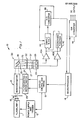
- an absorption detector 10 suitable for use with HPLC systems.
- the detector includes a xenon flashlamp 11 capable of producing radiation on a pulsed basis over a continuum within the ultraviolet and visible electromagnetic spectrum.
- a power supply and trigger circuit 12 connected to the flashlamp receives flash command pulses from an optics control and timing circuit 13. The triggering of the voltage pulses is controlled by a microprocessor 14.
- the flashlamp 11 When energized the flashlamp 11 produces a polychromatic output which enters a monochromator 15 consisting of a spherical mirror 16 and a movable diffraction grating 18 (see also Figure 2).
- the output beam of the monochromator is a wavelength band centered about the selected wavelength that corresponds to the angular position of the grating.
- This output beam is divided into two beams 25, 35 at a beam splitter 20 which directs the split beam in parallel fashion to a flow cell block 22.
- This block contains a pair of flow cells 27, 37, with the beam 25 propagating through cell 27 to a photodiode 29 and the beam 35 passing through cell 37 to a separate photodiode 39.
- Each diode output is collected by a respective charge integrator 40A, 40B and supplied to a logarithmic function circuit 42 which takes the logarithmic ratio of the two signals.
- the output of the circuit 42 is stored in a sample and hold circuit 44, converted to digital format by an analog to digital (A/D) converter 46 and read by the microprocessor 14.
- the output of the charge integrator 40A is also converted to digital form and similarly read by the microprocessor.
- the microprocessor 14 sends a command signal to the optics timing and control circuit 13 which enables the power supply and trigger circuit 12 thereby causing the xenon flashlamp 11 to produce very brief (5 microsecond), very intense (22 kilowatt) pulses of light at a rate of 10 pulses per second.
- a lens 17 forms an image of the arc produced by the flash lamp on an aperture 19 to provide an approximate point source of light.
- an order filter 21 driven by a motor 23 under control of the microprocessor can be inserted in the beam path to block wavelengths of the xenon spectrum below a cut off wavelength.
- the beam from the aperture is directed to the spherical mirror 16 which has an opaque mask 26 covering all but upper and lower reflective portions 16A, 16B respectively.
- a stepper motor 24 through an appropriate linkage (not shown) oscillates the grating 18 continuously back and forth through a range of angular positions that covers the desired usable output wavelength range of the flashlamp. One complete oscillation corresponds to two traversals of this range, one in order of ascending wavelength, the other in descending wavelength.
- the instantaneous angular position of the grating at the instant a flash occurs determines what wavelength interval will pass through the remainder of the optical system to the photodiodes 29, 39.
- the beam is diffracted by the grating and is dispersed into a spectrum of radiation, and thereafter directed to the upper reflective portion 16A of the spherical mirror which focuses a selected band of wavelengths through the beam splitter 20.
- the monochromator described above is commonly referred to as an Ebert monochromator.
- the beam splitter 20 divides the incoming beam into the two parallel output beams 25, 35 and directs these beams to the flow cell block 22. Each of these beams impinges on the block at the entrances of each of the respective flow cells 27, 37 and is transmitted therethrough.
- the cell 27 receives the sample to be analyzed and is normally connected to the outlet of a chromatographic column and thus has the column eluent flowing through it.
- the other cell 29 serves as a reference and normally contains air but may also contain a flowing fluid similar to that in the sample cell.
- the flow ceil block and related flow cells are of the design described in U.S. Patent No. 4,011,451 and include tapered flow cells to minimize the interfering effects of refractive index changes for the various liquids whose absorption characteristics are to be measured. If further details are desired on the operation of the flow cell, reference can be made to the aforementioned patent.
- the beams 25, 35 After passing through the cells 27, 37 the beams 25, 35 then strike the photodiodes 29, 39 which convert the received optical energy into an electrical signal proportional to the intensity of radiation reaching the photodiodes. Absorption of light by the sample diminishes the intensity at the sample photodiode 29 without affecting the intensity detected by the reference photodiode 39.
- the logarithmic ratio of these two signals formed in the logarithmic function circuit 42 provides an analog signal representative of the absorbance of the sample at the wavelength corresponding to the angular position of the grating. As mentioned, this signal after appropriate conversion is read by the microprocessor 14 which then supplies a corresponding analog output through a digital to analog (D/A) converter 48.
- D/A digital to analog
- the brief duration flash makes the moving grating appear to be stationary because the change in angular position of the grating 18 during the duration of the flash is extremely small. Correspondingly, the change in output wavelength due to this movement is negligible in comparison to the spectral bandwidth of the detector.
- This effect is similar to the apparent stopping of high speed motion by a stroboscope.
- the short duration of the flash effectively freezes the motion of the grating during each pulse of light, while the high instantaneous intensity output of the flashlamp 11 supplies a correspondingly high level of optical energy to the optical system.
- the system can operate at many different desired wavelengths simultaneously with enhanced signal to noise characteristics.
- This coordination function is controlled by the microprocessor 14 which provides appropriately timed signals to trigger the flash of the xenon flashlamp at the proper position of the stepping motor 24 and hence the grating.
- the microprocessor stores the absorbance signals measured at each wavelength separately and combines the respective data values to yield essentially a continuous absorbance output for each wavelength measured. Moreover, since the grating is constantly moving, it is possible to measure a plurality of distinct wavelengths without sacrificing the signal to noise ratio.
- the relationship between the position of the motor 24 as determined by the motor angle within one complete oscillation of the grating and the wavelength output can be approximated by a sinusoidal mathematical function.
- the position of the stepper motor corresponding to known locations in the spectrum can be determined.
- the actual measured correspondence between a known characteristic (e.g., peak occurrence) and the position of the stepper motor is stored in the memory of the microprocessor and is compared to a table of values representing the mathematical function for those wavelengths in the output ⁇ continuum where the measured characteristics are expected to occur.
- the motor position versus wavelength function table is appropriately adjusted with this new value to compensate for any discrepancies between theoretically derived values and actual measurements taken on the particular detector system.
- the detector is also self-calibrating.
- three features of the xenon flashlamp output energy intensity characteristics are measured, although the principles discussed can be extended to any number of measured characteristics. These are the interval between about 144 and about 185 nanometers (nm) where no energy from the flashlamp 11 reaches the photodiodes 29, 39 due to absorption by the air and the optical elements; the 185 nm point where energy is first sensed by the photodiodes; and the maximum point of the first large peak in the xenon continuum occurring at about 230 nm.
- the number of motor steps to produce one complete revolution of the grating is stored in the memory of the microprocessor 14.
- the microprocessor commands a flashpoint to occur at a predetermined number of steps from the start of a motor revolution. Since on startup the zero energy point (I 0 ) of the continuum is not known, an arbitrary motor step value is selected as the position corresponding to I 0 .
- the microprocessor also has stored motor step values corresponding to the total wavelength interval of 1 0 (e.g., 41 nm), and thus the microprocessor advances the grating and creates a flashpoint in steps that are guaranteed to be less than the I 0 interval.
- the energy reaching the reference photodiode 39 is measured and stored in memory of the microprocessor. After a complete motor revolution, the energy measurements that produced the lowest value are chosen to represent a motor position in the 1 0 interval. All subsequent energy measurements during the search mode are referenced to this motor step value.
- the procedure for locating the motor step values that corresponds to the other two measured energy intensity characteristics of the xenon flashlamp output involve similar techniques of producing flashpoints at a fixed number of motor steps from the 1 0 point and then reading the output of the reference photodiode 39. Such procedures involve techniques that are well within the skill of a knowledgeable computer programmer and form no part of the present invention and thus will not be explored in any further detail.
- a motor angle corresponding to each measured energy intensity value (e.g., the position of the 230 nm peak in the xenon flashlamp output with respect to the position of the zero energy point) is stored in the microprocessor memory. Thereafter the idealized mathematical function that relates motor step position to wavelength which is tabularized in memory is updated to correspond to the actual measured information.
- the microprocessor can command a flashpoint to occur at fixed intervals from the 1 0 point and accurately pass the wavelength of interest to the remainder of the optical system.
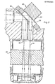
- FIG. 3 illustrates in further detail the signal detec- tion/conversion portion of the detector 10 which consists of the beam splitter 20, flow cell block 22, and photodiodes 29, 39.
- the beam splitter is integrally assembled in a housing 62 that is suitably mounted to the flow cell block at the appropriate angle to receive the output wavelength of the monochromator 15 and direct the beams 25, 35 to the sample and reference flow cells 27, 37 respectively. For the sake of clarity these beams are shown as dashed lines.
- the monochromator output beam is split in the usual manner by including a partially reflecting mirror 64 closest to the input side of the beam splitter and a fully reflecting mirror 66 parallel to and behind the mirror 64.
- a quartz rod 70 is placed in the beam path of the reference beam 35 to equalize the path length of this beam with that of the sample beam 25.
- the function of the quartz rod is to make the focal point of the reference beam co-planar with the focal point of the sample beams at the entrance window of the flow cell block.
- the quartz rod is pivotally suspended within the support structure to allow for tilting in two orthogonal directions that are in turn perpendicular to the reference beam path.
- the rod then is caused to move in two directions, i.e., into and out of the plane of the drawing figure and laterally in the plane of the figure. This feature is best illustrated in Figure 2 by the arrows adjacent the rod 70.
- the respective beams propagate through each of the cells to the photodetectors.
- the intensity appearing at the sample cell photodetector is reduced by the amount of energy absorbed by the compounds eluting from the HPLC column that are contained in the sample and an appropriate analog signal is generated by the electrical detection circuitry that is proportional to- the amount of absorbance.
Abstract
Description
- This invention relates generally to photometric apparatus, such as spectrophotometers and spectrofluorometers, and more particularly to such apparatus adapted for use as ultraviolet/visible light absorbance detectors capable of substantially simultaneous monitoring of the absorbance characteristics of fluids at more than one wavelength. Absorbance detectors of this general type are suitable for use in high performance liquid chromatography (HPLC) systems.
- The term multi-wavelength detector as applied to the art of liquid chromatography and as used throughout this specification refers to an absorbance detector that is capable of "simultaneously" detecting the absorbance characteristics of a sample solution at more than one wavelength. What is meant by the term "simultaneously" is that a series of measurements at different wavelengths are made in a sufficiently short period of time so that only slight concentration changes occur in the sample being analyzed during the period of measurement. This terminology (i.e., multi-wavelength) is to be contrasted with the terms "variable" or "tunable" wavelength detectors which imply an off-line adjustment made to the absorbance detector so that different sample runs can be analyzed at different wavelengths in the range of interest.
- In the past, ultraviolet/visible absorbance detectors have been very popular for use with HPLC systems because a significant number of compounds absorb radiation in the ultraviolet/visible range. The majority of these devices operate by analyzing a given sample solution at a single wavelength whether through use of a line emission source in combination with wavelength selective filters or a wide-range continuous source in combination with a monochromator. Problems arise with this measurement technique if some of the compounds being analyzed are only slightly absorbing at the wavelength at which the sample is irradiated. This produces an unacceptably low signal to noise ratio for those compounds.
- It should be noted that where absorbance detectors are commonly said to operate at a specific wavelength, in all cases where the source emits a continuum of radiation as opposed to line emissions at fixed wavelengths, the detector is actually operating over a wavelength interval, the extent of which is determined by the spectral bandwidth of the instrument.
- In order to improve upon the response of such single wavelength absorbance detectors, and to provide additional information with respect to the compound of interest, it has been proposed to measure absorbance of the sample at different wavelengths, and even to form a ratio of absorbances at different wavelengths, within time intervals short enough to minimize concentration changes in the sample.An example of such a multi-wavelength device is described in an article by Koichi Saltoh and Nobuo Suzuki that appeared in Analytical Chemistry, Vol. 51,
Number 11, September 1979. The spectrophotometer described there is a dual beam optical instrument capable of scanning wavelengths between 200 and 800 nanometers (nm) which employs two alternate, continuous light sources--a 30 watt deuterium and a 30 watt Tungsten lamp. The wavelength of the monochromator depends on the angular position of a diffraction grating, which is controlled by an electrically driven mo- tor/clutch arrangement. The grating is moved across the full range of the desired spectrum at a rate of either two or one Hz. A shaft encoder senses the angular position of the grating. During each scanning cycle, absorbance data at the desired wavelength is extracted by the photodetector system which includes photo multiplier tubes for appropriate amplification. The short duration during which absorbance is measured at any given wavelength results in only a very limited signal level to be recorded at the photodetectors due to the low radiated power of the lamp. This causes signal to noise ratios to be low, limiting the sensitivity of the measurement. - Another attempt to utilize multi-wavelength absorption detection is found in the Model 165 Multichannel Rapid Scanning UV-Vis Detector manufactured by Beckman Instruments. This device also is a dual beam instrument that uses a conventional deuterium lamp that is continuously energized when the instrument is operated to generate radiation over the wavelength range of interest, but rather than provide a constantly moving diffraction grating, a positioning system is used to rapidly move the grating to an assigned position corresponding to the desired wavelength. This grating position is then maintained for a sufficient period of time to receive enough radiant energy at the photodectors to obtain a usable signal level. However, the low radiant energy output of the deuterium source requires this "holding period" to be sufficiently long to severly limit the number of wavelengths at which absorbance can be measured. Furthermore, due to the short sample measurement duration available if successive measurements are to appear to be simultaneous, it is necessary that the grating be rapidly displaced to the correct position for the next wavelength at which the sample is to be monitored. Thus it is apparent this system involves overcoming a significant amount of inertia in constantly starting, driving and stopping the grating, all of which must be achieved at relatively high speeds. Such a system requires low friction mechanical components and suffers from further difficulties associated with stopping the high speed movement of the grating precisely at the required position without undergoing undesirable oscillations. Moreover, the Beckman system relies upon a closed loop servo positioner and associated sensor to accurately position the grating, all of which adds to the complexity of the detector.
- The foregoing examples of prior art multi-wavelength absorbance detectors exhibit certain fundamental operative limitations by using a continuous source in the measurement of more than one wavelength. This results in a tradeoff between the time involved in making the measurement and the amount of radiant energy received at the detector. If the measurement period is made long enough to allow sufficient energy to pass at the wavelength in question and thus increase the signal to noise ratio, either the number of wavelengths that can be measured simultaneously will be limited or fast eluting peaks will not be detected. On the other hand, short measurement period systems have low signal to noise ratios. While high-intensity pulsed sources that operate over a wide wavelength continuum have been proposed in the past (see for example U.S. Patent 3,810,696), such uses have been in single wavelength applications. Moreover an important consideration in this prior patent is to overcome the undesirable heating effects of high power, continuous radiation sources while increasing source intensity.
- The foregoing limitations of prior art absorbance detectors are overcome by the present invention. In a preferred embodiment, a multi-wavelength detector is disclosed having a diffraction grating that is continuously oscillated over the spectral range of interest and a flash tube (preferably xenon) which produces a train of high intensity, short duration flashes. Because the duration of the pulses of radiation is extremely brief (e.g., a few micro seconds) in relation to the speed of movement of the grating, a stroboscopic effect is produced which effectively freezes the motion of the grating during each pulse of light. The angular position of the grating, which is driven by a synchronous motor such as a stepper motor, determines what wavelength will be passed to the detectors. The relationship between motor position and wavelength output is approximated by a sinusoidal function and the time at which a flash occurs is synchronized by a microprocessor which stores the grating position versus output wavelength relation and correspondingly assigns a motor position value to successive wavelength intervals in the lamp spectrum.
- In accordance with other features of the embodiment, a dual beam spectrophotometer is provided wherein the source radiation is transmitted to both sample and reference cells adjacent to the detector in a manner that accurately positions each beam at identical locations on the two cells. This is achieved by including a refractive element in the optical path to one of the cells to equalize the effective beam path length with respect to that of the other cell. To align the beam on a desired segment of the reference cell, this refractive element is made adjustable to compensate for manufacturing tolerances within the instrument. Provisions are also included to calibrate the position of the motor (and hence the grating) with the desired wavelength output that utilizes the capabilities of the microprocessor and avoids the need for separate position determination means.
- Other aspects and advantages of the present invention will become apparent from the following description of illustrative examples of the invention taken in conjunction with the drawings.
-
- Figure 1 is a block diagram of a spectrophotometer built in accordance with the present invention;
- Figure 2 is a schematic, in semi-pictoral form, of the optical energy transfer portion of the system of Figure 1; and
- Figure 3 is a cross sectional view of the beam splitter and sample and reference detection cells for the system of Figure 1.
- Referring to Figure 1, there is shown an
absorption detector 10 suitable for use with HPLC systems. The detector includes axenon flashlamp 11 capable of producing radiation on a pulsed basis over a continuum within the ultraviolet and visible electromagnetic spectrum. A power supply andtrigger circuit 12 connected to the flashlamp receives flash command pulses from an optics control andtiming circuit 13. The triggering of the voltage pulses is controlled by amicroprocessor 14. - When energized the
flashlamp 11 produces a polychromatic output which enters amonochromator 15 consisting of aspherical mirror 16 and a movable diffraction grating 18 (see also Figure 2). The output beam of the monochromator is a wavelength band centered about the selected wavelength that corresponds to the angular position of the grating. This output beam is divided into twobeams beam splitter 20 which directs the split beam in parallel fashion to aflow cell block 22. This block contains a pair offlow cells beam 25 propagating throughcell 27 to aphotodiode 29 and thebeam 35 passing throughcell 37 to aseparate photodiode 39. Each diode output is collected by arespective charge integrator 40A, 40B and supplied to alogarithmic function circuit 42 which takes the logarithmic ratio of the two signals. The output of thecircuit 42 is stored in a sample andhold circuit 44, converted to digital format by an analog to digital (A/D)converter 46 and read by themicroprocessor 14. The output of the charge integrator 40A is also converted to digital form and similarly read by the microprocessor. - Considering in more detail the operation of the
detector 10, particularly the optical energy transfer within the system, reference is specifically made to Figure 2. Themicroprocessor 14 sends a command signal to the optics timing andcontrol circuit 13 which enables the power supply andtrigger circuit 12 thereby causing thexenon flashlamp 11 to produce very brief (5 microsecond), very intense (22 kilowatt) pulses of light at a rate of 10 pulses per second. Alens 17 forms an image of the arc produced by the flash lamp on anaperture 19 to provide an approximate point source of light. If desired, anorder filter 21 driven by amotor 23 under control of the microprocessor can be inserted in the beam path to block wavelengths of the xenon spectrum below a cut off wavelength. The beam from the aperture is directed to thespherical mirror 16 which has anopaque mask 26 covering all but upper and lowerreflective portions 16A, 16B respectively. Depending on whether the order filter is in or out of the beam all wavelengths produced by the source are present at and illuminate the lowerreflective portion 16B of the mirror which then reflects a substantially collimated beam of light onto thegrating 18. Astepper motor 24 through an appropriate linkage (not shown) oscillates the grating 18 continuously back and forth through a range of angular positions that covers the desired usable output wavelength range of the flashlamp. One complete oscillation corresponds to two traversals of this range, one in order of ascending wavelength, the other in descending wavelength. The instantaneous angular position of the grating at the instant a flash occurs (i.e., the flashpoint) determines what wavelength interval will pass through the remainder of the optical system to thephotodiodes beam splitter 20. The monochromator described above is commonly referred to as an Ebert monochromator. - The
beam splitter 20 divides the incoming beam into the twoparallel output beams flow cell block 22. Each of these beams impinges on the block at the entrances of each of therespective flow cells cell 27 receives the sample to be analyzed and is normally connected to the outlet of a chromatographic column and thus has the column eluent flowing through it. Theother cell 29 serves as a reference and normally contains air but may also contain a flowing fluid similar to that in the sample cell. The flow ceil block and related flow cells are of the design described in U.S. Patent No. 4,011,451 and include tapered flow cells to minimize the interfering effects of refractive index changes for the various liquids whose absorption characteristics are to be measured. If further details are desired on the operation of the flow cell, reference can be made to the aforementioned patent. - After passing through the
cells beams photodiodes sample photodiode 29 without affecting the intensity detected by thereference photodiode 39. The logarithmic ratio of these two signals formed in thelogarithmic function circuit 42 provides an analog signal representative of the absorbance of the sample at the wavelength corresponding to the angular position of the grating. As mentioned, this signal after appropriate conversion is read by themicroprocessor 14 which then supplies a corresponding analog output through a digital to analog (D/A)converter 48. - The brief duration flash makes the moving grating appear to be stationary because the change in angular position of the grating 18 during the duration of the flash is extremely small. Correspondingly, the change in output wavelength due to this movement is negligible in comparison to the spectral bandwidth of the detector. This effect is similar to the apparent stopping of high speed motion by a stroboscope. In this instance, the short duration of the flash effectively freezes the motion of the grating during each pulse of light, while the high instantaneous intensity output of the
flashlamp 11 supplies a correspondingly high level of optical energy to the optical system. Thus it is apparent that by properly coordinating the timing of the flash to the motion of the grating, the system can operate at many different desired wavelengths simultaneously with enhanced signal to noise characteristics. This coordination function is controlled by themicroprocessor 14 which provides appropriately timed signals to trigger the flash of the xenon flashlamp at the proper position of the steppingmotor 24 and hence the grating. The microprocessor stores the absorbance signals measured at each wavelength separately and combines the respective data values to yield essentially a continuous absorbance output for each wavelength measured. Moreover, since the grating is constantly moving, it is possible to measure a plurality of distinct wavelengths without sacrificing the signal to noise ratio. - An important feature of the coordination between the grating position and the flashpoint of the lamp rests in the ability of the detector to calibrate itself with respect to the relationship between the position of the
stepper motor 24 and the wavelength of the system. Because the detector system of the embodiment being described does not include a distinct grating position sensor, there is no direct sensing of the position of the stepper motor and thus the angular position of grating. Therefore, the position of the stepper motor must be determined. Once this is done, the position of themotor 24 that corresponds to any given wavelength is known. This is done by taking advantage of the wavelength structure of the flashlamp output whose output continuum is zero below a certain lower wavelength limit and which has several distinctive peak emissions superimposed on a gently varying background. These peaks occur at certain repeatable characteristic wavelengths over the spectrum produced by the flashlamp. - The relationship between the position of the
motor 24 as determined by the motor angle within one complete oscillation of the grating and the wavelength output can be approximated by a sinusoidal mathematical function. By utilizing the microprocessor to find and recognize certain characteristics of the xenon flashlamp spectrum by reading the output of the photodiodes, the position of the stepper motor corresponding to known locations in the spectrum can be determined. The actual measured correspondence between a known characteristic (e.g., peak occurrence) and the position of the stepper motor is stored in the memory of the microprocessor and is compared to a table of values representing the mathematical function for those wavelengths in the output ·continuum where the measured characteristics are expected to occur. The motor position versus wavelength function table is appropriately adjusted with this new value to compensate for any discrepancies between theoretically derived values and actual measurements taken on the particular detector system. Thus, the detector is also self-calibrating. - For the embodiment being described, three features of the xenon flashlamp output energy intensity characteristics are measured, although the principles discussed can be extended to any number of measured characteristics. These are the interval between about 144 and about 185 nanometers (nm) where no energy from the
flashlamp 11 reaches thephotodiodes - The number of motor steps to produce one complete revolution of the grating is stored in the memory of the
microprocessor 14. The microprocessor commands a flashpoint to occur at a predetermined number of steps from the start of a motor revolution. Since on startup the zero energy point (I0) of the continuum is not known, an arbitrary motor step value is selected as the position corresponding to I0. The microprocessor also has stored motor step values corresponding to the total wavelength interval of 10 (e.g., 41 nm), and thus the microprocessor advances the grating and creates a flashpoint in steps that are guaranteed to be less than the I0 interval. The energy reaching thereference photodiode 39 is measured and stored in memory of the microprocessor. After a complete motor revolution, the energy measurements that produced the lowest value are chosen to represent a motor position in the 10 interval. All subsequent energy measurements during the search mode are referenced to this motor step value. - The procedure for locating the motor step values that corresponds to the other two measured energy intensity characteristics of the xenon flashlamp output involve similar techniques of producing flashpoints at a fixed number of motor steps from the 10 point and then reading the output of the
reference photodiode 39. Such procedures involve techniques that are well within the skill of a knowledgeable computer programmer and form no part of the present invention and thus will not be explored in any further detail. - When the search mode has been completed, a motor angle corresponding to each measured energy intensity value (e.g., the position of the 230 nm peak in the xenon flashlamp output with respect to the position of the zero energy point) is stored in the microprocessor memory. Thereafter the idealized mathematical function that relates motor step position to wavelength which is tabularized in memory is updated to correspond to the actual measured information. Thus the microprocessor can command a flashpoint to occur at fixed intervals from the 10 point and accurately pass the wavelength of interest to the remainder of the optical system.
- Figure 3 illustrates in further detail the signal detec- tion/conversion portion of the
detector 10 which consists of thebeam splitter 20,flow cell block 22, andphotodiodes housing 62 that is suitably mounted to the flow cell block at the appropriate angle to receive the output wavelength of themonochromator 15 and direct thebeams reference flow cells mirror 64 closest to the input side of the beam splitter and a fully reflectingmirror 66 parallel to and behind themirror 64. - Since the intensity between successive flashes of the
pulsed xenon flashlamp 11 can vary, the use of a dual beam system where energy is transmitted both to a sample and a reference cell is useful in compensating for the above variations in intensity of the source. Due to size constraints and other limitations placed upon mechanical tolerances within commercial absorbance detector instruments, difficulties arise in precisely matching each of the two beams which result in reduced signal to noise performance. - Thus a
quartz rod 70 is placed in the beam path of thereference beam 35 to equalize the path length of this beam with that of thesample beam 25. In other words, the function of the quartz rod is to make the focal point of the reference beam co-planar with the focal point of the sample beams at the entrance window of the flow cell block. In order to compensate for any misalignment of the various optical components, the quartz rod is pivotally suspended within the support structure to allow for tilting in two orthogonal directions that are in turn perpendicular to the reference beam path. The rod then is caused to move in two directions, i.e., into and out of the plane of the drawing figure and laterally in the plane of the figure. This feature is best illustrated in Figure 2 by the arrows adjacent therod 70. Thus it is possible to shift the beam position to coincide with a predetermined location of the reference cell beam entrance window corresponding to a similar location in the sample cell beam entrance window. - Thereafter, the respective beams propagate through each of the cells to the photodetectors. The intensity appearing at the sample cell photodetector is reduced by the amount of energy absorbed by the compounds eluting from the HPLC column that are contained in the sample and an appropriate analog signal is generated by the electrical detection circuitry that is proportional to- the amount of absorbance.
- Although a preferred embodiment has been set forth in detail above, this is solely for the purpose of illustration as modifications will become apparent to those of skill in the art. For example, the embodiment has been described as operating without the need for a separate positioning system to determine grating position; however, the principles of the present invention can be extended to encompass the inclusion of a position sensor such as a shaft encoder or the like and an appropriate servo-positioner to locate the continuously operated grating at preselected angular positions that are synchronized with the occurrence of a flash. Additionally, the optical excitation means disclosed has been illustrated as operating with an absorbance detector, but these means are equally applicable to a spectrofluorometer. Thus the invention is to be limited only by the scope of the appended claims.
Claims (20)
Applications Claiming Priority (2)
| Application Number | Priority Date | Filing Date | Title |
|---|---|---|---|
| US06/553,736 US4565447A (en) | 1983-11-21 | 1983-11-21 | Photometric apparatus with multi-wavelength excitation |
| US553736 | 1983-11-21 |
Publications (3)
| Publication Number | Publication Date |
|---|---|
| EP0146781A2 true EP0146781A2 (en) | 1985-07-03 |
| EP0146781A3 EP0146781A3 (en) | 1986-04-16 |
| EP0146781B1 EP0146781B1 (en) | 1989-03-15 |
Family
ID=24210543
Family Applications (1)
| Application Number | Title | Priority Date | Filing Date |
|---|---|---|---|
| EP84113990A Expired EP0146781B1 (en) | 1983-11-21 | 1984-11-19 | Photometric apparatus with multi-wavelength excitation |
Country Status (4)
| Country | Link |
|---|---|
| US (1) | US4565447A (en) |
| EP (1) | EP0146781B1 (en) |
| JP (1) | JPS60259918A (en) |
| DE (1) | DE3477263D1 (en) |
Cited By (3)
| Publication number | Priority date | Publication date | Assignee | Title |
|---|---|---|---|---|
| EP0211411A2 (en) * | 1985-08-09 | 1987-02-25 | Sato Pharmaceutical Research Institute Limited | Method and apparatus for performing novel high-performance liquid chromatography |
| EP0493524A1 (en) * | 1989-09-22 | 1992-07-08 | Agmed Inc. | Soil test apparatus |
| EP3421987A1 (en) * | 2017-06-26 | 2019-01-02 | ARKRAY, Inc. | Liquid chromatography device comprising a flow cell |
Families Citing this family (25)
| Publication number | Priority date | Publication date | Assignee | Title |
|---|---|---|---|---|
| US4838691A (en) * | 1985-07-10 | 1989-06-13 | Beckman Instruments, Inc. | Method and apparatus for determining calibration accuracy of a scientific instrument |
| JPH01155221A (en) * | 1987-12-14 | 1989-06-19 | Shimadzu Corp | Wavelength scanning method of spectrophotometer |
| US5014216A (en) * | 1988-07-19 | 1991-05-07 | Beckman Instruments, Inc. | Concentration determination with multiple wavelength flash photometers |
| US5092677A (en) * | 1989-08-02 | 1992-03-03 | Artel, Inc. | Photometer having a long lamp life, reduced warm-up period and resonant frequency mixing |
| US5148239A (en) * | 1990-07-17 | 1992-09-15 | Rainin Instrument Co., Inc. | High performance absorbance detector with flashlamp and compact folded optics system |
| KR960016331B1 (en) * | 1990-08-29 | 1996-12-09 | 가부시끼가이샤 시마즈 세이사구쇼 | Absorbance detector |
| US5407638A (en) * | 1993-04-28 | 1995-04-18 | Shell Oil Company | Detector-cell adapted for continuous-flow absorption detection |
| US5408326A (en) * | 1993-04-28 | 1995-04-18 | Shell Oil Company | Dual-wavelength absorption detector adapted for continuous-flow detection |
| SE9600747D0 (en) * | 1996-02-27 | 1996-02-27 | Pharmacia Biotech Ab | Calibration method |
| US5923482A (en) * | 1997-03-14 | 1999-07-13 | Waters Investments Limited | Changing astigmatism in an optical system |
| AUPP748398A0 (en) * | 1998-12-03 | 1998-12-24 | Varian Australia Pty Ltd | Uv-vis spectrophotometry |
| EP1156310A1 (en) * | 1999-12-31 | 2001-11-21 | Acterna Eningen GmbH | Optical reference cell and method for calibrating a spectrometer |
| US6670617B2 (en) * | 2001-06-28 | 2003-12-30 | Ondeo Nalco Company | Mirror fluorometer |
| US6741348B2 (en) * | 2002-04-29 | 2004-05-25 | The Curators Of The University Of Missouri | Ultrasensitive spectrophotometer |
| JP2004077212A (en) * | 2002-08-13 | 2004-03-11 | Agilent Technol Inc | Device for measuring wavelength and waveform of optical signal |
| US7268881B2 (en) * | 2004-02-17 | 2007-09-11 | The Curators Of The University Of Missouri | Light scattering detector |
| US7903252B2 (en) * | 2005-01-13 | 2011-03-08 | The Curators Of The University Of Missouri | Noise cancellation in fourier transform spectrophotometry |
| US7262844B2 (en) * | 2005-01-13 | 2007-08-28 | The Curators Of The University Of Missouri | Ultrasensitive spectrophotometer |
| AU2007222018A1 (en) | 2006-03-09 | 2007-09-13 | Alltech Associates, Inc. | Evaporative light scattering detector |
| DE102006016855A1 (en) * | 2006-04-07 | 2007-10-11 | Emerson Process Management Gmbh & Co. Ohg | Method and device for measuring the optical absorption of samples |
| CN104251911B (en) | 2008-02-05 | 2017-05-31 | 普凯尔德诊断技术有限公司 | System for identifying bacterium in biological sample |
| WO2009152321A1 (en) * | 2008-06-11 | 2009-12-17 | The Curators Of The University Of Missouri | Liquid chromatography detector and flow controller therefor |
| US8309897B2 (en) * | 2009-02-06 | 2012-11-13 | Pocared Diagnostics Ltd. | Optical measurement arrangement |
| US10288632B2 (en) | 2009-09-21 | 2019-05-14 | Pocared Diagnostics Ltd. | System for conducting the identification of bacteria in biological samples |
| US9862920B2 (en) | 2012-12-11 | 2018-01-09 | Pocared Diagnostics Ltd. | Optics cup with curved bottom |
Citations (5)
| Publication number | Priority date | Publication date | Assignee | Title |
|---|---|---|---|---|
| US3843259A (en) * | 1972-12-11 | 1974-10-22 | Hitachi Ltd | Differential spectrophotometer |
| DE2415049A1 (en) * | 1974-03-13 | 1975-09-18 | Schoeffel Instrument Corp | MULTI-CHANNEL ANALYZER FOR THE OPTICAL MEASUREMENT OF FRACTIONS RECEIVED IN THE CHROMATOGRAPHY OF LIQUIDS |
| US3985442A (en) * | 1974-06-07 | 1976-10-12 | Gte Sylvania Incorporated | Data acquisition system for spectrophotometer |
| US4285596A (en) * | 1977-08-16 | 1981-08-25 | Neotec Corporation | Holographic diffraction grating system for rapid scan spectral analysis |
| EP0121404A2 (en) * | 1983-03-29 | 1984-10-10 | Kabushiki Kaisha Toshiba | A photometric light absorption measuring apparatus |
Family Cites Families (6)
| Publication number | Priority date | Publication date | Assignee | Title |
|---|---|---|---|---|
| JPS5423279B1 (en) * | 1969-04-01 | 1979-08-13 | ||
| US3765769A (en) * | 1972-04-26 | 1973-10-16 | United Aircraft Corp | Dynamic spectroscopy of picosecond pulses |
| US3810696A (en) * | 1973-02-20 | 1974-05-14 | Waters Associates Inc | Improved analytical apparatus for measuring light absorbance of fluids |
| US4322807A (en) * | 1980-03-07 | 1982-03-30 | The Perkin-Elmer Corporation | Safe memory system for a spectrophotometer |
| JPS57139647A (en) * | 1981-02-23 | 1982-08-28 | Shimadzu Corp | Chromatograph detecting device |
| US4464051A (en) * | 1982-03-02 | 1984-08-07 | The Perkin-Elmer Corporation | Spectrophotometer |
-
1983
- 1983-11-21 US US06/553,736 patent/US4565447A/en not_active Expired - Fee Related
-
1984
- 1984-11-19 EP EP84113990A patent/EP0146781B1/en not_active Expired
- 1984-11-19 DE DE8484113990T patent/DE3477263D1/en not_active Expired
- 1984-11-21 JP JP59244702A patent/JPS60259918A/en active Granted
Patent Citations (5)
| Publication number | Priority date | Publication date | Assignee | Title |
|---|---|---|---|---|
| US3843259A (en) * | 1972-12-11 | 1974-10-22 | Hitachi Ltd | Differential spectrophotometer |
| DE2415049A1 (en) * | 1974-03-13 | 1975-09-18 | Schoeffel Instrument Corp | MULTI-CHANNEL ANALYZER FOR THE OPTICAL MEASUREMENT OF FRACTIONS RECEIVED IN THE CHROMATOGRAPHY OF LIQUIDS |
| US3985442A (en) * | 1974-06-07 | 1976-10-12 | Gte Sylvania Incorporated | Data acquisition system for spectrophotometer |
| US4285596A (en) * | 1977-08-16 | 1981-08-25 | Neotec Corporation | Holographic diffraction grating system for rapid scan spectral analysis |
| EP0121404A2 (en) * | 1983-03-29 | 1984-10-10 | Kabushiki Kaisha Toshiba | A photometric light absorption measuring apparatus |
Cited By (5)
| Publication number | Priority date | Publication date | Assignee | Title |
|---|---|---|---|---|
| EP0211411A2 (en) * | 1985-08-09 | 1987-02-25 | Sato Pharmaceutical Research Institute Limited | Method and apparatus for performing novel high-performance liquid chromatography |
| EP0211411A3 (en) * | 1985-08-09 | 1989-05-31 | Sato Pharmaceutical Research Institute Limited | Method and apparatus for performing novel high-performance liquid chromatography |
| EP0493524A1 (en) * | 1989-09-22 | 1992-07-08 | Agmed Inc. | Soil test apparatus |
| EP0493524A4 (en) * | 1989-09-22 | 1992-12-02 | Agmed Inc. | Soil test apparatus |
| EP3421987A1 (en) * | 2017-06-26 | 2019-01-02 | ARKRAY, Inc. | Liquid chromatography device comprising a flow cell |
Also Published As
| Publication number | Publication date |
|---|---|
| US4565447A (en) | 1986-01-21 |
| JPS60259918A (en) | 1985-12-23 |
| DE3477263D1 (en) | 1989-04-20 |
| JPH056651B2 (en) | 1993-01-27 |
| EP0146781B1 (en) | 1989-03-15 |
| EP0146781A3 (en) | 1986-04-16 |
Similar Documents
| Publication | Publication Date | Title |
|---|---|---|
| US4565447A (en) | Photometric apparatus with multi-wavelength excitation | |
| US3985441A (en) | Multi-channel spectral analyzer for liquid chromatographic separations | |
| US4371785A (en) | Method and apparatus for detection and analysis of fluids | |
| US4123172A (en) | Comparison type colorimeter | |
| US4781456A (en) | Absorption photometer | |
| EP0243447A4 (en) | Nondispersive gas analyzer having no moving parts. | |
| US3437411A (en) | Optical null spectrophotometer | |
| US4223995A (en) | Calibration system for spectrophotometers | |
| CA2051398A1 (en) | Wavelength detecting apparatus | |
| EP0798559B1 (en) | Method of detecting sample substances and fluorescence spectrometer using the method | |
| US4563585A (en) | Monitoring gas and vapor concentrations | |
| US4491730A (en) | Method and apparatus for feedback stabilized photometric detection in fluids | |
| JPH052931B2 (en) | ||
| US4577105A (en) | Method of determining masses of absorbing components of a sample in a test volume and a device for implementation of this method | |
| JPS5985918A (en) | Direct ratio type spectrophotometer | |
| US4035086A (en) | Multi-channel analyzer for liquid chromatographic separations | |
| EP0081947A1 (en) | Method and apparatus for normalizing radiometric measurements | |
| US3937576A (en) | Illumination system for an atomic absorption spectral photometer | |
| JPS6038209Y2 (en) | analyzer | |
| USRE27270E (en) | Null type comparison eeflectometer wherein nulling is accomplished by moving the light detector | |
| US3463596A (en) | Null type comparison reflectometer wherein nulling is accomplished by moving the light detector | |
| SU730066A1 (en) | Atomic flu orescent analyzer | |
| JPS6321850B2 (en) | ||
| JPH06241900A (en) | Spectrochemical analyzer | |
| Flaschka et al. | Photometric titrations—XII: A full-immersion spectrophotometer |
Legal Events
| Date | Code | Title | Description |
|---|---|---|---|
| PUAI | Public reference made under article 153(3) epc to a published international application that has entered the european phase |
Free format text: ORIGINAL CODE: 0009012 |
|
| AK | Designated contracting states |
Designated state(s): CH DE FR GB LI NL SE |
|
| PUAL | Search report despatched |
Free format text: ORIGINAL CODE: 0009013 |
|
| AK | Designated contracting states |
Kind code of ref document: A3 Designated state(s): CH DE FR GB LI NL SE |
|
| 17P | Request for examination filed |
Effective date: 19860521 |
|
| 17Q | First examination report despatched |
Effective date: 19880223 |
|
| GRAA | (expected) grant |
Free format text: ORIGINAL CODE: 0009210 |
|
| AK | Designated contracting states |
Kind code of ref document: B1 Designated state(s): CH DE FR GB LI NL SE |
|
| REF | Corresponds to: |
Ref document number: 3477263 Country of ref document: DE Date of ref document: 19890420 |
|
| ET | Fr: translation filed | ||
| PLBE | No opposition filed within time limit |
Free format text: ORIGINAL CODE: 0009261 |
|
| STAA | Information on the status of an ep patent application or granted ep patent |
Free format text: STATUS: NO OPPOSITION FILED WITHIN TIME LIMIT |
|
| 26N | No opposition filed | ||
| PGFP | Annual fee paid to national office [announced via postgrant information from national office to epo] |
Ref country code: SE Payment date: 19911016 Year of fee payment: 8 |
|
| PGFP | Annual fee paid to national office [announced via postgrant information from national office to epo] |
Ref country code: NL Payment date: 19911130 Year of fee payment: 8 |
|
| PG25 | Lapsed in a contracting state [announced via postgrant information from national office to epo] |
Ref country code: SE Effective date: 19921120 |
|
| PG25 | Lapsed in a contracting state [announced via postgrant information from national office to epo] |
Ref country code: NL Effective date: 19930601 |
|
| NLV4 | Nl: lapsed or anulled due to non-payment of the annual fee | ||
| REG | Reference to a national code |
Ref country code: CH Ref legal event code: PUE Owner name: WATERS INVESTMENTS LIMITED |
|
| EUG | Se: european patent has lapsed |
Ref document number: 84113990.0 Effective date: 19930610 |
|
| REG | Reference to a national code |
Ref country code: GB Ref legal event code: 732E |
|
| REG | Reference to a national code |
Ref country code: FR Ref legal event code: TP |
|
| PGFP | Annual fee paid to national office [announced via postgrant information from national office to epo] |
Ref country code: FR Payment date: 19961021 Year of fee payment: 13 |
|
| PGFP | Annual fee paid to national office [announced via postgrant information from national office to epo] |
Ref country code: GB Payment date: 19961025 Year of fee payment: 13 |
|
| PGFP | Annual fee paid to national office [announced via postgrant information from national office to epo] |
Ref country code: DE Payment date: 19961028 Year of fee payment: 13 |
|
| PGFP | Annual fee paid to national office [announced via postgrant information from national office to epo] |
Ref country code: CH Payment date: 19961030 Year of fee payment: 13 |
|
| PG25 | Lapsed in a contracting state [announced via postgrant information from national office to epo] |
Ref country code: GB Free format text: LAPSE BECAUSE OF NON-PAYMENT OF DUE FEES Effective date: 19971119 |
|
| PG25 | Lapsed in a contracting state [announced via postgrant information from national office to epo] |
Ref country code: LI Free format text: LAPSE BECAUSE OF NON-PAYMENT OF DUE FEES Effective date: 19971130 Ref country code: FR Free format text: THE PATENT HAS BEEN ANNULLED BY A DECISION OF A NATIONAL AUTHORITY Effective date: 19971130 Ref country code: CH Free format text: LAPSE BECAUSE OF NON-PAYMENT OF DUE FEES Effective date: 19971130 |
|
| GBPC | Gb: european patent ceased through non-payment of renewal fee |
Effective date: 19971119 |
|
| REG | Reference to a national code |
Ref country code: CH Ref legal event code: PL |
|
| PG25 | Lapsed in a contracting state [announced via postgrant information from national office to epo] |
Ref country code: DE Free format text: LAPSE BECAUSE OF NON-PAYMENT OF DUE FEES Effective date: 19980801 |
|
| REG | Reference to a national code |
Ref country code: FR Ref legal event code: ST |