EP0146347A2 - Devices for spinal fixation - Google Patents
Devices for spinal fixation Download PDFInfo
- Publication number
- EP0146347A2 EP0146347A2 EP84308681A EP84308681A EP0146347A2 EP 0146347 A2 EP0146347 A2 EP 0146347A2 EP 84308681 A EP84308681 A EP 84308681A EP 84308681 A EP84308681 A EP 84308681A EP 0146347 A2 EP0146347 A2 EP 0146347A2
- Authority
- EP
- European Patent Office
- Prior art keywords
- sides
- shorter
- rectangle
- spine
- bent
- Prior art date
- Legal status (The legal status is an assumption and is not a legal conclusion. Google has not performed a legal analysis and makes no representation as to the accuracy of the status listed.)
- Granted
Links
Images

Classifications
-
- A—HUMAN NECESSITIES
- A61—MEDICAL OR VETERINARY SCIENCE; HYGIENE
- A61B—DIAGNOSIS; SURGERY; IDENTIFICATION
- A61B17/00—Surgical instruments, devices or methods, e.g. tourniquets
- A61B17/56—Surgical instruments or methods for treatment of bones or joints; Devices specially adapted therefor
- A61B17/58—Surgical instruments or methods for treatment of bones or joints; Devices specially adapted therefor for osteosynthesis, e.g. bone plates, screws, setting implements or the like
- A61B17/68—Internal fixation devices, including fasteners and spinal fixators, even if a part thereof projects from the skin
- A61B17/70—Spinal positioners or stabilisers ; Bone stabilisers comprising fluid filler in an implant
- A61B17/7053—Spinal positioners or stabilisers ; Bone stabilisers comprising fluid filler in an implant with parts attached to bones or to each other by flexible wires, straps, sutures or cables
Definitions
- This invention relates to devices for spinal fixation, of which one known type consists of stainless steel round rod formed by bending and homogeneously welding into a rectangle adapted to fit neatly on the posterior surface of the spine and embrace two or more bones between its shorter sides with its longer sides substantially parallel to the length of the bones, the rectangle being fixed in place to immobilise the embraced bones with respect to each other by means of wires around or looped through the rectangle and passing through holes in the bones.
- the object of the invention is to provide improved devices for spinal fixation.
- a device for spinal fixation consists of rod of biocompatible material formed into a rigid rectangle with its shorter sides bent (e.g. into or including a curve) in the same direction from the plane of the longer sides.
- the bending (and/or curving) of the shorter sides enables the "roofed” rectangle to fit more closely upon the spine than the previously “flat” rectangle and therefore it appears less bulky. This reduces dead spaces between the device and the spine, thus effectively reducing the risk of haematoma and infection, whilst being biomechanically more efficient. Correct fixing of the "roofed” rectangle is more consistently obtained because wires or other strands looped through the rectangle round the shorter sides are automatically guided down the "slopes" of the shorter sides to rest at the corners formed with the longer sides. Furthermore, because the "roofed” rectangle makes a better fit and affords greater inherent torsional rigidity than a flat rectangle, it gives much greater control of rotation of the immobilised bones with respect to the remainder of the spine.
- the "roofed” rectangle is the first implanted device to give the spine effective torsional rigidity, therefore allowing immediate mobilisation following surgery, without the need of any external cast or brace.
- the shorter sides preferably lie in parallel planes, perpendicular to the plane of the longer sides, and each shorter side preferably has two straight portions, at an angle to each other of between 90° and 110 0 , with a small radius curve between them and small radius curves at the corners formed with the longer sides.
- the "roofed" rectangle may be formed of 3/16" diameter stainless steel rod with radiused curves and homogeneously joined, but it may alternatively be formed of titanium rod.
- a "roofed" rectangle of appreciable length may be provided with at least one crossbar between the longer sides, the crossbar being bent similarily to the shorter sides and in the same direction.
- Such a crossbar may have tubular ends slidable along the longer sides, to allow for adjustment to suit intermediate bones.
- any of the sides of the "roofed” rectangle, or a crossbar thereon, may be provided with at least one integral pierced lug or "eye” for a fixation screw or pin.
- the shorter sides may have different "roof” angles, to suit different sizes of bones and/or bone combinations.
- a device for spinal fixation consists of rod of biocompatible material formed into a rigid U-shape with a base portion shorter than parallel sides of the U, and with the base portion bent (e.g. into or including a curve) from the plane of the sides.
- the bending (and/or curving) of the base portion of the U enables it to fit closely at one position on a spine of an infant or juvenile and be wired thereto, whilst the sides of the U extend parallel to the spine, which may be wired or tied with other strands slidably thereto, or to at least one crossbar bent (and/or curved) similarly to and in the same direction as the base portion of the U between parallel tubular portions slidable along the sides of the U, to allow for growth of the spine whilst maintaining support therefor.
- the base portion of the U preferably has two straight portions at an angle to each other of between 90° and 110°, with a small radius curve between them and small radius curves at the corners formed with the sides of the U
- the "roofed" U may be formed of 3/16" diameter stainless steel rod with radiussed curves, and has the advantage of not requiring any welding, but it may alternatively be formed of titanium rod.
- the base portions may have different "roof” angles, to suit different sizes of bones and/or bone combinations.
- Either of the sides or the base of the "roofed” U, or a crossbar slidable thereon, may be provided with at least one integral pierced lug or "eye” for a fixation screw or pin.
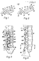
- the spinal fixation devices shown in Figures 1 to 5 each consist of rod of biocompatible material (e.g., stainless steel or titanium of 3/16" diameter) formed into a rigid rectangle with its shorter sides 11 bent in the same direction from the plane of the longer sides 12.
- the shorter sides 11 lie in parallel planes perpendicular to the plane of the longer sides 12, and each shorter side 11 has two straight portions 13 at an angle to each other of 100°, with a small radius curve 14 between them and small radius curves 15 at the corners formed with the longer sides.
- a "roofed" rectangle of greater length than those of Figures 1 and 2, and comparable with that of Figures 3 and 4, is provided with a pair of fixed crossbars 17 between the longer sides 12, the crossbars being bent similarly to the shorter sides 11 and in the same direction.
- the "roofed" rectangle shown in Figure 7 is similar to that of Figure 2 but is provided with a pierced lug or "eye” 18 integral with one longer side 12 and a pair of pierced lugs or “eyes” 18X integral with one shorter side, for additional fixing by means of fixation screws or pins (not shown).
- the spinal fixation device shown in Figure 8 consists of rod of biocompatible material (e.g., stainless steel or titanium of 3/16" diameter) formed into a rigid U-shape with a base portion 21 shorter than parallel sides 22 of the U, and with the base portion 21 bent in a plane perpendicular to the plane of the sides 22, with two straight portions 23 at an angle to each other of 100 0 , with a small radius curve 24 between them and small radius curves 25 at the corners formed with the sides 22.
- biocompatible material e.g., stainless steel or titanium of 3/16" diameter
- the bending of the base portion 21 of the U enables it to fit closely at one position on a spine (not shown) of an infant or juvenile and be wired thereto, whilst the sides 22 of the U extend parallel to the spine, being slidably wired thereto to allow for growth of the spine whilst maintaining support theref or.
- a crossbar 27 bent similarly to and in the same direction as the base portion 21 of the U may be provided between parallel tubular portions 26 slidable along the sides 22 of the U.
- two slidable crossbars may be provided by having one crossbar 27X provided with tubular portions 26X open at each end, the other crossbar 27Y being formed by a U-shaped member similar to the basic U-shaped fixation device, with the sides 22Y slidable in the opposite ends of the tubular portions 26X to the sides 22 of the basic fixation device.
Abstract
Description
- This invention relates to devices for spinal fixation, of which one known type consists of stainless steel round rod formed by bending and homogeneously welding into a rectangle adapted to fit neatly on the posterior surface of the spine and embrace two or more bones between its shorter sides with its longer sides substantially parallel to the length of the bones, the rectangle being fixed in place to immobilise the embraced bones with respect to each other by means of wires around or looped through the rectangle and passing through holes in the bones.
- The object of the invention is to provide improved devices for spinal fixation.
- According to one aspect of the present invention, a device for spinal fixation consists of rod of biocompatible material formed into a rigid rectangle with its shorter sides bent (e.g. into or including a curve) in the same direction from the plane of the longer sides.
- The bending (and/or curving) of the shorter sides enables the "roofed" rectangle to fit more closely upon the spine than the previously "flat" rectangle and therefore it appears less bulky. This reduces dead spaces between the device and the spine, thus effectively reducing the risk of haematoma and infection, whilst being biomechanically more efficient. Correct fixing of the "roofed" rectangle is more consistently obtained because wires or other strands looped through the rectangle round the shorter sides are automatically guided down the "slopes" of the shorter sides to rest at the corners formed with the longer sides. Furthermore, because the "roofed" rectangle makes a better fit and affords greater inherent torsional rigidity than a flat rectangle, it gives much greater control of rotation of the immobilised bones with respect to the remainder of the spine.
- The "roofed" rectangle is the first implanted device to give the spine effective torsional rigidity, therefore allowing immediate mobilisation following surgery, without the need of any external cast or brace.
- The shorter sides preferably lie in parallel planes, perpendicular to the plane of the longer sides, and each shorter side preferably has two straight portions, at an angle to each other of between 90° and 1100, with a small radius curve between them and small radius curves at the corners formed with the longer sides. Thus the "roofed" rectangle may be formed of 3/16" diameter stainless steel rod with radiused curves and homogeneously joined, but it may alternatively be formed of titanium rod.
- A "roofed" rectangle of appreciable length may be provided with at least one crossbar between the longer sides, the crossbar being bent similarily to the shorter sides and in the same direction. Such a crossbar may have tubular ends slidable along the longer sides, to allow for adjustment to suit intermediate bones.
- Any of the sides of the "roofed" rectangle, or a crossbar thereon, may be provided with at least one integral pierced lug or "eye" for a fixation screw or pin.
- In addition to providing "roofed" rectangles of different lengths and/or widths, the shorter sides may have different "roof" angles, to suit different sizes of bones and/or bone combinations.
- According to another aspect of the present invention, a device for spinal fixation consists of rod of biocompatible material formed into a rigid U-shape with a base portion shorter than parallel sides of the U, and with the base portion bent (e.g. into or including a curve) from the plane of the sides.
- The bending (and/or curving) of the base portion of the U enables it to fit closely at one position on a spine of an infant or juvenile and be wired thereto, whilst the sides of the U extend parallel to the spine, which may be wired or tied with other strands slidably thereto, or to at least one crossbar bent (and/or curved) similarly to and in the same direction as the base portion of the U between parallel tubular portions slidable along the sides of the U, to allow for growth of the spine whilst maintaining support therefor.
- The base portion of the U preferably has two straight portions at an angle to each other of between 90° and 110°, with a small radius curve between them and small radius curves at the corners formed with the sides of the U Thus the "roofed" U may be formed of 3/16" diameter stainless steel rod with radiussed curves, and has the advantage of not requiring any welding, but it may alternatively be formed of titanium rod.
- In addition to providing "roofed" U's of different lengths and/or widths, the base portions may have different "roof" angles, to suit different sizes of bones and/or bone combinations.
- Either of the sides or the base of the "roofed" U, or a crossbar slidable thereon, may be provided with at least one integral pierced lug or "eye" for a fixation screw or pin.
- A number of embodiments of the invention will now be described, by way of example only, with reference to the accompanying drawings, in which:-
- Figures 1 and 2 are perspective views of two sizes of rectangular spinal fixation device in accordance with the invention;
- Figure 3 is a perspective view showing a similar but even longer rectangular spinal fixation device than in Figure 2 wired in place to the sacrum and adjacent lumbar vertebrae;
- Figure 4 is a fragmentary side elevation of Figure 3 to a slightly larger scale;
- Figure 5 is a section from the line V-V of Figure 4;
- Figure 6 is a perspective view of another rectangular spinal fixation device in accordance with the invention having two fixed intermediate crossbars;
- Figure 7 is a plan of a rectangular spinal fixation device similar to that of Figure 2 but having integral pierced lugs or "eyes";
- Figure 8 is a perspective view of a U-shaped spinal fixation device in accordance with the invention;
- Figure 9 corresponds to Figure 8 but shows a U-shaped spinal fixation device provided with an adjustable sliding crossbar; and
- Figure 10 also corresponds to Figure 8 but shows two slidable crossbars.
- The spinal fixation devices shown in Figures 1 to 5 each consist of rod of biocompatible material (e.g., stainless steel or titanium of 3/16" diameter) formed into a rigid rectangle with its
shorter sides 11 bent in the same direction from the plane of thelonger sides 12. Theshorter sides 11 lie in parallel planes perpendicular to the plane of thelonger sides 12, and eachshorter side 11 has twostraight portions 13 at an angle to each other of 100°, with asmall radius curve 14 between them andsmall radius curves 15 at the corners formed with the longer sides. - The bending and curving of the
shorter sides 11 enables such a "roofed" rectangle to fit more closely upon the spine than a "flat" rectangle and therefore it appears less bulky, as will be appreciated from reference to Figures 4 and 5, thus reducing dead spaces between the device and the spine, with accompanying reduction in the risk of haematoma and infection. Correct fixing of the "roofed" rectangles is more consistently obtained because wires 16 (or other strands) looped through the rectangle round theshorter sides 11 are automatically guided down the "slopes" 13 of the shorter sides to rest at thecorners 15 formed with thelonger sides 12. Furthermore, as will also be appreciated from reference to Figures 4 and 5, because the "roofed" rectangles make a better fit and afford greater inherent torsional rigidity than flat rectangles, they give much geater control rotation of the immobilised bones with respect to the remainder of the spine. - In Figurs 3 and 4 the
longer sides 12 of the rectangle are shown having been bent to a slight curvature to match the curvature of the spine, and hasfurther wires 16X (or other strands) looped through the rectangle at intermediate positions along the longer sides. - In Figure 6 a "roofed" rectangle of greater length than those of Figures 1 and 2, and comparable with that of Figures 3 and 4, is provided with a pair of
fixed crossbars 17 between thelonger sides 12, the crossbars being bent similarly to theshorter sides 11 and in the same direction. - The "roofed" rectangle shown in Figure 7 is similar to that of Figure 2 but is provided with a pierced lug or "eye" 18 integral with one
longer side 12 and a pair of pierced lugs or "eyes" 18X integral with one shorter side, for additional fixing by means of fixation screws or pins (not shown). - The spinal fixation device shown in Figure 8 consists of rod of biocompatible material (e.g., stainless steel or titanium of 3/16" diameter) formed into a rigid U-shape with a
base portion 21 shorter thanparallel sides 22 of the U, and with thebase portion 21 bent in a plane perpendicular to the plane of thesides 22, with twostraight portions 23 at an angle to each other of 1000, with asmall radius curve 24 between them andsmall radius curves 25 at the corners formed with thesides 22. - The bending of the
base portion 21 of the U enables it to fit closely at one position on a spine (not shown) of an infant or juvenile and be wired thereto, whilst thesides 22 of the U extend parallel to the spine, being slidably wired thereto to allow for growth of the spine whilst maintaining support theref or. - Alternatively, as shown in Figure 9, a
crossbar 27 bent similarly to and in the same direction as thebase portion 21 of the U may be provided between paralleltubular portions 26 slidable along thesides 22 of the U. Or again, as shown in Figure 10, two slidable crossbars may be provided by having onecrossbar 27X provided withtubular portions 26X open at each end, theother crossbar 27Y being formed by a U-shaped member similar to the basic U-shaped fixation device, with thesides 22Y slidable in the opposite ends of thetubular portions 26X to thesides 22 of the basic fixation device.
Claims (10)
Priority Applications (1)
| Application Number | Priority Date | Filing Date | Title |
|---|---|---|---|
| AT84308681T ATE41597T1 (en) | 1983-12-15 | 1984-12-13 | DEVICE FOR FIXING THE SPINE. |
Applications Claiming Priority (2)
| Application Number | Priority Date | Filing Date | Title |
|---|---|---|---|
| GB838333442A GB8333442D0 (en) | 1983-12-15 | 1983-12-15 | Devices for spinal fixation |
| GB8333442 | 1983-12-15 |
Publications (3)
| Publication Number | Publication Date |
|---|---|
| EP0146347A2 true EP0146347A2 (en) | 1985-06-26 |
| EP0146347A3 EP0146347A3 (en) | 1987-01-21 |
| EP0146347B1 EP0146347B1 (en) | 1989-03-22 |
Family
ID=10553337
Family Applications (1)
| Application Number | Title | Priority Date | Filing Date |
|---|---|---|---|
| EP84308681A Expired EP0146347B1 (en) | 1983-12-15 | 1984-12-13 | Devices for spinal fixation |
Country Status (5)
| Country | Link |
|---|---|
| US (1) | US4686970A (en) |
| EP (1) | EP0146347B1 (en) |
| AT (1) | ATE41597T1 (en) |
| DE (1) | DE3477347D1 (en) |
| GB (2) | GB8333442D0 (en) |
Cited By (11)
| Publication number | Priority date | Publication date | Assignee | Title |
|---|---|---|---|---|
| FR2589716A1 (en) * | 1985-11-12 | 1987-05-15 | Assistance Publique | Instrumentation for treating spinal deformities, in particular scoliosis |
| EP0308156A1 (en) * | 1987-09-15 | 1989-03-22 | Surgicraft Limited | Spinal/skull fixation device |
| EP0322334A1 (en) * | 1987-12-23 | 1989-06-28 | Cremascoli France | Prosthesis implanted between vertebral spinous processes |
| WO1990004948A1 (en) * | 1988-11-04 | 1990-05-17 | Surgicraft Limited | Pedicle engaging means |
| FR2656214A1 (en) * | 1989-12-26 | 1991-06-28 | Baulny Dominique | Dynamic frame for spinal osteosynthesis |
| WO1994028813A1 (en) * | 1993-06-11 | 1994-12-22 | Hillway Surgical Limited | Surgical implant |
| FR2714591A1 (en) * | 1994-01-06 | 1995-07-07 | Euros Sa | Lumbar-sacral prosthetic implant for use in treatment of scoliosis or degenerative diseases |
| US6332882B1 (en) | 1997-01-02 | 2001-12-25 | St. Francis Medical Technologies, Inc. | Spine distraction implant |
| US6379355B1 (en) | 1997-01-02 | 2002-04-30 | St. Francis Medical Technologies, Inc. | Spine distraction implant and method |
| US6652527B2 (en) | 1998-10-20 | 2003-11-25 | St. Francis Medical Technologies, Inc. | Supplemental spine fixation device and method |
| US6796983B1 (en) | 1997-01-02 | 2004-09-28 | St. Francis Medical Technologies, Inc. | Spine distraction implant and method |
Families Citing this family (133)
| Publication number | Priority date | Publication date | Assignee | Title |
|---|---|---|---|---|
| US4773402A (en) * | 1985-09-13 | 1988-09-27 | Isola Implants, Inc. | Dorsal transacral surgical implant |
| GB8626409D0 (en) * | 1986-11-05 | 1986-12-03 | Showell A W Sugicraft Ltd | Spinal etc fixation devices |
| US4875471A (en) * | 1987-02-20 | 1989-10-24 | Codespi Corporation | Device for correcting deformities of the spine |
| GB8716925D0 (en) * | 1987-07-17 | 1987-08-26 | Mehdian S M H | Apparatus for treatment of spinal disorders |
| GB8718708D0 (en) * | 1987-08-07 | 1987-09-16 | Mehdian S M H | Apparatus for treatment of spinal disorders |
| US5030220A (en) * | 1990-03-29 | 1991-07-09 | Advanced Spine Fixation Systems Incorporated | Spine fixation system |
| US5133716A (en) * | 1990-11-07 | 1992-07-28 | Codespi Corporation | Device for correction of spinal deformities |
| US5254118A (en) * | 1991-12-04 | 1993-10-19 | Srdjian Mirkovic | Three dimensional spine fixation system |
| US5417690A (en) * | 1993-09-20 | 1995-05-23 | Codman & Shurtleff, Inc. | Surgical cable |
| DE69526113D1 (en) * | 1994-11-16 | 2002-05-02 | Advanced Spine Fixation Syst | GRAPPING HOOKS FOR FIXING THE SPINE SEGMENTS |
| US5810815A (en) * | 1996-09-20 | 1998-09-22 | Morales; Jose A. | Surgical apparatus for use in the treatment of spinal deformities |
| US8128661B2 (en) | 1997-01-02 | 2012-03-06 | Kyphon Sarl | Interspinous process distraction system and method with positionable wing and method |
| US20080039859A1 (en) | 1997-01-02 | 2008-02-14 | Zucherman James F | Spine distraction implant and method |
| US7306628B2 (en) | 2002-10-29 | 2007-12-11 | St. Francis Medical Technologies | Interspinous process apparatus and method with a selectably expandable spacer |
| US7959652B2 (en) | 2005-04-18 | 2011-06-14 | Kyphon Sarl | Interspinous process implant having deployable wings and method of implantation |
| US20080027552A1 (en) * | 1997-01-02 | 2008-01-31 | Zucherman James F | Spine distraction implant and method |
| US7201751B2 (en) | 1997-01-02 | 2007-04-10 | St. Francis Medical Technologies, Inc. | Supplemental spine fixation device |
| US20080071378A1 (en) * | 1997-01-02 | 2008-03-20 | Zucherman James F | Spine distraction implant and method |
| US20080086212A1 (en) | 1997-01-02 | 2008-04-10 | St. Francis Medical Technologies, Inc. | Spine distraction implant |
| AU3187000A (en) * | 1999-03-07 | 2000-09-28 | Discure Ltd. | Method and apparatus for computerized surgery |
| US6296643B1 (en) | 1999-04-23 | 2001-10-02 | Sdgi Holdings, Inc. | Device for the correction of spinal deformities through vertebral body tethering without fusion |
| US6299613B1 (en) | 1999-04-23 | 2001-10-09 | Sdgi Holdings, Inc. | Method for the correction of spinal deformities through vertebral body tethering without fusion |
| US6436099B1 (en) * | 1999-04-23 | 2002-08-20 | Sdgi Holdings, Inc. | Adjustable spinal tether |
| AU768636B2 (en) * | 1999-07-07 | 2003-12-18 | Children's Hospital Medical Center | Spinal correction system |
| US6379358B1 (en) * | 2000-11-22 | 2002-04-30 | Robert W. H. Kuo | Cervical correcting brace |
| FR2828398B1 (en) * | 2001-08-08 | 2003-09-19 | Jean Taylor | VERTEBRA STABILIZATION ASSEMBLY |
| FR2844179B1 (en) * | 2002-09-10 | 2004-12-03 | Jean Taylor | POSTERIOR VERTEBRAL SUPPORT KIT |
| US7549999B2 (en) * | 2003-05-22 | 2009-06-23 | Kyphon Sarl | Interspinous process distraction implant and method of implantation |
| US8221463B2 (en) * | 2002-10-29 | 2012-07-17 | Kyphon Sarl | Interspinous process implants and methods of use |
| US8147548B2 (en) | 2005-03-21 | 2012-04-03 | Kyphon Sarl | Interspinous process implant having a thread-shaped wing and method of implantation |
| US20050075634A1 (en) * | 2002-10-29 | 2005-04-07 | Zucherman James F. | Interspinous process implant with radiolucent spacer and lead-in tissue expander |
| US20060064165A1 (en) * | 2004-09-23 | 2006-03-23 | St. Francis Medical Technologies, Inc. | Interspinous process implant including a binder and method of implantation |
| US7931674B2 (en) * | 2005-03-21 | 2011-04-26 | Kyphon Sarl | Interspinous process implant having deployable wing and method of implantation |
| US8070778B2 (en) | 2003-05-22 | 2011-12-06 | Kyphon Sarl | Interspinous process implant with slide-in distraction piece and method of implantation |
| US7909853B2 (en) | 2004-09-23 | 2011-03-22 | Kyphon Sarl | Interspinous process implant including a binder and method of implantation |
| US8048117B2 (en) | 2003-05-22 | 2011-11-01 | Kyphon Sarl | Interspinous process implant and method of implantation |
| US7833246B2 (en) * | 2002-10-29 | 2010-11-16 | Kyphon SÀRL | Interspinous process and sacrum implant and method |
| US7335203B2 (en) | 2003-02-12 | 2008-02-26 | Kyphon Inc. | System and method for immobilizing adjacent spinous processes |
| US7585316B2 (en) | 2004-05-21 | 2009-09-08 | Warsaw Orthopedic, Inc. | Interspinous spacer |
| US8012209B2 (en) | 2004-09-23 | 2011-09-06 | Kyphon Sarl | Interspinous process implant including a binder, binder aligner and method of implantation |
| US20060155279A1 (en) * | 2004-10-28 | 2006-07-13 | Axial Biotech, Inc. | Apparatus and method for concave scoliosis expansion |
| US8029549B2 (en) | 2005-02-17 | 2011-10-04 | Kyphon Sarl | Percutaneous spinal implants and methods |
| US7998174B2 (en) | 2005-02-17 | 2011-08-16 | Kyphon Sarl | Percutaneous spinal implants and methods |
| US8097018B2 (en) | 2005-02-17 | 2012-01-17 | Kyphon Sarl | Percutaneous spinal implants and methods |
| US7988709B2 (en) | 2005-02-17 | 2011-08-02 | Kyphon Sarl | Percutaneous spinal implants and methods |
| US8096995B2 (en) | 2005-02-17 | 2012-01-17 | Kyphon Sarl | Percutaneous spinal implants and methods |
| US8029567B2 (en) | 2005-02-17 | 2011-10-04 | Kyphon Sarl | Percutaneous spinal implants and methods |
| US20080039944A1 (en) * | 2005-02-17 | 2008-02-14 | Malandain Hugues F | Percutaneous Spinal Implants and Methods |
| US7993342B2 (en) | 2005-02-17 | 2011-08-09 | Kyphon Sarl | Percutaneous spinal implants and methods |
| US8157841B2 (en) | 2005-02-17 | 2012-04-17 | Kyphon Sarl | Percutaneous spinal implants and methods |
| US8034080B2 (en) | 2005-02-17 | 2011-10-11 | Kyphon Sarl | Percutaneous spinal implants and methods |
| US8092459B2 (en) * | 2005-02-17 | 2012-01-10 | Kyphon Sarl | Percutaneous spinal implants and methods |
| US7998208B2 (en) * | 2005-02-17 | 2011-08-16 | Kyphon Sarl | Percutaneous spinal implants and methods |
| US20070276493A1 (en) * | 2005-02-17 | 2007-11-29 | Malandain Hugues F | Percutaneous spinal implants and methods |
| US20070276373A1 (en) * | 2005-02-17 | 2007-11-29 | Malandain Hugues F | Percutaneous Spinal Implants and Methods |
| US8100943B2 (en) | 2005-02-17 | 2012-01-24 | Kyphon Sarl | Percutaneous spinal implants and methods |
| US7927354B2 (en) | 2005-02-17 | 2011-04-19 | Kyphon Sarl | Percutaneous spinal implants and methods |
| US20070276372A1 (en) * | 2005-02-17 | 2007-11-29 | Malandain Hugues F | Percutaneous Spinal Implants and Methods |
| US8038698B2 (en) * | 2005-02-17 | 2011-10-18 | Kphon Sarl | Percutaneous spinal implants and methods |
| US8007521B2 (en) * | 2005-02-17 | 2011-08-30 | Kyphon Sarl | Percutaneous spinal implants and methods |
| US8096994B2 (en) * | 2005-02-17 | 2012-01-17 | Kyphon Sarl | Percutaneous spinal implants and methods |
| US8057513B2 (en) | 2005-02-17 | 2011-11-15 | Kyphon Sarl | Percutaneous spinal implants and methods |
| JP2006253316A (en) * | 2005-03-09 | 2006-09-21 | Sony Corp | Solid-state image sensing device |
| US20060241757A1 (en) * | 2005-03-31 | 2006-10-26 | Sdgi Holdings, Inc. | Intervertebral prosthetic device for spinal stabilization and method of manufacturing same |
| US8066742B2 (en) | 2005-03-31 | 2011-11-29 | Warsaw Orthopedic, Inc. | Intervertebral prosthetic device for spinal stabilization and method of implanting same |
| CN103479419B (en) | 2005-04-08 | 2017-04-12 | 帕拉迪格脊骨有限责任公司 | Interspinous vertebral and lumbosacral stabilization devices and methods of use |
| US7862590B2 (en) | 2005-04-08 | 2011-01-04 | Warsaw Orthopedic, Inc. | Interspinous process spacer |
| US8034079B2 (en) | 2005-04-12 | 2011-10-11 | Warsaw Orthopedic, Inc. | Implants and methods for posterior dynamic stabilization of a spinal motion segment |
| US7780709B2 (en) * | 2005-04-12 | 2010-08-24 | Warsaw Orthopedic, Inc. | Implants and methods for inter-transverse process dynamic stabilization of a spinal motion segment |
| US7789898B2 (en) * | 2005-04-15 | 2010-09-07 | Warsaw Orthopedic, Inc. | Transverse process/laminar spacer |
| US7727233B2 (en) * | 2005-04-29 | 2010-06-01 | Warsaw Orthopedic, Inc. | Spinous process stabilization devices and methods |
| FR2887434B1 (en) | 2005-06-28 | 2008-03-28 | Jean Taylor | SURGICAL TREATMENT EQUIPMENT OF TWO VERTEBRATES |
| US9072554B2 (en) | 2005-09-21 | 2015-07-07 | Children's Hospital Medical Center | Orthopedic implant |
| CA2622854A1 (en) * | 2005-09-21 | 2007-03-29 | Children's Hospital Medical Center | Endoscopic instruments and method for the delivery of spinal implant |
| EP1942817B1 (en) | 2005-09-27 | 2014-05-07 | Paradigm Spine, LLC | Interspinous vertebral stabilization devices |
| US8357181B2 (en) | 2005-10-27 | 2013-01-22 | Warsaw Orthopedic, Inc. | Intervertebral prosthetic device for spinal stabilization and method of implanting same |
| US7862591B2 (en) * | 2005-11-10 | 2011-01-04 | Warsaw Orthopedic, Inc. | Intervertebral prosthetic device for spinal stabilization and method of implanting same |
| US20070173823A1 (en) | 2006-01-18 | 2007-07-26 | Sdgi Holdings, Inc. | Intervertebral prosthetic device for spinal stabilization and method of implanting same |
| US8083795B2 (en) | 2006-01-18 | 2011-12-27 | Warsaw Orthopedic, Inc. | Intervertebral prosthetic device for spinal stabilization and method of manufacturing same |
| US7837711B2 (en) * | 2006-01-27 | 2010-11-23 | Warsaw Orthopedic, Inc. | Artificial spinous process for the sacrum and methods of use |
| US7682376B2 (en) | 2006-01-27 | 2010-03-23 | Warsaw Orthopedic, Inc. | Interspinous devices and methods of use |
| US7691130B2 (en) | 2006-01-27 | 2010-04-06 | Warsaw Orthopedic, Inc. | Spinal implants including a sensor and methods of use |
| US20070233068A1 (en) * | 2006-02-22 | 2007-10-04 | Sdgi Holdings, Inc. | Intervertebral prosthetic assembly for spinal stabilization and method of implanting same |
| US8262698B2 (en) | 2006-03-16 | 2012-09-11 | Warsaw Orthopedic, Inc. | Expandable device for insertion between anatomical structures and a procedure utilizing same |
| US7985246B2 (en) * | 2006-03-31 | 2011-07-26 | Warsaw Orthopedic, Inc. | Methods and instruments for delivering interspinous process spacers |
| FR2899788B1 (en) * | 2006-04-13 | 2008-07-04 | Jean Taylor | TREATMENT EQUIPMENT FOR VERTEBRATES, COMPRISING AN INTEREPINOUS IMPLANT |
| US8118844B2 (en) | 2006-04-24 | 2012-02-21 | Warsaw Orthopedic, Inc. | Expandable device for insertion between anatomical structures and a procedure utilizing same |
| US8048118B2 (en) | 2006-04-28 | 2011-11-01 | Warsaw Orthopedic, Inc. | Adjustable interspinous process brace |
| US8348978B2 (en) * | 2006-04-28 | 2013-01-08 | Warsaw Orthopedic, Inc. | Interosteotic implant |
| US7846185B2 (en) * | 2006-04-28 | 2010-12-07 | Warsaw Orthopedic, Inc. | Expandable interspinous process implant and method of installing same |
| US8105357B2 (en) | 2006-04-28 | 2012-01-31 | Warsaw Orthopedic, Inc. | Interspinous process brace |
| US20070270823A1 (en) * | 2006-04-28 | 2007-11-22 | Sdgi Holdings, Inc. | Multi-chamber expandable interspinous process brace |
| US8252031B2 (en) | 2006-04-28 | 2012-08-28 | Warsaw Orthopedic, Inc. | Molding device for an expandable interspinous process implant |
| US8062337B2 (en) | 2006-05-04 | 2011-11-22 | Warsaw Orthopedic, Inc. | Expandable device for insertion between anatomical structures and a procedure utilizing same |
| US8147517B2 (en) | 2006-05-23 | 2012-04-03 | Warsaw Orthopedic, Inc. | Systems and methods for adjusting properties of a spinal implant |
| US20070276496A1 (en) | 2006-05-23 | 2007-11-29 | Sdgi Holdings, Inc. | Surgical spacer with shape control |
| US8048119B2 (en) | 2006-07-20 | 2011-11-01 | Warsaw Orthopedic, Inc. | Apparatus for insertion between anatomical structures and a procedure utilizing same |
| US20080086115A1 (en) * | 2006-09-07 | 2008-04-10 | Warsaw Orthopedic, Inc. | Intercostal spacer device and method for use in correcting a spinal deformity |
| US8097019B2 (en) | 2006-10-24 | 2012-01-17 | Kyphon Sarl | Systems and methods for in situ assembly of an interspinous process distraction implant |
| US20080177298A1 (en) * | 2006-10-24 | 2008-07-24 | St. Francis Medical Technologies, Inc. | Tensioner Tool and Method for Implanting an Interspinous Process Implant Including a Binder |
| FR2908035B1 (en) | 2006-11-08 | 2009-05-01 | Jean Taylor | INTEREPINE IMPLANT |
| US20080114358A1 (en) * | 2006-11-13 | 2008-05-15 | Warsaw Orthopedic, Inc. | Intervertebral Prosthetic Assembly for Spinal Stabilization and Method of Implanting Same |
| US7879104B2 (en) | 2006-11-15 | 2011-02-01 | Warsaw Orthopedic, Inc. | Spinal implant system |
| US20080114357A1 (en) * | 2006-11-15 | 2008-05-15 | Warsaw Orthopedic, Inc. | Inter-transverse process spacer device and method for use in correcting a spinal deformity |
| AR064013A1 (en) * | 2006-11-30 | 2009-03-04 | Paradigm Spine Llc | VERTEBRAL, INTERLAMINAR, INTERESPINOUS STABILIZATION SYSTEM |
| US7955392B2 (en) | 2006-12-14 | 2011-06-07 | Warsaw Orthopedic, Inc. | Interspinous process devices and methods |
| US7931676B2 (en) * | 2007-01-18 | 2011-04-26 | Warsaw Orthopedic, Inc. | Vertebral stabilizer |
| US8840646B2 (en) | 2007-05-10 | 2014-09-23 | Warsaw Orthopedic, Inc. | Spinous process implants and methods |
| US20080281361A1 (en) * | 2007-05-10 | 2008-11-13 | Shannon Marlece Vittur | Posterior stabilization and spinous process systems and methods |
| US20080294200A1 (en) * | 2007-05-25 | 2008-11-27 | Andrew Kohm | Spinous process implants and methods of using the same |
| US8348976B2 (en) * | 2007-08-27 | 2013-01-08 | Kyphon Sarl | Spinous-process implants and methods of using the same |
| ATE536824T1 (en) * | 2007-10-23 | 2011-12-15 | Zimmer Spine | FASTENING DEVICES AND STABILIZATION SYSTEMS WITH THESE FASTENING DEVICES |
| US7637690B2 (en) * | 2007-11-09 | 2009-12-29 | Calyle Custom Builders, LLC | Programmable boatlift system with boat position sensor |
| US20090198338A1 (en) | 2008-02-04 | 2009-08-06 | Phan Christopher U | Medical implants and methods |
| US8114136B2 (en) | 2008-03-18 | 2012-02-14 | Warsaw Orthopedic, Inc. | Implants and methods for inter-spinous process dynamic stabilization of a spinal motion segment |
| US20100036425A1 (en) * | 2008-08-06 | 2010-02-11 | K2M, Inc. | Anti-torsion spine fixation device |
| US8114131B2 (en) | 2008-11-05 | 2012-02-14 | Kyphon Sarl | Extension limiting devices and methods of use for the spine |
| CA2746505C (en) * | 2008-12-18 | 2017-06-13 | 4-Web Spine, Inc. | Truss implant |
| US8114135B2 (en) | 2009-01-16 | 2012-02-14 | Kyphon Sarl | Adjustable surgical cables and methods for treating spinal stenosis |
| US8372117B2 (en) | 2009-06-05 | 2013-02-12 | Kyphon Sarl | Multi-level interspinous implants and methods of use |
| US8157842B2 (en) | 2009-06-12 | 2012-04-17 | Kyphon Sarl | Interspinous implant and methods of use |
| US8771317B2 (en) | 2009-10-28 | 2014-07-08 | Warsaw Orthopedic, Inc. | Interspinous process implant and method of implantation |
| US8317831B2 (en) | 2010-01-13 | 2012-11-27 | Kyphon Sarl | Interspinous process spacer diagnostic balloon catheter and methods of use |
| US8114132B2 (en) | 2010-01-13 | 2012-02-14 | Kyphon Sarl | Dynamic interspinous process device |
| US8147526B2 (en) | 2010-02-26 | 2012-04-03 | Kyphon Sarl | Interspinous process spacer diagnostic parallel balloon catheter and methods of use |
| US8814908B2 (en) | 2010-07-26 | 2014-08-26 | Warsaw Orthopedic, Inc. | Injectable flexible interspinous process device system |
| US8562650B2 (en) | 2011-03-01 | 2013-10-22 | Warsaw Orthopedic, Inc. | Percutaneous spinous process fusion plate assembly and method |
| US8591548B2 (en) | 2011-03-31 | 2013-11-26 | Warsaw Orthopedic, Inc. | Spinous process fusion plate assembly |
| US8591549B2 (en) | 2011-04-08 | 2013-11-26 | Warsaw Orthopedic, Inc. | Variable durometer lumbar-sacral implant |
| JP6310922B2 (en) | 2012-09-25 | 2018-04-11 | フォー−ウェブ・インコーポレイテッド | Programmable graft and method of using a programmable graft to repair bone structure |
| WO2014145529A2 (en) | 2013-03-15 | 2014-09-18 | 4-Web, Inc. | Traumatic bone fracture repair systems and methods |
| US10194949B2 (en) * | 2016-02-22 | 2019-02-05 | Nuvasive, Inc. | Integral double rod spinal construct |
| WO2018009671A1 (en) | 2016-07-07 | 2018-01-11 | Stern Mark S | Spinous laminar clamp assembly |
Citations (2)
| Publication number | Priority date | Publication date | Assignee | Title |
|---|---|---|---|---|
| US3648691A (en) * | 1970-02-24 | 1972-03-14 | Univ Colorado State Res Found | Method of applying vertebral appliance |
| US3693616A (en) * | 1970-06-26 | 1972-09-26 | Robert Roaf | Device for correcting scoliotic curves |
Family Cites Families (15)
| Publication number | Priority date | Publication date | Assignee | Title |
|---|---|---|---|---|
| GB672553A (en) * | 1950-02-21 | 1952-05-21 | John Trevor Pattinson | Improvements in or relating to means for supporting panels or slabs |
| GB1351041A (en) * | 1971-06-07 | 1974-04-24 | Norema As | Suspended ceiling framework |
| FR2293183A1 (en) * | 1974-12-05 | 1976-07-02 | Verpilleux Dominique | Osteo-surgery sliding support pin - has telescoping male and female sections with wire threaded through end eyelets |
| GB1551704A (en) * | 1975-04-28 | 1979-08-30 | Downs Surgical Ltd | Surgical implant |
| DE2649169C3 (en) * | 1976-10-28 | 1980-09-25 | Kasanskij Gosudarstvennyj Institut Usoverschenstvovanija Vratschej Imeni V.I. Lenina | Apparatus for the surgical treatment of scoliosis |
| DE2807083A1 (en) * | 1978-02-18 | 1979-08-23 | Helmut Prof Dr Ing Burger | Support and clamping pins for fractured bone - are carbide pins and screws connected to form support structure |
| SU706080A1 (en) * | 1978-07-07 | 1979-12-30 | Первый Московский Ордена Ленина И Ордена Трудового Красного Знамени Медицинский Институт Им. И.М.Сеченова | Device for fixing cervical vertebrae |
| US4278091A (en) * | 1980-02-01 | 1981-07-14 | Howmedica, Inc. | Soft tissue retainer for use with bone implants, especially bone staples |
| IT1132843B (en) * | 1980-09-15 | 1986-07-09 | Cise Spa | PLATE FOR JOINTS OF SEPARATE BONE PORTIONS FROM FRACTURE |
| US4393868A (en) * | 1981-02-20 | 1983-07-19 | Ace Orthopedic Manufacturing Inc. | Colles fracture fixature device |
| US4448191A (en) * | 1981-07-07 | 1984-05-15 | Rodnyansky Lazar I | Implantable correctant of a spinal curvature and a method for treatment of a spinal curvature |
| US4573458A (en) * | 1982-08-17 | 1986-03-04 | Zimmer, Inc. | Bone fixation plate |
| US4512346A (en) * | 1983-04-25 | 1985-04-23 | Lemole Gerald M | Sternal closure method and means |
| US4604995A (en) * | 1984-03-30 | 1986-08-12 | Stephens David C | Spinal stabilizer |
| US4573454A (en) * | 1984-05-17 | 1986-03-04 | Hoffman Gregory A | Spinal fixation apparatus |
-
1983
- 1983-12-15 GB GB838333442A patent/GB8333442D0/en active Pending
-
1984
- 1984-12-13 AT AT84308681T patent/ATE41597T1/en not_active IP Right Cessation
- 1984-12-13 DE DE8484308681T patent/DE3477347D1/en not_active Expired
- 1984-12-13 EP EP84308681A patent/EP0146347B1/en not_active Expired
- 1984-12-13 GB GB08431443A patent/GB2151928B/en not_active Expired
- 1984-12-14 US US06/681,937 patent/US4686970A/en not_active Expired - Lifetime
Patent Citations (2)
| Publication number | Priority date | Publication date | Assignee | Title |
|---|---|---|---|---|
| US3648691A (en) * | 1970-02-24 | 1972-03-14 | Univ Colorado State Res Found | Method of applying vertebral appliance |
| US3693616A (en) * | 1970-06-26 | 1972-09-26 | Robert Roaf | Device for correcting scoliotic curves |
Cited By (18)
| Publication number | Priority date | Publication date | Assignee | Title |
|---|---|---|---|---|
| FR2589716A1 (en) * | 1985-11-12 | 1987-05-15 | Assistance Publique | Instrumentation for treating spinal deformities, in particular scoliosis |
| EP0308156A1 (en) * | 1987-09-15 | 1989-03-22 | Surgicraft Limited | Spinal/skull fixation device |
| EP0322334A1 (en) * | 1987-12-23 | 1989-06-28 | Cremascoli France | Prosthesis implanted between vertebral spinous processes |
| FR2625097A1 (en) * | 1987-12-23 | 1989-06-30 | Cote Sarl | INTER-EPINEUS PROSTHESIS COMPOSED IN A SEMI-ELASTIC MATERIAL AND COMPRISING A TRANSFILING EYE AT ITS END AND INTER-SPINOUS CUSHIONETS |
| WO1990004948A1 (en) * | 1988-11-04 | 1990-05-17 | Surgicraft Limited | Pedicle engaging means |
| AU625616B2 (en) * | 1988-11-04 | 1992-07-16 | Surgicraft Limited | Pedicle engaging means |
| FR2656214A1 (en) * | 1989-12-26 | 1991-06-28 | Baulny Dominique | Dynamic frame for spinal osteosynthesis |
| US5879385A (en) * | 1993-06-11 | 1999-03-09 | Hillway Surgical Limited | Surgical implant |
| WO1994028813A1 (en) * | 1993-06-11 | 1994-12-22 | Hillway Surgical Limited | Surgical implant |
| EP0815799A1 (en) * | 1993-06-11 | 1998-01-07 | Hillway Surgical Limited | Surgical implant for spinal fixation |
| FR2714591A1 (en) * | 1994-01-06 | 1995-07-07 | Euros Sa | Lumbar-sacral prosthetic implant for use in treatment of scoliosis or degenerative diseases |
| US6332882B1 (en) | 1997-01-02 | 2001-12-25 | St. Francis Medical Technologies, Inc. | Spine distraction implant |
| US6379355B1 (en) | 1997-01-02 | 2002-04-30 | St. Francis Medical Technologies, Inc. | Spine distraction implant and method |
| US6419677B2 (en) | 1997-01-02 | 2002-07-16 | St. Francis Medical Technologies, Inc. | Spine distraction implant and method |
| US6419676B1 (en) | 1997-01-02 | 2002-07-16 | St. Francis Medical Technologies, Inc. | Spine distraction implant and method |
| US6451020B1 (en) | 1997-01-02 | 2002-09-17 | St. Francis Medical Technologies, Inc. | Spine distraction implant and method |
| US6796983B1 (en) | 1997-01-02 | 2004-09-28 | St. Francis Medical Technologies, Inc. | Spine distraction implant and method |
| US6652527B2 (en) | 1998-10-20 | 2003-11-25 | St. Francis Medical Technologies, Inc. | Supplemental spine fixation device and method |
Also Published As
| Publication number | Publication date |
|---|---|
| ATE41597T1 (en) | 1989-04-15 |
| GB2151928B (en) | 1986-11-12 |
| DE3477347D1 (en) | 1989-04-27 |
| EP0146347B1 (en) | 1989-03-22 |
| GB2151928A (en) | 1985-07-31 |
| EP0146347A3 (en) | 1987-01-21 |
| GB8333442D0 (en) | 1984-01-25 |
| GB8431443D0 (en) | 1985-01-23 |
| US4686970A (en) | 1987-08-18 |
Similar Documents
| Publication | Publication Date | Title |
|---|---|---|
| EP0146347B1 (en) | Devices for spinal fixation | |
| US4836193A (en) | Skull to spine fixation device | |
| US5133716A (en) | Device for correction of spinal deformities | |
| US5366455A (en) | Pedicle engaging means | |
| US4573454A (en) | Spinal fixation apparatus | |
| US4505268A (en) | Scoliosis frame | |
| AU736014B2 (en) | Vertebral implant | |
| EP0815799B1 (en) | Surgical implant for spinal fixation | |
| JP2709338B2 (en) | Spinal support | |
| US5007909A (en) | Apparatus for internally fixing the spine | |
| US5609592A (en) | Spinal Fixation System | |
| AU669387B2 (en) | Anterior thoracolumbar plate | |
| GB2096465A (en) | Hook for use with a rod for the treatment of spinal disorders | |
| NZ246247A (en) | Spinal implant offset connector with lateral adjustability via parallel arms having aligned arc shaped grooves to receive spinal rod | |
| CA2231762A1 (en) | A device to stabilise the lamina | |
| JPH04244149A (en) | Method for correction of spinal scoliosis and set, rod and fixing element therefor | |
| US5087259A (en) | Orthopedic plate to fix in position portions of bone when reconstructing the lower jaw | |
| MX2010013756A (en) | Device for osteosynthesis and for fixing and stabilizing long bones. | |
| JPH0698153B2 (en) | Depressed chest treatment device | |
| US4875471A (en) | Device for correcting deformities of the spine | |
| JPS63257546A (en) | Spine plate | |
| JPH0450013Y2 (en) | ||
| US1904363A (en) | Surgical splint |
Legal Events
| Date | Code | Title | Description |
|---|---|---|---|
| PUAI | Public reference made under article 153(3) epc to a published international application that has entered the european phase |
Free format text: ORIGINAL CODE: 0009012 |
|
| AK | Designated contracting states |
Designated state(s): AT BE CH DE FR GB IT LI LU NL SE |
|
| RBV | Designated contracting states (corrected) |
Designated state(s): AT BE CH DE FR IT LI LU NL SE |
|
| PUAL | Search report despatched |
Free format text: ORIGINAL CODE: 0009013 |
|
| AK | Designated contracting states |
Kind code of ref document: A3 Designated state(s): AT BE CH DE FR IT LI LU NL SE |
|
| 17P | Request for examination filed |
Effective date: 19870203 |
|
| 17Q | First examination report despatched |
Effective date: 19880414 |
|
| GRAA | (expected) grant |
Free format text: ORIGINAL CODE: 0009210 |
|
| RAP3 | Party data changed (applicant data changed or rights of an application transferred) |
Owner name: A.W.SHOWELL (SURGICRAFT) LIMITED |
|
| AK | Designated contracting states |
Kind code of ref document: B1 Designated state(s): AT BE CH DE FR IT LI LU NL SE |
|
| REF | Corresponds to: |
Ref document number: 41597 Country of ref document: AT Date of ref document: 19890415 Kind code of ref document: T |
|
| REF | Corresponds to: |
Ref document number: 3477347 Country of ref document: DE Date of ref document: 19890427 |
|
| ITF | It: translation for a ep patent filed |
Owner name: DR. ING. A. RACHELI & C. |
|
| EN | Fr: translation not filed | ||
| NLT1 | Nl: modifications of names registered in virtue of documents presented to the patent office pursuant to art. 16 a, paragraph 1 |
Owner name: SURGICRAFT LIMITED TE REDDITCH, GROOT-BRITTANNIE. |
|
| PG25 | Lapsed in a contracting state [announced via postgrant information from national office to epo] |
Ref country code: LU Free format text: LAPSE BECAUSE OF NON-PAYMENT OF DUE FEES Effective date: 19891231 |
|
| REG | Reference to a national code |
Ref country code: CH Ref legal event code: PFA Free format text: SURGICRAFT LIMITED |
|
| PLBE | No opposition filed within time limit |
Free format text: ORIGINAL CODE: 0009261 |
|
| STAA | Information on the status of an ep patent application or granted ep patent |
Free format text: STATUS: NO OPPOSITION FILED WITHIN TIME LIMIT |
|
| 26N | No opposition filed | ||
| ET | Fr: translation filed | ||
| REG | Reference to a national code |
Ref country code: FR Ref legal event code: BR |
|
| REG | Reference to a national code |
Ref country code: FR Ref legal event code: CD |
|
| ITTA | It: last paid annual fee | ||
| PGFP | Annual fee paid to national office [announced via postgrant information from national office to epo] |
Ref country code: CH Payment date: 19941222 Year of fee payment: 11 |
|
| PGFP | Annual fee paid to national office [announced via postgrant information from national office to epo] |
Ref country code: SE Payment date: 19941227 Year of fee payment: 11 |
|
| PGFP | Annual fee paid to national office [announced via postgrant information from national office to epo] |
Ref country code: BE Payment date: 19941229 Year of fee payment: 11 Ref country code: AT Payment date: 19941229 Year of fee payment: 11 |
|
| PGFP | Annual fee paid to national office [announced via postgrant information from national office to epo] |
Ref country code: NL Payment date: 19941231 Year of fee payment: 11 |
|
| EAL | Se: european patent in force in sweden |
Ref document number: 84308681.0 |
|
| PG25 | Lapsed in a contracting state [announced via postgrant information from national office to epo] |
Ref country code: AT Effective date: 19951213 |
|
| PG25 | Lapsed in a contracting state [announced via postgrant information from national office to epo] |
Ref country code: SE Effective date: 19951214 |
|
| PG25 | Lapsed in a contracting state [announced via postgrant information from national office to epo] |
Ref country code: LI Effective date: 19951231 Ref country code: CH Effective date: 19951231 Ref country code: BE Effective date: 19951231 |
|
| BERE | Be: lapsed |
Owner name: SURGICRAFT LTD Effective date: 19951231 |
|
| PG25 | Lapsed in a contracting state [announced via postgrant information from national office to epo] |
Ref country code: NL Effective date: 19960701 |
|
| REG | Reference to a national code |
Ref country code: CH Ref legal event code: PL |
|
| NLV4 | Nl: lapsed or anulled due to non-payment of the annual fee |
Effective date: 19960701 |
|
| PGFP | Annual fee paid to national office [announced via postgrant information from national office to epo] |
Ref country code: DE Payment date: 20001016 Year of fee payment: 17 |
|
| PGFP | Annual fee paid to national office [announced via postgrant information from national office to epo] |
Ref country code: FR Payment date: 20011015 Year of fee payment: 18 |
|
| PG25 | Lapsed in a contracting state [announced via postgrant information from national office to epo] |
Ref country code: DE Free format text: LAPSE BECAUSE OF NON-PAYMENT OF DUE FEES Effective date: 20020702 |
|
| PG25 | Lapsed in a contracting state [announced via postgrant information from national office to epo] |
Ref country code: FR Free format text: LAPSE BECAUSE OF NON-PAYMENT OF DUE FEES Effective date: 20030901 |
|
| REG | Reference to a national code |
Ref country code: FR Ref legal event code: ST |