EP0145877B1 - Photometer for continuous analysis of a medium (gas or liquid) - Google Patents
Photometer for continuous analysis of a medium (gas or liquid) Download PDFInfo
- Publication number
- EP0145877B1 EP0145877B1 EP84112134A EP84112134A EP0145877B1 EP 0145877 B1 EP0145877 B1 EP 0145877B1 EP 84112134 A EP84112134 A EP 84112134A EP 84112134 A EP84112134 A EP 84112134A EP 0145877 B1 EP0145877 B1 EP 0145877B1
- Authority
- EP
- European Patent Office
- Prior art keywords
- light
- medium
- beams
- photometer
- optical
- Prior art date
- Legal status (The legal status is an assumption and is not a legal conclusion. Google has not performed a legal analysis and makes no representation as to the accuracy of the status listed.)
- Expired
Links
- 239000007788 liquid Substances 0.000 title claims description 9
- 238000010521 absorption reaction Methods 0.000 claims description 31
- 230000003287 optical effect Effects 0.000 claims description 18
- 230000003595 spectral effect Effects 0.000 claims description 7
- 239000004020 conductor Substances 0.000 claims 6
- 241001212149 Cathetus Species 0.000 claims 1
- 230000005855 radiation Effects 0.000 description 11
- 238000012545 processing Methods 0.000 description 8
- 239000000203 mixture Substances 0.000 description 6
- 239000000835 fiber Substances 0.000 description 5
- 239000007789 gas Substances 0.000 description 5
- 238000000034 method Methods 0.000 description 5
- 239000013307 optical fiber Substances 0.000 description 4
- 239000000126 substance Substances 0.000 description 4
- 230000008033 biological extinction Effects 0.000 description 3
- 238000011109 contamination Methods 0.000 description 3
- 238000012937 correction Methods 0.000 description 3
- 238000006073 displacement reaction Methods 0.000 description 3
- 238000005259 measurement Methods 0.000 description 3
- 238000000862 absorption spectrum Methods 0.000 description 2
- 230000012447 hatching Effects 0.000 description 2
- 230000035945 sensitivity Effects 0.000 description 2
- 230000032683 aging Effects 0.000 description 1
- 238000004364 calculation method Methods 0.000 description 1
- 230000001419 dependent effect Effects 0.000 description 1
- 238000013461 design Methods 0.000 description 1
- 238000001514 detection method Methods 0.000 description 1
- 230000000694 effects Effects 0.000 description 1
- 239000012535 impurity Substances 0.000 description 1
- 238000011835 investigation Methods 0.000 description 1
- 239000011159 matrix material Substances 0.000 description 1
- 230000005693 optoelectronics Effects 0.000 description 1
- 239000002245 particle Substances 0.000 description 1
- 230000000149 penetrating effect Effects 0.000 description 1
- 230000000737 periodic effect Effects 0.000 description 1
- 230000033764 rhythmic process Effects 0.000 description 1
- 230000001360 synchronised effect Effects 0.000 description 1
- 230000007704 transition Effects 0.000 description 1
- 238000011144 upstream manufacturing Methods 0.000 description 1
- XLYOFNOQVPJJNP-UHFFFAOYSA-N water Substances O XLYOFNOQVPJJNP-UHFFFAOYSA-N 0.000 description 1
Images

Classifications
-
- G—PHYSICS
- G01—MEASURING; TESTING
- G01N—INVESTIGATING OR ANALYSING MATERIALS BY DETERMINING THEIR CHEMICAL OR PHYSICAL PROPERTIES
- G01N21/00—Investigating or analysing materials by the use of optical means, i.e. using sub-millimetre waves, infrared, visible or ultraviolet light
- G01N21/17—Systems in which incident light is modified in accordance with the properties of the material investigated
- G01N21/25—Colour; Spectral properties, i.e. comparison of effect of material on the light at two or more different wavelengths or wavelength bands
- G01N21/31—Investigating relative effect of material at wavelengths characteristic of specific elements or molecules, e.g. atomic absorption spectrometry
-
- G—PHYSICS
- G01—MEASURING; TESTING
- G01N—INVESTIGATING OR ANALYSING MATERIALS BY DETERMINING THEIR CHEMICAL OR PHYSICAL PROPERTIES
- G01N21/00—Investigating or analysing materials by the use of optical means, i.e. using sub-millimetre waves, infrared, visible or ultraviolet light
- G01N21/17—Systems in which incident light is modified in accordance with the properties of the material investigated
- G01N21/25—Colour; Spectral properties, i.e. comparison of effect of material on the light at two or more different wavelengths or wavelength bands
- G01N21/255—Details, e.g. use of specially adapted sources, lighting or optical systems
-
- G—PHYSICS
- G01—MEASURING; TESTING
- G01N—INVESTIGATING OR ANALYSING MATERIALS BY DETERMINING THEIR CHEMICAL OR PHYSICAL PROPERTIES
- G01N21/00—Investigating or analysing materials by the use of optical means, i.e. using sub-millimetre waves, infrared, visible or ultraviolet light
- G01N21/84—Systems specially adapted for particular applications
- G01N21/85—Investigating moving fluids or granular solids
- G01N21/8507—Probe photometers, i.e. with optical measuring part dipped into fluid sample
-
- G—PHYSICS
- G01—MEASURING; TESTING
- G01J—MEASUREMENT OF INTENSITY, VELOCITY, SPECTRAL CONTENT, POLARISATION, PHASE OR PULSE CHARACTERISTICS OF INFRARED, VISIBLE OR ULTRAVIOLET LIGHT; COLORIMETRY; RADIATION PYROMETRY
- G01J3/00—Spectrometry; Spectrophotometry; Monochromators; Measuring colours
- G01J3/28—Investigating the spectrum
- G01J3/2803—Investigating the spectrum using photoelectric array detector
-
- G—PHYSICS
- G01—MEASURING; TESTING
- G01N—INVESTIGATING OR ANALYSING MATERIALS BY DETERMINING THEIR CHEMICAL OR PHYSICAL PROPERTIES
- G01N21/00—Investigating or analysing materials by the use of optical means, i.e. using sub-millimetre waves, infrared, visible or ultraviolet light
- G01N21/01—Arrangements or apparatus for facilitating the optical investigation
- G01N21/15—Preventing contamination of the components of the optical system or obstruction of the light path
- G01N2021/154—Ultrasonic cleaning
-
- G—PHYSICS
- G01—MEASURING; TESTING
- G01N—INVESTIGATING OR ANALYSING MATERIALS BY DETERMINING THEIR CHEMICAL OR PHYSICAL PROPERTIES
- G01N21/00—Investigating or analysing materials by the use of optical means, i.e. using sub-millimetre waves, infrared, visible or ultraviolet light
- G01N21/17—Systems in which incident light is modified in accordance with the properties of the material investigated
- G01N21/25—Colour; Spectral properties, i.e. comparison of effect of material on the light at two or more different wavelengths or wavelength bands
- G01N21/31—Investigating relative effect of material at wavelengths characteristic of specific elements or molecules, e.g. atomic absorption spectrometry
- G01N21/314—Investigating relative effect of material at wavelengths characteristic of specific elements or molecules, e.g. atomic absorption spectrometry with comparison of measurements at specific and non-specific wavelengths
- G01N2021/3181—Investigating relative effect of material at wavelengths characteristic of specific elements or molecules, e.g. atomic absorption spectrometry with comparison of measurements at specific and non-specific wavelengths using LEDs
-
- G—PHYSICS
- G01—MEASURING; TESTING
- G01N—INVESTIGATING OR ANALYSING MATERIALS BY DETERMINING THEIR CHEMICAL OR PHYSICAL PROPERTIES
- G01N21/00—Investigating or analysing materials by the use of optical means, i.e. using sub-millimetre waves, infrared, visible or ultraviolet light
- G01N21/01—Arrangements or apparatus for facilitating the optical investigation
- G01N21/15—Preventing contamination of the components of the optical system or obstruction of the light path
-
- G—PHYSICS
- G01—MEASURING; TESTING
- G01N—INVESTIGATING OR ANALYSING MATERIALS BY DETERMINING THEIR CHEMICAL OR PHYSICAL PROPERTIES
- G01N21/00—Investigating or analysing materials by the use of optical means, i.e. using sub-millimetre waves, infrared, visible or ultraviolet light
- G01N21/17—Systems in which incident light is modified in accordance with the properties of the material investigated
- G01N21/25—Colour; Spectral properties, i.e. comparison of effect of material on the light at two or more different wavelengths or wavelength bands
- G01N21/31—Investigating relative effect of material at wavelengths characteristic of specific elements or molecules, e.g. atomic absorption spectrometry
- G01N21/314—Investigating relative effect of material at wavelengths characteristic of specific elements or molecules, e.g. atomic absorption spectrometry with comparison of measurements at specific and non-specific wavelengths
-
- G—PHYSICS
- G01—MEASURING; TESTING
- G01N—INVESTIGATING OR ANALYSING MATERIALS BY DETERMINING THEIR CHEMICAL OR PHYSICAL PROPERTIES
- G01N2201/00—Features of devices classified in G01N21/00
- G01N2201/06—Illumination; Optics
- G01N2201/066—Modifiable path; multiple paths in one sample
-
- G—PHYSICS
- G01—MEASURING; TESTING
- G01N—INVESTIGATING OR ANALYSING MATERIALS BY DETERMINING THEIR CHEMICAL OR PHYSICAL PROPERTIES
- G01N2201/00—Features of devices classified in G01N21/00
- G01N2201/08—Optical fibres; light guides
Definitions
- the invention relates to a photometer with the features mentioned in the preamble of claim 1 or claim 2.
- EP-OS-0 039 088 describes a measuring arrangement for determining the concentration of dissolved organic substances in a liquid. It comprises a radiation source and a filter device which alternately supplies radiation in two different spectral ranges to a measuring section in a measuring vessel filled with sample liquid. A radiation-permeable displacement body shortens the optically effective path length in the sample liquid to a second path length. The displacement body is displaced; with the help of a drive and a control disc.
- JA-A-5 868 645 describes a method for measuring the concentration of particles in a gas stream using a
- the optical path length of the light beam in the medium is periodically changed by periodic movements of the light guide cable.
- a detector detects the radiation at two defined path lengths, which are determined by the maximum and minimum distance when the light guide cable vibrates given is.
- DE-AS-2 521 934 describes a photometer that works on the autocollimation principle.
- This photometer is equipped with three optical filters, each of which is tuned to a specific wavelength, so that it is possible to determine three substance components of a gas mixture.
- This photometer is disadvantageous insofar as it cannot be expanded or modified as desired in order to detect a larger number of measuring components or to carry out any cross sensitivity corrections.
- contamination of the components in the measuring section, such as windows and reflectors cannot be exactly compensated for in this known photometer.
- a measuring arrangement for determining the radiation absorption in a liquid or gaseous medium is known, which is designed so that both the measuring section and the reference section lie in the measuring medium. With this measuring arrangement, however, the detection of several components of a substance mixture is not possible.
- the invention has for its object to provide a continuously operating photometer of the type mentioned according to the wavelength comparison method for gas or liquid analysis, in particular in a process stream, which allows, in addition to drift and aging of optical components, the influences of those in the measuring medium existing impurities, the absorption of which depends on the wavelength, and which at the same time ensures that several components of a substance mixture are detected in real time.
- Such cases should also be included in which the absorption spectra of a measuring component and several accompanying components overlap, which necessitates a correction to eliminate the interferences.
- the photometer should work in the medium without any mechanically moving parts.
- the photometer designed according to the invention can be used to analyze any medium that consists of at least two components.
- the photometer can be constructed in such a way that two alternately switched-on light sources of different frequencies are provided, each of the two light beams being divided into two partial beams before entering the medium to be analyzed, which impinge on two separate photo receivers after leaving the medium in order to generate the signal pair. which are sensitive in the spectral ranges of the light of both light sources.
- the partial beams in the medium pass through two parallel absorption sections of different lengths at the same time.
- the situation is simple if a two-part optical fiber bundle is provided to split the light beam in two. It is also possible to use inclined mirrors for this.
- the light beam strikes a partially transmissive mirror, which sends part of the light into the medium and directs a part onto a second mirror, which sends the second partial beam into the medium.
- a photometer that works with light sources of different wavelengths can advantageously be developed in such a way that the two light sources consist of two light bulbs arranged at right angles to one another with an upstream interference filter, which guide their rays of a predetermined frequency through a semitransparent mirror via a collimator lens to an optical fiber bundle.
- the light cone leaving the collimator lens is adapted to the respective conditions, for which purpose an aperture with an adjustable aperture can be provided.
- the fiber bundle conducts the light into a container containing the medium to be analyzed.
- the light fiber bundle is divided into two branches, to which two light guide rods are connected, which guide the two light beams generated in this way from each light source to the medium.
- the lamps, interference filter together with the partially transparent mirror, the collimator lens and the diaphragm are combined to form one unit.
- One embodiment of the invention is that in a photometer that is to be analyzed Mixture penetrating input light beam is fed through an optical waveguide in the medium to an optical deflection element which reflects the input light beam in such a way that part of the reflected light after passing through a short absorption section from a first light guide and another part of the reflected light after passing through a longer absorption section from a second Light guide is added.
- the light guides for the partial beams feed the different signals produced by absorption to a processing device; there the signals for determining the concentration of the components are linked to one another. The situation is very simple if light guide rods are used as light guides.
- a prism with mirrored cathets will be preferred.
- the arrangement of a prism has the advantage that the light guide for the input light beam can be coupled directly to the surface of the prism. This creates no transition zone.
- the light guides are connected to the prism to form a compact structural unit that can easily be inserted into a container through which the medium to be analyzed flows. It is possible to combine the resulting sensor with a radiation source. In this way, an analyzer for gases or liquids is created with a height of approximately 30 cm and a diameter of less than 20 cm.
- the photometer works according to the autocollimation process.
- the rays emanating from the broadband radiation source 1 are bundled by the collimator lens 2 and reach the beam guiding device 4 via the beam splitter 3 and from there via the absorption path 5 to the reflector 6.
- the reflection path 5 is located directly in the medium to be analyzed, which is the pipeline 7 flows through.
- the length of the absorption path 5 is determined by the distance of the reflector 6 from the end of the beam guiding device 4 on the reflector side.
- the reflector 6 throws the beams through the beam guide 4 back to the beam splitter 3, which the beams turns and directs through a gap 8 on the prism 9.
- the polychromatic rays are dispersed.
- the dispersed light is imaged on a detector 10, which consists of individual photo receivers that are sensitive in the spectral range of interest. Each photo receiver sends a signal assigned to the respective wavelength into the signal processing device 11, which is connected to the control electronics 12.
- the display device 13 is also connected to the signal processing device 11.
- the intensity for the reference path I 1 is denoted by I1 l n
- the intensity for the measuring path 1 2 by I2 l n.
- the length I in equation 3 must be replaced by (1 2 - I 1 ), In by l2 l n, and o l n by I 1 l n .
- the result is the equation to be given to the signal processing unit 11: reflected.
- the partial beam 22 runs through the medium on the path 25 and leaves the container 18 through the light guide device 24.
- the part of the light that penetrates the mirror 21 falls on the inclined mirror 26, which transmits all the light striking it as a partial beam 27 through the light guide device 28 into the container 18.
- the partial beam 27 passes through the path 29 in the medium and leaves the container 18 through the light guide device 30.
- the path 29 is substantially longer than the path 25.
- a diaphragm wheel 31 is arranged in the path of the partial beams 22 and 27 and interrupts the partial sections periodically in phase opposition.
- the inclined mirrors 32 and 33 are provided, which steer the partial beams 22 and 27 in the direction of the prism 34.
- the dispersing light 35 of the prism 34 is received by a detector line 36, the individual photo receivers of which are sensitive in the spectral range of interest.
- the signal processing takes place in the same way as described with the aid of the photometer according to FIG. 2.
- the photometer to be used for analyzing a multi-component medium according to FIG. 5 is equipped with two light bulbs 37 and 38.
- Interference filters 39 and 40 are provided in front of the incandescent lamps 37 and 38 in order to generate light beams of different frequencies.
- the light bulbs 37 and 38 are controlled by an electronic transmitter so that they alternately send light rays onto the partially transparent mirror 41 and the reflecting mirror 42.
- the light reflected by the mirror 41 enters as a partial beam 43 through the light guide 44 into the container 18, which the medium, for. B. a gas flows in the direction of arrow 19.
- This partial beam 43 passes through the medium on the path 45, enters the light-guiding device 46 through which it leaves the container 18 and strikes the photoelectric receiver 47, which is sensitive in the spectral range of both light beams transmitted by the interference filters 39 and 40.
- the part of the light rays passing through the tell-transparent mirror 41 is reflected by the inclined mirror 42 through the light-guiding device 48 into the container 18 as a partial ray 49.
- the partial beam 49 passes through the path 50 in the medium to be analyzed, leaves the container 18 through the light guide device 51 and strikes the photoelectric receiver 52 which, like the photoelectric receiver 47, is sensitive in the spectral range of both light beams transmitted by the interference filters 39 and 40.
- An electronic switch (not shown) is assigned to the photoelectric receivers 47 and 52. which are followed by two electronic processing stages, in particular two logarithmic differential amplifiers.
- the electronic switch is synchronized with the electronic transmitter for lamps 37 and 38.
- the electronic switch feeds the signals of the photoelectric receivers 47 and 52 in phase opposition to one of these electronic processing stages.
- the photometer explained with reference to FIG. 5 can be used in particular for the analysis of a medium which consists of two components.
- two light bulbs 37 and 38 are provided as light sources.
- the light from the incandescent lamp 37 is directed onto the collimator lens 54 by the interference fifter 39 and the partially transparent mirror 53.
- the light from the incandescent lamp 38 is also passed through the interference filter 40 and the mirror 53 to the collimating lens 54.
- the interference filter 39 is arranged in the pocket 55; the interference fifter 40 is arranged in the pocket 56.
- the incandescent lamps 37 and 38 are arranged at right angles to one another.
- the collimator lens is taken in the version 57.
- a diaphragm 58 whose width is adjustable is provided.
- the light bundled by the lens 54 is received by the light fiber bundle 59.
- the optical fiber bundle is coupled through the socket 60.
- the optical fiber bundle 59 bifurcates into the arms 43 'and 49'.
- the partial light beam of the arm 43 ' is guided through the light guide rod 44 into the container 18 through which the medium to be analyzed flows; the partial light beam of the arm 49 'is fed to the container 18 through the light guide rod 48.
- the light-accepting light guides 46 and 51 are arranged in the container 18 in such a way that the partial light beam supplied by the light guide rod 44 passes through an absorption path 45 which is smaller than the absorption path 50 of the partial light beam through the light guide rod 48.
- the interference filters 39 and 40 cause the light coming from the incandescent lamp 37 to differ in wavelength from the light from the incandescent lamp 38. Alternately, light of one or the other wavelength is simultaneously guided over the absorption sections 45 and 50.
- a switch in particular an electronic switch, is provided for switching the light bulbs 37 and 38 on and off in the desired rhythm.
- the partial beam which has passed through the medium along the absorption path 45 and which flows through the container 18 in the direction of the arrow 19 is received by the photoelectric receiver 47; the partial beam along the longer absorption path 50 is received by the photoelectric receiver 52.
- the photoelectric receivers 47 and 52 are assigned a switch, in particular of an electronic type, which operates in synchronism with the switch which switches the light bulbs 37 and 38. With this switch, the signals at the photoelectric receivers 47 and 52 are fed in phase opposition to one of two downstream electronic processing stages.
- the light bulbs 37 and 38, the interference filters 39 and 40 together with the partially transparent mirror 53 of the collimator lens 54 and the diaphragm 58 form a structural unit, the basic structure of which is shown in FIGS. 7, 8 and 9.
- FIG. 10 shows the part of the photometer to be inserted into the medium to be analyzed. It consists of the light guide 61, which transmits the input light directly to a prism 62. That passed on to prism 62 Light propagates in the prism in the form of the truncated cone 63 (narrow hatching); it leaves the prism in the form of cone 64 (wide hatching). A part of the reflected light is received by the light guide 66 (first partial beam) after passing through a short absorption path 65. Another part of the reflected light is received by the light guide 68 after passing through the longer absorption path 67 (second partial beam).
- the lengths of the absorption sections are variable; they are adapted to the respective measuring tasks.
- a high measuring sensitivity is achieved in that the diameter of the light guide 68 is chosen larger than the diameter of the light guide 66.
- the unit 69 shown in FIG. 10 represents a sensor which is suitable for in-line measurement. As can be seen in FIG. 11, it can be structurally combined with a housing 70, in which a radiation source 71 is arranged, and a receiving device 72 for the signals which are fed through the light guides 66 and 68. With the help of the flange 73, the photometer is connected to the container through which a medium to be analyzed flows. An arrangement can be selected as the radiation source 71, as shown in FIG. 6.
- Rigid light guide rods can be used as light guides 61, 66 and 68.
- the light guides 61, 66 and 68 can also be produced from fiber bundles. It is also possible to make the lower part of the light guide rigid and the upper part as a fiber bundle.
- a cuvette is placed in the second partial beam, i.e. H. pushed into the partial beam that runs through the longer absorption section.
- the receiving device 72 can be designed so that it can receive this calibration cell.
- the receiving device can be equipped with a temperature correction element which takes into account the fact that the photometer is used in media of different temperatures.
Landscapes
- Physics & Mathematics (AREA)
- Spectroscopy & Molecular Physics (AREA)
- Health & Medical Sciences (AREA)
- Life Sciences & Earth Sciences (AREA)
- Chemical & Material Sciences (AREA)
- Analytical Chemistry (AREA)
- Biochemistry (AREA)
- General Health & Medical Sciences (AREA)
- General Physics & Mathematics (AREA)
- Immunology (AREA)
- Pathology (AREA)
- Investigating Or Analysing Materials By Optical Means (AREA)
Description
Die Erfindung betrifft ein Fotometer mit den im Oberbegriff des Anspruches 1 oder des Anspruches 2 genannten Merkmalen.The invention relates to a photometer with the features mentioned in the preamble of
In der EP-OS-0 039 088 ist eine Meßanordnung zur Bestimmung der Konzentration gelöster organischer Stoffe in einer Flüssigkeit beschrieben. Sie umfaßt eine Strahlungsquelle und eine Filtereinrichtung, die abwechselnd Strahlung in zwei unterschiedlichen Spektralbereichen einer Meßstrecke in einem mit Probenflüssigkeit gefüllten Meßgefäß zuführt. Ein strahlungsdurchlässiger Verdrängungskörper verkürzt die optisch wirksame Weglänge in der Probenflüssigkeit auf eine zweite Weglänge Die Verschiebung des Verdrängungskörpers erfolg; mit Hilfe eines Antriebes und einer Steuerscheibe.EP-OS-0 039 088 describes a measuring arrangement for determining the concentration of dissolved organic substances in a liquid. It comprises a radiation source and a filter device which alternately supplies radiation in two different spectral ranges to a measuring section in a measuring vessel filled with sample liquid. A radiation-permeable displacement body shortens the optically effective path length in the sample liquid to a second path length. The displacement body is displaced; with the help of a drive and a control disc.
In "Abstracts of Japan', Band 7, Nr. 160, (P-210) (1305), 14. Juli 1983, JA-A-5 868 645 ist eine Methode zur Messung der Konzentration von Partikeln in einem Gasstrom unter Verwendung eines Lichtstrahles beschrieben, der den Gasstrom über ein Lichtleitkabel durchläuft. Die optische Weglänge des Lichtstrahles im Medium wird periodisch verändert durch periodische Bewegungen des Lichtleitkabels. Ein Detektor erfaßt die Strahlung bei zwei definierten Weglängen, die durch die maximale und die minimale Distanz bei einer Schwingung des Lichtleitkabels gegeben ist.In "Abstracts of Japan ',
In dem Aufsatz "Untersuchung der Durchlichtintensitäten im nahen Infrarotbereich in schwach getrübtem Wasser" von Prof. Dr. Bonfig und Kramp aus 'Messen & Prüfen', Nr. 5, Mai 1981, Seiten 284-286 ist ein optoelektronischer Meßaufbau mit IR-Diode als Sender und einer Fotodiode als Empfänger beschrieben, bei dem die Weglänge des IR-Strahles im Medium durch Verschiebung des Empfängerkopfes veränderbar ist.In the essay "Investigation of transmitted light intensities in the near infrared range in slightly cloudy water" by Prof. Dr. Bonfig and Kramp from 'Measure & Check', No. 5, May 1981, pages 284-286 describes an optoelectronic measurement setup with an IR diode as a transmitter and a photodiode as a receiver, in which the path length of the IR beam in the medium is shifted the receiver head is changeable.
In der DE-AS-2 521 934 wird ein Fotometer beschrieben, das nach dem Autokollimationsprinzip arbeitet. Dieses Fotometer ist mit drei optischen Filtern ausgerüstet, von denen jedes auf eine bestimmte Wellenlänge abgestimmt ist, so daß es möglich ist, drei Stoffkomponenten eines Gasgemisches zu bestimmen. Dieses Fotometer ist insofern nachteilig, als es nicht beliebig erweitert bzw. modifiziert werden kann, um eine größere Anzahl von Meßkomponenten zu erfassen oder etwaige Querempfindlichkeits-Korrekturen durchzuführen. Außerdem sind bei diesem bekannten Fotometer trotz Verhandenseins eines Vergleichsreflektors Verschmutzungen der Bauelemente in der Meßstrecke, wie Fenster und Reflektor, nicht exakt zu kompensieren.DE-AS-2 521 934 describes a photometer that works on the autocollimation principle. This photometer is equipped with three optical filters, each of which is tuned to a specific wavelength, so that it is possible to determine three substance components of a gas mixture. This photometer is disadvantageous insofar as it cannot be expanded or modified as desired in order to detect a larger number of measuring components or to carry out any cross sensitivity corrections. In addition, despite the negotiation of a comparison reflector, contamination of the components in the measuring section, such as windows and reflectors, cannot be exactly compensated for in this known photometer.
Diese bekannten Fotometer haben den Nachteil, daß zur Einstellung unterschiedlicher Absportionsstrecken mechanisch bewegte Teile benötigt werden, die verschleißbehaftet sind.These known photometers have the disadvantage that mechanically moving parts that are subject to wear are required to set different absorption distances.
Durch die DE-PS-2 363 431 ist eine Meßanordnung zur Bestimmung der Strahlungsabsorption in einem flüssigen oder gasförmigen Medium bekannt geworden, die so ausgebildet ist, daß sowohl Meßstrecke als auch Referenzstrecke im Meßmedium liegen. Bei dieser Meßanordnung ist die Erfassung mehrerer Komponenten eines Stoffgemisches jedoch nicht möglich.From DE-PS-2 363 431 a measuring arrangement for determining the radiation absorption in a liquid or gaseous medium is known, which is designed so that both the measuring section and the reference section lie in the measuring medium. With this measuring arrangement, however, the detection of several components of a substance mixture is not possible.
Der Erfindung liegt die Aufgabe zugrunde, ein nach dem Wellenlängen-Vergleichsverfahren für die Gas- oder Flüssigkeitsanalyse, insbesondere in einem Prozeßstrom, kontinuierlich arbeitendes Fotometer der eingangs genannten Art zu schaffen, das erlaubt, neben Drift und Alterung von optischen Bauelementen die Einflüsse der im Meßmedium befindlichen Verunreinigungen, deren Absorption wellenlängenabhängig ist, zu kompensieren und das gleichzeitig gewährleistet, mehrere Komponenten eines Stoffgemisches im Echtzeitbetrieb zu erfassen. Dabei sind auch solche Fälle einzuschließen, in denen sich die Absorptionsspektren einer Meßkomponente und mehrerer Begleitkomponenten übedagem, was eine Korrektur zur Eliminierung der Störeinflüsse notwendig macht. Das Fotometer soll ohne mechanisch bewegte Teile im Medium arbeiten.The invention has for its object to provide a continuously operating photometer of the type mentioned according to the wavelength comparison method for gas or liquid analysis, in particular in a process stream, which allows, in addition to drift and aging of optical components, the influences of those in the measuring medium existing impurities, the absorption of which depends on the wavelength, and which at the same time ensures that several components of a substance mixture are detected in real time. Such cases should also be included in which the absorption spectra of a measuring component and several accompanying components overlap, which necessitates a correction to eliminate the interferences. The photometer should work in the medium without any mechanically moving parts.
Die Lösung der Aufgabe gelingt mit den im Anspruch 1 oder im Anspruch 2 angegebenen Merkmalen. Die abhängigen Ansprüche beziehen sich auf vorteilhafte weitere Ausgestaltungen.The problem is solved with the features specified in
Das erfindungsgemäß ausgebildete Fotometer kann zur Analyse jedes Mediums eingesetzt werden, das aus mindestens zwei Komponenten besteht. Das Fotometer kann so aufgebaut sein, daß zwei abwechselnd eingeschaltete Lichtquellen unterschiedlicher Frequenzen vorgesehen sind, wobei zur Erzeugung des Signalpaares jeder der zwei Lichtstrahlen vor Eindringen in das zu analysierende Medium in zwei Teilstrahlen aufgeteilt ist, die nach Verlassen des Mediums auf zwei getrennte Fotoempfänger auftreffen, die in den Spektralbereichen des Lichtes beider Lichtquellen sensitiv sind. Hierbei durchlaufen die Teilstrahlen im Medium gleichzeitig zwei parallele Absorptionsstrecken unterschiedlicher Länge.The photometer designed according to the invention can be used to analyze any medium that consists of at least two components. The photometer can be constructed in such a way that two alternately switched-on light sources of different frequencies are provided, each of the two light beams being divided into two partial beams before entering the medium to be analyzed, which impinge on two separate photo receivers after leaving the medium in order to generate the signal pair. which are sensitive in the spectral ranges of the light of both light sources. The partial beams in the medium pass through two parallel absorption sections of different lengths at the same time.
Einfach gestalten sich die Verhältnisse, wenn zur Zweiteilung des Lichtstrahles ein zweigeteiltes Lichtfaserbündel vorgesehen wird. Es ist auch möglich, hierzu schräggestellte Spiegel zu benutzen. Der Lichtstrahl fällt auf einen teildurchlässigen Spiegel, der einen Teil des Lichtes in das Medium sendet und einen Teil auf einen zweiten Spiegel richtet, der den zweiten Teilstrahl in das Medium sendet.The situation is simple if a two-part optical fiber bundle is provided to split the light beam in two. It is also possible to use inclined mirrors for this. The light beam strikes a partially transmissive mirror, which sends part of the light into the medium and directs a part onto a second mirror, which sends the second partial beam into the medium.
Ein Fotometer, das mit Lichtquellen unterschiedlicher Wellenlängen arbeitet, kann in vorteilhafter Weise weitergebildetet sein, derart, daß die zwei Lichtquellen aus zwei rechtwinkelig zueinander angeordneten Glühlampen mit vorgeschaltetem Interferenzfilter bestehen, die ihre Strahlen vorgegebener Frequenz durch einen teildurchlässigen Spiegel über eine Kollimatorlinse einem Lichtfaserbündel zuleiten.A photometer that works with light sources of different wavelengths can advantageously be developed in such a way that the two light sources consist of two light bulbs arranged at right angles to one another with an upstream interference filter, which guide their rays of a predetermined frequency through a semitransparent mirror via a collimator lens to an optical fiber bundle.
Der die Kollimatorlinse verlassende Lichtkegel wird an die jeweiligen Verhältnisse angepaßt, wozu eine Blende mit verstellbarer Apertur vorgesehen sein kann. Das Faserbündel leitet das Licht in einen das zu analysierende Medium enthaltenden Behälter weiter.The light cone leaving the collimator lens is adapted to the respective conditions, for which purpose an aperture with an adjustable aperture can be provided. The fiber bundle conducts the light into a container containing the medium to be analyzed.
Das Lichtfaserbündel gabeft sich in zwei Zweige, an die zwei Lichtleitstäbe angeschlossen sind, die die zwei so erzeugten Lichtstrahlen jeder Lichtquelle zu dem Medium führen. Die Lampen, Interferenzfilter zusammen mit dem teildurchlässigen Spiegel, der Kollimatorlinse sowie der Blende sind zu einer Baueinheit zusammengefaßt.The light fiber bundle is divided into two branches, to which two light guide rods are connected, which guide the two light beams generated in this way from each light source to the medium. The lamps, interference filter together with the partially transparent mirror, the collimator lens and the diaphragm are combined to form one unit.
Eine Ausführungsform der Erfindung besteht darin, daß bei einem Fotometer der in ein zu analysierendes Gemisch eindringende Einganglichtstrahl durch einen Lichtleiter im Medium einem optischen Umlenkorgan zugeführt wird, der den Eingangslichtstrahl derart reflektiert, daß ein Teil des reflektierten Lichtes nach Durchlaufen einer kurzen Absorptionsstrecke von einem ersten Lichtleiter und ein anderer Teil des reflektierten Lichtes nach Durchlaufen einer längeren Absorptionsstrecke von einem zweiten Lichtleiter aufgenommen wird. Die Lichtleiter für die Teilstrahlen leiten die durch Absorption entstehenden unterschiedlichen Signale einer Verarbeitungsvorrichtung zu; dort werden die Signale zur Ermittlung der Konzentration der Komponenten miteinander verknüpft. Sehr einfach gestalten sich die Verhältnisse, wenn als Lichtleiter Lichtleitstäbe verwendet werden.One embodiment of the invention is that in a photometer that is to be analyzed Mixture penetrating input light beam is fed through an optical waveguide in the medium to an optical deflection element which reflects the input light beam in such a way that part of the reflected light after passing through a short absorption section from a first light guide and another part of the reflected light after passing through a longer absorption section from a second Light guide is added. The light guides for the partial beams feed the different signals produced by absorption to a processing device; there the signals for determining the concentration of the components are linked to one another. The situation is very simple if light guide rods are used as light guides.
Wenn sich als Umlenkorgane eine Reihe von optischen Elementen z. B. Spiegel anbieten, wird man jedoch einem Prisma mit verspiegelten Katheten den Vorzug geben. Die Anordnung eines Prismas bringt den Vorteil, daß der Lichtleiter für den Eingangslichtstrahl direkt an die Oberfläche des Prismas angekoppelt werden kann. Dadurch entsteht keine Übergangszone.If a number of optical elements z. B. Offer mirrors, however, a prism with mirrored cathets will be preferred. The arrangement of a prism has the advantage that the light guide for the input light beam can be coupled directly to the surface of the prism. This creates no transition zone.
Die Lichtleiter sind mit dem Prisma zu einer kompakten baulichen Einheit verbunden, die einfach in einen von dem zu analysierenden Medium durchströmten Behälter eingesetzt werden kann. Es ist möglich, den so entstandenen Sensor mit einer Strahlungsquelle zu kombinieren. Auf diese Weise entsteht ein Analysator für Gase oder Flüssigkeit von einer Höhe von etwa 30 cm und einem Durchmesser von weniger als 20 cm.The light guides are connected to the prism to form a compact structural unit that can easily be inserted into a container through which the medium to be analyzed flows. It is possible to combine the resulting sensor with a radiation source. In this way, an analyzer for gases or liquids is created with a height of approximately 30 cm and a diameter of less than 20 cm.
Die Erfindung wird anhand der Zeichnung näher erläutert.
- Fig. 1 zeigt sich schematisch überlappende Absorptionslinien dreier Komponenten eines Mediums,
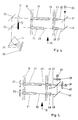
- Fig. 2 zeigt den Gesamtaufbau eines fotometrischen Analysengerätes,
- Fig. 3 zeigt den Verlauf der Strahlungsintensität in Abhängigkeit von der Zeit,
- Fig. 4 und Fig. 5 zeigen Fotometer gemäß der Erfindung, bei denen der Lichtstrahl vor dem Eintreten in das Medium in zwei Teilstrahlen aufgeteilt ist,
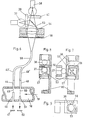
- Fig. 6 zeigt den Gesamtaufbau eines mit zwei Lichtquellen verschiedener Wellenlängen ausgestatteten Fotometers.
- Fig. 7 zeigt die Lichtquelleneinheit des Fotometers nach Fig. 6.
- Fig. 8 zeigt die Lichtquelleneinheit von der Seite.
- Fig. 9 zeigt den Grundriß dieser Einheit,
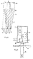
- Fig. 10 stellt den in ein Medium einzusetzenden Teil eines Fotometers dar,
- Fig. 11 stellt im Prinzip den Gesamtaufbau des Fotometers nach Fig. 10 dar.
- 1 shows schematically overlapping absorption lines of three components of a medium,
- 2 shows the overall structure of a photometric analyzer,
- 3 shows the course of the radiation intensity as a function of time,
- 4 and 5 show photometers according to the invention, in which the light beam is divided into two partial beams before entering the medium,
- 6 shows the overall structure of a photometer equipped with two light sources of different wavelengths.
- FIG. 7 shows the light source unit of the photometer according to FIG. 6.
- Fig. 8 shows the light source unit from the side.
- 9 shows the outline of this unit,
- 10 shows the part of a photometer to be inserted into a medium,
- Fig. 11 shows in principle the overall structure of the photometer according to Fig. 10.
In Figur 1 sind über der Wellenlänge λ die Absorptionsspektren der drei Komponenten S1, S2 und Ss eines Gemisches gezeichnet. An den ausgesuchten Wellenlängen λ1, λ2 und λ3 haben die Absorptionskurven ihre Maxima. Für die Extinktion En bei einer beliebigen Wellenlänge λn gilt die allgemeine Beziehung:![]()
- I : Länge der Absorptionsstrecke,
- En1...Enk : Absorptionskoeffizienten der Komponenten S1...Sk bei der Wellenlänge λn (vorgegeben),
- CI...Ck : Konzentrationen der Komponenten S1...Sk. Dabei ist n k.
Enthält wie im gewählten Beispiel das Gemisch drei Komponenten; so besteht der Klammerausdruck in
- I: length of the absorption section,
- E n1 ... E nk : absorption coefficients of the components S 1 ... S k at the wavelength λ n (given),
- CI ... Ck: concentrations of components S 1 ... S k . Where n k.
As in the selected example, the mixture contains three components; so the expression in brackets in
Die Extinktion ist mit der Strahlungsintensität durch die Gleichung 2 verknüpft:
- In : Intensität nach Durchlaufen der
Strecke 1, - oln : Intensität vor Durchlaufen der
Strecke 1.
Fig. 2 zeigt schematisch den Gesamtaufbau eines nach dem Wellenlängen-Vergleichsverfahren arbeitenden Fotometers, dessen Wirkungsweise nachstehend erläutert wird.The extinction is linked to the radiation intensity by equation 2:
- I n: intensity after crossing
route 1, - o l n : intensity before crossing
route 1.
Fig. 2 shows schematically the overall structure of a photometer operating according to the wavelength comparison method, the mode of operation of which is explained below.
Das Fotometer arbeitet nach dem Autokollimationsverfahren. Die von der breitbandigen Strahlungsquelle 1 ausgehenden Strahlen werden durch die Kollimatorlinse 2 gebündelt und gelangen über den Strahlteiler 3 in die Strahlleitvorrichtung 4 und von da über die Absorptionsstrecke 5 zu dem Reflektor 6. Die Reflexionsstrecke 5 befindet sich direkt im zu analysierenden Medium, das die Rohrleitung 7 durchströmt. Die Länge der Absorptionsstrecke 5 ist durch den Abstand des Reflektors 6 vom reflektorseitigen Ende der Strahlleitvorrichtung 4 bestimmt.The photometer works according to the autocollimation process. The rays emanating from the
Der Reflektor 6 wirft die Strahlen durch die Strahlleitvorrichtung 4 zurück zum Strahlteiler 3, der die Strahlen abbiegt und durch einen Spalt 8 auf das Prisma 9 lenkt. Die polychromatischen Strahlen werden dispergiert. Das dispergierte Licht wird auf einen Detektor 10 abgebildet, der aus einzelnen Fotoempfängem besteht, die im interessierenden Spektralbereich empfindlich sind. Jeder Fotoempfänger sendet ein der jeweiligen Wellenlänge zugeordnetes Signal in die Signalverarbeitungseinrichtung 11, die mit der Steuerelektronik 12 verbunden ist. An die Signalverarbeitungseinrichtung 11 ist außerdem das Anzeigegerät 13 angeschlossen.The
Sind in dem Detektor 10 n einzelne Fotoempfänger angeordnet, so werden n Empfängersignale In an die Signalverknüpfungseinheit 11 weitergegeben, in der durch eine Verknüpfung dieser Signale z. B. nach Regeln der Determinanten- bzw. Matrizen-Rechnung die gewünschten Konzentrationswerte C1 ...Ck ermittelt werden. Besteht das Medium beispielsweise aus drei Komponenten und werden die Signale dreier Fotoempfänger weiterverarbeitet, so ist für n und k jeweils 3 zu setzen. Für C1 beispielsweise erhält man dann:
- I = Länge der Absorptionsstrecke
- D = Konstante


dem teildurchlässigen Spiegel 3 in den Strahlengang eingeschwenkt wird. Auf diese Art sind jedoch Verschmutzungen der Absorptionsstrecke 5 durch Verunreinigungen im zu analysierenden Medium nicht kompensierbar. Dieser Nachteil wird dadurch beseitigt, daß der Reflektor 6 inder Rohrleitung 7 so angeordnet wird, daß er in Richtung der Lichtstrahlen bewegbar ist. Der Reflektor wird mittels einer Verschiebeeinrichtung 12 inRichtung des Doppelpfeiles 17 von einer definierten Stellung, diedurch 12 gekennzeichnet ist, in die Stellung Li gebracht und umgekehrt, in einem Zyklus, der vorher festgelegt wird. Auf diese Weise erhält die Absorptionsstrecke zwei Längen.Die größere Länge 12 ist die Meßstrecke und die kleinere Länge I1 die Referenzstrecke. DieVerschiebung der Verstelleinrichtung 16 erfolgt mit Hilfe derSpindel 15, die durch den andie Steuereinrichtung 12 angeschlossenen Schrittmotor 14 angetrieben wird.
- I = length of the absorption section
- D = constant
beam guiding device 4 and the partiallytransparent mirror 3 in a manner similar to that described in DE-AS-2 521 934. In this way, however, contamination of theabsorption section 5 due to contamination in the medium to be analyzed cannot be compensated. This disadvantage is eliminated in that thereflector 6 is arranged in thepipeline 7 so that it can be moved in the direction of the light beams. The reflector is moved by means of adisplacement device 12 in the direction of thedouble arrow 17 from a defined position, which is identified by 1 2 , to the position L i and vice versa, in a cycle which is determined beforehand. In this way, the absorption section is given two lengths. Thelarger length 1 2 is the measuring section and the smaller length I 1 is the reference section. Theadjustment device 16 is displaced with the aid of thespindle 15, which is driven by thestepper motor 14 connected to thecontrol device 12.
Fig. 3 zeigt, wie die bei den zwei Längen aufgenommenen Intensitäten periodisch zwischen zwei Werten hin und her pendeln. Die Intensität für die Referenzstrecke I1 ist mit I1ln, die Intensität für die Meßstrecke 12 mit I2ln bezeichnet.3 shows how the intensities recorded at the two lengths periodically oscillate between two values. The intensity for the reference path I 1 is denoted by I1 l n , the intensity for the measuring
Infolge der Ausgestaltung des Fotometers mit einem beweglichen Reflektor 6 ist in der Gleichung 3 die Länge I durch (12 - I1), In durch l2ln, und oln durch I1ln zu ersetzen. Es ergibt sich somit die der Signalverarbeitungseinheit 11 vorzugebende Gleichung: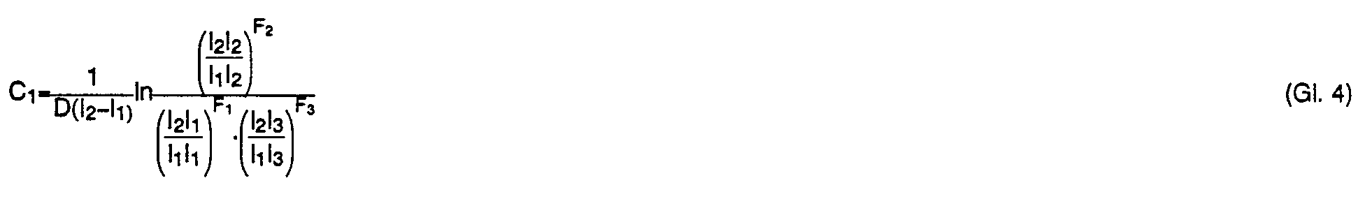

Der Teil des Uchtes, der den Spiegel 21 durchdringt, fällt auf den geneigten Spiegel 26, der das gesamte auf ihn treffende Licht als Teilstrahl 27 durch die Lichtleitvorrichtung 28 in den Behälter 18 sendet. Der Teilstrahl 27 durchläuft in dem Medium die Strecke 29 und verläßt den Behälter 18 durch die Lichtleitvorrichtung 30. Zur Erzielung der gewünschten Wirkung ist die Durchlaufstrecke 29 wesentlich länger als die Durchlaufstrecke 25.The part of the light that penetrates the
In dem Weg der Teilstrahlen 22 und 27 ist ein Blendenrad 31 angeordnet, das die Teilstrecken periodisch gegenphasig unterbricht.A
Hinter dem Blendenrad 31 sind die schrägstehenden Spiegel 32 und 33 vorgesehen, die die Teilstrahlen 22 und 27 in Richtung des Prismas 34 um lenken. Das dispergierende Licht 35 des Prismas 34 wird von einer Detektorzeile 36 aufgenommen, deren einzelne Fotoempfänger im interessierenden Spektralbereich empfindlich sind. Die Signalverarbeitung erfolgt in gleicher Weise wie an Hand des Fotometers nach Fig. 2 beschrieben.Behind the
Das zur Analyse eines Mehr-Komponenten-Mediums zu verwendende Fotometer nach Fig. 5 ist mit zwei Glühlampen 37 und 38 ausgestattet. Zur Erzeugung von Lichtstrahlen unterschiedlicher Frequenzen sind vor den Glühlampen 37 und 38 Interferenzfilter 39 und 40 vorgesehen. Die Glühlampen 37 und 38 werden durch einen elektronischen Geber so gesteuert, daß sie abwechselnd Lichtstrahlen auf den teildurchlässigen Spiegel 41 und den reflektierenden Spiegel 42 senden. Das vom Spiegel 41 reflektierte Licht tritt als Teilstrahl 43 durch die Lichtleitvorrichtung 44 in den Behälter 18 ein, den das Medium, z. B. ein Gas, in Richtung des Pfeiles 19 durchströmt. Dieser Teilstrahl 43 durchläuft das Medium auf der Strecke 45, tritt in die Lichtleitvorrichtung 46 ein, durch die er den Behälter 18 verläßt und trifft auf den fotoelektrischen Empfänger 47, der in dem Spektralbereich beider von den Interferenzfiltern 39 und 40 durchgelassenen Lichtstrahlen sensitiv ist.The photometer to be used for analyzing a multi-component medium according to FIG. 5 is equipped with two
Der Teil der den telldurchlässigen Spiegel 41 durchlaufenden Lichtstrahlen wird durch den geneigten Spiegel 42 durch die Lichtleitvorrichtung 48 in den Behälter 18 als Teilstrahl 49 reflektiert. Der Teilstrahl 49 durchläuft in dem zu analysierenden Medium die Strecke 50, verläßt den Behälter 18 durch die Lichtleitvorrichtung 51 und trifft auf den fotoelektrischen Empfänger 52, der wie der fotoelektrische Empfänger 47 in dem Spektralbereich beider von den Interferenzfiltem 39 und 40 durchgelassenen Lichtstrahlen empfindlich ist.The part of the light rays passing through the tell-
Den fotoelektrischen Empfängern 47 und 52 ist ein nicht dargestellter elektronischer Schalter zugeordnet. dem zwei elektronische Verarbeitungsstufen, insbesondere zwei logarithmisch arbeitende Differenzverstärker nachgeordnet sind. Der elektronische Schalter ist mit dem elektronischen Geber für die Lampen 37 und 38 synchronisiert. Der elektronische Schalter führt jeweils die Signale der bei den fotoelektrischen Empfänger 47 und 52 gegenphasig einem dieser elektronischen Verarbeitungsstufen zu.An electronic switch (not shown) is assigned to the
Das anhand der Fig. 5 erläuterte Fotometer kann insbesondere zur Analyse eines Mediums benutzt werden, das aus zwei Komponenten besteht.The photometer explained with reference to FIG. 5 can be used in particular for the analysis of a medium which consists of two components.
Bei dem Fotometer gemäß den Figuren 6 bis 9 sind als Lichtquellen zwei Glühlampen 37 und 38 vorgesehen. Das Licht der Glühlampe 37 wird durch das Interferenzfifter 39 und den teildurchlässigen Spiegel 53 auf die Kollimatorlinse 54 geleitet. Das Licht der Glühlampe 38 wird durch das Interferenzfilter 40 und den Spiegel 53 ebenfalls auf die Kollimatodinse 54 geleitet. Das Interferenzfilter 39 ist in der Tasche 55 angeordnet; das Interferenzfifter 40 ist in der Tasche 56 angeordnet. Die Glühlampen 37 und 38 sind in einem rechten Winkel zueinander angeordnet. Die Kollimatorlinse wird in der Fassung 57 aufgenommen. Zur Änderung des öffnungswinkels ist eine in ihrer Weite verstellbare Blende 58 vorgesehen.In the photometer according to FIGS. 6 to 9, two
Das von der Linse 54 gebündelte Licht wird, wie aus Fig. 6 ersichtlich, von dem Lichtfaserbündel 59 aufgenommen. Die Ankopplung des Lichtfaserbündels erfolgt durch die Buchse 60. Das Lichtfaserbündel 59 gabelt sich in die Arme 43' und 49'. Der Teillichtstrahl des Armes 43' wird durch den Lichtleitstab 44 in den vom zu analysierenden Medium durchströmten Behälter 18 geleitet; der Teillichtstrahl des Armes 49' wird durch den Lichtleitstab 48 dem Behälter 18 zugeführt. In dem Behälter 18 sind die lichtautnehmenden Lichtleiter 46 und 51 so angeordnet, daß der von dem Lichtleitstab 44 zugeführte Teillichtstrahl eine Absorptionsstrecke 45 durchläuft, die kleiner ist als die Absorptionsstrecke 50 des Teillichtstrahles durch den Lichtleitstab 48.As can be seen in FIG. 6, the light bundled by the
Die Interferenzfilter 39 und 40 bewirken, daß das von der Glühlampe 37 stammende Licht sich in seiner Wellenlänge von dem Licht der Glühlampe 38 unterscheidet. Alternierend wird Licht der einen oder anderen Wellenlänge gleichzeitig über die Absorptionsstrecken 45 und 50 geführt. Zum Ein- und Ausschalten der Glühlampen 37 und 38 in dem gewünschten Rhythmus ist ein Schalter, insbesondere ein elektronischer Schalter, vorgesehen.The interference filters 39 and 40 cause the light coming from the
Der Teilstrahl, der längs der Absorptionsstrecke 45 das Medium, das den Behälter 18 in Richtung des Pfeiles 19 durchströmt, durchlaufen hat, wird von dem fotoelektrischen Empfänger 47 aufgenommen; der Teilstrahl längs der längeren Absorptionsstrecke 50 wird von dem fotoelektrischen Empfänger 52 aufgenommen. Den fotoelektrischen Empfängern 47 und 52 ist ein Schalter, insbesondere elektronischer Art, zugeordnet, der synchron zu dem die Glühlampen 37 und 38 schaltenden Schalter arbeitet. Durch diesen Schalter werden jeweils die Signale bei der fotoelektrischen Empfänger 47 und 52 gegenphasig einer von zwei nachgeordneten elektronischen Verarbeitungsstufen zugeführt.The partial beam which has passed through the medium along the
Die Glühlampen 37 und 38, die Interferenzfilter 39 und 40 bilden zusammen mit dem teildurchlässigen Spiegel 53 der Kollimatorlinse 54 und der Blende 58 eine Baueinheit, deren prinzipieller Aufbau in den Figuren 7,8 und 9 dargestellt ist.The
Fig. 10 zeigt den in das zu analysierende Medium einzusetzenden Teil des Fotometers. Er besteht aus dem Lichtleiter 61, der das Eingangslicht direkt an ein Prisma 62 weitergibt. Das an das Prisma 62 weitergegebene Licht pflanzt sich im Prisma in Form des Kegelstumpfes 63 fort (enge Schraffur); es verläßt das Prisma in Form des Kegels 64 (weite Schraffur). Ein Teil des reflektierten Lichtes wird nach Durchlaufen einer kurzen Absorptionsstrecke 65 von dem Lichtleiter 66 (erster Teilstrahl) aufgenommen. Ein weiterer Teil des reflektierten Lichtes wird nach Durchlaufen der längeren Absorptionsstrecke 67 von dem Lichtleiter 68 aufgenommen (zweiter Teilstrahl). Die Längen der Absorptionsstrecken sind variabel; sie werden den jeweiligen Meßaufgaben angepaßt.10 shows the part of the photometer to be inserted into the medium to be analyzed. It consists of the
Eine hohe Meßempfindlichkeit wird dadurch erreicht, daß der Durchmesser des Lichtleiters 68 größer gewählt wird als der Durchmesser des Lichtleiters 66.A high measuring sensitivity is achieved in that the diameter of the
Die in Fig. 10 dargestellte Einheit 69 stellt einen Sensor dar, der zur in-line Messung geeignet ist. Sie läßt sich wie Fig. 11 erkennen läßt, baulich mit einem Gehäuse 70 zusammensetzen, in dem eine Strahlungsquelle 71 angeordnet ist sowie eine Empfangseinrichtung 72 für die Signale, die durch die Lichtleiter 66 und 68 zugeführt werden. Mit Hilfe des Flansches 73 wird das Fotometer an den von einem zu analysierenden Medium durchströmten Behälter angeschlossen. Als Strahlungsquelle 71 kann eine Anordnung gewählt werden, wie in Fig. 6 dargestellt.The
Als Lichtleiter 61, 66 und 68 können starre Lichtleitstäbe verwendet werden. Ebenso lassen sich die Lichtleiter 61, 66 und 68 aus Faserbündeln herstellen. Es ist auch möglich, den unteren Teil der Lichtleiter starr auszubilden und den oberen Teil als Faserbündel.Rigid light guide rods can be used as light guides 61, 66 and 68. The light guides 61, 66 and 68 can also be produced from fiber bundles. It is also possible to make the lower part of the light guide rigid and the upper part as a fiber bundle.
Zur Kalibrierung des Fotometers wird eine Küvette in den zweiten Teilstrahl, d. h. in den Teilstrahl, der die längere Absorptionsstrecke durch läuft, geschoben. Die Empfangseinrichtung 72 läßt sich so ausbilden, daß sie diese Kalibrierküvette aufnehmen kann. Die Empfangseinrichtung kann mit einen Temperatur-Korrekturglied ausgestattet sein, das dem Umstand Rechnung trägt, daß das Fotometer in Medien unterschiedlicher Temperatur eingesetzt wird.To calibrate the photometer, a cuvette is placed in the second partial beam, i.e. H. pushed into the partial beam that runs through the longer absorption section. The receiving
Claims (10)
Applications Claiming Priority (8)
| Application Number | Priority Date | Filing Date | Title |
|---|---|---|---|
| DE19833339950 DE3339950A1 (en) | 1983-11-04 | 1983-11-04 | Photometer for continuously analysing a medium (gas or liquid) |
| DE3339950 | 1983-11-04 | ||
| DE19843422309 DE3422309A1 (en) | 1983-11-04 | 1984-06-15 | Photometer for continuous analysis of a medium |
| DE3422309 | 1984-06-15 | ||
| DE19843423471 DE3423471A1 (en) | 1984-06-15 | 1984-06-26 | Photometer for continuous analysis of a medium (gas or liquid) consisting of a plurality of components |
| DE3423471 | 1984-06-26 | ||
| DE3423922 | 1984-06-29 | ||
| DE19843423922 DE3423922A1 (en) | 1984-06-29 | 1984-06-29 | Photometer for continuously analysing a plurality of components of a liquid or gaseous medium |
Publications (3)
| Publication Number | Publication Date |
|---|---|
| EP0145877A2 EP0145877A2 (en) | 1985-06-26 |
| EP0145877A3 EP0145877A3 (en) | 1986-01-08 |
| EP0145877B1 true EP0145877B1 (en) | 1989-08-02 |
Family
ID=27433016
Family Applications (1)
| Application Number | Title | Priority Date | Filing Date |
|---|---|---|---|
| EP84112134A Expired EP0145877B1 (en) | 1983-11-04 | 1984-10-10 | Photometer for continuous analysis of a medium (gas or liquid) |
Country Status (2)
| Country | Link |
|---|---|
| EP (1) | EP0145877B1 (en) |
| DE (1) | DE3479241D1 (en) |
Families Citing this family (20)
| Publication number | Priority date | Publication date | Assignee | Title |
|---|---|---|---|---|
| US4616134A (en) * | 1984-07-17 | 1986-10-07 | Chevron Research Company | High resolution geologic sample scanning apparatus and process of scanning geologic samples |
| DE3625490A1 (en) * | 1986-07-28 | 1988-02-04 | Kernforschungsz Karlsruhe | MULTI-COMPONENT PROCESS ANALYSIS SYSTEM |
| US4786171A (en) * | 1986-07-29 | 1988-11-22 | Guided Wave, Inc. | Spectral analysis apparatus and method |
| DE3938142A1 (en) * | 1989-11-16 | 1991-05-29 | Mak Maschinenbau Krupp | METHOD AND DEVICE FOR QUALITATIVE AND QUANTITATIVE DETERMINATION OF INGREDIENTS |
| US5125747A (en) * | 1990-10-12 | 1992-06-30 | Tytronics, Inc. | Optical analytical instrument and method having improved calibration |
| GB9100502D0 (en) * | 1991-01-10 | 1991-02-20 | Ici Plc | Monitoring device |
| JP2520212B2 (en) * | 1992-09-07 | 1996-07-31 | 倉敷紡績株式会社 | Concentration measuring device |
| SE9403543D0 (en) * | 1994-10-18 | 1994-10-18 | Arums Ltd | Method and probe for on-line optical analysis |
| US5770156A (en) * | 1996-06-04 | 1998-06-23 | In Usa, Inc. | Gas detection and measurement system |
| US5859430A (en) * | 1997-04-10 | 1999-01-12 | Schlumberger Technology Corporation | Method and apparatus for the downhole compositional analysis of formation gases |
| FR2763129B1 (en) * | 1997-05-06 | 1999-07-02 | Bertin & Cie | OPTICAL FIBER DEVICE FOR AUTOMATIC DETECTION OF FOREIGN SUBSTANCES IN A LIQUID |
| GB2342610B (en) | 1998-10-14 | 2003-01-15 | Heckett Multiserv Plc | Surface treatment of metal articles |
| US6342948B1 (en) * | 1998-11-20 | 2002-01-29 | Waters Investments Limited | Dual pathlength system for light absorbance detection |
| DE10351160B3 (en) * | 2003-11-03 | 2005-03-31 | Roche Diagnostics Gmbh | Continuous-flow cuvette and mid-range infra-red transmission spectrometer for biological fluids, comprises flow channel with two separate optical paths |
| EP1880193A1 (en) | 2004-12-02 | 2008-01-23 | FOSS Analytical A/S | Spectrophotometer |
| DE102006004916B3 (en) * | 2006-02-01 | 2007-06-14 | GEA Process Engineering (NPS) Ltd., Eastleigh | Material e.g. fluid, concentration measuring device e.g. immersion sensor, has adjusting device to adjust distance between deflecting unit and transmitter and/or receiver such that unit forms space with housing in one position of unit |
| DE102007058611A1 (en) * | 2007-12-04 | 2009-06-10 | Endress + Hauser Conducta Gesellschaft für Mess- und Regeltechnik mbH + Co. KG | ATR probe |
| DE102008064173B4 (en) * | 2008-12-22 | 2011-06-01 | Universität Rostock | Method and device for determining the substance concentration in gaseous or fluid media by means of optical absorption spectroscopy with broadband light sources |
| DE102013101523A1 (en) * | 2013-02-15 | 2014-08-21 | B. Braun Avitum Ag | A photometric measuring apparatus and method for measuring an optical absorbance of a fluid having a variable concentration of at least one light-absorbing substance, and a blood processing apparatus having such a measuring apparatus |
| DE102016008826B4 (en) * | 2016-07-19 | 2024-04-25 | Sartorius Stedim Biotech Gmbh | Spectroscopic measurement for containers |
Family Cites Families (3)
| Publication number | Priority date | Publication date | Assignee | Title |
|---|---|---|---|---|
| DE2521934C3 (en) * | 1975-05-16 | 1978-11-02 | Erwin Sick Gmbh Optik-Elektronik, 7808 Waldkirch | Device for determining the concentrations of components in an exhaust gas mixture |
| JPS56153242A (en) * | 1980-04-30 | 1981-11-27 | Fuji Electric Co Ltd | measuring device for organic pollution component contained in water |
| JPS5868645A (en) * | 1981-10-19 | 1983-04-23 | Mitsubishi Heavy Ind Ltd | Method for measuring concentration of particles |
-
1984
- 1984-10-10 EP EP84112134A patent/EP0145877B1/en not_active Expired
- 1984-10-10 DE DE8484112134T patent/DE3479241D1/en not_active Expired
Also Published As
| Publication number | Publication date |
|---|---|
| EP0145877A2 (en) | 1985-06-26 |
| DE3479241D1 (en) | 1989-09-07 |
| EP0145877A3 (en) | 1986-01-08 |
Similar Documents
| Publication | Publication Date | Title |
|---|---|---|
| EP0145877B1 (en) | Photometer for continuous analysis of a medium (gas or liquid) | |
| DE2415049C3 (en) | Spectrophotometer for measuring the absorbency of chromatographically separated liquids | |
| EP0476088B1 (en) | Acousto-optic tunable double-beam spectrometer | |
| DE2364069C3 (en) | Spectrophotometer | |
| EP0163847B1 (en) | Interferential refractometer | |
| DE19713928C1 (en) | IR absorption measuring device for gas concentration measurement | |
| DE60133002T2 (en) | SPECTROPHOTOMETER WITH SEVERAL WAY LENGTHS | |
| DE102009025147B3 (en) | Method for operating a spectrometer for gas analysis, and spectrometer itself | |
| DE2637246B2 (en) | Method and device for the inspection of glass containers | |
| DE3724852C2 (en) | Absorption photometer | |
| EP3077793B1 (en) | Analysis device (photometer) having a serial light guide | |
| DE2420060A1 (en) | SPECTRAL PHOTOMETRIC PROCEDURE AND REUSABLE SPECTRAL PHOTOMETERS FOR THE IMPLEMENTATION OF THE SAME | |
| DE2651086C3 (en) | ||
| DE3938142C2 (en) | ||
| DE2948590C2 (en) | Device for measuring the absorption of gas mixtures | |
| EP1064543B1 (en) | Thin-layer chromatography apparatus | |
| EP0087077A2 (en) | Measuring device for optical gas analysis | |
| DE1472144A1 (en) | Spectrophotometer | |
| DE3339950A1 (en) | Photometer for continuously analysing a medium (gas or liquid) | |
| EP0043522B1 (en) | Refractometer | |
| DE3630292C1 (en) | Scattered light photometer | |
| DE19543729B4 (en) | spectrometer | |
| DE102006018287B4 (en) | Apparatus and method for the spectral analytical evaluation of materials or objects in a material or object stream | |
| DE3625239C2 (en) | ||
| DE2032195C3 (en) | Multi-channel colorimeters, especially flow-through colorimeters |
Legal Events
| Date | Code | Title | Description |
|---|---|---|---|
| PUAI | Public reference made under article 153(3) epc to a published international application that has entered the european phase |
Free format text: ORIGINAL CODE: 0009012 |
|
| AK | Designated contracting states |
Designated state(s): CH DE FR GB LI NL |
|
| RTI1 | Title (correction) | ||
| PUAL | Search report despatched |
Free format text: ORIGINAL CODE: 0009013 |
|
| AK | Designated contracting states |
Designated state(s): CH DE FR GB LI NL |
|
| 17P | Request for examination filed |
Effective date: 19860514 |
|
| 17Q | First examination report despatched |
Effective date: 19870817 |
|
| GRAA | (expected) grant |
Free format text: ORIGINAL CODE: 0009210 |
|
| AK | Designated contracting states |
Kind code of ref document: B1 Designated state(s): CH DE FR GB LI NL |
|
| REF | Corresponds to: |
Ref document number: 3479241 Country of ref document: DE Date of ref document: 19890907 |
|
| ET | Fr: translation filed | ||
| ET1 | Fr: translation filed ** revision of the translation of the patent or the claims | ||
| GBT | Gb: translation of ep patent filed (gb section 77(6)(a)/1977) | ||
| R20 | Corrections of a patent specification |
Effective date: 19890904 |
|
| ET1 | Fr: translation filed ** revision of the translation of the patent or the claims | ||
| PLBE | No opposition filed within time limit |
Free format text: ORIGINAL CODE: 0009261 |
|
| STAA | Information on the status of an ep patent application or granted ep patent |
Free format text: STATUS: NO OPPOSITION FILED WITHIN TIME LIMIT |
|
| 26N | No opposition filed | ||
| PGFP | Annual fee paid to national office [announced via postgrant information from national office to epo] |
Ref country code: DE Payment date: 19910910 Year of fee payment: 8 |
|
| PGFP | Annual fee paid to national office [announced via postgrant information from national office to epo] |
Ref country code: CH Payment date: 19910912 Year of fee payment: 8 |
|
| PGFP | Annual fee paid to national office [announced via postgrant information from national office to epo] |
Ref country code: GB Payment date: 19911002 Year of fee payment: 8 |
|
| PGFP | Annual fee paid to national office [announced via postgrant information from national office to epo] |
Ref country code: FR Payment date: 19911030 Year of fee payment: 8 |
|
| PGFP | Annual fee paid to national office [announced via postgrant information from national office to epo] |
Ref country code: NL Payment date: 19911031 Year of fee payment: 8 |
|
| PG25 | Lapsed in a contracting state [announced via postgrant information from national office to epo] |
Ref country code: GB Effective date: 19921010 |
|
| PG25 | Lapsed in a contracting state [announced via postgrant information from national office to epo] |
Ref country code: LI Effective date: 19921031 Ref country code: CH Effective date: 19921031 |
|
| PG25 | Lapsed in a contracting state [announced via postgrant information from national office to epo] |
Ref country code: NL Effective date: 19930501 |
|
| GBPC | Gb: european patent ceased through non-payment of renewal fee |
Effective date: 19921010 |
|
| NLV4 | Nl: lapsed or anulled due to non-payment of the annual fee | ||
| PG25 | Lapsed in a contracting state [announced via postgrant information from national office to epo] |
Ref country code: FR Effective date: 19930630 |
|
| REG | Reference to a national code |
Ref country code: CH Ref legal event code: PL |
|
| PG25 | Lapsed in a contracting state [announced via postgrant information from national office to epo] |
Ref country code: DE Effective date: 19930701 |
|
| REG | Reference to a national code |
Ref country code: FR Ref legal event code: ST |