EP0145770B1 - Laser surgery - Google Patents
Laser surgery Download PDFInfo
- Publication number
- EP0145770B1 EP0145770B1 EP84902487A EP84902487A EP0145770B1 EP 0145770 B1 EP0145770 B1 EP 0145770B1 EP 84902487 A EP84902487 A EP 84902487A EP 84902487 A EP84902487 A EP 84902487A EP 0145770 B1 EP0145770 B1 EP 0145770B1
- Authority
- EP
- European Patent Office
- Prior art keywords
- laser
- optical path
- common optical
- energy
- patient
- Prior art date
- Legal status (The legal status is an assumption and is not a legal conclusion. Google has not performed a legal analysis and makes no representation as to the accuracy of the status listed.)
- Expired - Lifetime
Links
- 238000002430 laser surgery Methods 0.000 title claims abstract description 18
- 230000003287 optical effect Effects 0.000 claims abstract description 63
- XKRFYHLGVUSROY-UHFFFAOYSA-N Argon Chemical compound [Ar] XKRFYHLGVUSROY-UHFFFAOYSA-N 0.000 claims abstract description 6
- 229910052786 argon Inorganic materials 0.000 claims abstract description 3
- 230000008878 coupling Effects 0.000 claims description 6
- 238000010168 coupling process Methods 0.000 claims description 6
- 238000005859 coupling reaction Methods 0.000 claims description 6
- 239000000725 suspension Substances 0.000 claims description 2
- 238000006073 displacement reaction Methods 0.000 claims 1
- CPBQJMYROZQQJC-UHFFFAOYSA-N helium neon Chemical compound [He].[Ne] CPBQJMYROZQQJC-UHFFFAOYSA-N 0.000 claims 1
- 238000013532 laser treatment Methods 0.000 claims 1
- CURLTUGMZLYLDI-UHFFFAOYSA-N Carbon dioxide Chemical compound O=C=O CURLTUGMZLYLDI-UHFFFAOYSA-N 0.000 abstract description 8
- 229910002092 carbon dioxide Inorganic materials 0.000 abstract description 7
- 229910052779 Neodymium Inorganic materials 0.000 abstract description 5
- QEFYFXOXNSNQGX-UHFFFAOYSA-N neodymium atom Chemical compound [Nd] QEFYFXOXNSNQGX-UHFFFAOYSA-N 0.000 abstract description 5
- 239000001569 carbon dioxide Substances 0.000 abstract description 4
- 238000001816 cooling Methods 0.000 abstract description 4
- 238000001356 surgical procedure Methods 0.000 abstract description 4
- 230000015271 coagulation Effects 0.000 abstract description 2
- 238000005345 coagulation Methods 0.000 abstract description 2
- 238000000034 method Methods 0.000 description 5
- 230000001112 coagulating effect Effects 0.000 description 2
- 230000000694 effects Effects 0.000 description 2
- 230000035939 shock Effects 0.000 description 2
- XLYOFNOQVPJJNP-UHFFFAOYSA-N water Substances O XLYOFNOQVPJJNP-UHFFFAOYSA-N 0.000 description 2
- 239000006096 absorbing agent Substances 0.000 description 1
- 238000002591 computed tomography Methods 0.000 description 1
- 238000001704 evaporation Methods 0.000 description 1
- 230000008020 evaporation Effects 0.000 description 1
- 208000014674 injury Diseases 0.000 description 1
- 230000001678 irradiating effect Effects 0.000 description 1
- 230000001681 protective effect Effects 0.000 description 1
- 230000008733 trauma Effects 0.000 description 1
Images

Classifications
-
- A—HUMAN NECESSITIES
- A61—MEDICAL OR VETERINARY SCIENCE; HYGIENE
- A61B—DIAGNOSIS; SURGERY; IDENTIFICATION
- A61B18/00—Surgical instruments, devices or methods for transferring non-mechanical forms of energy to or from the body
- A61B18/18—Surgical instruments, devices or methods for transferring non-mechanical forms of energy to or from the body by applying electromagnetic radiation, e.g. microwaves
- A61B18/20—Surgical instruments, devices or methods for transferring non-mechanical forms of energy to or from the body by applying electromagnetic radiation, e.g. microwaves using laser
-
- A—HUMAN NECESSITIES
- A61—MEDICAL OR VETERINARY SCIENCE; HYGIENE
- A61B—DIAGNOSIS; SURGERY; IDENTIFICATION
- A61B17/00—Surgical instruments, devices or methods, e.g. tourniquets
- A61B2017/00973—Surgical instruments, devices or methods, e.g. tourniquets pedal-operated
-
- A—HUMAN NECESSITIES
- A61—MEDICAL OR VETERINARY SCIENCE; HYGIENE
- A61B—DIAGNOSIS; SURGERY; IDENTIFICATION
- A61B18/00—Surgical instruments, devices or methods for transferring non-mechanical forms of energy to or from the body
- A61B2018/00636—Sensing and controlling the application of energy
-
- A—HUMAN NECESSITIES
- A61—MEDICAL OR VETERINARY SCIENCE; HYGIENE
- A61B—DIAGNOSIS; SURGERY; IDENTIFICATION
- A61B18/00—Surgical instruments, devices or methods for transferring non-mechanical forms of energy to or from the body
- A61B18/18—Surgical instruments, devices or methods for transferring non-mechanical forms of energy to or from the body by applying electromagnetic radiation, e.g. microwaves
- A61B18/20—Surgical instruments, devices or methods for transferring non-mechanical forms of energy to or from the body by applying electromagnetic radiation, e.g. microwaves using laser
- A61B2018/2015—Miscellaneous features
- A61B2018/2025—Miscellaneous features with a pilot laser
-
- A—HUMAN NECESSITIES
- A61—MEDICAL OR VETERINARY SCIENCE; HYGIENE
- A61B—DIAGNOSIS; SURGERY; IDENTIFICATION
- A61B18/00—Surgical instruments, devices or methods for transferring non-mechanical forms of energy to or from the body
- A61B18/18—Surgical instruments, devices or methods for transferring non-mechanical forms of energy to or from the body by applying electromagnetic radiation, e.g. microwaves
- A61B18/20—Surgical instruments, devices or methods for transferring non-mechanical forms of energy to or from the body by applying electromagnetic radiation, e.g. microwaves using laser
- A61B2018/2035—Beam shaping or redirecting; Optical components therefor
- A61B2018/20351—Scanning mechanisms
- A61B2018/20359—Scanning mechanisms by movable mirrors, e.g. galvanometric
-
- A—HUMAN NECESSITIES
- A61—MEDICAL OR VETERINARY SCIENCE; HYGIENE
- A61B—DIAGNOSIS; SURGERY; IDENTIFICATION
- A61B18/00—Surgical instruments, devices or methods for transferring non-mechanical forms of energy to or from the body
- A61B18/18—Surgical instruments, devices or methods for transferring non-mechanical forms of energy to or from the body by applying electromagnetic radiation, e.g. microwaves
- A61B18/20—Surgical instruments, devices or methods for transferring non-mechanical forms of energy to or from the body by applying electromagnetic radiation, e.g. microwaves using laser
- A61B2018/2065—Multiwave; Wavelength mixing, e.g. using four or more wavelengths
- A61B2018/207—Multiwave; Wavelength mixing, e.g. using four or more wavelengths mixing two wavelengths
-
- A—HUMAN NECESSITIES
- A61—MEDICAL OR VETERINARY SCIENCE; HYGIENE
- A61B—DIAGNOSIS; SURGERY; IDENTIFICATION
- A61B34/00—Computer-aided surgery; Manipulators or robots specially adapted for use in surgery
- A61B34/70—Manipulators specially adapted for use in surgery
- A61B34/74—Manipulators with manual electric input means
- A61B2034/742—Joysticks
Definitions
- the present invention concerns novel apparatus and techniques for peforming a wide variety of surgical procedures in an operating room with precision and reduced trauma for patients while facilitating observation and recordation through the use of laser sources of different wavelengths transmittable to a patient over a common optical path that is also observable by the surgeon.
- DE-A-3242612 discloses laser irradiating apparatus which provides a plurality of laser sources which output laser beams of different wavelengths.
- the laser beams are overlapped and transmitted to a patient.
- the lasers are provided with variable controls for adjusting and mixing their respective outputs.
- US-A-4091814 discloses laser apparatus which has a microscope directed along a portion of an operating laser beam and which has a joystick for controlling the position of the incident laser beam.
- US-A-2809007 discloses laser surgery apparatus having two laser sources which are coupled to a common optical path by a half- silvered mirror.
- US-A-4069823 discloses thereby apparatus having one or more lasers and which is supported by an overhead suspension system.
- laser surgery apparatus comprising:
- the apparatus is suspended over the operating table from rails that facilitate X-Y movement in the horizontal plane, and the common optical path comprises a telescoping assembly that allows movement in the Z direction.
- the system may include vents, an aspirator and a fiberoptic lighting system for illuminating with sterile disposable plastic covers.
- one of the laser sources is a carbon dioxide laser for cutting and a second is a neodymium YAG laser for coagulation, or evaporation.
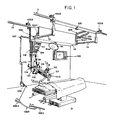
- FIG. 1 there is a shown a perspective view of a multipurpose, multiwavelength surgical laser system suspended from X rails 11 and 12 and Y rails 13 and 14.
- X rails 11 and 12 support Y rails 13 and 14 which support housing 15.
- Housing 15 includes the lasers with associated power supplies, controllers and cooling systems and supports accessory operating room light 16 and other elements in the system positionable in X, Y and Z as described below.
- a stationary column 118 depends from housing 15 and accommodates telescoping column 113 comprising a common optical path for transmitting energy from a laser source and allowing the surgeon to observe the incision.
- a motor may provide mechanical energy for lowering and raising the telescoping structure 113 as indicated by arrows A in accordance with well-known techniques, not described in detail herein to avoid obscuring the principles of the invention, when actuated by an appropriate control button on switch pad 112 to provide Z-axis positioning.
- a microscopic delivery system arm 110 selectively angularly displaced about its fixed end by motor 114, as indicated by arrows D-D, and manually rotatable about vertical and horizontal axes, as indicated by arrows B and C, is carried by and optically coupled to end section 121 and includes a microscope 115 with variable magnification.
- a switch pad 112 controls motor 114 to selectively raise and lower the delivery arm 110 with fine and coarse adjustment in accordance with well-known techniques. Switch pad 112 may be used to effect X-Y positioning of the apparatus by releasing brakes, such as 102, to allow manual movement.
- Electromechanical brake 102 which may be of conventional type, mechanically graps the rail 11 when deenergized, and a solenoid acts against a spring when the solenoid is energized to release the brake and allow movement, thereby normally keeping the assembly stationary for observation and/or cutting, and/or coagulating.
- the brakes for rails 13 and 14 are not visible in Fig. 1 and are in housing 15.
- a television camera 119 provides a television signal of what is observed through microscope 115 for display on television monitor 120 and may also deliver this signal to a hard copy printer or video recorder system for recording.
- Television camera 119 may also comprise a robotic eye when the invention is used in connection with an automatic control system to, for example, guide and control the cutting laser along a predetermined path.
- the invention may also include an articulated arm delivery system 107 terminating in a hand piece coupler assembly 108 which may be used by a surgeon in a manner analogous to a scalpel, while using laser energy not only for cutting, but also for coagulating.
- a hand piece may be coupled to system 107 by a short fiberoptics coupler. This coupling arrangement is shown magnified as optical input jack 108A, fiberoptic cable 108B and endoscope 108C.
- the apparatus is suspended above an operating table 21 above a patient 22 where it may be conveniently controlled by a surgeon having access to control panel 109, microscope 115, joystick 117 with a trigger switch on its end and/or a footswitch (not shown) and switch pad 112. Actuating the trigger switch or footswitch typically operates shutter A or B (Fig. 3) to allow laser energy from an associated laser to enter the common optical path as described below.
- Keyboard 116 on control panel 109 may be used to enter appropriate commands for CW and/or pulsed operation of the lasers or other information when the apparatus is used in connection with a computer.
- Meters 111 indicate appropriate power level operating information, or laser potentials and/or currents.
- An optical switch 106 allows manual direction of laser energy selectively into the telescoping assembly below or the articulated arm 107.
- Power cables 104 provide electrical power to the lasers and associated equipment in housing 15.
- Water hoses 105 provide water for cooling.
- Housing 15 may include an aiming laser with power supply 202, carbon dioxide laser 203, cooling package 205 and 207, carbon dioxide laser power supply 206, neodymium YAG laser 204, neodymium YAG laser power supply 208 and a conventional control unit 209, containing relays, interlocks, circuit breakers, controls for the operating modes of the lasers and the like.
- Optical port 201 admits laser beam energy to the telescope below.
- HeNe or Argon laser 202 illuminates a 45° reflector 302 that deflects the beam along the axis 31 of the telescoping section below through coated mirrors 304 and 305.
- Coated mirror 304 receives the laser beam from neodymium YAG laser 204 through focusing lens 301.
- Perforated mirror 305 receives the laser beam from C0 2 laser 203. With reflecting mirror 306 actuated by switch 106 (Fig.
- Turret 310 includes three lenses; one for C0 2 laser and aiming light, the second for Nd-YAG laser and aiming light, and the third a compromise for all wavelengths.
- the first two are interlocked so that only the associated laser acts on a patient when a respective lens is positioned along the common optical path.
- the surgeon may then observe through microscope 315 the effect of the laser on the patient while controlling its position with joystick 117.
- the perforation on axis of lens 316 passes the laser beam freely while the remaining portion acts as a collimating lens for viewing and recording.
- the microscope may also include an indicator for power output, lasers then being used and interlock indicator.
- Electromechanical shutters A and B intercept the outputs of Nd-YAG and C02 lasers 204 and 203 respectively with a 45° mirror to also function as a heat sink power meter element when positioned as shown in accordance with well-known techniques.
- the active laser beam is directed upon reflecting mirror 307 into articulated arm delivery system 107.
- X-Y controller 313 preferably includes stepping motors for positioning mirror 311.
- Optics 314 preferably includes an interlocked protective optic filter interposed when Nd-YAG laser 204 or other high power laser is being used.
- Television camera 119 preferably receives an optical image of the area of the patient being treated surgically through a 45° prism 317 and zoom lens 318 of a known type not described in detail to avoid obscuring the principles of the invention.
- the invention has a number of advantages. It provides a multipurpose multiwavelength laser system having the flexibility to deliver one or more beams under precise convenient practical control of the operating surgeon while being compatible with computer operation. It may be installed in a dedicated operating room that allows the surgeon to develop new procedures where in whole, or in part, the laser surgical system may be used to achieve more precision and less invasive surgery.
- the invention is also compatible with diagnostic instrumentation having computer storage in which stored diagnostic information may be processed for automatic or semiautomatic surgery. Then, suitable stepping motors or other drives may be included for controlling movement along directions B and C as well as A and D. For example, information of a CAT scan or NMR of the patient in computer storage may be processed and utilized to assist the surgeon in removing tissue more uniformly and speedily.
Abstract
Description
- The present invention concerns novel apparatus and techniques for peforming a wide variety of surgical procedures in an operating room with precision and reduced trauma for patients while facilitating observation and recordation through the use of laser sources of different wavelengths transmittable to a patient over a common optical path that is also observable by the surgeon.
- As an example of prior art laser surgical apparatus reference is made to US―A―3487835, US-A-3528424, US―A―3642007, US-A-3659613, US―A―3769963, US-A-3796220, US-A-3865113, US-A-3865114, US-A--3910276, US-A-4069823, US―A―4170997 and US―A―4174154.
- DE-A-3242612 discloses laser irradiating apparatus which provides a plurality of laser sources which output laser beams of different wavelengths. The laser beams are overlapped and transmitted to a patient. The lasers are provided with variable controls for adjusting and mixing their respective outputs.
- US-A-4091814 discloses laser apparatus which has a microscope directed along a portion of an operating laser beam and which has a joystick for controlling the position of the incident laser beam.
- US-A-2809007 discloses laser surgery apparatus having two laser sources which are coupled to a common optical path by a half- silvered mirror.
- US-A-4069823 discloses thereby apparatus having one or more lasers and which is supported by an overhead suspension system.
- It is an important object of this invention to
- provide an improved laser surgical apparatus. According to the present invention, laser surgery apparatus comprising:
- at least first and second laser sources of optical energy at different wavelengths;
- means defining a common optical path for exchanging optical energy with a patient;
- means for coupling the laser sources to the common optical path including at least one perforated mirror for allowing simultaneous delivery of energy from the laser sources over the common optical path to the patient; and
- means for simultaneously moving the laser beams together over a region at the patient end of the optical path;
- microscope means having its optical axis oriented along a portion of the common optical path and coupled to the means defining a common optical path for allowing a surgeon to observe through the microscope means the region of a patient upon which laser energy may act, the microscope means comprising perforated lens means formed with a small perforation embracing the common optical axis for passing a beam of laser energy therethrough while converging optical rays from said region of a patient.
- Preferably the apparatus is suspended over the operating table from rails that facilitate X-Y movement in the horizontal plane, and the common optical path comprises a telescoping assembly that allows movement in the Z direction. The system may include vents, an aspirator and a fiberoptic lighting system for illuminating with sterile disposable plastic covers. Preferably one of the laser sources is a carbon dioxide laser for cutting and a second is a neodymium YAG laser for coagulation, or evaporation.
- Numerous other features, objects and advantages of the invention will become apparent from the following specification when read in connection with the accompanying drawing in which:
- Fig. 1 is a perspective view of an embodiment of the invention in an operating room;
- Fig. 2 is a diagrammatic plan view of an embodiment of the invention illustrating the location of various sytem components; and
- Fig. 3 is a diagrammatic representation of an exemplary optical system according to the invention helpful in understanding how the different optical signals enter the common optical path.
- With reference now to the drawings and more particularly Fig. 1 thereof, there is a shown a perspective view of a multipurpose, multiwavelength surgical laser system suspended from
X rails Y rails X rails Y rails housing 15.Housing 15 includes the lasers with associated power supplies, controllers and cooling systems and supports accessoryoperating room light 16 and other elements in the system positionable in X, Y and Z as described below. Astationary column 118 depends fromhousing 15 and accommodatestelescoping column 113 comprising a common optical path for transmitting energy from a laser source and allowing the surgeon to observe the incision. A motor (not shown) may provide mechanical energy for lowering and raising thetelescoping structure 113 as indicated by arrows A in accordance with well-known techniques, not described in detail herein to avoid obscuring the principles of the invention, when actuated by an appropriate control button onswitch pad 112 to provide Z-axis positioning. - A microscopic
delivery system arm 110 selectively angularly displaced about its fixed end bymotor 114, as indicated by arrows D-D, and manually rotatable about vertical and horizontal axes, as indicated by arrows B and C, is carried by and optically coupled toend section 121 and includes amicroscope 115 with variable magnification. Aswitch pad 112 controlsmotor 114 to selectively raise and lower thedelivery arm 110 with fine and coarse adjustment in accordance with well-known techniques.Switch pad 112 may be used to effect X-Y positioning of the apparatus by releasing brakes, such as 102, to allow manual movement.Electromechanical brake 102, which may be of conventional type, mechanically graps therail 11 when deenergized, and a solenoid acts against a spring when the solenoid is energized to release the brake and allow movement, thereby normally keeping the assembly stationary for observation and/or cutting, and/or coagulating. The brakes forrails housing 15. Air piston shock absorbers, such as 103X and 103Y, cushion the shock when the assembly reaches the ends of a pair of rails. - A
television camera 119 provides a television signal of what is observed throughmicroscope 115 for display ontelevision monitor 120 and may also deliver this signal to a hard copy printer or video recorder system for recording.Television camera 119 may also comprise a robotic eye when the invention is used in connection with an automatic control system to, for example, guide and control the cutting laser along a predetermined path. - The invention may also include an articulated
arm delivery system 107 terminating in a handpiece coupler assembly 108 which may be used by a surgeon in a manner analogous to a scalpel, while using laser energy not only for cutting, but also for coagulating. A hand piece may be coupled tosystem 107 by a short fiberoptics coupler. This coupling arrangement is shown magnified as optical input jack 108A, fiberoptic cable 108B and endoscope 108C. - The apparatus is suspended above an operating table 21 above a
patient 22 where it may be conveniently controlled by a surgeon having access tocontrol panel 109,microscope 115,joystick 117 with a trigger switch on its end and/or a footswitch (not shown) and switchpad 112. Actuating the trigger switch or footswitch typically operates shutter A or B (Fig. 3) to allow laser energy from an associated laser to enter the common optical path as described below.Keyboard 116 oncontrol panel 109 may be used to enter appropriate commands for CW and/or pulsed operation of the lasers or other information when the apparatus is used in connection with a computer. Meters 111 indicate appropriate power level operating information, or laser potentials and/or currents. - An
optical switch 106 allows manual direction of laser energy selectively into the telescoping assembly below or the articulatedarm 107.Power cables 104 provide electrical power to the lasers and associated equipment inhousing 15.Water hoses 105 provide water for cooling. - Referring to Fig. 2, there is shown a diagrammatic representation of units in
housing 15.Housing 15 may include an aiming laser withpower supply 202,carbon dioxide laser 203,cooling package laser power supply 206,neodymium YAG laser 204, neodymium YAGlaser power supply 208 and aconventional control unit 209, containing relays, interlocks, circuit breakers, controls for the operating modes of the lasers and the like.Optical port 201 admits laser beam energy to the telescope below. - Referring to Fig. 3, there is shown a diagrammatic reprsentation of the optical system according to the invention. HeNe or Argon
laser 202 illuminates a 45°reflector 302 that deflects the beam along theaxis 31 of the telescoping section below through coatedmirrors 304 and 305. Coated mirror 304 receives the laser beam fromneodymium YAG laser 204 through focusinglens 301.Perforated mirror 305 receives the laser beam from C02 laser 203. With reflectingmirror 306 actuated by switch 106 (Fig. 1) positioned as shown, 45° coatedmirrors focusable turrent 310 uponmovable mirror 311 and through perforatedcollimating lens 316 of the microscope topatient 22. Turret 310 includes three lenses; one for C02 laser and aiming light, the second for Nd-YAG laser and aiming light, and the third a compromise for all wavelengths. The first two are interlocked so that only the associated laser acts on a patient when a respective lens is positioned along the common optical path. The surgeon may then observe throughmicroscope 315 the effect of the laser on the patient while controlling its position withjoystick 117. The perforation on axis oflens 316 passes the laser beam freely while the remaining portion acts as a collimating lens for viewing and recording. The microscope may also include an indicator for power output, lasers then being used and interlock indicator. - Electromechanical shutters A and B intercept the outputs of Nd-YAG and
C02 lasers - With reflecting
mirror 306 positioned as represented bydotted line 306b, the active laser beam is directed upon reflecting mirror 307 into articulatedarm delivery system 107. -
Joystick 117 movesmirror 311 to facilitate aiming the beam where desired. Alternatively, X-Ycontroller 313 preferably includes stepping motors forpositioning mirror 311. Optics 314 preferably includes an interlocked protective optic filter interposed when Nd-YAG laser 204 or other high power laser is being used. -
Television camera 119 preferably receives an optical image of the area of the patient being treated surgically through a 45°prism 317 andzoom lens 318 of a known type not described in detail to avoid obscuring the principles of the invention. - The invention has a number of advantages. It provides a multipurpose multiwavelength laser system having the flexibility to deliver one or more beams under precise convenient practical control of the operating surgeon while being compatible with computer operation. It may be installed in a dedicated operating room that allows the surgeon to develop new procedures where in whole, or in part, the laser surgical system may be used to achieve more precision and less invasive surgery. The invention is also compatible with diagnostic instrumentation having computer storage in which stored diagnostic information may be processed for automatic or semiautomatic surgery. Then, suitable stepping motors or other drives may be included for controlling movement along directions B and C as well as A and D. For example, information of a CAT scan or NMR of the patient in computer storage may be processed and utilized to assist the surgeon in removing tissue more uniformly and speedily.
Claims (14)
Priority Applications (1)
| Application Number | Priority Date | Filing Date | Title |
|---|---|---|---|
| AT84902487T ATE59138T1 (en) | 1983-06-16 | 1984-06-11 | LASER SURGERY. |
Applications Claiming Priority (2)
| Application Number | Priority Date | Filing Date | Title |
|---|---|---|---|
| US06/504,940 US4503854A (en) | 1983-06-16 | 1983-06-16 | Laser surgery |
| US504940 | 1983-06-16 |
Publications (3)
| Publication Number | Publication Date |
|---|---|
| EP0145770A1 EP0145770A1 (en) | 1985-06-26 |
| EP0145770A4 EP0145770A4 (en) | 1987-01-20 |
| EP0145770B1 true EP0145770B1 (en) | 1990-12-19 |
Family
ID=24008344
Family Applications (1)
| Application Number | Title | Priority Date | Filing Date |
|---|---|---|---|
| EP84902487A Expired - Lifetime EP0145770B1 (en) | 1983-06-16 | 1984-06-11 | Laser surgery |
Country Status (5)
| Country | Link |
|---|---|
| US (1) | US4503854A (en) |
| EP (1) | EP0145770B1 (en) |
| CA (1) | CA1219313A (en) |
| DE (1) | DE3483778D1 (en) |
| WO (1) | WO1985000010A1 (en) |
Families Citing this family (124)
| Publication number | Priority date | Publication date | Assignee | Title |
|---|---|---|---|---|
| US5041108A (en) * | 1981-12-11 | 1991-08-20 | Pillco Limited Partnership | Method for laser treatment of body lumens |
| US4848336A (en) * | 1981-12-11 | 1989-07-18 | Fox Kenneth R | Apparatus for laser treatment of body lumens |
| US4784132A (en) * | 1983-03-25 | 1988-11-15 | Fox Kenneth R | Method of and apparatus for laser treatment of body lumens |
| HU191642B (en) * | 1984-03-21 | 1987-03-30 | Adam Kovacs | Method and instrument for discriminating from one another and separating by way of operation organic tissues |
| US4598311A (en) * | 1984-04-11 | 1986-07-01 | Bellina Joseph H | Laser surgical operating method and apparatus |
| US4622967A (en) * | 1984-09-13 | 1986-11-18 | Schachar Ronald A | Auricular instrument |
| US4638800A (en) * | 1985-02-08 | 1987-01-27 | Research Physics, Inc | Laser beam surgical system |
| US5034010A (en) * | 1985-03-22 | 1991-07-23 | Massachusetts Institute Of Technology | Optical shield for a laser catheter |
| US5106387A (en) * | 1985-03-22 | 1992-04-21 | Massachusetts Institute Of Technology | Method for spectroscopic diagnosis of tissue |
| US5125404A (en) * | 1985-03-22 | 1992-06-30 | Massachusetts Institute Of Technology | Apparatus and method for obtaining spectrally resolved spatial images of tissue |
| US5318024A (en) * | 1985-03-22 | 1994-06-07 | Massachusetts Institute Of Technology | Laser endoscope for spectroscopic imaging |
| US5199431A (en) * | 1985-03-22 | 1993-04-06 | Massachusetts Institute Of Technology | Optical needle for spectroscopic diagnosis |
| US5104392A (en) * | 1985-03-22 | 1992-04-14 | Massachusetts Institute Of Technology | Laser spectro-optic imaging for diagnosis and treatment of diseased tissue |
| US5176675A (en) * | 1985-04-24 | 1993-01-05 | The General Hospital Corporation | Use of lasers to break down objects for removal from within the body |
| CA1262757A (en) * | 1985-04-25 | 1989-11-07 | Richard M. Dwyer | Method and apparatus for laser surgery |
| JPH0137645Y2 (en) * | 1985-07-10 | 1989-11-13 | ||
| US5196004A (en) * | 1985-07-31 | 1993-03-23 | C. R. Bard, Inc. | Infrared laser catheter system |
| EP0214712B1 (en) * | 1985-07-31 | 1992-09-02 | C.R. Bard, Inc. | Infrared laser catheter apparatus |
| US4917084A (en) * | 1985-07-31 | 1990-04-17 | C. R. Bard, Inc. | Infrared laser catheter system |
| DE3533452A1 (en) * | 1985-09-19 | 1987-03-26 | Messerschmitt Boelkow Blohm | GUIDE PROBE |
| JPS6294153A (en) * | 1985-10-18 | 1987-04-30 | 興和株式会社 | Laser beam coagulation apparatus |
| DE8611912U1 (en) * | 1986-04-30 | 1986-12-18 | Meditec Reinhardt Thyzel Gmbh, 8501 Heroldsberg, De | |
| DE3639981A1 (en) * | 1986-11-22 | 1988-05-26 | Messerschmitt Boelkow Blohm | ENDOSCOPE WITH AN ULTRASONIC TRANSDUCER |
| DE3743902A1 (en) * | 1986-12-26 | 1988-07-07 | Mitsubishi Electric Corp | LASER MACHINING DEVICE |
| US4834091A (en) * | 1987-04-10 | 1989-05-30 | Ott Douglas E | Intrauterine fallopian tube ostial plug and surgical process |
| US5165410A (en) * | 1987-05-15 | 1992-11-24 | Medical & Scientific Enterprises, Inc. | Position indicating system for a multidiagnostic scanner |
| US4764930A (en) * | 1988-01-27 | 1988-08-16 | Intelligent Surgical Lasers | Multiwavelength laser source |
| US4901718A (en) * | 1988-02-02 | 1990-02-20 | Intelligent Surgical Lasers | 3-Dimensional laser beam guidance system |
| US4848340A (en) * | 1988-02-10 | 1989-07-18 | Intelligent Surgical Lasers | Eyetracker and method of use |
| US4881808A (en) * | 1988-02-10 | 1989-11-21 | Intelligent Surgical Lasers | Imaging system for surgical lasers |
| US4917083A (en) * | 1988-03-04 | 1990-04-17 | Heraeus Lasersonics, Inc. | Delivery arrangement for a laser medical system |
| US4907586A (en) * | 1988-03-31 | 1990-03-13 | Intelligent Surgical Lasers | Method for reshaping the eye |
| US4979949A (en) * | 1988-04-26 | 1990-12-25 | The Board Of Regents Of The University Of Washington | Robot-aided system for surgery |
| US5147349A (en) * | 1988-10-07 | 1992-09-15 | Spectra-Physics, Inc. | Diode laser device for photocoagulation of the retina |
| EP0368512A3 (en) * | 1988-11-10 | 1990-08-08 | Premier Laser Systems, Inc. | Multiwavelength medical laser system |
| IL89874A0 (en) * | 1989-04-06 | 1989-12-15 | Nissim Nejat Danon | Apparatus for computerized laser surgery |
| US5312397A (en) * | 1989-12-11 | 1994-05-17 | Ioan Cosmescu | Lens exchanger for a surgical laser system and method therefor |
| US5066291A (en) * | 1990-04-25 | 1991-11-19 | Cincinnati Sub-Zero Products, Inc. | Solid-state laser frequency conversion system |
| US6162213A (en) * | 1990-04-25 | 2000-12-19 | Cincinnati Sub-Zero Products, Inc. | Multiple wavelength metal vapor laser system for medical applications |
| FR2662068A1 (en) * | 1990-05-21 | 1991-11-22 | Alcon Pharmaceuticals | LASER DEVICE, IN PARTICULAR FOR THERAPEUTIC APPLICATIONS. |
| US5198926A (en) * | 1991-01-18 | 1993-03-30 | Premier Laser Systems, Inc. | Optics for medical laser |
| US5172264A (en) * | 1991-02-21 | 1992-12-15 | Surgilase, Inc. | Method and apparatus for combining continuous wave laser with TEA pulsed laser |
| US5417210A (en) | 1992-05-27 | 1995-05-23 | International Business Machines Corporation | System and method for augmentation of endoscopic surgery |
| US6788999B2 (en) * | 1992-01-21 | 2004-09-07 | Sri International, Inc. | Surgical system |
| US6963792B1 (en) | 1992-01-21 | 2005-11-08 | Sri International | Surgical method |
| US5350355A (en) * | 1992-02-14 | 1994-09-27 | Automated Medical Instruments, Inc. | Automated surgical instrument |
| US5626595A (en) * | 1992-02-14 | 1997-05-06 | Automated Medical Instruments, Inc. | Automated surgical instrument |
| US5246435A (en) * | 1992-02-25 | 1993-09-21 | Intelligent Surgical Lasers | Method for removing cataractous material |
| US5290274A (en) * | 1992-06-16 | 1994-03-01 | Laser Medical Technology, Inc. | Laser apparatus for medical and dental treatments |
| US5657429A (en) | 1992-08-10 | 1997-08-12 | Computer Motion, Inc. | Automated endoscope system optimal positioning |
| US5524180A (en) * | 1992-08-10 | 1996-06-04 | Computer Motion, Inc. | Automated endoscope system for optimal positioning |
| US5762458A (en) * | 1996-02-20 | 1998-06-09 | Computer Motion, Inc. | Method and apparatus for performing minimally invasive cardiac procedures |
| US7074179B2 (en) | 1992-08-10 | 2006-07-11 | Intuitive Surgical Inc | Method and apparatus for performing minimally invasive cardiac procedures |
| US5325393A (en) * | 1992-11-06 | 1994-06-28 | Carl Zeiss, Inc. | Dual laser resonator and beam combiner |
| US5409511A (en) * | 1992-12-03 | 1995-04-25 | Michaud, Cooley, Erickson & Associates, Inc. | Centralized laser plume evacuation system through articulating arms |
| US5264026A (en) * | 1992-12-03 | 1993-11-23 | Michaud, Coolev, Erickson & Associates | Centralized laser plume evacuation system through articulating arms |
| US5387211B1 (en) * | 1993-03-10 | 1996-12-31 | Trimedyne Inc | Multi-head laser assembly |
| GB9309397D0 (en) * | 1993-05-07 | 1993-06-23 | Patel Bipin C M | Laser treatment |
| US6463361B1 (en) | 1994-09-22 | 2002-10-08 | Computer Motion, Inc. | Speech interface for an automated endoscopic system |
| US7053752B2 (en) * | 1996-08-06 | 2006-05-30 | Intuitive Surgical | General purpose distributed operating room control system |
| US6646541B1 (en) | 1996-06-24 | 2003-11-11 | Computer Motion, Inc. | General purpose distributed operating room control system |
| US5681307A (en) * | 1994-10-26 | 1997-10-28 | Mcmahan; William H. | Fiber-optic plug and receptacle providing automatic appliance recognition |
| US5746735A (en) | 1994-10-26 | 1998-05-05 | Cynosure, Inc. | Ultra long pulsed dye laser device for treatment of ectatic vessels and method therefor |
| US5654750A (en) * | 1995-02-23 | 1997-08-05 | Videorec Technologies, Inc. | Automatic recording system |
| US5649956A (en) | 1995-06-07 | 1997-07-22 | Sri International | System and method for releasably holding a surgical instrument |
| US5814038A (en) * | 1995-06-07 | 1998-09-29 | Sri International | Surgical manipulator for a telerobotic system |
| US6714841B1 (en) | 1995-09-15 | 2004-03-30 | Computer Motion, Inc. | Head cursor control interface for an automated endoscope system for optimal positioning |
| US5940120A (en) * | 1995-10-20 | 1999-08-17 | Prince Corporation | Vanity console |
| US6436107B1 (en) | 1996-02-20 | 2002-08-20 | Computer Motion, Inc. | Method and apparatus for performing minimally invasive surgical procedures |
| US6699177B1 (en) | 1996-02-20 | 2004-03-02 | Computer Motion, Inc. | Method and apparatus for performing minimally invasive surgical procedures |
| US5855583A (en) * | 1996-02-20 | 1999-01-05 | Computer Motion, Inc. | Method and apparatus for performing minimally invasive cardiac procedures |
| US5970983A (en) * | 1996-05-15 | 1999-10-26 | Esc Medical Systems Ltd. | Method of laser surgery |
| US5655547A (en) * | 1996-05-15 | 1997-08-12 | Esc Medical Systems Ltd. | Method for laser surgery |
| US6911916B1 (en) * | 1996-06-24 | 2005-06-28 | The Cleveland Clinic Foundation | Method and apparatus for accessing medical data over a network |
| US6496099B2 (en) * | 1996-06-24 | 2002-12-17 | Computer Motion, Inc. | General purpose distributed operating room control system |
| US5822035A (en) * | 1996-08-30 | 1998-10-13 | Heidelberg Engineering Optische Messysteme Gmbh | Ellipsometer |
| US6132441A (en) | 1996-11-22 | 2000-10-17 | Computer Motion, Inc. | Rigidly-linked articulating wrist with decoupled motion transmission |
| US20060149343A1 (en) * | 1996-12-02 | 2006-07-06 | Palomar Medical Technologies, Inc. | Cooling system for a photocosmetic device |
| US6190376B1 (en) | 1996-12-10 | 2001-02-20 | Asah Medico A/S | Apparatus for tissue treatment |
| EP2362284B1 (en) * | 1997-09-19 | 2015-05-20 | Massachusetts Institute Of Technology | Robotic apparatus |
| US20040236352A1 (en) * | 1997-09-22 | 2004-11-25 | Yulun Wang | Method and apparatus for performing minimally invasive cardiac procedures |
| US20030065311A1 (en) * | 1997-12-30 | 2003-04-03 | Yulun Wang | Method and apparatus for performing minimally invasive cardiac procedures |
| US20010016732A1 (en) * | 1998-02-03 | 2001-08-23 | James L. Hobart | Dual mode laser delivery system providing controllable depth of tissue ablation and corresponding controllable depth of coagulation |
| US6575964B1 (en) | 1998-02-03 | 2003-06-10 | Sciton, Inc. | Selective aperture for laser delivery system for providing incision, tissue ablation and coagulation |
| US6852107B2 (en) | 2002-01-16 | 2005-02-08 | Computer Motion, Inc. | Minimally invasive surgical training using robotics and tele-collaboration |
| US6659939B2 (en) | 1998-11-20 | 2003-12-09 | Intuitive Surgical, Inc. | Cooperative minimally invasive telesurgical system |
| US6398726B1 (en) | 1998-11-20 | 2002-06-04 | Intuitive Surgical, Inc. | Stabilizer for robotic beating-heart surgery |
| US8527094B2 (en) | 1998-11-20 | 2013-09-03 | Intuitive Surgical Operations, Inc. | Multi-user medical robotic system for collaboration or training in minimally invasive surgical procedures |
| US6951535B2 (en) | 2002-01-16 | 2005-10-04 | Intuitive Surgical, Inc. | Tele-medicine system that transmits an entire state of a subsystem |
| US6317616B1 (en) | 1999-09-15 | 2001-11-13 | Neil David Glossop | Method and system to facilitate image guided surgery |
| US7217240B2 (en) * | 1999-10-01 | 2007-05-15 | Intuitive Surgical, Inc. | Heart stabilizer |
| CA2395377C (en) | 1999-12-23 | 2008-02-19 | Hill-Rom Services, Inc. | Surgical theater system |
| US6324191B1 (en) | 2000-01-12 | 2001-11-27 | Intralase Corp. | Oscillator with mode control |
| US6726699B1 (en) | 2000-08-15 | 2004-04-27 | Computer Motion, Inc. | Instrument guide |
| EP2441394B1 (en) | 2000-11-28 | 2017-04-05 | Intuitive Surgical Operations, Inc. | Irrigator for an endoscopic instrument |
| US6743221B1 (en) | 2001-03-13 | 2004-06-01 | James L. Hobart | Laser system and method for treatment of biological tissues |
| US20020165524A1 (en) | 2001-05-01 | 2002-11-07 | Dan Sanchez | Pivot point arm for a robotic system used to perform a surgical procedure |
| US6770069B1 (en) | 2001-06-22 | 2004-08-03 | Sciton, Inc. | Laser applicator |
| US8287524B2 (en) * | 2001-08-23 | 2012-10-16 | Jerry Siegel | Apparatus and method for performing radiation energy treatments |
| US6728599B2 (en) | 2001-09-07 | 2004-04-27 | Computer Motion, Inc. | Modularity system for computer assisted surgery |
| US6648904B2 (en) * | 2001-11-29 | 2003-11-18 | Palomar Medical Technologies, Inc. | Method and apparatus for controlling the temperature of a surface |
| US6839612B2 (en) | 2001-12-07 | 2005-01-04 | Institute Surgical, Inc. | Microwrist system for surgical procedures |
| US6793653B2 (en) * | 2001-12-08 | 2004-09-21 | Computer Motion, Inc. | Multifunctional handle for a medical robotic system |
| BR0312430A (en) | 2002-06-19 | 2005-04-26 | Palomar Medical Tech Inc | Method and apparatus for treating skin and subcutaneous conditions |
| US7410138B2 (en) * | 2003-03-14 | 2008-08-12 | Tgr Intellectual Properties, Llc | Display adjustably positionable about swivel and pivot axes |
| US7402159B2 (en) * | 2004-03-01 | 2008-07-22 | 20/10 Perfect Vision Optische Geraete Gmbh | System and method for positioning a patient for laser surgery |
| KR20040101967A (en) * | 2004-11-09 | 2004-12-03 | 주식회사 씨에스디구성메디칼 | A laser beam treatment provide with gas and Yag rod for laser beam source |
| US7856985B2 (en) | 2005-04-22 | 2010-12-28 | Cynosure, Inc. | Method of treatment body tissue using a non-uniform laser beam |
| CN100349554C (en) * | 2005-08-31 | 2007-11-21 | 北京光电技术研究所 | Laser therapeutic system |
| US8382485B2 (en) * | 2005-09-29 | 2013-02-26 | The General Hospital Corporation | Methods and apparatus for providing realistic medical training |
| TWI340055B (en) * | 2005-12-02 | 2011-04-11 | Hon Hai Prec Ind Co Ltd | Laser machining system |
| US7586957B2 (en) | 2006-08-02 | 2009-09-08 | Cynosure, Inc | Picosecond laser apparatus and methods for its operation and use |
| US7977602B2 (en) * | 2007-03-21 | 2011-07-12 | Photon Dynamics, Inc. | Laser ablation using multiple wavelengths |
| US10368838B2 (en) | 2008-03-31 | 2019-08-06 | Intuitive Surgical Operations, Inc. | Surgical tools for laser marking and laser cutting |
| US7969866B2 (en) * | 2008-03-31 | 2011-06-28 | Telefonaktiebolaget L M Ericsson (Publ) | Hierarchical virtual private LAN service hub connectivity failure recovery |
| US20100069893A1 (en) * | 2008-09-17 | 2010-03-18 | Kun Yuan Tong | Technique to enhance voice with Laser beam |
| US8398042B2 (en) * | 2009-03-27 | 2013-03-19 | American Sterilizer Company | Ceiling-mounted docking device |
| US7891621B1 (en) | 2009-10-28 | 2011-02-22 | General Electric Company | Mounting apparatus in support of a device from a platform |
| JP5852735B2 (en) * | 2011-06-27 | 2016-02-03 | バーフェリヒト ゲゼルシャフト ミット ベシュレンクテル ハフツング | Apparatus and method for eye surgery |
| KR102183581B1 (en) | 2012-04-18 | 2020-11-27 | 싸이노슈어, 엘엘씨 | Picosecond laser apparatus and methods for treating target tissues with same |
| DE102012209594B3 (en) * | 2012-06-06 | 2013-06-06 | Leica Microsystems (Schweiz) Ag | Stand for e.g. spatial positioning of surgical microscope, has actuator comprising set of pivot bearings that is smaller than or equal to set of pivot bearings of another actuator, where pivot bearings are pivotable at pivot axes |
| US20150272674A1 (en) * | 2012-11-08 | 2015-10-01 | Ams Research Corporation | Dual wavelength laser lithotripsy |
| EP2973894A2 (en) | 2013-03-15 | 2016-01-20 | Cynosure, Inc. | Picosecond optical radiation systems and methods of use |
| SG11202008151QA (en) | 2018-02-26 | 2020-09-29 | Cynosure Inc | Q-switched cavity dumped sub-nanosecond laser |
Family Cites Families (23)
| Publication number | Priority date | Publication date | Assignee | Title |
|---|---|---|---|---|
| US3528424A (en) * | 1967-02-17 | 1970-09-15 | Waldemar A Ayres | Laser surgical knife equipment |
| US3487835A (en) * | 1968-07-05 | 1970-01-06 | American Optical Corp | Surgical laser photo-coagulation device |
| US3566872A (en) * | 1968-11-21 | 1971-03-02 | Moeller J D Optik | Microsurgical operating unit |
| US3659613A (en) * | 1969-06-30 | 1972-05-02 | American Optical Corp | Laser accessory for surgical application |
| US3642007A (en) * | 1969-08-12 | 1972-02-15 | Thomas G Roberts | Continuous wave laser surgical device |
| US3796220A (en) * | 1972-03-24 | 1974-03-12 | H Bredemeier | Stereo laser endoscope |
| US3769963A (en) * | 1972-03-31 | 1973-11-06 | L Goldman | Instrument for performing laser micro-surgery and diagnostic transillumination of living human tissue |
| IL40544A (en) * | 1972-10-11 | 1975-12-31 | Laser Ind Ltd | Laser device particularly useful as surgical instrument |
| IL40602A (en) * | 1972-10-17 | 1975-07-28 | Panengeneering Ltd | Laser device particularly useful as surgical scalpel |
| US3930504A (en) * | 1973-12-12 | 1976-01-06 | Clinitex, Inc. | Portable light coagulator |
| US3910276A (en) * | 1974-05-23 | 1975-10-07 | American Optical Corp | Micro-surgical laser system |
| SU539611A1 (en) * | 1974-06-25 | 1976-12-25 | Проектный И Научно-Исследовательский Институт "Гипроникель" | Separating plate pack to the centrifuge |
| JPS52111295A (en) * | 1976-03-15 | 1977-09-17 | Mochida Pharm Co Ltd | Operational laser optical device under microscope |
| US4069823A (en) * | 1976-04-19 | 1978-01-24 | Viktor Leonidovich Isakov | Apparatus for laser therapy |
| JPS6025133B2 (en) * | 1976-04-28 | 1985-06-17 | 旭光学工業株式会社 | manipulator |
| US4170997A (en) * | 1977-08-26 | 1979-10-16 | Hughes Aircraft Company | Medical laser instrument for transmitting infrared laser energy to a selected part of the body |
| DE2809007A1 (en) * | 1978-03-02 | 1979-09-13 | Messerschmitt Boelkow Blohm | Live tissue cutting and coagulating instrument - has two different wavelength laser beams and pilot light(s) passed together through manipulator to emerge coaxially from it |
| US4215694A (en) * | 1978-06-01 | 1980-08-05 | Isakov Viktor L | Laser therapy apparatus |
| FR2442622A1 (en) * | 1978-06-08 | 1980-06-27 | Aron Rosa Daniele | OPHTHALMOLOGICAL SURGERY APPARATUS |
| US4289378A (en) * | 1978-06-21 | 1981-09-15 | Ernst Remy | Apparatus for adjusting the focal point of an operating laser beam focused by an objective |
| EP0048410B1 (en) * | 1980-09-22 | 1985-03-27 | Olympus Optical Co., Ltd. | A laser device for an endoscope |
| US4408602A (en) * | 1981-01-14 | 1983-10-11 | Asahi Kogaku Kogyo Kabushiki Kaisha | Laser knife device |
| JPS5886787A (en) * | 1981-11-19 | 1983-05-24 | Nippon Sekigaisen Kogyo Kk | Laser emitting device |
-
1983
- 1983-06-16 US US06/504,940 patent/US4503854A/en not_active Expired - Fee Related
-
1984
- 1984-06-11 WO PCT/US1984/000901 patent/WO1985000010A1/en active IP Right Grant
- 1984-06-11 DE DE8484902487T patent/DE3483778D1/en not_active Expired - Lifetime
- 1984-06-11 EP EP84902487A patent/EP0145770B1/en not_active Expired - Lifetime
- 1984-06-18 CA CA000456771A patent/CA1219313A/en not_active Expired
Also Published As
| Publication number | Publication date |
|---|---|
| US4503854A (en) | 1985-03-12 |
| EP0145770A4 (en) | 1987-01-20 |
| DE3483778D1 (en) | 1991-01-31 |
| EP0145770A1 (en) | 1985-06-26 |
| CA1219313A (en) | 1987-03-17 |
| WO1985000010A1 (en) | 1985-01-03 |
Similar Documents
| Publication | Publication Date | Title |
|---|---|---|
| EP0145770B1 (en) | Laser surgery | |
| US4473074A (en) | Microsurgical laser device | |
| US6190376B1 (en) | Apparatus for tissue treatment | |
| AU2017252647B2 (en) | Beam steering for laser systems and related methods | |
| EP0198959A2 (en) | Method and apparatus for laser surgery | |
| JP5578550B2 (en) | Ophthalmic laser treatment device | |
| JPH0595970A (en) | Optically therapeutic apparatus | |
| US4491131A (en) | Laser device for gynecology | |
| EP0118530B1 (en) | Instrument for ophthalmic laser surgery | |
| WO1989011260A1 (en) | Handpiece and related apparatus for laser surgery and dentistry | |
| US6816304B2 (en) | Variable magnification microscope | |
| GB2290411A (en) | Laser and adapter for mounting it on a surgical microscope | |
| JP4633213B2 (en) | Surgical microscope | |
| JP4598449B2 (en) | microscope | |
| SU1073914A1 (en) | Method of incision of biolgical tissues and device for effecting same | |
| JP3556234B2 (en) | Surgical microscope | |
| EP0948290B1 (en) | An apparatus for cosmetic tissue treatment | |
| JP3165291B2 (en) | Light therapy equipment | |
| JP3851880B2 (en) | Stereo microscope | |
| JP3413225B2 (en) | Surgical microscope | |
| US20220331042A1 (en) | Slit projector arrangement | |
| JP3006910B2 (en) | Laser irradiation device | |
| JPS6112979Y2 (en) | ||
| JPH0447802B2 (en) | ||
| JP3851879B2 (en) | microscope |
Legal Events
| Date | Code | Title | Description |
|---|---|---|---|
| PUAI | Public reference made under article 153(3) epc to a published international application that has entered the european phase |
Free format text: ORIGINAL CODE: 0009012 |
|
| AK | Designated contracting states |
Designated state(s): AT BE CH DE FR GB LI LU NL SE |
|
| 17P | Request for examination filed |
Effective date: 19850819 |
|
| R17P | Request for examination filed (corrected) |
Effective date: 19850813 |
|
| A4 | Supplementary search report drawn up and despatched |
Effective date: 19870120 |
|
| 17Q | First examination report despatched |
Effective date: 19881209 |
|
| GRAA | (expected) grant |
Free format text: ORIGINAL CODE: 0009210 |
|
| AK | Designated contracting states |
Kind code of ref document: B1 Designated state(s): AT BE CH DE FR GB LI LU NL SE |
|
| REF | Corresponds to: |
Ref document number: 59138 Country of ref document: AT Date of ref document: 19910115 Kind code of ref document: T |
|
| ET | Fr: translation filed | ||
| REF | Corresponds to: |
Ref document number: 3483778 Country of ref document: DE Date of ref document: 19910131 |
|
| ITF | It: translation for a ep patent filed |
Owner name: NON E' STATA DESIGNATA L'ITALIA;JACOBACCI & PERANI |
|
| PLBE | No opposition filed within time limit |
Free format text: ORIGINAL CODE: 0009261 |
|
| STAA | Information on the status of an ep patent application or granted ep patent |
Free format text: STATUS: NO OPPOSITION FILED WITHIN TIME LIMIT |
|
| 26N | No opposition filed | ||
| PGFP | Annual fee paid to national office [announced via postgrant information from national office to epo] |
Ref country code: FR Payment date: 19920515 Year of fee payment: 9 Ref country code: DE Payment date: 19920515 Year of fee payment: 9 |
|
| PGFP | Annual fee paid to national office [announced via postgrant information from national office to epo] |
Ref country code: SE Payment date: 19920518 Year of fee payment: 9 |
|
| PGFP | Annual fee paid to national office [announced via postgrant information from national office to epo] |
Ref country code: CH Payment date: 19920519 Year of fee payment: 9 Ref country code: AT Payment date: 19920519 Year of fee payment: 9 |
|
| PGFP | Annual fee paid to national office [announced via postgrant information from national office to epo] |
Ref country code: LU Payment date: 19920520 Year of fee payment: 9 |
|
| PGFP | Annual fee paid to national office [announced via postgrant information from national office to epo] |
Ref country code: BE Payment date: 19920522 Year of fee payment: 9 |
|
| PGFP | Annual fee paid to national office [announced via postgrant information from national office to epo] |
Ref country code: GB Payment date: 19920529 Year of fee payment: 9 |
|
| PGFP | Annual fee paid to national office [announced via postgrant information from national office to epo] |
Ref country code: NL Payment date: 19920630 Year of fee payment: 9 |
|
| EPTA | Lu: last paid annual fee | ||
| PG25 | Lapsed in a contracting state [announced via postgrant information from national office to epo] |
Ref country code: LU Free format text: LAPSE BECAUSE OF NON-PAYMENT OF DUE FEES Effective date: 19930611 Ref country code: GB Effective date: 19930611 Ref country code: AT Effective date: 19930611 |
|
| PG25 | Lapsed in a contracting state [announced via postgrant information from national office to epo] |
Ref country code: SE Effective date: 19930612 |
|
| PG25 | Lapsed in a contracting state [announced via postgrant information from national office to epo] |
Ref country code: LI Effective date: 19930630 Ref country code: CH Effective date: 19930630 Ref country code: BE Effective date: 19930630 |
|
| BERE | Be: lapsed |
Owner name: JAKO GEZA Effective date: 19930630 |
|
| PG25 | Lapsed in a contracting state [announced via postgrant information from national office to epo] |
Ref country code: NL Effective date: 19940101 |
|
| GBPC | Gb: european patent ceased through non-payment of renewal fee |
Effective date: 19930611 |
|
| NLV4 | Nl: lapsed or anulled due to non-payment of the annual fee | ||
| PG25 | Lapsed in a contracting state [announced via postgrant information from national office to epo] |
Ref country code: FR Effective date: 19940228 |
|
| REG | Reference to a national code |
Ref country code: CH Ref legal event code: PL |
|
| PG25 | Lapsed in a contracting state [announced via postgrant information from national office to epo] |
Ref country code: DE Effective date: 19940301 |
|
| REG | Reference to a national code |
Ref country code: FR Ref legal event code: ST |
|
| EUG | Se: european patent has lapsed |
Ref document number: 84902487.2 Effective date: 19940110 |