EP0142709A2 - Radiation image recording and read-out apparatus - Google Patents
Radiation image recording and read-out apparatus Download PDFInfo
- Publication number
- EP0142709A2 EP0142709A2 EP84112471A EP84112471A EP0142709A2 EP 0142709 A2 EP0142709 A2 EP 0142709A2 EP 84112471 A EP84112471 A EP 84112471A EP 84112471 A EP84112471 A EP 84112471A EP 0142709 A2 EP0142709 A2 EP 0142709A2
- Authority
- EP
- European Patent Office
- Prior art keywords
- image
- radiation
- read
- stimulable phosphor
- sheet
- Prior art date
- Legal status (The legal status is an assumption and is not a legal conclusion. Google has not performed a legal analysis and makes no representation as to the accuracy of the status listed.)
- Granted
Links
Images
Classifications
-
- G—PHYSICS
- G03—PHOTOGRAPHY; CINEMATOGRAPHY; ANALOGOUS TECHNIQUES USING WAVES OTHER THAN OPTICAL WAVES; ELECTROGRAPHY; HOLOGRAPHY
- G03B—APPARATUS OR ARRANGEMENTS FOR TAKING PHOTOGRAPHS OR FOR PROJECTING OR VIEWING THEM; APPARATUS OR ARRANGEMENTS EMPLOYING ANALOGOUS TECHNIQUES USING WAVES OTHER THAN OPTICAL WAVES; ACCESSORIES THEREFOR
- G03B42/00—Obtaining records using waves other than optical waves; Visualisation of such records by using optical means
- G03B42/02—Obtaining records using waves other than optical waves; Visualisation of such records by using optical means using X-rays
- G03B42/021—Apparatus for direct X-ray cinematography
Landscapes
- Physics & Mathematics (AREA)
- General Physics & Mathematics (AREA)
- Radiography Using Non-Light Waves (AREA)
- Apparatus For Radiation Diagnosis (AREA)
- Transforming Light Signals Into Electric Signals (AREA)
- Image Analysis (AREA)
- Image Processing (AREA)
Abstract
Description
- This invention relates to a radiation image recording and read-out apparatus for exposing a stimulable phosphor to a radiation to have a radiation image stored therein, scanning the stimulable phosphor by stimulating rays to cause the stimulable phosphor carrying the radiation image stored therein to emit light in proportion to the radiation energy stored, detecting the emitted light and converting it into an electric signal, and reproducing a visible image by use of the obtained electric signal. This invention particularly relates to a radiation image recording and read-out apparatus in which sheets comprising the stimulable phosphor are circulated and reused for recording radiation images, and image read-out is conducted efficiently in accordance with the image recording areas in the stimulable phosphor sheets.
- When certain kinds of phosphors are exposed to a radiation such as X-rays, a-rays, a-rays, y-rays or ultraviolet rays, they store a part of the energy of the radiation. Then, when the phosphor which has been exposed to the radiation is exposed to stimulating rays such as visible light, light is emitted by the phosphor in proportion to the stored energy of the radiation. A phosphor exhibiting such properties is referred to as a stimulable phosphor.
- As disclosed in U.S. Patent Nos. 4,258,264, 4,276,473, 4,315,318 and 4,387,428 and Japanese Unexamined Patent Publication No. 56(1981)-11395, it has been proposed to use a stimulable phosphor in a radiation image recording and reproducing system. Specifically, a sheet comprising the stimulable phosphor is first exposed to a radiation passing through an object to have a radiation image stored therein, and is then scanned by stimulating rays which cause it to emit light in proportion to the radiation energy stored. The light emitted by the stimulable phosphor sheet when the sheet is exposed to the stimulating rays is photoelectrically detected and converted to an electric image signal, which is processed as desired to reproduce a visible image having an improved quality, particularly a high diagnostic efficiency and accuracy. The finally obtained visible image may be reproduced in the form of a hard copy or may be displayed on a cathode ray tube (CRT). In this radiation image recording and reproducing system, the stimulable phosphor sheet is used to temporarily store the radiation image in order to reproduce the final visible image therefrom in a final recording medium. For economical reasons, therefore, it is desirable that the stimulable phosphor sheet be used repeatedly.
- Further, in a mobile X-ray diagnostic station such as a traveling X-ray diagnostic station in the form of a vehicle like a bus which is provided with a radiation image recording and read-out apparatus for use in the aforesaid radiation image recording and reproducing system and moves from place to place to record radiation images for mass medical examination, it is disadvantageous to load a mobile X-ray diagnostic station with a number of stimulable phosphor sheets, and the amount of the stimulable phosphor sheets which can be loaded on the mobile X-ray diagnostic station is limited. Therefore, it is desired to load the mobile X-ray diagnostic station with stimulable phosphor sheets which can be used repeatedly, once store the radiation images of the objects in the stimulable phosphor sheets, transfer the electric image signals read out from the stimulable phosphor sheets into a recording medium having a large storage capacity, such as a magnetic tape, and circulate and reuse the stimulable phosphor sheets for further image recording and read-out operations, thereby to obtain the radiation image signals of many objects. Further, when image recording is conducted continuously by circulating and reusing the stimulable phosphor sheets, it becomes possible to increase the image recording speed in mass medical examinations. This is very advantageous in practical use.
- In order to reuse stimulable phosphor sheets as described above, the radiation energy remaining on the stimulable phosphor sheet after it is scanned by stimulating rays to read out the radiation image stored therein should be eliminated or erased by the method as described, for example, in U.S. Patent No. 4,400,619 or Japanese Unexamined Patent Publication No. 56(1981)-12599. The stimulable phosphor sheet can then be used again for radiation image recording. --
- Accordingly, it is desired that there be combined into a single apparatus: an image recording section for exposing each circulatable and reusable sheet comprising a stimulable phosphor to a radiation passing through an object, an image read-out section for reading out the radiation image stored in the stimulable phosphor sheet, and an erasing section for erasing the radiation energy remaining on the stimulable phosphor sheet after the read-out step for the purpose of again recording another radiation image thereon. This is because such an arrangement would make it possible to easily load the apparatus on the mobile X-ray diagnostic station to conduct medical examinations at different locations. Such an apparatus could also be easily installed in a hospital or the like. This is very advantageous in practical use.
- However, when stimulable phosphor sheets are circulated and reused as described above, the size of the used stimulable phosphor sheets is limited. Therefore, a small radiation image of, for example, the palm of the hand or the diseased region may have to be recorded on a stimulable phosphor sheet of a large size adapted for recording a radiation image of, for example, the frontal chest. When a small radiation image is recorded on a unnecessarily large stimulable phosphor sheet, since the image read-out operation is conducted also for a wide marginal portion outside of the necessary image portion which should be reproduced for viewing purposes, the image read-out time becomes unnecessarily long. Further, in the case where a radiation image of a small diseased region is recorded on the stimulable phosphor sheet, there arise not only the problem that the image read-out time becomes unnecessarily long as described above but also the problem that the tissues of the human body outside the diseased region are unnecessarily exposed to radiation. Since the radiation may harm the human body, this problem must be eliminated from the viewpoint of safety. For this purpose, it becomes necessary to conduct a troublesome operation such as application of lead plates to the portions of the human body of which a radiation image is not required to be recorded in the stimulable phosphor sheet.
- The problems mentioned above can be solved by preparing the circulatable and reusable stimulable phosphor sheets in various sizes and selecting the sheet size in accordance with the area of the portion for which the radiation image is to be recorded. However, in this case, it is necessary to select the sheet size and feed the stimulable phosphor sheet of the selected size each time image recording is conducted, and the image recording operation becomes complicated.
- The primary object of the present invention is to provide a radiation image recording and read-out apparatus in which stimulable phosphor sheets for recording radiation images thereon are circulated and reused, and in which image recording is conducted at high speeds.
- Another object of the present invention is to provide a radiation image recording and read-out apparatus which is small and suitable for installation and conveyance even in a mobile X-ray diagnostic station for mass medical examinations.
- The specific object of the present invention is to provide a radiation image recording and read-out apparatus which eliminates unnecessary exposure to radiation and prevents the image read-out time from becoming unnecessarily long without necessitating complicated operations for image recording.
- The radiation image recording and read-out apparatus In accordance with the present invention comprises:
- i) a circulating and conveying means for conveying at least one stimulable phosphor sheet for recording a radiation image thereon along a predetermined circulation path,
- ii) an image recording section positioned on said circulation path for recording a radiation image of an object on said stimulable phosphor sheet by exposing said stimulable phosphor sheet to a radiation passing through said object,
- iii) a radiation stop means for defining the radiation exposure area of said stimulable phosphor sheet in said image recording section,
- iv) an exposure area information storage means for storing the radiation exposure area information for each stimulable phosphor sheet,
- v) an image read-out section positioned on said circulation path and provided with a stimulating ray source for emitting stimulating rays for scanning said stimulable phosphor sheet carrying said radiation image stored therein in said image recording section, and a photoelectric read-out means for detecting light emitted by said stimulable phosphor sheet scanned by said stimulating rays to obtain an electric image signal,
- vi) a stimulating ray scanning area control means for controlling the scanning area of said stimulating rays so that the scanning by said stimulating rays is conducted approximately over the radiation exposure area in said image read-out section on the basis of the exposure area information stored in said exposure area information storage means, and
- vii) an erasing section positioned on said circulation path for, prior to the next image recording on said stimulable phosphor sheet for which the image read-out has been conducted in said image read-out section, releasing the radiation energy remaining on said stimulable phosphor sheet.
- In the present invention, since the stimulable phosphor sheets are circulated through the image recording section, the image read-out section and the erasing section, it is possible to reuse the stimulable phosphor sheets and to realize.an apparatus which is small in size. The radiation image recording and read-out apparatus is suitable particularly for the case where many radiation images must be recorded continuously as in mass medical examinations. The technical effects of the present invention are very advantageous in practical use. Further, since the radiation stop means is provided and the stimulating ray scanning area is controlled in accordance with the radiation exposure area on each stimulable phosphor sheet at the step of image read-out, it is possible to limit image read-out only to the required portion of the stimulable phosphor sheet. Therefore, the image read-out time does not become unnecessarily long, and the processing capacity of the apparatus is improved.
- In the present invention, the electric image signal obtained in the image read-out section may be once stored in a recording medium such as a magnetic tape or a magnetic disk, displayed on a CRT or the like to immediately observe the radiation image, or permanently recorded as a hard copy on a photographic material or the like by use of a reproducing apparatus. The reproducing apparatus may be directly coupled with the radiation image recording and read-out apparatus in accordance with the present invention, installed separately from the radiation image recording and read-out apparatus for conducting reproduction via a memory, or placed at a remote position for carrying out reproduction through radio communication. In the last mentioned case, it is possible, for example, to reproduce the radiation image recorded in the mobile X-ray diagnostic station by use of a radio signal receiver in a hospital, and through radio communication to inform the mobile X-ray diagnostic station of the results of diagnosis conducted by a radiologist at the hospital.
- The "stimulable phosphor" referred to in this invention means a phosphor which is able to store radiation energy therein upon exposure to a radiation such as X-rays, a-rays, a-rays, γ-rays or ultraviolet rays, and then emit light in proportion to the stored energy of the radiation upon stimulation by stimulating rays such as visible light.
- By "stimulable phosphor sheet" is meant a sheet-like recording material comprising the aforesaid stimulable phosphor. In general, the stimulable phosphor sheet is composed of a substrate and a stimulable phosphor layer overlaid on the substrate. The stimulable phosphor layer comprises an appropriate binder and the stimulable phosphor dispersed therein. When the stimulable phosphor layer is self-supporting, the stimulable phosphor layer can by itself form the stimulable phosphor sheet.
- In the present invention, in order to improve the signal-to-noise ratio, it is preferable that the stimulable phosphor emit light having a wavelength range not overlapping the range of wavelength of the stimulating rays employed to excite the stimulable phosphor. Preferably, when a laser source which emits stimulating rays having a wavelength within the range between 450nm and 900nm is used, a stimulable phosphor which emits light having a wavelength within the range between 300nm and 500nm should be selected.
- As the stimulable phosphor, for example, rare earth activated alkaline earth metal fluorohalide phosphor is preferred. One example of this phosphor is, as shown in DE-OS No. 2,928,245, a phosphor represented by the formula (Ba1-x-y, Mgx, Cay)FX : aEu2+ wherein X is at least one of Cl and Br, x and y are numbers satisfying 0 < x+y s 0.6 and xy f 0, and a is a number satisfying 10-6 ≦ a < 5x10⁻². Another example of this phosphor is, as shown in U.S. Patent No. 4,239,968, a phosphor represented by the formula (Bal-xfMIIx)FX : yA wherein MII is at least one of Mg, Ca, Sr, Zn and Cd, X is at least one of Cl, Br and I, A is at least one of Eu, Tb, Ce, Tm, Dy, Pr, Ho, Nd, Yb and Er, x is a number satisfying 0 ≦ x ≦ 0.6, and y is a number satisfying Q ≦ y ≦ 0.2. Further, as the stimulable phosphor to be used in this invention can be used ZnS : Cu,Pb; BaQ·xAl2O3 : Eu wherein 0.8 ≦ x ≦ 10; and MIIO·xSiO2 : A wherein MII is Mg, Ca, Sr, Zn, Cd or Ba, A is Ce, Tb, Eu, Tm, Pb, Tl, Bi or Mn, and x is a number satisfying 0.5 ≦ x ≦ 2.5, as shown in U.S. Patent No. 4,236,078. Furthermore, as the stimulable phosphor can be used LnOX : xA wherein Ln is at least one of La, Y, Gd and Lu, X is at least one of Cl and Br, A is at least one of Ce and Tb, x is a number satisfying 0 < x < 0.1, as shown in U.S. Patent No. 4,236,078. Among the above enumerated phosphors, the rare earth activated alkaline earth metal fluorohalide phosphor is the most preferable, among which barium fluorohalides are the most preferable in view of the high intensity of emission of light.
- Further, barium fluorohalide phosphors added with a metal fluoride as disclosed in European Patent Publication No. 21,342, or barium fluorohalide phosphors added with at least one of a metal chloride, a metal bromide and a metal iodide as disclosed in European Patent Publication No. 29,963 are also preferable because of their improved light emitting characteristics.
- It is also desirable to color the phosphor layer of the stimulable phosphor sheet made of the above phosphor by use of pigments or dyes to improve the sharpness of the image obtained thereby as disclosed in European Patent Publication No. 21,174.
- The radiation image recording and read-out apparatus in accordance with the present invention is advantageous over. conventional radiography using a silver halide photographic material in that the image can be recorded over a very wide range (latitude) of radiation exposure and further in that the electric signal used for reproducing the visible image can be freely processed to improve the image quality for viewing, particularly for diagnostic purposes. In more detail, since the amount of light emitted upon stimulation after the radiation energy is stored in the stimulable phosphor varies over a very wide range in proportion to the amount of energy stored therein, it is possible to obtain an image having desirable density regardless of the amount of exposure of the stimulable phosphor to the radiation by reading out the emitted light with an appropriate read-out gain and converting it to an electric signal to reproduce a visible image_on a recording medium or a display device. The electric signal may further be processed as desired to obtain a radiation image suitable for viewing, particularly for diagnostic purposes. This is very advantageous in practical use.
- As mentioned above, in the radiation image system using a stimulable phosphor sheet, compensation for deviation of the level of the radiation energy stored in the stimulable phosphor sheet from a desired level can easily be carried out by adjusting the read-out gain to an appropriate value when photoelectrically reading out the light emitted from the stimulable phosphor sheet upon stimulation thereof. Therefore, the quality of the reproduced radiation image is not adversely affected by a fluctuation in radiation dose due to fluctuating tube voltage or the MAS value of the radiation source, a variation in the sensitivity of the stimulable phosphor sheet or the photodetector, a change in radiation dose according to the condition of the object, or a fluctuation in the radiation transmittance according to the object, and the like. Also, it is possible to obtain a desirable radiation image even when the radiation dose to the object is low. Further, it is possible to obtain a radiation image having a high image quality of high contrast, high sharpness and low noise, and the like, by converting the light emitted from the stimulable phosphor sheet into an electric signal, and processing the electric signal as desired. Particularly, when the radiation image is used for medical diagnosis, it is possible to obtain a radiation image processed in the manner most suitable for a particular portion of the human body such as the heart, the chest or the like, thereby realizing an improvement in diagnostic efficiency and accuracy.
- However, in order to eliminate various influences caused by the fluctuation of radiographic exposure conditions and/or to obtain a radiation image having a high image quality or a high diagnostic efficiency and accuracy, it is necessary to investigate such image input conditions of the radiation image stored in the stimulable phosphor sheet as, for example, the level of radiation dose used for image recording, or the image input pattern which is determined by the portion of the body (e.g. the chest or the abdomen) or the radiographic method used, such as plain image or contrasted image radiographing, before reproducing the radiation image to a visible image, and then to adjust the read-out gain appropriately or to process the electric signal appropriately based on the detected image input conditions or the image input pattern. The image input conditions and the image input pattern will hereinafter be simply referred to as the image input information when they are referred to generically. It is also necessary to determine the scale factor to optimize the resolution according to the contrast of the image input pattern.
- Investigation of the image input information may be conducted prior to the visible image reproduction by use of the method as disclosed in U.S. Patent No. 4,284,889, which is based on the finding that the amount of light instantaneously emitted from the stimulable phosphor sheet upon exposure thereof to a radiation is proportional to the amount of the radiation energy stored in the stimulable phosphor sheet._ In this method, image input information is investigated by detecting the instantaneously emitted light, and appropriate signal processing is carried out on the basis of the image input information in order to obtain a visible radiation image having an improved image quality, particularly a high diagnostic efficiency and accuracy. In this method, since it is possible to adjust the read-out gain to an appropriate value, to select an appropriate scale factor, or to conduct an appropriate mode of signal processing, a radiation image suitable for viewing, particularly for diagnostic purpose, can be obtained regardless of fluctuation of the radiographic exposure conditions. However, since the recording of a radiation image on the stimulable phosphor sheet and read-out of the recorded image from the stimulable phosphor sheet are usually carried out at different locations, a signal transfer system must be installed therebetween, necessitating a complicated and expensive apparatus.
- Thus it is desired to simply and accurately detect the image input information of a radiation image stored in a stimulable phosphor sheet prior to a read-out operation for obtaining a visible image for viewing, particularly for diagnostic purposes, and to reproduce a radiation image having an improved image quality, particularly a high diagnostic efficiency and accuracy, on the basis of the detected image input information.
- The aforesaid need can be satisfied by conducting in advance a read-out operation for detecting the image input information of a radiation image stored in a stimulable phosphor sheet (hereinafter referred to as the preliminary read-out) by use of stimulating rays having stimulation energy of a level lower than the level of the stimulation energy of stimulating rays used in a read-out operation for obtaining a visible image for viewing, particularly for diagnostic purposes (hereinafter referred to as the final read-out), and thereafter carrying out the final read-out. In the final read-out, the read-out gain is adjusted, and/or the image processing conditions are determined appropriately on the basis of the image input information obtained by the preliminary read-out.
- In the present invention, the radiation image recording and read-out apparatus should preferably be provided with a means for conducting the preliminary read-out as described above, and a control means for adjusting the read-out conditions in the final read-out and/or the image processing conditions on the basis of the image input information obtained by the preliminary read-out.
- The term "stimulation energy" as used herein means the effective energy of the stimulating rays which the stimulable phosphor sheet receives per unit area.
- In the present invention, the stimulation energy of the stimulating rays applied to the stimulable phosphor sheet in the preliminary read-out should be of a level lower than the level of the stimulation energy of the stimulating rays used in the final read-out. As the ratio of the stimulation energy of the stimulating rays in the preliminary read-out to the stimulation energy of the stimulating rays in the final read-out approaches one, the amount of radiation energy remaining on the stimulable phosphor sheet after the preliminary read-out decreases. It has been found that, when the aforesaid ratio is smaller than one, it is possible to obtain a radiation image suitable for viewing, particularly for diagnostic purposes, by adjusting the read-out gain to an appropriate value. However, in order to obtain a radiation image having an improved image quality, particularly a high diagnostic efficiency and accuracy, the aforesaid ratio should preferably be as small as possible insofar as the image input information of the radiation image stored in the stimulable phosphor sheet can be detected sufficiently to permit determination of the read-out conditions or the image processing conditions, that is, insofar as the light emitted from the stimulable phosphor sheet in the preliminary read-out can be detected sufficiently for the above-mentioned purposes. Thus, the aforesaid stimulation energy.ratio should generally be within the range of 50% or less, preferably within the range of 10% or less, more preferably within the range of 3% or less. The lower limit of this ratio is determined according to the accuracy of the system for detecting the light emitted from the stimulable phosphor sheet in the preliminary read-out.
- In the present invention, the stimulating ray source and the photoelectric read-out means for the preliminary read-out should preferably be used in common also for the final read-out as described below. In this case, in order to make the level of stimulation energy of the stimulating rays in the preliminary read-out lower than the level of the stimulation energy of the stimulating rays in the final read-out, it is possible to use any known method. For example, in the preliminary read-out, the output level of the laser beam source may be decreased, the beam diameter of the laser beam may be increased, the scanning speed of the laser beam may be increased, or the moving speed of the stimulable phosphor sheet may be increased.
- In the above-described aspect of the present invention, since the image input conditions of a radiation image stored in the stimulable phosphor sheet can be investigated in advance, it is possible to obtain a radiation image having an improved image quality, particularly a high diagnostic efficiency and accuracy, regardless of fluctuation in the radiographic exposure conditions, by adjusting the read-out gain on the basis of the detected image input information and without using a read-out system having a wide dynamic range. Further, since the image input pattern of the radiation image stored in the stimulable phosphor sheet can be investigated in advance, it is possible to obtain a radiation image having an improved image quality, particularly a high diagnostic efficiency and accuracy, by processing the read-out electric signal in the manner most suitable for the image input pattern, and/or by optimizing the scale factor. It--is also possible to reduce the read-out time by omitting the final read-out for any portion of the stimulable phosphor sheet found to be carrying no image in the preliminary read-out.
- In another aspect of the present invention, the stimulating ray source and the photoelectric read-out means for the preliminary read-out are used also for the final read-out, an adjusting means for making the level of the stimulation energy of the stimulating rays in the preliminary read-out lower than the level of the stimulating rays in the final read-out is provided, and the preliminary read-out and the final read-out are conducted by twice moving the stimulable phosphor sheet over the same section. In this aspect, it becomes possible to realize an apparatus of small size even when the preliminary read-out is carried out therein, in addition to the final read-out. In order to conduct the preliminary read-out and the final read-out by twice moving the stimulable phosphor sheet over'the same section, the sheet may be returned once after the sheet is moved first over the section so that the sheet is moved twice in the same direction over the same section. Or, the preliminary read-out may be carried out when the sheet is moved forward, and the final read-out may be carried out when the sheet is moved backward.
-
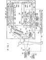
- Figure 1 is a schematic view showing an embodiment of the radiation image recording and read-out apparatus in accordance with the present invention,
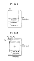
- Figures 2 and 3 are schematic views showing examples of adjustment of the radiation image recording size.
- The present invention will hereinbelow be described in further detail with reference to the accompanying drawings.
- Figure 1 shows an embodiment of the radiation image recording and read-out apparatus in accordance with the present invention, wherein a radiation image of, e.g., the frontal chest of an object in a standing position is recorded on a stimulable phosphor sheet. An image recording section 10 is positioned at the same height as that of the frontal chest of an object 1. To the image recording section 10 are fed
stimulable phosphor sheets 2 one by one from asheet case 11 or 15 in the sheet feed position. The image recording section 10 comprises a pair ofendless belts 12A and 12B for holding thesheet 2 therebetween, and an auxiliaryendless belt 13 positioned under theendless belts 12A and 12B for receiving thesheet 2 from theendless belts 12A and 12B and guiding it to aconveyer belt 14. Theconveyer belt 14 receives thesheet 2 from the image recording section 10 and conveys it to an image read outsection 20. - A
radiation source 50 for emitting a radiation such as X-rays to thesheet 2 is positioned to stand face to face with thesheet 2 held between theendless belts 12A and 12B. The radiation emitted by theradiation source 50 passes through the object 1 positioned between theradiation source 50 and thesheet 2, and a radiation image of the object 1 is stored in thesheet 2. Aneasel 51 acting as the radiation stop means is positioned between theradiation source 50 and the object 1. Theeasel 51 is driven by adrive section 52 which is controlled by a size adjusting signal Sl output by asize adjusting circuit 53 operated, for example, by a size adjusting switch positioned on an operation console. Thedrive section 52 outputs an exposure area signal S2 representing the degree of opening of theeasel 51, i.e. the radiation exposure area on thesheet 2. The exposure area signal S2 is stored in an exposure area information storage means 54 described later. To the storage means 54 is also input a sheet feed signal S3 by a drive unit 12C for theendless belt 12B. - In the image read-out
section 20, afirst feed belt 22 driven by amotor 21 and asecond feed belt 24 driven by amotor 23 are positioned in series to feed thesheet 2 at a predetermined speed in the sub-scanning direction. Between the image recording section 10 and the image read-outsection 20 is positioned anopenable shutter 3 for preventing any disturbing light from entering the image read-outsection 20 from the image recording section 10 when the radiat en image stored in thesheet 2 is read out in theimage readout section 20. In the image read-outsection 20, alayer beam source 25 is positioned above thefirst feed belt 2 and thesecond feed belt 24. There are also positioned a m .ror 26A, agalvanometer mirror 26B, a mirror 26C and a mirro: 26D for scanning thesheet 2 on thebelts layer beam 25A emitted from thelaser beam source 25. As thegalvanometer mirror 26B is swung, thesheet 2 is scanned with thelaser beam 25A in the main scanning direction. At the scanning position of thelaser beam 25A on thesheet 2 is positioned a light guidingreflection mirror 27 along the main scanning line. Thus light emitted from thesheet 2 upon stimulation thereof by thelaser beam 25A, including the light emitted therefrom and reflected by the light guidingreflection mirror 27, enters a light guidingoptical element 28 from a light input face 28A thereof. The light is guided inside of the light guidingoptical element 28 through total reflection up to alight output face 28B of the light guidingoptical element 28, and received by aphotomultiplier 29 in close contact with thelight output face 28B. In this manner, the light emitted from thesheet 2 in proportion to the radiation energy stored therein is detected and converted into an electric image signal by thephotomultiplier 29. The electric image signal thus obtained is sent to an image processing circuit (not shown) and subjected therein to required image processing. The electric image signal thus processed is then sent to an image reproducing apparatus (not shown). As bribed above, the image reproducing apparatus may be a display device such as a CRT, or may be a photographic reproducing apparatus for reproducing a visible image in a photographic film by point-by-point scanning, or may be a memory device using e.g. a magnetic tape for memorizing the electric image signal for later use in image reproduction. - The
motors drive control circuits area control circuit 57 is input. A main scanning width signal S5 generated by the stimulating ray scanningarea control circuit 57 is input to adrive circuit 26F for thegalvanometer mirror 26B. To the stimulating ray scanningarea control circuit 57 is input the exposure area signal S2 generated by the storage means 54. - In the image read-out
section 20, the scanning widths of the stimulating rays are changed in accordance with the radiation exposure area on thesheet 2 as described below. When the object 1 is positioned between theradiation source 50 and thestimulable phosphor sheet 2 held between theendless belts 12A and 12B and theradiation source 50 is activated to emit a radiation, an image of the radiation passing through the object 1 is stored in thesheet 2. At this time, the aforesaid size adjusting switch (not shown) is operated, and theeasel drive section 52 is driven by the size adjusting signal Sl generated by thesize adjusting circuit 53, thereby adjusting theeasel 51 to a desired degree of opening. The degree of opening of theeasel 51 is adjusted stepwise so that the radiation exposure area on thesheet 2 becomes equal to, for example, 356mm x 432mm, 356mm x 356mm, 254mm x 305mm, or 203mm x 254mm. Therefore, the degree of opening of theeasel 51 can be selected in accordance with the size of the image recording portion of the object 1. _ - When the degree of opening of the
easel 51 has been adjusted, theeasel drive section 52 generates the exposure area signal S2 representing the degree of opening of theeasel 51, i.e. the radiation exposure area on thesheet 2. The exposure area signal S2 is input to and stored in the storage means 54. When theendless belts 12A and 12B are rotated to feed thesheet 2 to the image read-outsection 20 after a radiation image is stored therein, the sheet feed signal S3 is generated by the drive unit 12C and sent to the storage means 54. Upon receiving the sheet feed signal S3, the storage means 54 sends the exposure area signal S2 stored in advance to the stimulating ray scanningarea control circuit 57. In this embodiment, thesheet 2 is directly fed from the image recording section 10 to the image read-outsection 20 without temporarily accumulating a number ofsuch sheets 2 therebetween. Therefore, when the sheet feed signal S3 is input to the storage means 54 and the exposure area signal S2 is output thereby, the exposure area signal S2 input to the stimulating ray scanningarea control circuit 57 always corresponds to thesheet 2 which was exposed to the radiation over the area represented by the exposure area signal S2 and which is subjected next to image read-out in the image read-outsection 20. - On the basis of the exposure area signal S2, the stimulating ray scanning
area control circuit 57 generates the sub-scanning width signal S4 and the main scanning width signal S5. The main scanning width signal S5 is sent to the galvanometermirror drive circuit 26F which changes the swing angle of thegalvanometer mirror 26B in accordance with the signal S5 so as to conduct scanning in the main scanning direction over a scanning width approximately equal to the length of the radiation exposure portion of thesheet 2 in the main scanning direction. The sub-scanning width signal S4 is sent to the motordrive control circuits sub-scanning motors sheet 2 in the sub-scanning direction over a length approximately equal to the length of the radiation exposure portion of thesheet 2 in the sub-scanning direction. Accordingly, scanning by the stimulating rays is carried out approximately over the radiation exposure area of thesheet 2, and is not unnecessarily conducted for the marginal portion where no radiation image is stored. - The
easel 51 should preferably be operated so that, as shown in Figure 2, the radiation exposure portions of all sizes on thesheets 2 align with each other at two sides. In this case, it is possible to always adjust a scanning start point Pl near the corner at which the two sides meet regardless of the sizes of the radiation exposure portions. In the case where theeasel 51 is operated such that, as shown in Figure 3, the centers of the radiation exposure portions of all sizes on thesheets 2 align with each other, it is necessary to change the scanning start point to P2, P3, P4 and P5 in accordance with the sizes of the radiation exposure- portions. For this purpose, the operations of thegalvanometer mirror 26B andmotors - In the aforesaid embodiment, the size of the radiation exposure portion on the
sheet 2 can be changed stepwise. However, it is also possible to adjust the size of the radiation exposure portion infinitely. In the case where thesheets 2 are temporarily accumulated between the image recording section 10 and the image read-outsection 20, it is possible to store the radiation exposure area information for therespective sheets 2 by combining the drive unit 12C with a sheet feed counter or the like. Further, though the exposure area signal S2 is output by thedrive section 52 for theeasel 51 in the aforesaid embodiment, it is also possible to generate the exposure area signal S2 and the size adjusting signal Sl by thesize adjusting circuit 53 and to input them in parallel into the storage means 54 and thedrive section 52. It is also possible to apply a frame plate made of lead or the like as the radiation stop means to the image recording portion of the object 1, and to operate a size input button or the like in accordance with the size of the frame plate, thereby sending the exposure area signal S2 to the storage means 54. - On the downstream side of the image read-out
section 20 is positioned afeed belt 32 driven by amotor 31.. Above thefeed belt 32 on the downstream side thereof are vertically positionedendless belts sheet 2. Further, above the group ofendless belts 33A through 33E (i.e. on the downstream side thereof) is positioned a pair ofbelts 34 which are made pivotable so that the sheet conveying direction can be changed to distribute thesheets 2 in two directions. Between the downstream end portion of the. feedbelt 32 and the lower end portion of the group ofbelts 33A through 33E is positioned aguide plate 4 for guiding thesheet 2 from the former to the latter. - In front of the pair of belts 34 (i.e. on the downstream side thereof) is positioned an erasing
section 40 comprising a pair of erasingunits unit 41 and the pair ofbelts 34, and a guide plate 6 is positioned between the inlet of the erasingunit 42 and the pair ofbelts 34. The erasingunit 41 comprises a transparentendless belt 41A and a plurality of fluorescent lamps 41B positioned inside of theendless belt 41A, and the erasingunit 42 comprises a transparentendless belt 42A and a plurality offluorescent lamps 42B positioned inside of theendless belt 42A. In the erasingsection 40, since a long time is required for erasing, the sheet feed speed must, in an apparatus having a small size, be lower than that on the upstream side of the erasingsection 40 in order that erasing can be carried out over a long time. Therefore, in the erasingsection 40, theendless belts section 40, so that at long erasing time can be obtained with short endless belts At the outlet of the erasingunits distribution plate 17 movable between two positions indicated with solid line (l7) and broken line (17') for distributing thesheets 2 conveyed out of the erasingunits guide plates sheet cases 11 and 15. Thus, thesheets 2 conveyed out of the erasingunits sheet cases 11 and 15. - In Figure 1, the
distribution plate 17 is in the position for guiding thesheets 2 into thelower sheet case 15, thelower sheet case 15 is in the position for receiving thesheets 2, and the upper sheet case 11 is in the position feeding thesheets 2 to the image recording section 10. Thesheet cases 11 and 15 alternately repeat sheet receiving and sheet feeding. More specifically, when all of thesheets 2 housed in the upper sheet case 11 have been fed one by one to the image recording section 10, the sheet case 11 is moved up to the sheet receiving position indicated by a chain line 11'. Thereafter, thesheet case 15 containing thesheets 2 in the sheet receiving position is moved up to the sheet feed position indicated by a chain line 15', and thesheets 2 are fed one by one from thesheet case 15 to the image recording section 10. Thus thesheet cases 11 and 15 are installed for movement between the sheet receiving position and the sheet feed position. When thesheets 2 are fed from either one of thesheet cases 11 and 15, the other is in the position --receiving thesheets 2. Thus, when one of thesheet cases 11 and 15 is used for sheet feeding and runs out of thesheets 2, then the positions of thesheet cases 11 and 15 are changed and thesheets 2 are fed from the other sheet case in which thesheets 2 have been accumulated. - Between the inlet portions of the erasing
units belts 34 are positionedshutters units - In the embodiment described above, the
sheet 2 in which a radiation image is stored in the image recording section 10 is passed through the image read-outsection 20,belts 33A through 33E, and the erasingsection 40, and then returned to and temporarily housed in thesheet case 11 or 15. When a predetermined number ofsheets 2 have been accumulated in thesheet case 11 or 15, thesheet case 11 or 15 is moved to the sheet feed position, and thesheets 2 are again fed one by one to the image recording section 10 and reused for image recording. - In the above-described embodiment, the
sheet cases 11 and 15 are positioned between the image recording section 10 and the erasingsection 40. However, thesheet cases 11 and 15 may be installed in any other positions, for example, in front of or at the rear of the image read-outsection 20. Further, thesheet cases 11 and 15 may not be installed at all in the apparatus. For instance, in the embodiment shown in Figure 1, thesheet cases 11 and 15 may simply be removed and a conveyor belt may be substituted therefor. - In the present invention, since a
sheet 2 once und for image recording and read-ou: is automatically conveyer to the image recording section 10 and is reused for further image recording, it is possible to use thesheet 2 repeatedly. Further, the apparatus is small in size and it is possible to increase the image recording speed. Also, since the components of the apparatus are combined into a single apparatus, the apparatus is easy to convey and to install in a mobile X-ray diagnostic station. - The apparatus as shown in Figure 1 can be modified in various ways. For example, when the aforesaid preliminary read-out and the final read-out are carried out in the image read-out
section 20, it is possible to conduct the preliminary read-out by rotating thebelts sheet 2 in the sub-scanning direction, then reversely rotate thebelts sheet 2, and again feed thesheet 2 forward to conduct the final read-out. It is also possible to carry out the final read-out when thesheet 2 is returned by reversely rotating thebelts sheet 2 forward to the next feed belt. - In the aforesaid embodiment, when the
sheet 2 is introduced into the erasingsection 40, image read-out should preferably not be conducted so that no noise is generated in the read-out image signal by strong light emitted by thefluorescent lamps 41B and 42B and entering the image read-outsection 20. Also, at this time, the power source for thephotomultiplier 29 in the image read-outsection 20 should" preferably be turned off so that no overcurrect will flow through thephotomultiplier 29.
Claims (7)
Applications Claiming Priority (2)
| Application Number | Priority Date | Filing Date | Title |
|---|---|---|---|
| JP58197193A JPS6088937A (en) | 1983-10-21 | 1983-10-21 | Radiation image information recording and reading device |
| JP197193/83 | 1983-10-21 |
Publications (3)
| Publication Number | Publication Date |
|---|---|
| EP0142709A2 true EP0142709A2 (en) | 1985-05-29 |
| EP0142709A3 EP0142709A3 (en) | 1986-04-30 |
| EP0142709B1 EP0142709B1 (en) | 1989-03-29 |
Family
ID=16370352
Family Applications (1)
| Application Number | Title | Priority Date | Filing Date |
|---|---|---|---|
| EP84112471A Expired EP0142709B1 (en) | 1983-10-21 | 1984-10-16 | Radiation image recording and read-out apparatus |
Country Status (5)
| Country | Link |
|---|---|
| US (1) | US4816676A (en) |
| EP (1) | EP0142709B1 (en) |
| JP (1) | JPS6088937A (en) |
| CA (1) | CA1223978A (en) |
| DE (1) | DE3477521D1 (en) |
Cited By (7)
| Publication number | Priority date | Publication date | Assignee | Title |
|---|---|---|---|---|
| EP0218094A1 (en) * | 1985-09-03 | 1987-04-15 | Fuji Photo Film Co., Ltd. | Radiation image recording and read-out apparatus |
| US4719356A (en) * | 1984-06-01 | 1988-01-12 | Fuji Photo Film Co., Ltd. | Endless circulating conveying system for radiation image recording and read-out apparatus |
| US4816680A (en) * | 1984-10-16 | 1989-03-28 | Fuji Photo Film Co., Ltd. | Radiation image recording and read-out apparatus |
| DE3731203A1 (en) * | 1987-09-17 | 1989-03-30 | Agfa Gevaert Ag | METHOD FOR HANDLING X-RAY TAKING CASSETTE WITH A PHOSPHOROUS FILM AND READING STATION SUITABLE FOR CARRYING OUT THE METHOD |
| EP0309874A1 (en) * | 1987-10-01 | 1989-04-05 | Agfa-Gevaert AG | Processing or handling apparatus for X-ray exposure cassettes with an exposure material in sheet form especially a phosphor coated film |
| US4960994A (en) * | 1987-09-17 | 1990-10-02 | Agfa-Gevaert Ag | X-ray cassette for sheet x-ray receiving material and method of processing the same |
| EP0414042A2 (en) * | 1989-08-21 | 1991-02-27 | Konica Corporation | x-ray film processing method, x-ray film photographing equipment, and x-ray film information processing equipment |
Families Citing this family (15)
| Publication number | Priority date | Publication date | Assignee | Title |
|---|---|---|---|---|
| JPH0690409B2 (en) * | 1985-10-17 | 1994-11-14 | 富士写真フイルム株式会社 | Radiation image information reader |
| JPH0690408B2 (en) * | 1985-10-17 | 1994-11-14 | 富士写真フイルム株式会社 | Radiation image information reader |
| JP2613049B2 (en) * | 1987-03-31 | 1997-05-21 | 富士写真フイルム株式会社 | Radiation field recognition method |
| DE58908328D1 (en) * | 1989-03-14 | 1994-10-13 | Siemens Ag | X-ray diagnostic device with a storage fluorescent screen. |
| US5231575A (en) * | 1989-10-20 | 1993-07-27 | Fuji Photo Film Co., Ltd. | Image read-out apparatus |
| US5277322A (en) * | 1992-11-25 | 1994-01-11 | Eastman Kodak Company | Pallet for holding a cassette |
| JP3275934B2 (en) * | 1994-08-18 | 2002-04-22 | 富士写真フイルム株式会社 | Radiation image reader |
| US5572037A (en) * | 1995-02-03 | 1996-11-05 | University Of Massachusetts Medical Center | Digital imaging using a scanning mirror apparatus |
| DE19860246C1 (en) * | 1998-12-24 | 2000-11-16 | Agfa Gevaert Ag | Method and device for reading information from image plates |
| JP2003098611A (en) * | 2001-09-26 | 2003-04-04 | Fuji Photo Film Co Ltd | Radiograph reader |
| JP4328640B2 (en) * | 2004-02-16 | 2009-09-09 | 富士フイルム株式会社 | Image forming apparatus and transport method thereof |
| JP4776589B2 (en) * | 2007-06-19 | 2011-09-21 | 敏彦 仁科 | Auxiliary container for drug use |
| JP4764462B2 (en) * | 2008-06-11 | 2011-09-07 | 豊彦 岸本 | Tablet cup and its mounting member |
| FI20086241L (en) * | 2008-12-23 | 2010-06-24 | Palodex Group Oy | Image disc reader |
| FI20086240A (en) | 2008-12-23 | 2010-06-24 | Palodex Group Oy | Image plate reader device cleaning system |
Citations (1)
| Publication number | Priority date | Publication date | Assignee | Title |
|---|---|---|---|---|
| EP0077678A2 (en) * | 1981-10-16 | 1983-04-27 | Fuji Photo Film Co., Ltd. | Radiation image recording and read-out system |
Family Cites Families (15)
| Publication number | Priority date | Publication date | Assignee | Title |
|---|---|---|---|---|
| JPS5944333B2 (en) * | 1978-07-12 | 1984-10-29 | 富士写真フイルム株式会社 | Radiographic image conversion method |
| JPS5512429A (en) * | 1978-07-12 | 1980-01-29 | Fuji Photo Film Co Ltd | Radioactive image reader |
| NL7905433A (en) * | 1978-07-12 | 1980-01-15 | Fuji Photo Film Co Ltd | METHOD AND APPARATUS FOR RECORDING AND DISPLAYING A RADIATION IMAGE |
| US4284889A (en) * | 1978-10-05 | 1981-08-18 | Fuji Photo Film Co., Ltd. | Method for recording radiation image using stimulable phosphor |
| US4315318A (en) * | 1978-12-26 | 1982-02-09 | Fuji Photo Film Co., Ltd. | Method and apparatus for processing a radiation image |
| JPS55116340A (en) * | 1979-02-28 | 1980-09-06 | Fuji Photo Film Co Ltd | Method and device for processing gradation of radiation picture |
| DE2925274A1 (en) * | 1979-06-22 | 1981-01-08 | Siemens Ag | X-RAY DIAGNOSTIC SYSTEM FOR ANGIOGRAPHIC X-RAY RECORDING SERIES |
| JPS5611392A (en) * | 1979-07-11 | 1981-02-04 | Fuji Photo Film Co Ltd | Method and device for converting radiation image |
| JPS56104645A (en) * | 1979-12-25 | 1981-08-20 | Fuji Photo Film Co Ltd | Radiation picture treating method and its device |
| JPS5814129A (en) * | 1981-07-17 | 1983-01-26 | Hitachi Medical Corp | X-ray fluorographic device |
| JPS5866935A (en) * | 1981-10-16 | 1983-04-21 | Fuji Photo Film Co Ltd | Radiation picture information recording and reading device |
| JPS5866934A (en) * | 1981-10-16 | 1983-04-21 | Fuji Photo Film Co Ltd | Radiation picture information recording and reading device |
| JPS5866931A (en) * | 1981-10-16 | 1983-04-21 | Fuji Photo Film Co Ltd | Radiation picture information recording and reading device |
| JPS5889245A (en) * | 1981-11-25 | 1983-05-27 | 富士写真フイルム株式会社 | Reading out of radioactive image information |
| JPH0779402B2 (en) * | 1981-12-04 | 1995-08-23 | 富士ゼロックス株式会社 | Cut paper facsimile |
-
1983
- 1983-10-21 JP JP58197193A patent/JPS6088937A/en active Granted
-
1984
- 1984-10-16 EP EP84112471A patent/EP0142709B1/en not_active Expired
- 1984-10-16 DE DE8484112471T patent/DE3477521D1/en not_active Expired
- 1984-10-17 US US06/661,755 patent/US4816676A/en not_active Expired - Lifetime
- 1984-10-18 CA CA000465817A patent/CA1223978A/en not_active Expired
Patent Citations (1)
| Publication number | Priority date | Publication date | Assignee | Title |
|---|---|---|---|---|
| EP0077678A2 (en) * | 1981-10-16 | 1983-04-27 | Fuji Photo Film Co., Ltd. | Radiation image recording and read-out system |
Cited By (9)
| Publication number | Priority date | Publication date | Assignee | Title |
|---|---|---|---|---|
| US4719356A (en) * | 1984-06-01 | 1988-01-12 | Fuji Photo Film Co., Ltd. | Endless circulating conveying system for radiation image recording and read-out apparatus |
| US4816680A (en) * | 1984-10-16 | 1989-03-28 | Fuji Photo Film Co., Ltd. | Radiation image recording and read-out apparatus |
| EP0218094A1 (en) * | 1985-09-03 | 1987-04-15 | Fuji Photo Film Co., Ltd. | Radiation image recording and read-out apparatus |
| DE3731203A1 (en) * | 1987-09-17 | 1989-03-30 | Agfa Gevaert Ag | METHOD FOR HANDLING X-RAY TAKING CASSETTE WITH A PHOSPHOROUS FILM AND READING STATION SUITABLE FOR CARRYING OUT THE METHOD |
| US4893011A (en) * | 1987-09-17 | 1990-01-09 | Agfa-Gevaert Ag | Method of processing X-ray film cassettes with phosporus-coated films and a reading station for executing the process |
| US4960994A (en) * | 1987-09-17 | 1990-10-02 | Agfa-Gevaert Ag | X-ray cassette for sheet x-ray receiving material and method of processing the same |
| EP0309874A1 (en) * | 1987-10-01 | 1989-04-05 | Agfa-Gevaert AG | Processing or handling apparatus for X-ray exposure cassettes with an exposure material in sheet form especially a phosphor coated film |
| EP0414042A2 (en) * | 1989-08-21 | 1991-02-27 | Konica Corporation | x-ray film processing method, x-ray film photographing equipment, and x-ray film information processing equipment |
| EP0414042A3 (en) * | 1989-08-21 | 1991-04-10 | Konica Corporation | X-ray film processing method, x-ray film photographing equipment, and x-ray film information processing equipment |
Also Published As
| Publication number | Publication date |
|---|---|
| EP0142709A3 (en) | 1986-04-30 |
| JPH0347488B2 (en) | 1991-07-19 |
| JPS6088937A (en) | 1985-05-18 |
| DE3477521D1 (en) | 1989-05-03 |
| CA1223978A (en) | 1987-07-07 |
| US4816676A (en) | 1989-03-28 |
| EP0142709B1 (en) | 1989-03-29 |
Similar Documents
| Publication | Publication Date | Title |
|---|---|---|
| US4851679A (en) | Radiation image recording and read-out apparatus | |
| US4816676A (en) | Radiation image recording and read-out apparatus including radiation stop and scan area control means | |
| EP0125800B1 (en) | Radiation image recording and read-out apparatus | |
| US4496973A (en) | Radiation image read-out method and apparatus | |
| US4578582A (en) | Radiation image recording and reproducing system with preferential processing function | |
| EP0077677A2 (en) | Radiation image read-out method and apparatus | |
| US4710626A (en) | Radiation image recording and read-out method and apparatus | |
| US4527061A (en) | Radiation image read-out method and apparatus | |
| EP0182099B1 (en) | Radiation image recording and read-out apparatus | |
| US4581535A (en) | Method of recording X-ray image | |
| US4814618A (en) | Radiation image read-out method and radiation image recording read-out apparatus | |
| EP0172417B1 (en) | Radiation image recording and read-out apparatus | |
| EP0145982A1 (en) | Method of adjusting scale factor for radiation image | |
| US4568832A (en) | Radiation image read-out method and apparatus | |
| EP0218094B1 (en) | Radiation image recording and read-out apparatus | |
| JPH0588451B2 (en) | ||
| JPH0584499B2 (en) | ||
| JPS60194442A (en) | Radiation picture information recorder and reader | |
| JPS6199140A (en) | Traveling medical examination car | |
| JPS61236887A (en) | Apparatus for recording and reading radiation image information | |
| JPH0412970B2 (en) | ||
| JPH0678907A (en) | Subtraction image forming apparatus | |
| JPH0552935B2 (en) | ||
| JPH03171131A (en) | Method for using rolled accumulating phosphor sheet and accumulating phosphor sheet loader and radiograph information recorder | |
| JPS6237899A (en) | Recording device for radiation image information |
Legal Events
| Date | Code | Title | Description |
|---|---|---|---|
| PUAI | Public reference made under article 153(3) epc to a published international application that has entered the european phase |
Free format text: ORIGINAL CODE: 0009012 |
|
| AK | Designated contracting states |
Designated state(s): BE DE FR GB NL |
|
| PUAL | Search report despatched |
Free format text: ORIGINAL CODE: 0009013 |
|
| AK | Designated contracting states |
Kind code of ref document: A3 Designated state(s): BE DE FR GB NL |
|
| RHK1 | Main classification (correction) |
Ipc: G03B 42/02 |
|
| 17P | Request for examination filed |
Effective date: 19860606 |
|
| 17Q | First examination report despatched |
Effective date: 19870702 |
|
| GRAA | (expected) grant |
Free format text: ORIGINAL CODE: 0009210 |
|
| AK | Designated contracting states |
Kind code of ref document: B1 Designated state(s): BE DE FR GB NL |
|
| REF | Corresponds to: |
Ref document number: 3477521 Country of ref document: DE Date of ref document: 19890503 |
|
| ET | Fr: translation filed | ||
| PLBE | No opposition filed within time limit |
Free format text: ORIGINAL CODE: 0009261 |
|
| STAA | Information on the status of an ep patent application or granted ep patent |
Free format text: STATUS: NO OPPOSITION FILED WITHIN TIME LIMIT |
|
| 26N | No opposition filed | ||
| REG | Reference to a national code |
Ref country code: GB Ref legal event code: IF02 |
|
| PGFP | Annual fee paid to national office [announced via postgrant information from national office to epo] |
Ref country code: NL Payment date: 20031002 Year of fee payment: 20 |
|
| PGFP | Annual fee paid to national office [announced via postgrant information from national office to epo] |
Ref country code: GB Payment date: 20031008 Year of fee payment: 20 |
|
| PGFP | Annual fee paid to national office [announced via postgrant information from national office to epo] |
Ref country code: FR Payment date: 20031020 Year of fee payment: 20 |
|
| PGFP | Annual fee paid to national office [announced via postgrant information from national office to epo] |
Ref country code: BE Payment date: 20031125 Year of fee payment: 20 |
|
| PGFP | Annual fee paid to national office [announced via postgrant information from national office to epo] |
Ref country code: DE Payment date: 20031201 Year of fee payment: 20 |
|
| PG25 | Lapsed in a contracting state [announced via postgrant information from national office to epo] |
Ref country code: GB Free format text: LAPSE BECAUSE OF EXPIRATION OF PROTECTION Effective date: 20041015 |
|
| PG25 | Lapsed in a contracting state [announced via postgrant information from national office to epo] |
Ref country code: NL Free format text: LAPSE BECAUSE OF EXPIRATION OF PROTECTION Effective date: 20041016 |
|
| BE20 | Be: patent expired |
Owner name: *FUJI PHOTO FILM CO. LTD Effective date: 20041016 |
|
| REG | Reference to a national code |
Ref country code: GB Ref legal event code: PE20 |
|
| NLV7 | Nl: ceased due to reaching the maximum lifetime of a patent |
Effective date: 20041016 |