EP0136855A2 - Electrosurgical generator - Google Patents
Electrosurgical generator Download PDFInfo
- Publication number
- EP0136855A2 EP0136855A2 EP84306208A EP84306208A EP0136855A2 EP 0136855 A2 EP0136855 A2 EP 0136855A2 EP 84306208 A EP84306208 A EP 84306208A EP 84306208 A EP84306208 A EP 84306208A EP 0136855 A2 EP0136855 A2 EP 0136855A2
- Authority
- EP
- European Patent Office
- Prior art keywords
- load
- generator
- power
- impedance
- correction factor
- Prior art date
- Legal status (The legal status is an assumption and is not a legal conclusion. Google has not performed a legal analysis and makes no representation as to the accuracy of the status listed.)
- Granted
Links
Images


Classifications
-
- A—HUMAN NECESSITIES
- A61—MEDICAL OR VETERINARY SCIENCE; HYGIENE
- A61B—DIAGNOSIS; SURGERY; IDENTIFICATION
- A61B18/00—Surgical instruments, devices or methods for transferring non-mechanical forms of energy to or from the body
- A61B18/04—Surgical instruments, devices or methods for transferring non-mechanical forms of energy to or from the body by heating
- A61B18/12—Surgical instruments, devices or methods for transferring non-mechanical forms of energy to or from the body by heating by passing a current through the tissue to be heated, e.g. high-frequency current
- A61B18/1206—Generators therefor
-
- A—HUMAN NECESSITIES
- A61—MEDICAL OR VETERINARY SCIENCE; HYGIENE
- A61B—DIAGNOSIS; SURGERY; IDENTIFICATION
- A61B18/00—Surgical instruments, devices or methods for transferring non-mechanical forms of energy to or from the body
- A61B2018/00636—Sensing and controlling the application of energy
- A61B2018/00696—Controlled or regulated parameters
- A61B2018/00702—Power or energy
-
- A—HUMAN NECESSITIES
- A61—MEDICAL OR VETERINARY SCIENCE; HYGIENE
- A61B—DIAGNOSIS; SURGERY; IDENTIFICATION
- A61B18/00—Surgical instruments, devices or methods for transferring non-mechanical forms of energy to or from the body
- A61B2018/00636—Sensing and controlling the application of energy
- A61B2018/00773—Sensed parameters
- A61B2018/00779—Power or energy
-
- A—HUMAN NECESSITIES
- A61—MEDICAL OR VETERINARY SCIENCE; HYGIENE
- A61B—DIAGNOSIS; SURGERY; IDENTIFICATION
- A61B18/00—Surgical instruments, devices or methods for transferring non-mechanical forms of energy to or from the body
- A61B2018/00636—Sensing and controlling the application of energy
- A61B2018/00773—Sensed parameters
- A61B2018/00827—Current
-
- A—HUMAN NECESSITIES
- A61—MEDICAL OR VETERINARY SCIENCE; HYGIENE
- A61B—DIAGNOSIS; SURGERY; IDENTIFICATION
- A61B18/00—Surgical instruments, devices or methods for transferring non-mechanical forms of energy to or from the body
- A61B2018/00636—Sensing and controlling the application of energy
- A61B2018/00773—Sensed parameters
- A61B2018/00875—Resistance or impedance
-
- A—HUMAN NECESSITIES
- A61—MEDICAL OR VETERINARY SCIENCE; HYGIENE
- A61B—DIAGNOSIS; SURGERY; IDENTIFICATION
- A61B18/00—Surgical instruments, devices or methods for transferring non-mechanical forms of energy to or from the body
- A61B2018/00636—Sensing and controlling the application of energy
- A61B2018/00773—Sensed parameters
- A61B2018/00892—Voltage
Definitions
- This invention relates to electrosurgical generators and in particular to such generators including means for controlling the output power level thereof.
- the invention further relates to the use of such generators with bipolar forceps or handpieces.
- Bipolar electrosurgery refers to the use of a handpiece having two small electrodes to apply electrosurgical current instead of a single small active and a large return electrode as is used in monopolar electrosurgery.
- Bipolar electrosurgery is used extensively in surgical procedures on the eye and brain where the delicate tissue can be easily damaged by excessive heat or sparking.
- an electrosurgical generator comprising:-
- the arrangement is such that the power decreases as the inverse of the square of the patient's tissue impedance.
- an electrosurgical generator comprising:-
- the arrangement is such that, for impedances above a predetermined value, one of two different modes of operation may be selected.
- one of the selected modes provides a constant voltage characteristic, and the other the characteristic described above where the power is decreased in accordance with the square of the load impedance.
- the generator is operable to compute a required power for different load impedance ranges, and includes circuitry for conforming the actual output power to the computed required power.
- an electrosurgical generator comprising:-
- U.S. patents 3,946,487; 3,980,085; 4,188,927, and 4,092,986 disclose means for reducing the output current in accordance with increasing load impedance.
- these patents teach the use of constant voltage outputs whereby the current is decreased with increasing load impedance.
- output power be inversely varied in accordance with the square of the load impedance.
- output power be decreased at a rate which is substantially greater than that which results in the constant voltage outputs of these patents.
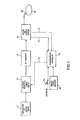
- an illustrative electrosurgical generator in accordance with the invention includes a switching regulated power supply 10, an unregulated DC voltage source 11, an RF generator 12, voltage and current sensors 14, a microprocessor controller 16, a nominal power indicator 18, and a foot- switch 20. Electrosurgical current is applied from the generator to forceps 22, which are diagramatically shown in contact with a patient 24.
- the power delivered to the load is a function of the voltage from DC supply 10 and the load impedance.
- sensors 14 develop sensing signals proportional to the load voltage and current which are respectively applied over lines 15 and 17 to controller 16.
- the controller digitizes the sensing signals and computes the load impedance and the actual power being delivered to the load.
- a required load power is also calculated which is a function of the calculated load impedance and the nominal power selected by the operator at 18.
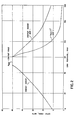
- a graph of the required load power for a nominal power of 50 watts is illustrated in Figure 2.
- the computed required power is reduced to prevent damage or overheating of the RF output.
- the control voltage applied over line 19 to supply 10 controls the output power in such a manner as to maintain the load current constant over this low value impedance range.
- the computed required power is held constant at the selected nominal power.
- one of two modes may be chosen by the operator.
- the computed required power is reduced in the first of these modes with the voltage being held constant, this effect being similar to that of known generators.
- the computed required power is reduced at a rate which is substantially greater than that which occurs when the voltage is held constant.
- the computed required power is reduced, in the second mode, as the square of the load impedance.
- the computed required power for a load having impedance of 200 ohms is one-fourth that required for a load impedance of 100 ohms.
- the impedance is increased to about 800 ohms, for example, in the second mode of operation, a constant voltage characteristic may be implemented since at this level, the power levels may become impractically small.
- the load impedance varies continuously, during electrosurgery due to differing amounts of tissue contact, tissue heating, etc.
- the microprocessor controller 16 accordingly repeats the measurement, calculation and correction process approximately every 20 milliseconds as long as the foot switch 20 or bipolar handswitch (not shown) is closed.
- FIG. 3 is a generalized flow-chart of the program executed by microprocessor controller 16 where the microprocessor may be an INTEL 8039, a member of the 8048 family of single-chip microcomputers and where the program may be stored on an INTEL 2716 programmable memory.
- program control pases to routine COLDST 26 (COLD START), which calculates certain parameters and initiates certain functions.
- I MAX' is the current value which should occur at 70 ohms for a given nominal power selected by the operator.
- I MAX (P MAX /70) 1/2 where P MAX equals the nominal power selected by the operator and 70 corresponds to a 70 ohm load.
- V MAX and I MAX COLDST After the calculations of V MAX and I MAX COLDST applies a small control voltage AFB over line 19 to supply 10 to turn on RF generator 12. It then waits for about 0.01 second to allow the RF output to become stable before transferring a control to the control routines, GETPWR 28 and CNTLP 30.
- GETPWR detects the load voltage signal V SEN occuring at line 15 and the load current signal I sen occuring at line 17.
- the load power P LOAD is calculated as V SEN I SEN .
- the load impedance ZLOAD is calculated as VSEN/ISEN. A determination is also made as to which impedance range the load impedance occurs in.
- a first impedance range flag (not shown) is set if the load impedance range is less than 70 ohms, a second flag is set if it is between 70 and 100 ohms, and a third flag is set if it is above 100 ohms. It should be understood a substantial amount of tolerance may be employed in the selection of the impedance range may extend from 60 to 115 ohms, for example.
- the operator may select between one of two different modes in the high impedance range.
- a further flag will be set by COLDST indicating the selected mode.
- the routine CNTLP inspects the above flags and determines which of the following algorithms should be executed. These algorithms are LOZ 32, MIDZ 36, ZOL 38, and HIZ R 2 40 as can be seen in Figure 3. All of these algorithms eventually pass control to a routine AFBADJ 34. Each of these routines will now be individually discussed.
- CNTLP will transfer control to LOZ 32.
- a correction factor will be computed which will implement the constant current characteristic described above for the low impedance range.
- the calculated factor equals 1.0/1.2.
- AFBADJ 34 raises or lowers the control voltage AFB based on the computed correction factor.
- the value of AF B is 10 volts, it will be reduced by the correction factor of 1.0/1.2.
- the current is maintained constant at the value of I MAX (1.0 amp) over the low impedance range.
- I MAX 1.0 amp
- the correction factor is calculated as IMAX/ISEN over the entire low impedance range by the LOZ routine.
- a test is made to determine if the operator is still enabling the generator to apply electrosurgical power to the forceps. This test is conducted at 42. If the generator is so enabled, control is returned to GETPWR. Execution of the routines from GETPWR through AFBADJ requires at most about 20 milliseconds and thus the power delivered to the load is constantly being adjusted depending upon the sensed load conditions. If there are no more enables, the routine may return to an initialization mode where the output is set off and certain self-test routines are executed while waiting for the next enable. This feature is not shown in the flow chart of Figure 3.
- control is passed to the AFBADJ routine 34 where the correction factor is multiplied by the previous value of control voltage AFB applied to line 19.
- the adjustment of the control voltage and the application over line 19 is executed in the same manner as described above for the LOZ routine.
- the impedance With the passage of further time the impedance continues to increase. Thus, assuming the desiccation mode is still enabled by the operator, control will be returned to GETPWR and CNTLP. Further, assuming the operator has selected mode one for the high range impedances, CNTLP 30 will transfer control to ZOL 38 after having sensed the appropriate flags. If the impedance calculated by GETPWR is now 200 ohms, the power delivered to it will have a constant voltage characteristic as described above with respect to Figure 2. In-particular, the constant voltage will be V MAX as calculated by the COLDST routine. In order to implement this constant voltage characteristic ZOL calculates a correction factor determined by the expression V MAX /V SEN where V SEN equals the load voltage sensed by GETPWR. If the sensed voltage is 70 volts while V MAX is 50 volts, the correction factor will be 5/7. AFBADJ utilizes this correction factor in the same manner as discussed above for LOZ and MIDZ to adjust the control voltage applied
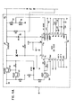
- FIG. 4A and 4B is a schematic diagram of switching power supply 10, high efficiency RF generator 12, and current sensors 14 of Figure 1.
- the switching power supply includes a standard switching supply circuit 44 made by Silicon General. The remaining integrated circuits of the invention are also made by Silicon.General and other such companies.
- the switching power supply is of conventional configuration and includes a switching transistor 46 and inductor 47, and an output line 48 which applies regulated high voltage to output transistor 52 of generator 12.
- the power supply voltage applied to line 48 originates from terminal 50, this voltage typically being about 100 volts.
- the voltage at terminal 50 is regulated by switching transistor 46, inductor 47 and capacitor 49 where, in particular, the longer transistor 46 is switched off, the less the DC voltage applied to line 48 will be in magnitude.
- a voltage DC SENSE proportional to the line 48 voltage is applied to terminal 2 of circuit 44 via a voltage divider comprising resistors 54 and 56. This voltage is compared to and follows AFB on line 19.
- On-off pulses are applied to switching transistor 46 from circuit 44 via transistors 58 and.60.
- the repetition rate of these pulses is determined by resistor 62 and capacitor 64 connected to the R T and C T terminals of circuit 44.
- the width of these pulses and thus the on/off time of transistor 46 is a function of the difference between AFB and DC SENSE.
- the power supply voltage follows AFB as the impedance changes during a desiccation procedure.
- the output power is delivered to the load via lines 66 and 68 which in turn are connected to output transformer 70.
- the generator 12 is driven by a 750 KHz signal applied to terminal 72 where it is amplified and the applied to output transistor 52 which in turn drives prilrary winding 74 of transformer 70.
- the load current is sensed at transformer 76 and converted to a voltage representative of the current by the conversion circuitry indicated at 78. This voltage is applied over line 17 as the I SEN signal of the microprocessor 16. Furthermore, a voltage representative of the load voltage is derived from winding 80 of transformer 70. This signal is converted by signal conversion circuitry 82 to develop the load. voltage at V SEN on line 19.
- resistors are in ohms while those for the capacitances are microfarads unless otherwise specified, these values being illustrative of the embodiment of the invention.
Abstract
Description
- This invention relates to electrosurgical generators and in particular to such generators including means for controlling the output power level thereof. The invention further relates to the use of such generators with bipolar forceps or handpieces.
- Bipolar electrosurgery refers to the use of a handpiece having two small electrodes to apply electrosurgical current instead of a single small active and a large return electrode as is used in monopolar electrosurgery.
- The advantages of bipolar electrosurgery over monopolar are:-
- (1) A lower power level is used which translates directly to less tissue destruction.
- (2) The only tissue destroyed is that located between the bipolar electrodes so that there is virtually no danger of alternate site burns.
- (3) The applied voltage can be much lower. This prevents tissue charring and scarring due to sparks at the electrodes.
- Bipolar electrosurgery is used extensively in surgical procedures on the eye and brain where the delicate tissue can be easily damaged by excessive heat or sparking.
- In an effort to improve the effects of bipolar electrosurgery, studies have been conducted on the variation of tissue impedance during desiccation. The results showed two phases of desiccation. The first phase begins as soon as electrosurgical power is applied. The tissue temperature rises, cell walls are ruptured and the impedance of the tissue shows a decrease. The temperature continues to rise and the water is driven off as steam. As tissue dries out, the resistance rises. The output voltage goes up somewhat as the resistance rises and at this point sparking, excessive heating of the forceps, or sticking of forceps to tissue may occur.
- According to a first aspect of the invention there is provided an electrosurgical generator comprising:-
- a source of electrosurgical energy;
- means adapted for connecting said source to a patient; and
- control means for decreasing the output power from said source with increasing patient impedance, the rate of power decrease being substantially greater than that which would result if the output voltage from the source were maintained constant over the range of increasing patient impedance.
- Thus it will be seen that the power diminishes towards the end of the desiccation stage.
- Preferably the arrangement is such that the power decreases as the inverse of the square of the patient's tissue impedance.
- According to a second aspect of the invention there is provided an electrosurgical generator comprising:-
- an adjustable source of electrosurgical energy;
- means adapted for connecting said source to a load including a patient; and
- control means for adjusting the actual power delivered to said load from said source including:-
- means for determing the impedance of said load;
- means for computing a correction factor depending on the value of said impedance, said correction factor corresponding to a required load power; and
- means responsive to said correction factor for adjusting said source of electrosurgical power so that said actual power follows said required power.
- Preferably the arrangement is such that, for impedances above a predetermined value, one of two different modes of operation may be selected. Preferably one of the selected modes provides a constant voltage characteristic, and the other the characteristic described above where the power is decreased in accordance with the square of the load impedance.
- In a preferred embodiment, the generator is operable to compute a required power for different load impedance ranges, and includes circuitry for conforming the actual output power to the computed required power.
- According to a third aspect of the invention there is provided an electrosurgical generator comprising:-
- an adjustable source of electrosurgical energy;
- means adapted for connecting said source to a load including a patient; and
- control means for adjusting the power delivered to said load from said source including:-
- means for selecting first and second modes of operation of said generator when said load impedance exceeds a predetermined value;
- means for maintaining the voltage across said load substantially constant for all values of load impedance in excess of said predetermined value in response to said first mode being selected, and
- means for reducing the power delivered to said load in accordance with the inverse of the square of the load impedance for all values of load impedance in excess of said predetermined value in response to said second mode being selected.
- U.S. patents 3,946,487; 3,980,085; 4,188,927, and 4,092,986 disclose means for reducing the output current in accordance with increasing load impedance. In particular, these patents teach the use of constant voltage outputs whereby the current is decreased with increasing load impedance. However, there is not disclosure in these patents that output power be inversely varied in accordance with the square of the load impedance. In general, there is no disclosure that output power be decreased at a rate which is substantially greater than that which results in the constant voltage outputs of these patents.
- In order that the invention may be better understood an embodiment thereof will now be described by way of example only and with reference to the accompanying drawings in which:-
- Figure 1 is a block diagram of an embodiment of an electrosurgical generator in accordance with the invention;
- Figure 2 is a graph illustrating different modes of operation of the generator of the present invention;
- Figure 3 is a flow chart of the program executed by and stored in the microprocessor controller of Figure 1; and
- Figures 4A and 4B are a schematic diagram of the switching power supply, the generator and the voltage and current sensing circuitry of Figure 1.
- Referring to Figure 1, an illustrative electrosurgical generator in accordance with the invention includes a switching regulated
power supply 10, an unregulated DC voltage source 11, anRF generator 12, voltage andcurrent sensors 14, amicroprocessor controller 16, anominal power indicator 18, and a foot-switch 20. Electrosurgical current is applied from the generator to forceps 22, which are diagramatically shown in contact with apatient 24. - The power delivered to the load is a function of the voltage from
DC supply 10 and the load impedance. As will be described in more detail hereinafter,sensors 14 develop sensing signals proportional to the load voltage and current which are respectively applied overlines - A required load power is also calculated which is a function of the calculated load impedance and the nominal power selected by the operator at 18. A graph of the required load power for a nominal power of 50 watts is illustrated in Figure 2.
- At low load impedances less than typically 70 ohms, the computed required power is reduced to prevent damage or overheating of the RF output. In particular, the control voltage applied over
line 19 to supply 10 controls the output power in such a manner as to maintain the load current constant over this low value impedance range. Over a mid range extending from about 70 to 100 ohms, the computed required power is held constant at the selected nominal power. - At impedances above 100 ohms, one of two modes may be chosen by the operator. As indicated in Figure 2, the computed required power is reduced in the first of these modes with the voltage being held constant, this effect being similar to that of known generators. In the second mode the computed required power is reduced at a rate which is substantially greater than that which occurs when the voltage is held constant. Preferably, the computed required power is reduced, in the second mode, as the square of the load impedance. Thus, for example, the computed required power for a load having impedance of 200 ohms is one-fourth that required for a load impedance of 100 ohms. When the impedance is increased to about 800 ohms, for example, in the second mode of operation, a constant voltage characteristic may be implemented since at this level, the power levels may become impractically small.
- After the required power has been calculated for a given nominal power and load impedance range, a comparison is then effectively made between the required power and the actual power to adjust the control voltage applied to
line 19 by the correct amount to cause the actual power to match the required power. - The load impedance varies continuously, during electrosurgery due to differing amounts of tissue contact, tissue heating, etc. The
microprocessor controller 16 accordingly repeats the measurement, calculation and correction process approximately every 20 milliseconds as long as thefoot switch 20 or bipolar handswitch (not shown) is closed. - Reference should now be made to Figure 3, which is a generalized flow-chart of the program executed by
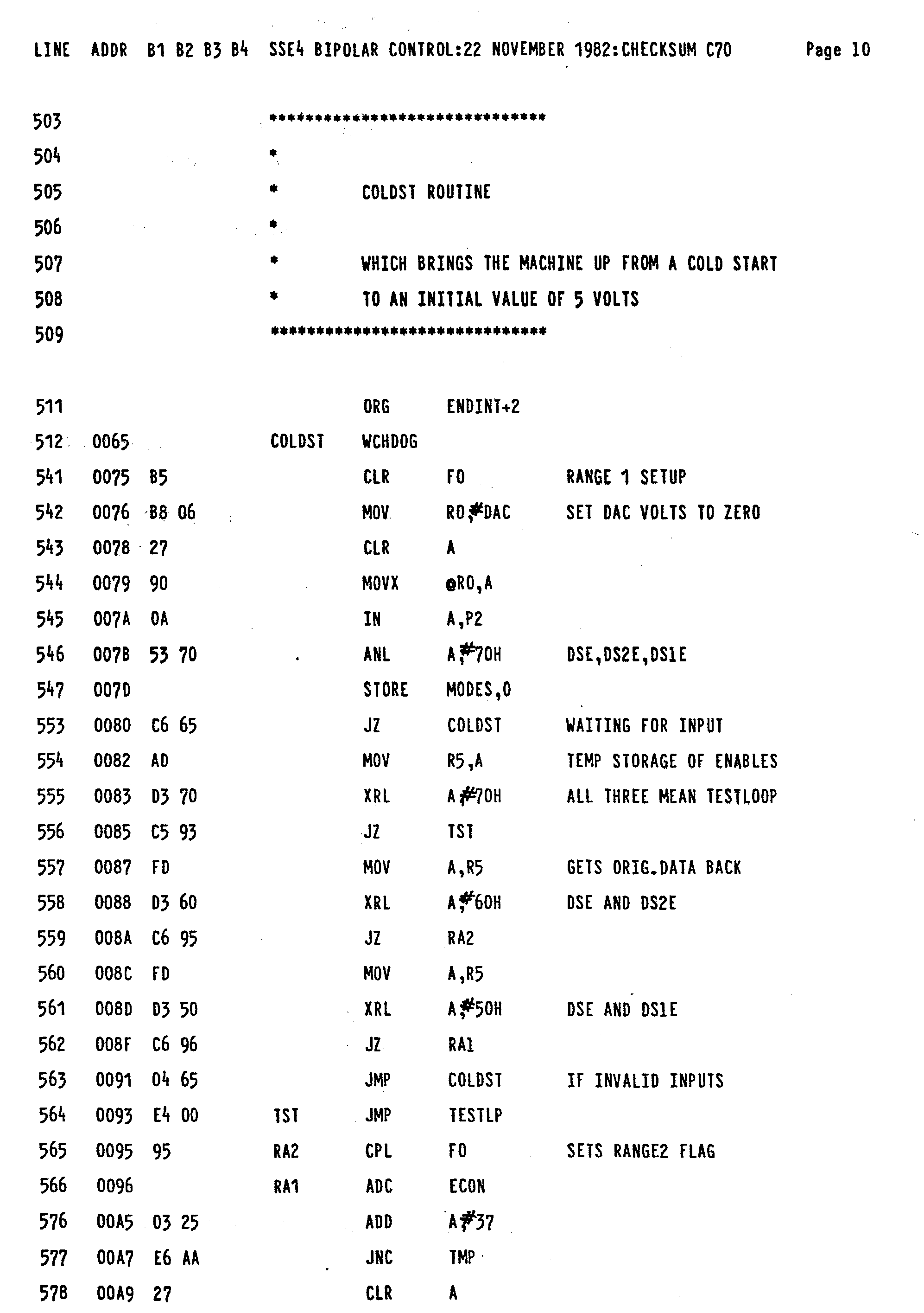
microprocessor controller 16 where the microprocessor may be an INTEL 8039, a member of the 8048 family of single-chip microcomputers and where the program may be stored on an INTEL 2716 programmable memory. After certain initialization routines (not shown), program control pases to routine COLDST 26 (COLD START), which calculates certain parameters and initiates certain functions. First it calculates IMAX' which is the current value which should occur at 70 ohms for a given nominal power selected by the operator. For example, if the operator selects a nominal power of 70 watts, the current delivered to a 70 ohm load will be 1 ampere and thus IMAX is 1 ampere in this case. The nominal power range available to the operator typically extends from 0 to 70 watts. The nominal power selected by the operator is termed PMAX and occurs over the mid range impedance extending from 70 to 100 ohms. Since the maximum power occurs over the 70 to 100 ohm range, and since the largest current which will occur in this range occurs at 70 ohms, IMAX is calculated at 70 ohms as described above. In general, IMAX=(PMAX/70)1/2 where PMAX equals the nominal power selected by the operator and 70 corresponds to a 70 ohm load. - COLDST also calculates the initial parameter Vmax in the following manner. Assume the operator selects a nominal power of 25 watts. The voltage occuring across a 100 ohm load for this wattage corresponds to VMAX, thus in this case VMAX would be 50 volts. As stated above PMAX occurs over the 70 to 100 ohm range. Further, the maximum voltage will occur with a 100 ohm load. Accordingly, VMAX is calculated in the foregoing manner. In general, VMAX=(100 PMAX)1/2 =10(PMAX)1/2.
- After the calculations of VMAX and IMAX COLDST applies a small control voltage AFB over
line 19 to supply 10 to turn onRF generator 12. It then waits for about 0.01 second to allow the RF output to become stable before transferring a control to the control routines,GETPWR 28 andCNTLP 30. GETPWR detects the load voltage signal VSEN occuring atline 15 and the load current signal Isen occuring atline 17. The load power P LOAD is calculated as V SENISEN. Furthermore, the load impedance ZLOAD is calculated as VSEN/ISEN. A determination is also made as to which impedance range the load impedance occurs in. Thus, a first impedance range flag (not shown) is set if the load impedance range is less than 70 ohms, a second flag is set if it is between 70 and 100 ohms, and a third flag is set if it is above 100 ohms. It should be understood a substantial amount of tolerance may be employed in the selection of the impedance range may extend from 60 to 115 ohms, for example. - As stated above the operator may select between one of two different modes in the high impedance range. Depending upon the selected mode, a further flag will be set by COLDST indicating the selected mode. The routine CNTLP inspects the above flags and determines which of the following algorithms should be executed. These algorithms are LOZ 32,
MIDZ 36,ZOL 38, andHIZ R2 40 as can be seen in Figure 3. All of these algorithms eventually pass control to aroutine AFBADJ 34. Each of these routines will now be individually discussed. - Assuming the load impedance is measured as 40 ohms, CNTLP will transfer control to LOZ 32. A correction factor will be computed which will implement the constant current characteristic described above for the low impedance range. In particular, if ISEN-1.2 amps and if IMAX=1 amp (for example), then the correction factor is computed as IMAX/ISEN. Thus, the calculated factor equals 1.0/1.2. After calculation of the correction factor control is passed to AFBADJ 34 which raises or lowers the control voltage AFB based on the computed correction factor. Thus, if the value of AFB is 10 volts, it will be reduced by the correction factor of 1.0/1.2. In this manner the current is maintained constant at the value of IMAX (1.0 amp) over the low impedance range. Note in this example that ISEN exceeds IMAX. Whether it exceeded it or not, the correction factor is calculated as IMAX/ISEN over the entire low impedance range by the LOZ routine.
- After the corrected control voltage is applied over
line 19 to supply 10, a test is made to determine if the operator is still enabling the generator to apply electrosurgical power to the forceps. This test is conducted at 42. If the generator is so enabled, control is returned to GETPWR. Execution of the routines from GETPWR through AFBADJ requires at most about 20 milliseconds and thus the power delivered to the load is constantly being adjusted depending upon the sensed load conditions. If there are no more enables, the routine may return to an initialization mode where the output is set off and certain self-test routines are executed while waiting for the next enable. This feature is not shown in the flow chart of Figure 3. - As stated above the impedance of the tissue will tend to increase as desiccation proceeds. Hence, assume the next load measured by the GETPWR routine is 80 ohms. The MIDZ flag would be set and the load power calculated. the routine CNTLP would again determine the actuated flags and transfer control to the
MIDZ routine 36. There a correction factor is calculated in accordance with the expression (PMAX/PLOAD)1/2 where PMAX equals the nominal power selected by the operator and PLOAD= V SEN I SEN as calculated in GETPWR. Thus, if PLOAD, the actual load power, is 60 watts and PMAX the nominal power is 70 watts, the calculated correction factor is (7/6)1/2. Once this correction factor has been determined, control is passed to the AFBADJ routine 34 where the correction factor is multiplied by the previous value of control voltage AFB applied toline 19. The adjustment of the control voltage and the application overline 19 is executed in the same manner as described above for the LOZ routine. - With the passage of further time the impedance continues to increase. Thus, assuming the desiccation mode is still enabled by the operator, control will be returned to GETPWR and CNTLP. Further, assuming the operator has selected mode one for the high range impedances,
CNTLP 30 will transfer control toZOL 38 after having sensed the appropriate flags. If the impedance calculated by GETPWR is now 200 ohms, the power delivered to it will have a constant voltage characteristic as described above with respect to Figure 2. In-particular, the constant voltage will be VMAX as calculated by the COLDST routine. In order to implement this constant voltage characteristic ZOL calculates a correction factor determined by the expression VMAX/VSEN where VSEN equals the load voltage sensed by GETPWR. If the sensed voltage is 70 volts while VMAX is 50 volts, the correction factor will be 5/7. AFBADJ utilizes this correction factor in the same manner as discussed above for LOZ and MIDZ to adjust the control voltage applied toline 19. - If the operator has selected
mode 2, this will be sensed by the CNTLP together with the fact that the impedance is now in the high impedance range. - Assume that the impedance at this time is 200 ohms while PMAX is 50 watts and PLOAD-60 watts. The correction factor is computed as [(10,000PMAX/Z2 LOAD)/PL0AD]1/2. Thus, in the above instance, it equals [(10,000)(50)/(40,000)/60]1/2=(5/24)1/2. Again, after computation of the correction, control is passed to AFBADJ to adjust the
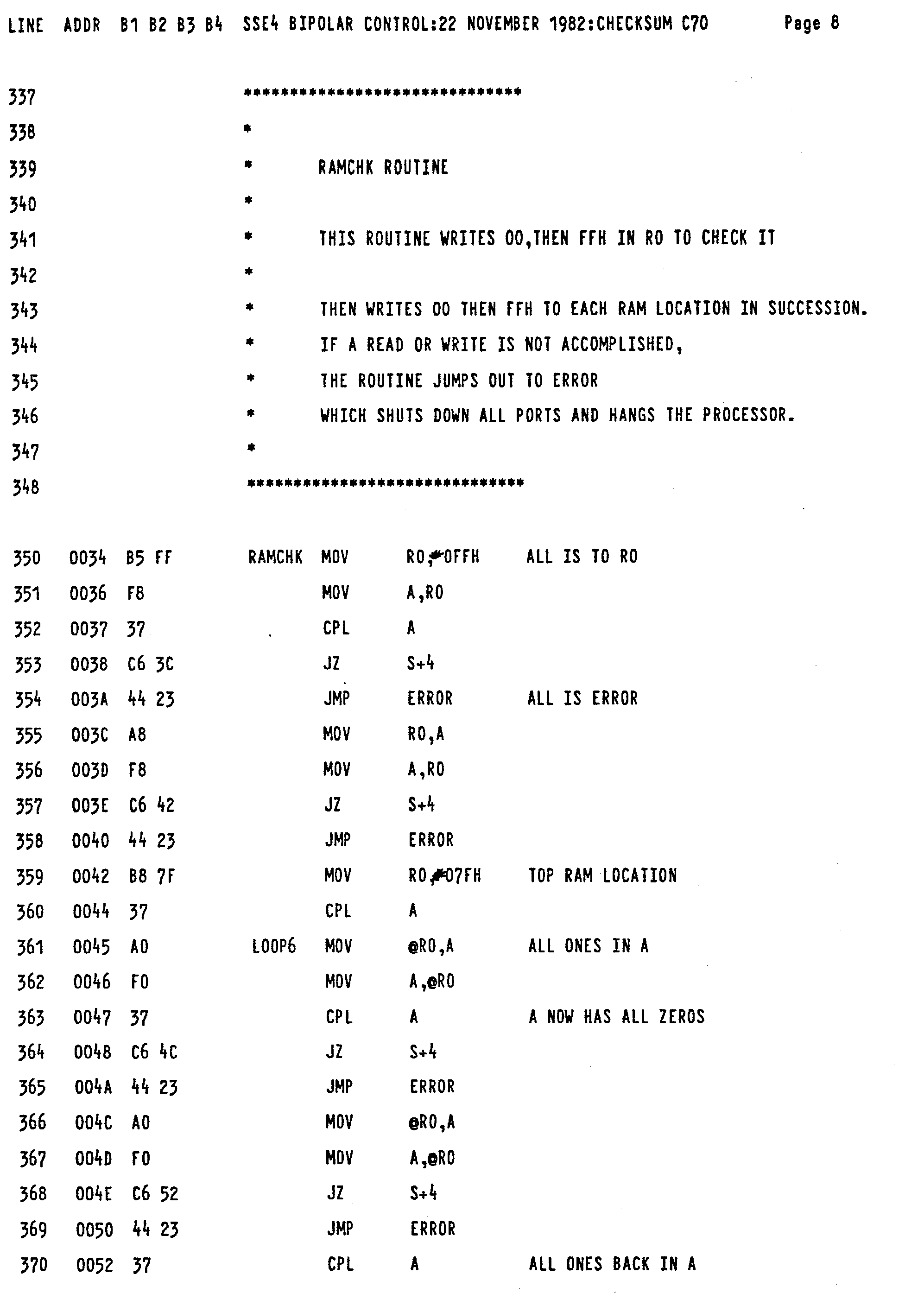
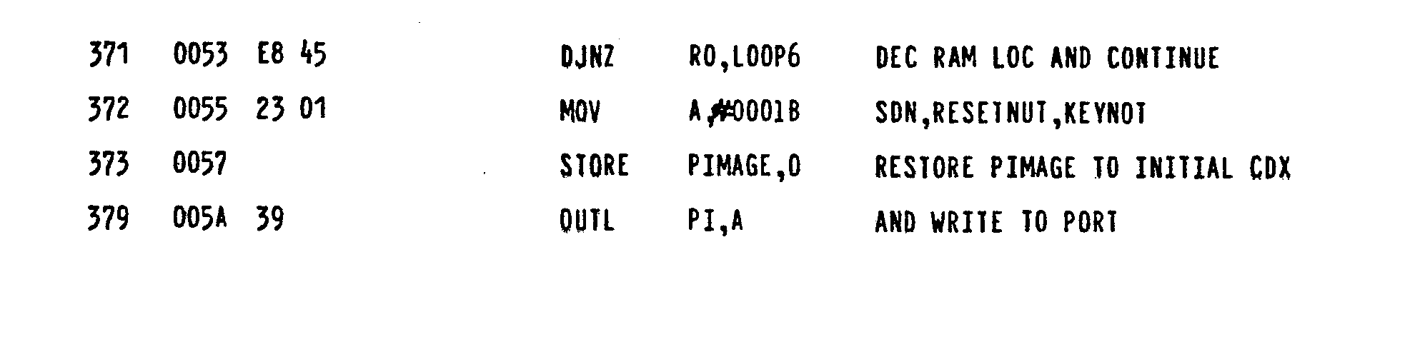
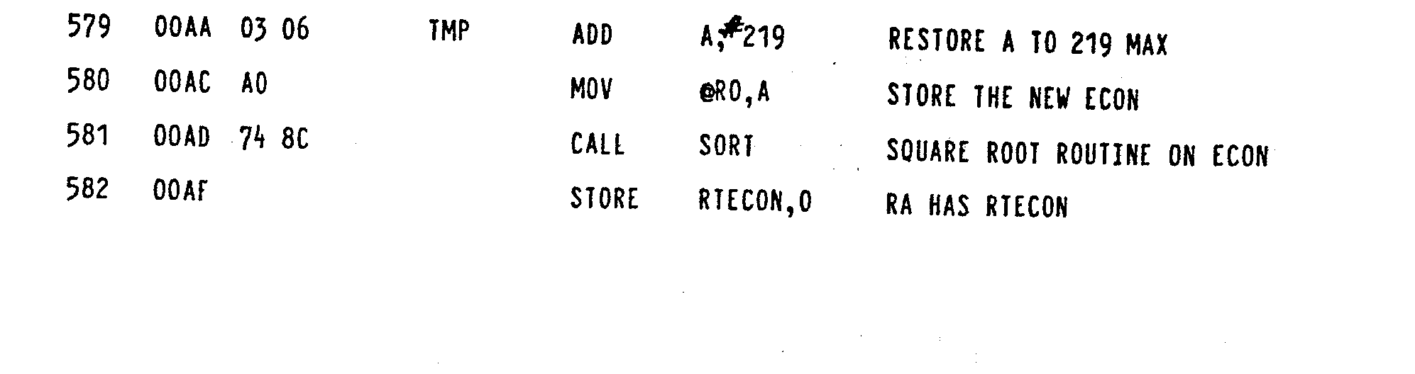
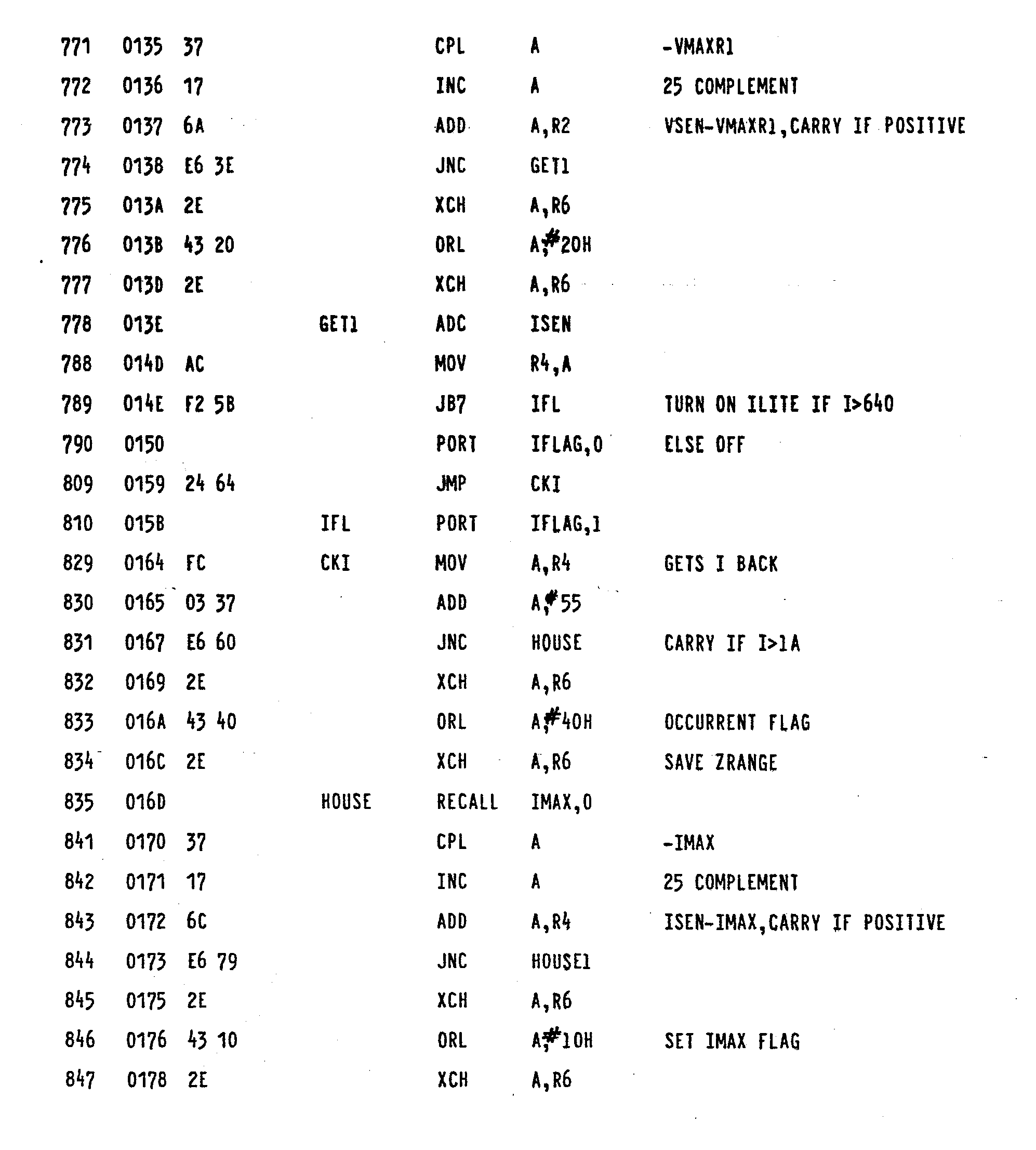
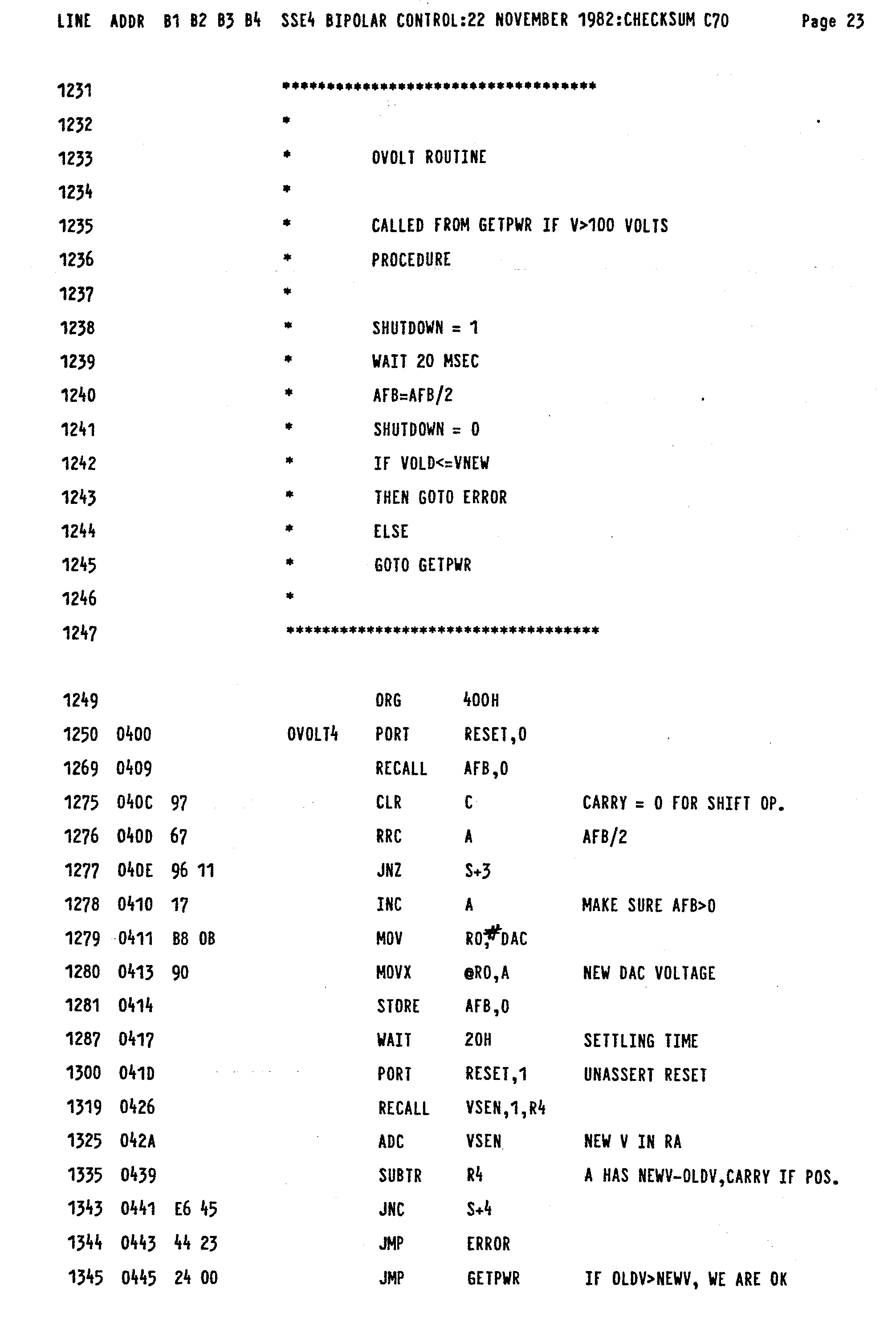
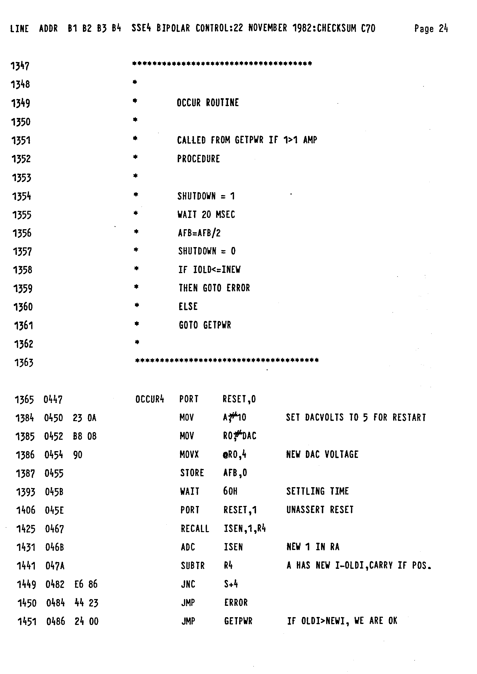
line 19 control voltage. Attached hereto as Appendix I is a program listing for the Figure 3 flowchart where the listing also includes various initialization, testing, and error programs. - Reference should now be made to Figures 4A and 4B which is a schematic diagram of switching
power supply 10, highefficiency RF generator 12, andcurrent sensors 14 of Figure 1. The switching power supply includes a standardswitching supply circuit 44 made by Silicon General. The remaining integrated circuits of the invention are also made by Silicon.General and other such companies. The switching power supply is of conventional configuration and includes a switchingtransistor 46 andinductor 47, and anoutput line 48 which applies regulated high voltage to output transistor 52 ofgenerator 12. The power supply voltage applied toline 48 originates fromterminal 50, this voltage typically being about 100 volts. The voltage atterminal 50 is regulated by switchingtransistor 46,inductor 47 andcapacitor 49 where, in particular, thelonger transistor 46 is switched off, the less the DC voltage applied toline 48 will be in magnitude. A voltage DC SENSE proportional to theline 48 voltage is applied toterminal 2 ofcircuit 44 via a voltagedivider comprising resistors line 19. - On-off pulses are applied to switching
transistor 46 fromcircuit 44 viatransistors 58 and.60. The repetition rate of these pulses is determined byresistor 62 andcapacitor 64 connected to the RT and CT terminals ofcircuit 44. The width of these pulses and thus the on/off time oftransistor 46 is a function of the difference between AFB and DC SENSE. Thus, in this manner the power supply voltage follows AFB as the impedance changes during a desiccation procedure. - The output power is delivered to the load via
lines output transformer 70. Thegenerator 12 is driven by a 750 KHz signal applied to terminal 72 where it is amplified and the applied to output transistor 52 which in turn drives prilrary winding 74 oftransformer 70. - The load current is sensed at
transformer 76 and converted to a voltage representative of the current by the conversion circuitry indicated at 78. This voltage is applied overline 17 as the ISEN signal of themicroprocessor 16. Furthermore, a voltage representative of the load voltage is derived from winding 80 oftransformer 70. This signal is converted bysignal conversion circuitry 82 to develop the load. voltage at VSEN online 19. - The values given for the resistors are in ohms while those for the capacitances are microfarads unless otherwise specified, these values being illustrative of the embodiment of the invention.
- It should be noted that overall operation of the present invention is such that a very small heat sink is needed to dissipate heat, thus, a 3-4 watt sink connected to transistor 52 is suitable, such a sink being very small in size. This follows from the fact that the amplifier is essentially matched to a 100 ohm load and only in a limited impedance range around that value is the maximum delivered to the load.
- With the load impedance substantially removed from 100 ohms, the power is reduced as discussed above and shown in Figure 2. There is no need to generate substantial wattage at impedances removed from the impedance to which the amplifier is matched. Accordingly, even at impedances removed from 100 ohms only a small amount of power is involved whereby the small heat sink mentioned above is suitable for these smaller powers.
- It is to be understood that the above-detailed description of an embodiment of the invention is provided by way of example only. Thus, for example, the above principles are also applicable to monopolar as well as bipolar electrosurgery.
-


Claims (24)
Priority Applications (1)
| Application Number | Priority Date | Filing Date | Title |
|---|---|---|---|
| AT84306208T ATE47959T1 (en) | 1983-09-13 | 1984-09-10 | GENERATOR FOR ELECTROSURGERY. |
Applications Claiming Priority (4)
| Application Number | Priority Date | Filing Date | Title |
|---|---|---|---|
| US53162183A | 1983-09-13 | 1983-09-13 | |
| US06/531,758 US4658819A (en) | 1983-09-13 | 1983-09-13 | Electrosurgical generator |
| US531621 | 1983-09-13 | ||
| US531758 | 1983-09-13 |
Publications (3)
| Publication Number | Publication Date |
|---|---|
| EP0136855A2 true EP0136855A2 (en) | 1985-04-10 |
| EP0136855A3 EP0136855A3 (en) | 1986-07-30 |
| EP0136855B1 EP0136855B1 (en) | 1989-11-15 |
Family
ID=27063586
Family Applications (1)
| Application Number | Title | Priority Date | Filing Date |
|---|---|---|---|
| EP19840306208 Expired EP0136855B1 (en) | 1983-09-13 | 1984-09-10 | Electrosurgical generator |
Country Status (3)
| Country | Link |
|---|---|
| EP (1) | EP0136855B1 (en) |
| AU (1) | AU555500B2 (en) |
| DE (1) | DE3480462D1 (en) |
Cited By (41)
| Publication number | Priority date | Publication date | Assignee | Title |
|---|---|---|---|---|
| US4712544A (en) * | 1986-02-12 | 1987-12-15 | Castle Company | Electrosurgical generator |
| US4727874A (en) * | 1984-09-10 | 1988-03-01 | C. R. Bard, Inc. | Electrosurgical generator with high-frequency pulse width modulated feedback power control |
| US4739759A (en) * | 1985-02-26 | 1988-04-26 | Concept, Inc. | Microprocessor controlled electrosurgical generator |
| GB2213381A (en) * | 1987-12-12 | 1989-08-16 | Univ Wales Medicine | Electro-surgical apparatus with body impedance monitoring |
| GB2216688A (en) * | 1988-03-28 | 1989-10-11 | Toshiba Kk | High frequency heating apparatus using microcomputer controlled inverter |
| DE3830193A1 (en) * | 1988-09-06 | 1990-03-15 | Hubmann Max | Method and electrical circuit for determining and/or limiting a high-frequency energy supplied with a catheter |
| EP0368532A2 (en) * | 1988-11-10 | 1990-05-16 | Smiths Industries Public Limited Company | Electrical power control apparatus and methods |
| WO1992021300A1 (en) * | 1991-06-06 | 1992-12-10 | Valleylab, Inc. | Electrosurgical and ultrasonic surgical system |
| WO1993003677A3 (en) * | 1991-08-12 | 1993-04-15 | Flachenecker Hildegard & Lf | Surgical high-frequency generator for cutting tissues |
| EP0566731A1 (en) * | 1991-11-08 | 1993-10-27 | Ep Technologies, Inc. | Radiofrequency ablation with phase sensitive power detection |
| EP0566726A1 (en) * | 1991-11-08 | 1993-10-27 | Ep Technologies, Inc. | Systems and methods for ablating tissue while monitoring tissue impedance |
| WO1993020770A2 (en) * | 1992-04-10 | 1993-10-28 | Cardiorhythm | Radiofrequency system for ablation of cardiac tissue |
| US5423810A (en) * | 1992-02-27 | 1995-06-13 | G2 Design Limited | Cauterising apparatus |
| US5540681A (en) * | 1992-04-10 | 1996-07-30 | Medtronic Cardiorhythm | Method and system for radiofrequency ablation of tissue |
| US5584830A (en) * | 1994-03-30 | 1996-12-17 | Medtronic Cardiorhythm | Method and system for radiofrequency ablation of cardiac tissue |
| US5688266A (en) * | 1991-11-08 | 1997-11-18 | Ep Technologies, Inc. | Electrode and associated systems using thermally insulated temperature sensing elements |
| US5743903A (en) * | 1991-11-08 | 1998-04-28 | Ep Technologies, Inc. | Cardiac ablation systems and methods using tissue temperature monitoring and control |
| DE4126607C2 (en) * | 1991-08-12 | 2003-10-09 | Storz Karl Gmbh & Co Kg | Arrangement for cutting biological tissue with high frequency current |
| WO2004045439A1 (en) * | 2002-11-19 | 2004-06-03 | Conmed Corporation | Electrosurgical generator with voltage and frequency regulated high-voltage current mode power supply |
| AU2011307254B2 (en) * | 2010-09-29 | 2016-02-04 | Alcon Inc. | Attenuated RF power for automated capsulorhexis |
| EP2293733B1 (en) * | 2008-05-13 | 2018-09-19 | Megadyne Medical Products, Inc. | System for performing electrosurgical procedures |
| US10263171B2 (en) | 2009-10-09 | 2019-04-16 | Ethicon Llc | Surgical generator for ultrasonic and electrosurgical devices |
| US10335614B2 (en) | 2008-08-06 | 2019-07-02 | Ethicon Llc | Devices and techniques for cutting and coagulating tissue |
| US10335183B2 (en) | 2012-06-29 | 2019-07-02 | Ethicon Llc | Feedback devices for surgical control systems |
| US10335182B2 (en) | 2012-06-29 | 2019-07-02 | Ethicon Llc | Surgical instruments with articulating shafts |
| US10342602B2 (en) | 2015-03-17 | 2019-07-09 | Ethicon Llc | Managing tissue treatment |
| US10349999B2 (en) | 2014-03-31 | 2019-07-16 | Ethicon Llc | Controlling impedance rise in electrosurgical medical devices |
| US10357303B2 (en) | 2015-06-30 | 2019-07-23 | Ethicon Llc | Translatable outer tube for sealing using shielded lap chole dissector |
| US10376305B2 (en) | 2016-08-05 | 2019-08-13 | Ethicon Llc | Methods and systems for advanced harmonic energy |
| US10398466B2 (en) | 2007-07-27 | 2019-09-03 | Ethicon Llc | Ultrasonic end effectors with increased active length |
| US10398497B2 (en) | 2012-06-29 | 2019-09-03 | Ethicon Llc | Lockout mechanism for use with robotic electrosurgical device |
| US10420579B2 (en) | 2007-07-31 | 2019-09-24 | Ethicon Llc | Surgical instruments |
| US10420580B2 (en) | 2016-08-25 | 2019-09-24 | Ethicon Llc | Ultrasonic transducer for surgical instrument |
| US10426507B2 (en) | 2007-07-31 | 2019-10-01 | Ethicon Llc | Ultrasonic surgical instruments |
| US10433866B2 (en) | 2007-11-30 | 2019-10-08 | Ethicon Llc | Ultrasonic surgical blades |
| US10433900B2 (en) | 2011-07-22 | 2019-10-08 | Ethicon Llc | Surgical instruments for tensioning tissue |
| US10441345B2 (en) | 2009-10-09 | 2019-10-15 | Ethicon Llc | Surgical generator for ultrasonic and electrosurgical devices |
| US10441308B2 (en) | 2007-11-30 | 2019-10-15 | Ethicon Llc | Ultrasonic surgical instrument blades |
| US10441310B2 (en) | 2012-06-29 | 2019-10-15 | Ethicon Llc | Surgical instruments with curved section |
| US10456193B2 (en) | 2016-05-03 | 2019-10-29 | Ethicon Llc | Medical device with a bilateral jaw configuration for nerve stimulation |
| US10463421B2 (en) | 2014-03-27 | 2019-11-05 | Ethicon Llc | Two stage trigger, clamp and cut bipolar vessel sealer |
Families Citing this family (115)
| Publication number | Priority date | Publication date | Assignee | Title |
|---|---|---|---|---|
| NO165661C (en) * | 1984-12-11 | 1991-03-20 | Valleylab Inc | ELECTRO-SURGICAL GENERATION SYSTEM. |
| CA2224975A1 (en) | 1995-06-23 | 1997-01-09 | Gyrus Medical Limited | An electrosurgical instrument |
| US6780180B1 (en) | 1995-06-23 | 2004-08-24 | Gyrus Medical Limited | Electrosurgical instrument |
| US6293942B1 (en) | 1995-06-23 | 2001-09-25 | Gyrus Medical Limited | Electrosurgical generator method |
| US6015406A (en) | 1996-01-09 | 2000-01-18 | Gyrus Medical Limited | Electrosurgical instrument |
| KR100463935B1 (en) | 1995-06-23 | 2005-05-16 | 자이러스 메디칼 리미티드 | An electrosurgical instrument |
| US6013076A (en) | 1996-01-09 | 2000-01-11 | Gyrus Medical Limited | Electrosurgical instrument |
| GB2314274A (en) | 1996-06-20 | 1997-12-24 | Gyrus Medical Ltd | Electrode construction for an electrosurgical instrument |
| GB9612993D0 (en) | 1996-06-20 | 1996-08-21 | Gyrus Medical Ltd | Electrosurgical instrument |
| US6565561B1 (en) | 1996-06-20 | 2003-05-20 | Cyrus Medical Limited | Electrosurgical instrument |
| GB9626512D0 (en) | 1996-12-20 | 1997-02-05 | Gyrus Medical Ltd | An improved electrosurgical generator and system |
| GB9807303D0 (en) | 1998-04-03 | 1998-06-03 | Gyrus Medical Ltd | An electrode assembly for an electrosurgical instrument |
| US7959626B2 (en) | 2001-04-26 | 2011-06-14 | Medtronic, Inc. | Transmural ablation systems and methods |
| US11229472B2 (en) | 2001-06-12 | 2022-01-25 | Cilag Gmbh International | Modular battery powered handheld surgical instrument with multiple magnetic position sensors |
| US8182501B2 (en) | 2004-02-27 | 2012-05-22 | Ethicon Endo-Surgery, Inc. | Ultrasonic surgical shears and method for sealing a blood vessel using same |
| JP5009159B2 (en) | 2004-10-08 | 2012-08-22 | エシコン・エンド−サージェリィ・インコーポレイテッド | Ultrasonic surgical instrument |
| US20070191713A1 (en) | 2005-10-14 | 2007-08-16 | Eichmann Stephen E | Ultrasonic device for cutting and coagulating |
| US7621930B2 (en) | 2006-01-20 | 2009-11-24 | Ethicon Endo-Surgery, Inc. | Ultrasound medical instrument having a medical ultrasonic blade |
| WO2008011575A1 (en) * | 2006-07-20 | 2008-01-24 | Medtronic, Inc. | Transmural ablation systems and methods |
| US8911460B2 (en) | 2007-03-22 | 2014-12-16 | Ethicon Endo-Surgery, Inc. | Ultrasonic surgical instruments |
| US8142461B2 (en) | 2007-03-22 | 2012-03-27 | Ethicon Endo-Surgery, Inc. | Surgical instruments |
| US8226675B2 (en) | 2007-03-22 | 2012-07-24 | Ethicon Endo-Surgery, Inc. | Surgical instruments |
| US8808319B2 (en) | 2007-07-27 | 2014-08-19 | Ethicon Endo-Surgery, Inc. | Surgical instruments |
| US8882791B2 (en) | 2007-07-27 | 2014-11-11 | Ethicon Endo-Surgery, Inc. | Ultrasonic surgical instruments |
| US9044261B2 (en) | 2007-07-31 | 2015-06-02 | Ethicon Endo-Surgery, Inc. | Temperature controlled ultrasonic surgical instruments |
| US8623027B2 (en) | 2007-10-05 | 2014-01-07 | Ethicon Endo-Surgery, Inc. | Ergonomic surgical instruments |
| US9700339B2 (en) | 2009-05-20 | 2017-07-11 | Ethicon Endo-Surgery, Inc. | Coupling arrangements and methods for attaching tools to ultrasonic surgical instruments |
| US8663220B2 (en) | 2009-07-15 | 2014-03-04 | Ethicon Endo-Surgery, Inc. | Ultrasonic surgical instruments |
| US11090104B2 (en) | 2009-10-09 | 2021-08-17 | Cilag Gmbh International | Surgical generator for ultrasonic and electrosurgical devices |
| USRE47996E1 (en) | 2009-10-09 | 2020-05-19 | Ethicon Llc | Surgical generator for ultrasonic and electrosurgical devices |
| US9168054B2 (en) | 2009-10-09 | 2015-10-27 | Ethicon Endo-Surgery, Inc. | Surgical generator for ultrasonic and electrosurgical devices |
| US8579928B2 (en) | 2010-02-11 | 2013-11-12 | Ethicon Endo-Surgery, Inc. | Outer sheath and blade arrangements for ultrasonic surgical instruments |
| US8486096B2 (en) | 2010-02-11 | 2013-07-16 | Ethicon Endo-Surgery, Inc. | Dual purpose surgical instrument for cutting and coagulating tissue |
| US8961547B2 (en) | 2010-02-11 | 2015-02-24 | Ethicon Endo-Surgery, Inc. | Ultrasonic surgical instruments with moving cutting implement |
| US8469981B2 (en) | 2010-02-11 | 2013-06-25 | Ethicon Endo-Surgery, Inc. | Rotatable cutting implement arrangements for ultrasonic surgical instruments |
| US8951272B2 (en) | 2010-02-11 | 2015-02-10 | Ethicon Endo-Surgery, Inc. | Seal arrangements for ultrasonically powered surgical instruments |
| GB2480498A (en) | 2010-05-21 | 2011-11-23 | Ethicon Endo Surgery Inc | Medical device comprising RF circuitry |
| US8795327B2 (en) | 2010-07-22 | 2014-08-05 | Ethicon Endo-Surgery, Inc. | Electrosurgical instrument with separate closure and cutting members |
| US9192431B2 (en) | 2010-07-23 | 2015-11-24 | Ethicon Endo-Surgery, Inc. | Electrosurgical cutting and sealing instrument |
| EP2811932B1 (en) | 2012-02-10 | 2019-06-26 | Ethicon LLC | Robotically controlled surgical instrument |
| US9724118B2 (en) | 2012-04-09 | 2017-08-08 | Ethicon Endo-Surgery, Llc | Techniques for cutting and coagulating tissue for ultrasonic surgical instruments |
| US9241731B2 (en) | 2012-04-09 | 2016-01-26 | Ethicon Endo-Surgery, Inc. | Rotatable electrical connection for ultrasonic surgical instruments |
| US9226766B2 (en) | 2012-04-09 | 2016-01-05 | Ethicon Endo-Surgery, Inc. | Serial communication protocol for medical device |
| US9237921B2 (en) | 2012-04-09 | 2016-01-19 | Ethicon Endo-Surgery, Inc. | Devices and techniques for cutting and coagulating tissue |
| US9439668B2 (en) | 2012-04-09 | 2016-09-13 | Ethicon Endo-Surgery, Llc | Switch arrangements for ultrasonic surgical instruments |
| US20140005705A1 (en) | 2012-06-29 | 2014-01-02 | Ethicon Endo-Surgery, Inc. | Surgical instruments with articulating shafts |
| US20140005702A1 (en) | 2012-06-29 | 2014-01-02 | Ethicon Endo-Surgery, Inc. | Ultrasonic surgical instruments with distally positioned transducers |
| US9226767B2 (en) | 2012-06-29 | 2016-01-05 | Ethicon Endo-Surgery, Inc. | Closed feedback control for electrosurgical device |
| US9351754B2 (en) | 2012-06-29 | 2016-05-31 | Ethicon Endo-Surgery, Llc | Ultrasonic surgical instruments with distally positioned jaw assemblies |
| US9820768B2 (en) | 2012-06-29 | 2017-11-21 | Ethicon Llc | Ultrasonic surgical instruments with control mechanisms |
| US9283045B2 (en) | 2012-06-29 | 2016-03-15 | Ethicon Endo-Surgery, Llc | Surgical instruments with fluid management system |
| BR112015007010B1 (en) | 2012-09-28 | 2022-05-31 | Ethicon Endo-Surgery, Inc | end actuator |
| US9095367B2 (en) | 2012-10-22 | 2015-08-04 | Ethicon Endo-Surgery, Inc. | Flexible harmonic waveguides/blades for surgical instruments |
| US10201365B2 (en) | 2012-10-22 | 2019-02-12 | Ethicon Llc | Surgeon feedback sensing and display methods |
| US20140135804A1 (en) | 2012-11-15 | 2014-05-15 | Ethicon Endo-Surgery, Inc. | Ultrasonic and electrosurgical devices |
| US10226273B2 (en) | 2013-03-14 | 2019-03-12 | Ethicon Llc | Mechanical fasteners for use with surgical energy devices |
| US9241728B2 (en) | 2013-03-15 | 2016-01-26 | Ethicon Endo-Surgery, Inc. | Surgical instrument with multiple clamping mechanisms |
| US9814514B2 (en) | 2013-09-13 | 2017-11-14 | Ethicon Llc | Electrosurgical (RF) medical instruments for cutting and coagulating tissue |
| US9265926B2 (en) | 2013-11-08 | 2016-02-23 | Ethicon Endo-Surgery, Llc | Electrosurgical devices |
| GB2521228A (en) | 2013-12-16 | 2015-06-17 | Ethicon Endo Surgery Inc | Medical device |
| GB2521229A (en) | 2013-12-16 | 2015-06-17 | Ethicon Endo Surgery Inc | Medical device |
| US9795436B2 (en) | 2014-01-07 | 2017-10-24 | Ethicon Llc | Harvesting energy from a surgical generator |
| US9554854B2 (en) | 2014-03-18 | 2017-01-31 | Ethicon Endo-Surgery, Llc | Detecting short circuits in electrosurgical medical devices |
| US10092310B2 (en) | 2014-03-27 | 2018-10-09 | Ethicon Llc | Electrosurgical devices |
| US9913680B2 (en) | 2014-04-15 | 2018-03-13 | Ethicon Llc | Software algorithms for electrosurgical instruments |
| US10285724B2 (en) | 2014-07-31 | 2019-05-14 | Ethicon Llc | Actuation mechanisms and load adjustment assemblies for surgical instruments |
| US10639092B2 (en) | 2014-12-08 | 2020-05-05 | Ethicon Llc | Electrode configurations for surgical instruments |
| US10245095B2 (en) | 2015-02-06 | 2019-04-02 | Ethicon Llc | Electrosurgical instrument with rotation and articulation mechanisms |
| US10321950B2 (en) | 2015-03-17 | 2019-06-18 | Ethicon Llc | Managing tissue treatment |
| US10595929B2 (en) | 2015-03-24 | 2020-03-24 | Ethicon Llc | Surgical instruments with firing system overload protection mechanisms |
| US10034684B2 (en) | 2015-06-15 | 2018-07-31 | Ethicon Llc | Apparatus and method for dissecting and coagulating tissue |
| US11020140B2 (en) | 2015-06-17 | 2021-06-01 | Cilag Gmbh International | Ultrasonic surgical blade for use with ultrasonic surgical instruments |
| US11141213B2 (en) | 2015-06-30 | 2021-10-12 | Cilag Gmbh International | Surgical instrument with user adaptable techniques |
| US11129669B2 (en) | 2015-06-30 | 2021-09-28 | Cilag Gmbh International | Surgical system with user adaptable techniques based on tissue type |
| US10898256B2 (en) | 2015-06-30 | 2021-01-26 | Ethicon Llc | Surgical system with user adaptable techniques based on tissue impedance |
| US10034704B2 (en) | 2015-06-30 | 2018-07-31 | Ethicon Llc | Surgical instrument with user adaptable algorithms |
| US11051873B2 (en) | 2015-06-30 | 2021-07-06 | Cilag Gmbh International | Surgical system with user adaptable techniques employing multiple energy modalities based on tissue parameters |
| US10154852B2 (en) | 2015-07-01 | 2018-12-18 | Ethicon Llc | Ultrasonic surgical blade with improved cutting and coagulation features |
| US11033322B2 (en) | 2015-09-30 | 2021-06-15 | Ethicon Llc | Circuit topologies for combined generator |
| US10595930B2 (en) | 2015-10-16 | 2020-03-24 | Ethicon Llc | Electrode wiping surgical device |
| US10179022B2 (en) | 2015-12-30 | 2019-01-15 | Ethicon Llc | Jaw position impedance limiter for electrosurgical instrument |
| US10575892B2 (en) | 2015-12-31 | 2020-03-03 | Ethicon Llc | Adapter for electrical surgical instruments |
| US10716615B2 (en) | 2016-01-15 | 2020-07-21 | Ethicon Llc | Modular battery powered handheld surgical instrument with curved end effectors having asymmetric engagement between jaw and blade |
| US11129670B2 (en) | 2016-01-15 | 2021-09-28 | Cilag Gmbh International | Modular battery powered handheld surgical instrument with selective application of energy based on button displacement, intensity, or local tissue characterization |
| US11051840B2 (en) | 2016-01-15 | 2021-07-06 | Ethicon Llc | Modular battery powered handheld surgical instrument with reusable asymmetric handle housing |
| US11229471B2 (en) | 2016-01-15 | 2022-01-25 | Cilag Gmbh International | Modular battery powered handheld surgical instrument with selective application of energy based on tissue characterization |
| US10555769B2 (en) | 2016-02-22 | 2020-02-11 | Ethicon Llc | Flexible circuits for electrosurgical instrument |
| US10485607B2 (en) | 2016-04-29 | 2019-11-26 | Ethicon Llc | Jaw structure with distal closure for electrosurgical instruments |
| US10702329B2 (en) | 2016-04-29 | 2020-07-07 | Ethicon Llc | Jaw structure with distal post for electrosurgical instruments |
| US10646269B2 (en) | 2016-04-29 | 2020-05-12 | Ethicon Llc | Non-linear jaw gap for electrosurgical instruments |
| US10245064B2 (en) | 2016-07-12 | 2019-04-02 | Ethicon Llc | Ultrasonic surgical instrument with piezoelectric central lumen transducer |
| US10893883B2 (en) | 2016-07-13 | 2021-01-19 | Ethicon Llc | Ultrasonic assembly for use with ultrasonic surgical instruments |
| US10842522B2 (en) | 2016-07-15 | 2020-11-24 | Ethicon Llc | Ultrasonic surgical instruments having offset blades |
| US10285723B2 (en) | 2016-08-09 | 2019-05-14 | Ethicon Llc | Ultrasonic surgical blade with improved heel portion |
| USD847990S1 (en) | 2016-08-16 | 2019-05-07 | Ethicon Llc | Surgical instrument |
| US10952759B2 (en) | 2016-08-25 | 2021-03-23 | Ethicon Llc | Tissue loading of a surgical instrument |
| US10603064B2 (en) | 2016-11-28 | 2020-03-31 | Ethicon Llc | Ultrasonic transducer |
| US11266430B2 (en) | 2016-11-29 | 2022-03-08 | Cilag Gmbh International | End effector control and calibration |
| US10820920B2 (en) | 2017-07-05 | 2020-11-03 | Ethicon Llc | Reusable ultrasonic medical devices and methods of their use |
| US11812957B2 (en) | 2019-12-30 | 2023-11-14 | Cilag Gmbh International | Surgical instrument comprising a signal interference resolution system |
| US11786291B2 (en) | 2019-12-30 | 2023-10-17 | Cilag Gmbh International | Deflectable support of RF energy electrode with respect to opposing ultrasonic blade |
| US11684412B2 (en) | 2019-12-30 | 2023-06-27 | Cilag Gmbh International | Surgical instrument with rotatable and articulatable surgical end effector |
| US11744636B2 (en) | 2019-12-30 | 2023-09-05 | Cilag Gmbh International | Electrosurgical systems with integrated and external power sources |
| US11786294B2 (en) | 2019-12-30 | 2023-10-17 | Cilag Gmbh International | Control program for modular combination energy device |
| US20210196361A1 (en) | 2019-12-30 | 2021-07-01 | Ethicon Llc | Electrosurgical instrument with monopolar and bipolar energy capabilities |
| US11911063B2 (en) | 2019-12-30 | 2024-02-27 | Cilag Gmbh International | Techniques for detecting ultrasonic blade to electrode contact and reducing power to ultrasonic blade |
| US11696776B2 (en) | 2019-12-30 | 2023-07-11 | Cilag Gmbh International | Articulatable surgical instrument |
| US11937863B2 (en) | 2019-12-30 | 2024-03-26 | Cilag Gmbh International | Deflectable electrode with variable compression bias along the length of the deflectable electrode |
| US11950797B2 (en) | 2019-12-30 | 2024-04-09 | Cilag Gmbh International | Deflectable electrode with higher distal bias relative to proximal bias |
| US11452525B2 (en) | 2019-12-30 | 2022-09-27 | Cilag Gmbh International | Surgical instrument comprising an adjustment system |
| US11779387B2 (en) | 2019-12-30 | 2023-10-10 | Cilag Gmbh International | Clamp arm jaw to minimize tissue sticking and improve tissue control |
| US11660089B2 (en) | 2019-12-30 | 2023-05-30 | Cilag Gmbh International | Surgical instrument comprising a sensing system |
| US11937866B2 (en) | 2019-12-30 | 2024-03-26 | Cilag Gmbh International | Method for an electrosurgical procedure |
| US11944366B2 (en) | 2019-12-30 | 2024-04-02 | Cilag Gmbh International | Asymmetric segmented ultrasonic support pad for cooperative engagement with a movable RF electrode |
| US11779329B2 (en) | 2019-12-30 | 2023-10-10 | Cilag Gmbh International | Surgical instrument comprising a flex circuit including a sensor system |
Citations (5)
| Publication number | Priority date | Publication date | Assignee | Title |
|---|---|---|---|---|
| US1995526A (en) * | 1932-09-27 | 1935-03-26 | Wappler Frederick Charles | Electrosurgical apparatus |
| DE2803017A1 (en) * | 1977-01-21 | 1978-07-27 | Minnesota Mining & Mfg | ELECTROSURGICAL UNIT |
| FR2474307A1 (en) * | 1979-12-11 | 1981-07-31 | Lamidey Gilles | Surgical coagulating clamp supply controller - measures electrical conductivity of tissues between jaws of clamp and produces signal to stop supply when value reaches predetermined level |
| DE3120102A1 (en) * | 1981-05-20 | 1982-12-09 | F.L. Fischer GmbH & Co, 7800 Freiburg | ARRANGEMENT FOR HIGH-FREQUENCY COAGULATION OF EGG WHITE FOR SURGICAL PURPOSES |
| EP0126814A1 (en) * | 1983-05-24 | 1984-12-05 | Sien-Shih Chang | Electro-surgical unit control apparatus |
-
1984
- 1984-09-10 EP EP19840306208 patent/EP0136855B1/en not_active Expired
- 1984-09-10 DE DE8484306208T patent/DE3480462D1/en not_active Expired
- 1984-09-12 AU AU32957/84A patent/AU555500B2/en not_active Expired
Patent Citations (5)
| Publication number | Priority date | Publication date | Assignee | Title |
|---|---|---|---|---|
| US1995526A (en) * | 1932-09-27 | 1935-03-26 | Wappler Frederick Charles | Electrosurgical apparatus |
| DE2803017A1 (en) * | 1977-01-21 | 1978-07-27 | Minnesota Mining & Mfg | ELECTROSURGICAL UNIT |
| FR2474307A1 (en) * | 1979-12-11 | 1981-07-31 | Lamidey Gilles | Surgical coagulating clamp supply controller - measures electrical conductivity of tissues between jaws of clamp and produces signal to stop supply when value reaches predetermined level |
| DE3120102A1 (en) * | 1981-05-20 | 1982-12-09 | F.L. Fischer GmbH & Co, 7800 Freiburg | ARRANGEMENT FOR HIGH-FREQUENCY COAGULATION OF EGG WHITE FOR SURGICAL PURPOSES |
| EP0126814A1 (en) * | 1983-05-24 | 1984-12-05 | Sien-Shih Chang | Electro-surgical unit control apparatus |
Cited By (59)
| Publication number | Priority date | Publication date | Assignee | Title |
|---|---|---|---|---|
| US4727874A (en) * | 1984-09-10 | 1988-03-01 | C. R. Bard, Inc. | Electrosurgical generator with high-frequency pulse width modulated feedback power control |
| US4739759A (en) * | 1985-02-26 | 1988-04-26 | Concept, Inc. | Microprocessor controlled electrosurgical generator |
| US4712544A (en) * | 1986-02-12 | 1987-12-15 | Castle Company | Electrosurgical generator |
| GB2213381A (en) * | 1987-12-12 | 1989-08-16 | Univ Wales Medicine | Electro-surgical apparatus with body impedance monitoring |
| GB2213381B (en) * | 1987-12-12 | 1992-06-03 | Univ Wales Medicine | Surgical diathermy instruments |
| GB2216688B (en) * | 1988-03-28 | 1992-04-22 | Toshiba Kk | High frequency heating apparatus using microcomputer controlled inverter |
| GB2216688A (en) * | 1988-03-28 | 1989-10-11 | Toshiba Kk | High frequency heating apparatus using microcomputer controlled inverter |
| DE3830193A1 (en) * | 1988-09-06 | 1990-03-15 | Hubmann Max | Method and electrical circuit for determining and/or limiting a high-frequency energy supplied with a catheter |
| US4961047A (en) * | 1988-11-10 | 1990-10-02 | Smiths Industries Public Limited Company | Electrical power control apparatus and methods |
| EP0368532A3 (en) * | 1988-11-10 | 1990-11-22 | Smiths Industries Public Limited Company | Electrical power control apparatus and methods |
| GB2225656A (en) * | 1988-11-10 | 1990-06-06 | Smiths Industries Plc | Electric power control |
| GB2225656B (en) * | 1988-11-10 | 1992-11-11 | Smiths Industries Plc | Electrical power control apparatus and methods |
| EP0368532A2 (en) * | 1988-11-10 | 1990-05-16 | Smiths Industries Public Limited Company | Electrical power control apparatus and methods |
| AU660467B2 (en) * | 1991-06-06 | 1995-06-29 | Michael S. Klicek | Electrosurgical and ultrasonic surgical system |
| WO1992021300A1 (en) * | 1991-06-06 | 1992-12-10 | Valleylab, Inc. | Electrosurgical and ultrasonic surgical system |
| WO1993003677A3 (en) * | 1991-08-12 | 1993-04-15 | Flachenecker Hildegard & Lf | Surgical high-frequency generator for cutting tissues |
| DE4126607C2 (en) * | 1991-08-12 | 2003-10-09 | Storz Karl Gmbh & Co Kg | Arrangement for cutting biological tissue with high frequency current |
| US5743903A (en) * | 1991-11-08 | 1998-04-28 | Ep Technologies, Inc. | Cardiac ablation systems and methods using tissue temperature monitoring and control |
| US5688266A (en) * | 1991-11-08 | 1997-11-18 | Ep Technologies, Inc. | Electrode and associated systems using thermally insulated temperature sensing elements |
| EP0566726A4 (en) * | 1991-11-08 | 1994-03-16 | Ep Technologies, Inc. | |
| EP0566731A4 (en) * | 1991-11-08 | 1995-02-22 | Ep Technologies | Radiofrequency ablation with phase sensitive power detection. |
| EP0566731A1 (en) * | 1991-11-08 | 1993-10-27 | Ep Technologies, Inc. | Radiofrequency ablation with phase sensitive power detection |
| US5897552A (en) * | 1991-11-08 | 1999-04-27 | Ep Technologies, Inc. | Electrode and associated systems using thermally insulated temperature sensing elements |
| EP0566726A1 (en) * | 1991-11-08 | 1993-10-27 | Ep Technologies, Inc. | Systems and methods for ablating tissue while monitoring tissue impedance |
| US5722975A (en) * | 1991-11-08 | 1998-03-03 | E.P. Technologies Inc. | Systems for radiofrequency ablation with phase sensitive power detection and control |
| US5423810A (en) * | 1992-02-27 | 1995-06-13 | G2 Design Limited | Cauterising apparatus |
| US5573533A (en) * | 1992-04-10 | 1996-11-12 | Medtronic Cardiorhythm | Method and system for radiofrequency ablation of cardiac tissue |
| WO1993020770A3 (en) * | 1992-04-10 | 1993-12-23 | Cardiorhythm | Radiofrequency system for ablation of cardiac tissue |
| US5540681A (en) * | 1992-04-10 | 1996-07-30 | Medtronic Cardiorhythm | Method and system for radiofrequency ablation of tissue |
| WO1993020770A2 (en) * | 1992-04-10 | 1993-10-28 | Cardiorhythm | Radiofrequency system for ablation of cardiac tissue |
| US5584830A (en) * | 1994-03-30 | 1996-12-17 | Medtronic Cardiorhythm | Method and system for radiofrequency ablation of cardiac tissue |
| WO2004045439A1 (en) * | 2002-11-19 | 2004-06-03 | Conmed Corporation | Electrosurgical generator with voltage and frequency regulated high-voltage current mode power supply |
| US6939347B2 (en) | 2002-11-19 | 2005-09-06 | Conmed Corporation | Electrosurgical generator and method with voltage and frequency regulated high-voltage current mode power supply |
| US10398466B2 (en) | 2007-07-27 | 2019-09-03 | Ethicon Llc | Ultrasonic end effectors with increased active length |
| US10420579B2 (en) | 2007-07-31 | 2019-09-24 | Ethicon Llc | Surgical instruments |
| US10426507B2 (en) | 2007-07-31 | 2019-10-01 | Ethicon Llc | Ultrasonic surgical instruments |
| US10463887B2 (en) | 2007-11-30 | 2019-11-05 | Ethicon Llc | Ultrasonic surgical blades |
| US10433865B2 (en) | 2007-11-30 | 2019-10-08 | Ethicon Llc | Ultrasonic surgical blades |
| US10441308B2 (en) | 2007-11-30 | 2019-10-15 | Ethicon Llc | Ultrasonic surgical instrument blades |
| US10433866B2 (en) | 2007-11-30 | 2019-10-08 | Ethicon Llc | Ultrasonic surgical blades |
| EP3424456A1 (en) * | 2008-05-13 | 2019-01-09 | Megadyne Medical Products, Inc. | System and device for performing electrosurgical procedures |
| EP2293733B1 (en) * | 2008-05-13 | 2018-09-19 | Megadyne Medical Products, Inc. | System for performing electrosurgical procedures |
| US10335614B2 (en) | 2008-08-06 | 2019-07-02 | Ethicon Llc | Devices and techniques for cutting and coagulating tissue |
| US10263171B2 (en) | 2009-10-09 | 2019-04-16 | Ethicon Llc | Surgical generator for ultrasonic and electrosurgical devices |
| US10441345B2 (en) | 2009-10-09 | 2019-10-15 | Ethicon Llc | Surgical generator for ultrasonic and electrosurgical devices |
| US10265117B2 (en) | 2009-10-09 | 2019-04-23 | Ethicon Llc | Surgical generator method for controlling and ultrasonic transducer waveform for ultrasonic and electrosurgical devices |
| AU2011307254B2 (en) * | 2010-09-29 | 2016-02-04 | Alcon Inc. | Attenuated RF power for automated capsulorhexis |
| US10433900B2 (en) | 2011-07-22 | 2019-10-08 | Ethicon Llc | Surgical instruments for tensioning tissue |
| US10441310B2 (en) | 2012-06-29 | 2019-10-15 | Ethicon Llc | Surgical instruments with curved section |
| US10335182B2 (en) | 2012-06-29 | 2019-07-02 | Ethicon Llc | Surgical instruments with articulating shafts |
| US10335183B2 (en) | 2012-06-29 | 2019-07-02 | Ethicon Llc | Feedback devices for surgical control systems |
| US10398497B2 (en) | 2012-06-29 | 2019-09-03 | Ethicon Llc | Lockout mechanism for use with robotic electrosurgical device |
| US10463421B2 (en) | 2014-03-27 | 2019-11-05 | Ethicon Llc | Two stage trigger, clamp and cut bipolar vessel sealer |
| US10349999B2 (en) | 2014-03-31 | 2019-07-16 | Ethicon Llc | Controlling impedance rise in electrosurgical medical devices |
| US10342602B2 (en) | 2015-03-17 | 2019-07-09 | Ethicon Llc | Managing tissue treatment |
| US10357303B2 (en) | 2015-06-30 | 2019-07-23 | Ethicon Llc | Translatable outer tube for sealing using shielded lap chole dissector |
| US10456193B2 (en) | 2016-05-03 | 2019-10-29 | Ethicon Llc | Medical device with a bilateral jaw configuration for nerve stimulation |
| US10376305B2 (en) | 2016-08-05 | 2019-08-13 | Ethicon Llc | Methods and systems for advanced harmonic energy |
| US10420580B2 (en) | 2016-08-25 | 2019-09-24 | Ethicon Llc | Ultrasonic transducer for surgical instrument |
Also Published As
| Publication number | Publication date |
|---|---|
| DE3480462D1 (en) | 1989-12-21 |
| EP0136855A3 (en) | 1986-07-30 |
| AU555500B2 (en) | 1986-09-25 |
| AU3295784A (en) | 1985-03-21 |
| EP0136855B1 (en) | 1989-11-15 |
Similar Documents
| Publication | Publication Date | Title |
|---|---|---|
| EP0136855B1 (en) | Electrosurgical generator | |
| US4658819A (en) | Electrosurgical generator | |
| US5772659A (en) | Electrosurgical generator power control circuit and method | |
| EP2022427B1 (en) | System for return electrode monitoring | |
| EP2160993B1 (en) | Electrosurgical apparatus with high speed energy recovery | |
| EP0870473B1 (en) | Electrosurgical generator with adaptive power control | |
| US8430873B2 (en) | System and method for return electrode monitoring | |
| JP5684979B2 (en) | Electrosurgical device with fast energy recovery | |
| JP5209257B2 (en) | System and method for return electrode monitoring | |
| US5087257A (en) | Apparatus for monitoring the application of neutral electrodes on a patient undergoing high frequency electro-surgery | |
| US20020165530A1 (en) | Electrosurgical device for treating body tissue with high-frequency power | |
| US20070073284A1 (en) | Multiple RF return pad contact detection system | |
| JPH10507393A (en) | Control system for neurosurgical electrosurgical devices | |
| JPH0451176B2 (en) | ||
| JP2000157556A (en) | Electric operation device | |
| JP2001198138A (en) | Electric surgical instrument |
Legal Events
| Date | Code | Title | Description |
|---|---|---|---|
| PUAI | Public reference made under article 153(3) epc to a published international application that has entered the european phase |
Free format text: ORIGINAL CODE: 0009012 |
|
| AK | Designated contracting states |
Designated state(s): AT BE CH DE FR GB IT LI LU NL SE |
|
| PUAL | Search report despatched |
Free format text: ORIGINAL CODE: 0009013 |
|
| AK | Designated contracting states |
Kind code of ref document: A3 Designated state(s): AT BE CH DE FR GB IT LI LU NL SE |
|
| 17P | Request for examination filed |
Effective date: 19861111 |
|
| 17Q | First examination report despatched |
Effective date: 19880530 |
|
| GRAA | (expected) grant |
Free format text: ORIGINAL CODE: 0009210 |
|
| AK | Designated contracting states |
Kind code of ref document: B1 Designated state(s): AT BE CH DE FR GB IT LI LU NL SE |
|
| REF | Corresponds to: |
Ref document number: 47959 Country of ref document: AT Date of ref document: 19891215 Kind code of ref document: T |
|
| ET | Fr: translation filed | ||
| REF | Corresponds to: |
Ref document number: 3480462 Country of ref document: DE Date of ref document: 19891221 |
|
| ITF | It: translation for a ep patent filed |
Owner name: MODIANO & ASSOCIATI S.R.L. |
|
| PLBE | No opposition filed within time limit |
Free format text: ORIGINAL CODE: 0009261 |
|
| STAA | Information on the status of an ep patent application or granted ep patent |
Free format text: STATUS: NO OPPOSITION FILED WITHIN TIME LIMIT |
|
| 26N | No opposition filed | ||
| ITTA | It: last paid annual fee | ||
| EPTA | Lu: last paid annual fee | ||
| EAL | Se: european patent in force in sweden |
Ref document number: 84306208.4 |
|
| PGFP | Annual fee paid to national office [announced via postgrant information from national office to epo] |
Ref country code: SE Payment date: 19970606 Year of fee payment: 14 |
|
| PGFP | Annual fee paid to national office [announced via postgrant information from national office to epo] |
Ref country code: BE Payment date: 19970627 Year of fee payment: 14 |
|
| PGFP | Annual fee paid to national office [announced via postgrant information from national office to epo] |
Ref country code: AT Payment date: 19970709 Year of fee payment: 14 |
|
| PGFP | Annual fee paid to national office [announced via postgrant information from national office to epo] |
Ref country code: CH Payment date: 19970813 Year of fee payment: 14 |
|
| PGFP | Annual fee paid to national office [announced via postgrant information from national office to epo] |
Ref country code: LU Payment date: 19971007 Year of fee payment: 14 |
|
| PG25 | Lapsed in a contracting state [announced via postgrant information from national office to epo] |
Ref country code: LU Free format text: LAPSE BECAUSE OF NON-PAYMENT OF DUE FEES Effective date: 19980910 Ref country code: AT Free format text: LAPSE BECAUSE OF NON-PAYMENT OF DUE FEES Effective date: 19980910 |
|
| PG25 | Lapsed in a contracting state [announced via postgrant information from national office to epo] |
Ref country code: SE Free format text: LAPSE BECAUSE OF NON-PAYMENT OF DUE FEES Effective date: 19980911 |
|
| PG25 | Lapsed in a contracting state [announced via postgrant information from national office to epo] |
Ref country code: LI Free format text: LAPSE BECAUSE OF NON-PAYMENT OF DUE FEES Effective date: 19980930 Ref country code: CH Free format text: LAPSE BECAUSE OF NON-PAYMENT OF DUE FEES Effective date: 19980930 Ref country code: BE Free format text: LAPSE BECAUSE OF NON-PAYMENT OF DUE FEES Effective date: 19980930 |
|
| BERE | Be: lapsed |
Owner name: VALLEYLAB INC. Effective date: 19980930 |
|
| REG | Reference to a national code |
Ref country code: CH Ref legal event code: PL |
|
| EUG | Se: european patent has lapsed |
Ref document number: 84306208.4 |
|
| REG | Reference to a national code |
Ref country code: GB Ref legal event code: 732E |
|
| NLS | Nl: assignments of ep-patents |
Owner name: SHERWOOD SERVICES AG |
|
| REG | Reference to a national code |
Ref country code: GB Ref legal event code: IF02 |
|
| REG | Reference to a national code |
Ref country code: FR Ref legal event code: TP |
|
| PGFP | Annual fee paid to national office [announced via postgrant information from national office to epo] |
Ref country code: NL Payment date: 20030825 Year of fee payment: 20 |
|
| PGFP | Annual fee paid to national office [announced via postgrant information from national office to epo] |
Ref country code: GB Payment date: 20030902 Year of fee payment: 20 |
|
| PGFP | Annual fee paid to national office [announced via postgrant information from national office to epo] |
Ref country code: FR Payment date: 20030918 Year of fee payment: 20 |
|
| PGFP | Annual fee paid to national office [announced via postgrant information from national office to epo] |
Ref country code: DE Payment date: 20031031 Year of fee payment: 20 |
|
| PG25 | Lapsed in a contracting state [announced via postgrant information from national office to epo] |
Ref country code: GB Free format text: LAPSE BECAUSE OF EXPIRATION OF PROTECTION Effective date: 20040909 |
|
| PG25 | Lapsed in a contracting state [announced via postgrant information from national office to epo] |
Ref country code: NL Free format text: LAPSE BECAUSE OF EXPIRATION OF PROTECTION Effective date: 20040910 |
|
| REG | Reference to a national code |
Ref country code: GB Ref legal event code: PE20 |
|
| NLV7 | Nl: ceased due to reaching the maximum lifetime of a patent |
Effective date: 20040910 |