EP0130715A2 - Sorting machine - Google Patents
Sorting machine Download PDFInfo
- Publication number
- EP0130715A2 EP0130715A2 EP84303997A EP84303997A EP0130715A2 EP 0130715 A2 EP0130715 A2 EP 0130715A2 EP 84303997 A EP84303997 A EP 84303997A EP 84303997 A EP84303997 A EP 84303997A EP 0130715 A2 EP0130715 A2 EP 0130715A2
- Authority
- EP
- European Patent Office
- Prior art keywords
- viewing
- objects
- light
- light source
- sorting machine
- Prior art date
- Legal status (The legal status is an assumption and is not a legal conclusion. Google has not performed a legal analysis and makes no representation as to the accuracy of the status listed.)
- Granted
Links
Images


Classifications
-
- B—PERFORMING OPERATIONS; TRANSPORTING
- B07—SEPARATING SOLIDS FROM SOLIDS; SORTING
- B07C—POSTAL SORTING; SORTING INDIVIDUAL ARTICLES, OR BULK MATERIAL FIT TO BE SORTED PIECE-MEAL, e.g. BY PICKING
- B07C5/00—Sorting according to a characteristic or feature of the articles or material being sorted, e.g. by control effected by devices which detect or measure such characteristic or feature; Sorting by manually actuated devices, e.g. switches
- B07C5/34—Sorting according to other particular properties
- B07C5/342—Sorting according to other particular properties according to optical properties, e.g. colour
- B07C5/3425—Sorting according to other particular properties according to optical properties, e.g. colour of granular material, e.g. ore particles, grain
-
- B—PERFORMING OPERATIONS; TRANSPORTING
- B07—SEPARATING SOLIDS FROM SOLIDS; SORTING
- B07C—POSTAL SORTING; SORTING INDIVIDUAL ARTICLES, OR BULK MATERIAL FIT TO BE SORTED PIECE-MEAL, e.g. BY PICKING
- B07C5/00—Sorting according to a characteristic or feature of the articles or material being sorted, e.g. by control effected by devices which detect or measure such characteristic or feature; Sorting by manually actuated devices, e.g. switches
- B07C5/36—Sorting apparatus characterised by the means used for distribution
- B07C5/363—Sorting apparatus characterised by the means used for distribution by means of air
- B07C5/365—Sorting apparatus characterised by the means used for distribution by means of air using a single separation means
- B07C5/366—Sorting apparatus characterised by the means used for distribution by means of air using a single separation means during free fall of the articles
Definitions
- the present invention concerns sorting machines and although the invention is not so restricted it more particularly concerns sorting machines which observe the light reflected from the surface of objects in order to effect sorting in dependence upon the colour or reflectivity of the objects.
- Such machines are commonly used in the processing of agricultural produce, such as rice, coffee and beans, and also in the purification of minerals, either in the form of streams of fine particles or in the form of lumps of ore.
- a sorting machine is often arranged to view an object simultaneously through several lenses. The reason for this is that a small discolouration, or defect, may only be visible over a restricted range of viewing angles.
- Common configurations are:-
- An advantage of viewing simultaneously from several different directions is that the signals from each viewing direction, which determine whether or not an ejector is to be operated so as to remove an undesired object from a stream of objects being viewed, may simply be combined.
- the ejector is spaced from the viewing area and the signals from the latter are therefore transmitted to the ejector after a delay which corresponds to the time taken for the undesired object to travel from the viewing area to the ejector.
- each signal from the viewing area needs to be delayed to the same extent before being transmitted to the ejector.
- the diffusely reflected light which it is desirable that a viewing system receive, is scattered at the surface of the object.
- This diffusely reflected light contains the information concerning reflectivity and colour upon which the operation of the sorting machine is based.
- the object to be sorted e.g. a coffee bean
- specular reflections in addition to the diffusely reflected light. Specular reflections from the front of the object being viewed are not a great problem since they do not normally form a very high proportion of the light being viewed.
- specular reflections are a particular problem when illumination from the rear of the object strikes the edge of the object at glancing incidence.
- Such specular reflections at glancing incidence, may constitute most (e.g. 90%) of the light being viewed and since they are often strong in intensity and have different colour characteristics from the light which is reflected diffusely from the surface of the object, they may seriously affect the accuracy of the sorting action of the machine.
- plane polarised light may be used as a partial solution to the problem of specular reflection.
- the use of polarised illumination is limited in that there may be no more than two orthogonal viewing systems and it also has a number of practical disadvantages in that the process of plane polarisation causes the loss of at least 50% of the incident light; precise alignment of polarising elements is difficult both to set up initially and to maintain in the presence of dust and moisture contamination; and where illumination is derived from a distributed light source (e.g. a fluorescent tube), no single flat polarising element will produce the correct polarisation across the full width of the light source.
- a distributed light source e.g. a fluorescent tube
- a sorting machine comprising means for moving a plurality of objects sequentially past a plurality of viewing zones which are spaced apart in the direction of movement of the objects so that the moving objects pass to an object separation zone in which relative separation is effected between desired and undesired objects; light sources on opposite sides of said moving objects for directing beams of light to said viewing zones; viewing means for effecting viewing of the objects passing through the viewing zones, from opposite sides respectively of said moving objects, discriminator means, controlled by the output from said viewing means, for determining whether objects which have been so viewed are desired or undesired; and object separation means, controlled by said discriminator means, for effecting relative separation in the object separation zone between said desired and undesired objects, characterised in that said viewing means and light sources are so arranged that at least most of the light which is reflected by an object so as to be directed into a viewing means is derived from a light source disposed on the same side of the said moving objects as the respective viewing means.
- the objects which move past the viewing zones are in the form of a plurality of objects which are disposed side by side in a plane.
- the objects may be arranged either in a random stream of objects disposed in said plane or in a plurality of separate rows of objects disposed in said plane.
- Each of the light sources preferably extends parallel to said plane so as to illuminate said side by side objects.
- the beams from light sources on opposite sides of the moving objects illuminate different viewing zones, there being no substantial overlap of said beams in any viewing zone.
- the objects may be arranged to be moved horizontally, e.g. they may be carried on a transparent horizontally moving belt or they may be entrained in a fluid through a transparent horizontal conduit.
- the viewing zones will be horizontally spaced apart.
- the moving objects are falling under gravity, the viewing zones being respectively one above the other, and the separation zone being beneath the viewing zone.
- the light is preferably fluorescent light.
- Each beam of light is preferably substantially focussed in its respective viewing zone.
- it should desirably be focussed to the degree that is necessary to obtain an uniform area of illumination both in height and depth sufficient to cover the natural variations of trajectory of the objects passing through the viewing zones.
- the angle between at least one of the beams and the optical axis of the respective viewing means is not less than 40°.
- At least 80%, and if desired substantially all, of the light which is reflected by an object so as to be directed into a viewing means is derived from a light source disposed on the same side of the said moving objects as the respective viewing means.
- Each light source preferably produces a beam which is out of alignment with any viewing means on either side of the moving objects.
- the said beam is preferably substantially parallel to that produced by a light source on the opposite side of the moving objects.
- each light source also produces a second beam which is directed to a viewing zone different to that illuminated by the first-mentioned beam, the second beam being less powerful than the first-mentioned beam.
- each light source may be provided with an aperture plate having different apertured portions for respectively producing the first-mentioned beam and the second beam.
- filter means may be provided for rendering the second beam less powerful than the first-mentioned beam.
- Each light source preferably has a lens associated therewith through which in operation passes the or each beam produced by the light source, the lens substantially focussing the or each respective beam onto an object in the respective viewing zone.
- Each such lens may be a Fresnel lens.
- Each viewing means preferably effects viewing in a direction substantially normal to that in which the moving objects pass.
- the transparent duct may, for example, be formed by two spaced apart sheets of transparent material.
- the transparent duct may, moreover, be at an angle of 10° to 20° to the vertical.
- Each viewing zone may be lit by two light sources which are disposed on opposite sides of the respective line of view.
- each beam which is produced by each light source and substantially focussed by each lens cannot be reflected by the transparent duct into the respective viewing means.
- Each light source may be arranged to direct its beam or beams of light onto a mirror which reflects the said beam or beams to the viewing zones.
- the invention also comprises a method of sorting comprising moving a plurality of objects sequentially past a plurality of spaced apart viewing zones so that the moving objects pass to an object separation zone in which relative separation is effected between desired and undesired objects; employing light sources on opposite sides of said moving objects to direct beams of light to said viewing zones; employing viewing means to effect viewing of the objects passing through the viewing zones from opposite sides respectively of said moving objects; employing discriminator means controlled by said viewing means, to determine whether objects which have been so viewed are desired or undesired; and employing object separation means, controlled by said discriminator means to effect relative separation in the object separation zone between said desired and undesired objects, characterised by arranging said viewing means and light sources so that at least most of the light which is reflected by an object so as to be directed into a viewing means is derived from a light source disposed on the same side of the said moving objects as the respective viewing means.
- the objects are opaque, the viewing means and the light sources being ao arranged that substantially any light which is reflected by an object so as to be directed into a viewing means is derived from a light source disposed on the same side of the said moving objects as the respective viewing means.
- each light source also producing a second beam which is directed to a viewing zone different to that illuminated by the first-mentioned beam, the second beam being less powerful than the first-mentioned beam, the arrangement being such that each viewing means receives a major amount of reflected light which is reflected by an object and is derived from a light source disposed on the same side of the moving objects as the respective viewing means, and a minor amount of transmitted light which is transmitted through the object and is derived from a light source disposed on the opposite side of the moving objects.
- a sorting machine comprises a hopper 10 adapted to contain objects 11 to be sorted.
- objects may, for example, be agricultural products such as peas, beans (e.g. coffee beans), nuts, diced potatoes and rice, or mineral products, such as diamonds and other precious stones and pieces of ore.
- the term "objects" is used herein in a wide sense so as, for example, to include particulate material.
- Objects 11 in the hopper 10 may pass to a tray 12 which is, in operation, vibrated by a vibrator 13 so as to cause the objects 11 to pass, one at a time, to a chute or duct 14 which is disposed at an angle within the range of 10 0 to 20° (e.g.
- the chute or duct 14 may be formed of a material having a low coefficient of friction such as anodised aluminium and may be aligned with a chute or duct 15 of similar diameter which is formed of a transparent material such as glass or methyl methacrylate.
- the successive chutes 14, 15 may be replaced by a single transparent chute, or the chute 15 may be omitted.
- the objects 11, which slide under gravity down the chutes 14, 15 travel sequentially past an upper viewing zone 16 and a lower viewing zone 17 so that the moving objects 11 pass to an object separation zone 20 which is disposed beneath the viewing zones 16, 17.
- object separation zone 20 relative separation is effected between desired and undesired objects, e.g. between those which have and those which do not have a predetermined colour or between those which have and do not have a predetermined fluorescence.
- the upper and lower viewing zones 16, 17 may, for example, be spaced apart by 1" (2.54 cms).
- Lighting of the upper viewing zone 16 is effected by two lighting units 21, 22 which are disposed on the right hand side of the chutes 14, 15 and thus of the moving objects 11.
- lighting of the lower viewing zone 17 is effected by two lighting units 23, 24 which are disposed on the left hand side of the chutes 14, 15 and thus on the opposite side of the moving objects 11.
- Each of the lighting units 21-24 comprise a fluorescent tube or other light source 25, an aperture plate 26 having an aperture 27 therein and a lens 30.
- the term "light” is used in this specification in a wide sense to include both visible and non-visible radiation, such as infra-red and ultraviolet radiation.
- the lighting units 21, 22 thus produce substantially collimated beams of light 31, 32 respectively which are substantially focussed by the respective lenses 30 onto an object lla in the upper viewing zone 16.
- the lighting units 23, 24 produce substantially collimated beams of light 33, 34 which are substantially focussed by the respective lenses 30 onto an object llb in the lower viewing zone 17.
- the lenses 30 may be constituted by plastics Fresnel lenses.
- the beams 31, 34 on opposite sides of the path of the moving objects are parallel to each other, while the beams 32, 33 are similarly parallel to each other.
- the upper and lower viewing zones 16, 17 respectively have upper and lower viewing means 35, 36 associated therewith, the viewing means 35, 36 respectively effecting viewing of the objects lla, llb passing through the upper and lower viewing zones 16, 17 from opposite sides respectively of the moving objects.
- Each of the viewing means 35, 36 comprises a photo-electric detector 37 which views the objects lla, Ilb through a respective lens (or lens tube) 38.
- the electrical output of each detector 37 is amplified in a DC coupled pre-amplifier 39 and passes to a processor 40.
- the processor 40 is programmed so that, under the control of the output from the viewing means 35, 36, it determines whether objects 11 which have been viewed by the viewing means 35, 36 are desired or undesired.
- the processor 40 When an undesired object 11 is detected, e.g. an object which has a discoloured area, the processor 40 produces an output signal which is transmitted to effect opening of a valve (not shown) in an air ejector 41, whereby a jet of compressed air is directed onto the undesired object, when the latter reaches the separation zone 20.
- a valve not shown
- desired objects pass undeflected to an "accept" container 42 while undesired objects are deflected into a "reject" container 43.
- each of the beams 31-34 is out of alignment with any viewing means 35, 36 on either side of the path of the moving objects 11.
- the angle between each of the beams 31-34 and the optical axis or line of view 44, 45 of the respective viewing means 35, 36 is preferably not less than 40°, each said optical axis 44, 45 being substantially normal to the path of the moving objects 11.
- Each viewing zone 16, 17 is thus lit by two light sources 25 which are disposed on opposite sides of the respective optical axis 44, 45.
- substantially any light which is reflected by an object 11 so as to be directed into a viewing means 35, 36 is derived from a light source 25 which is disposed on the same side of the path of the moving objects as the respective viewing means.
- the "front" of the object lla receives light from the beams 31, 32 and reflects this light so that it can be viewed by the photo-electric detector 37 of the viewing means 35.
- the disposition of the beams 31, 32 is such that comparatively little specular reflection from the object 11a is directed through the respective lens 38 onto the respective photo-electric detector 37, whereby the reflected light received by the photo-electric detector is primarily constituted by diffuse reflection from the front of the object lla.
- the beams 33, 34 from the lighting units 23, 24 do not illuminate the "rear" of the object lla and consequently there is no danger of these beams 33, 34 producing glancing specular reflection which will be directed onto the respective photo-electric detector 37.
- the beams 31, 32 will not enter the viewing means 36, while the beams 33, 34 will not enter the viewing means 35.
- absolutely no light, whether specular or diffused, reflected by the object or transmitted through the object, from a light source 25 on one side of the path of the objects 11 will enter a lens or lens tube 38 on the other side thereof.
- the provision of the apertures 27 and lenses 30 of the lighting units 21, 22 produce pyramid-like beams of light 31, 32 which are substantially focussed onto the object lla so that they do not illuminate the object llb.
- the beams 33, 34 illuminate the object llb without illuminating the object lla.
- the beams of light 31-34 are focused to the degree that is necessary to obtain a uniform area of illumination both in height and depth sufficient to cover the natural variations in the trajectory of the objects 11 passing through the viewing zones.
- the beams 31-34 are at "steep" angles so as to effect good top and bottom lighting of the objects being viewed.
- the angle between each of the beams 31-34 and the respective optical axis 44, 45 is preferably at least 40°.
- the optimum value of this angle is 45°.
- a value of 42° may be adopted so as to reduce the size of the optical box (not shown) which includes the viewing means 35, 36 and so as to produce an illumination "diamond" which is greater in width than in height.
- the importance of this feature is that if good top and bottom lighting of the objects being viewed is not provided, a signal will be produced as each object enters and leaves a viewing zone. In that case, it may be difficult to recognise a signal produced by a small discoloured area of an object being viewed since the latter signal may be smaller than the entry and exit signals.
- Each of the viewing means 35, 36 views the objects against a background 46 whose colour or reflectivity is arranged to be as similar as possible to that of the average of the "good” objects.
- the use of the backgrounds 46 compensates for variations in the sizes of the objects 11.
- each background 46 is lit by a filament bulb 47 having a baffle 50 in front of it. Light from the filament bulb is directed onto a translucent window 51 which is viewed by the respective viewing means 35, 36, the baffle 50 ensuring that the translucent window 51 is diffusely lit.
- the colour of the translucent window 51 is matched to that of the average of the "good" objects.
- each background 46 is controlled by the processor 40, which adjusts the voltage of the electrical supply to the background 46 so that, as described in greater detail in European Patent Specification No. 0 056 513. A2, the brightness of each background is adjusted when necessary by the processor 40 so that the background remains appropriate at all times to the objects being viewed.
- Figure 1 shows one single sorting channel
- the sorting machine would in practice have a large number of sorting channels arranged side by side, each channel having its respective chutes 14, 15, lighting units 21-24, viewing means 35, 36, ejector 41 and backgrounds 46.
- all the sorting channels would have one common processor 40 which, would, inter alia, control the individual backgrounds 46 so that these would not necessarily all be at the same brightness.
- the light sources 25 were constituted by fluorescent tubes extending throughout all the channels, since the light output of such fluorescent tubes is not constant throughout the length of the tubes.
- the objects 11 which move past the viewing zones 16, 17 are in the form of a plurality of objects which are disposed side by side in a plane. As described in the previous paragraph, these objects may be arranged in a plurality of separate rows of objects disposed in said plane. Alternatively, however, the objects may be arranged in a random stream of objects disposed in said plane. In either case, the light sources employed, e.g. the said fluorescent tubes or lines of light-emitting diodes, may extend parallel to said plane so as to illuminate said side by side objects.
- the signals received by the processor 40 from the viewing means 35, 36 of each channel will need to be delayed to different extents before being transmitted to the respective ejector 41.
- the processor 40 may readily be programmed so that the signal from the upper viewing zone 16 will, after a suitable interval, be combined with that from the lower viewing zone 17 to produce a single accept/reject signal.
- the sorting machine of Figure 1 is suitable primarily for sorting opaque objects such as coffee beans, in which case the viewing means 35, 36 will merely view light reflected by the opaque objects.
- the viewing means 35, 36 will merely view light reflected by the opaque objects.
- the husk is opaque so that, if back lighting is employed, light will not be transmitted through the husk and the husk-covered grains can easily be detected and removed.
- each of the lighting units 21-24 is modified to produce not only the above-mentioned beams 31-34 but also beams 51-54.
- each light source 25 produces a beam 51-54 which is directed to a viewing zone 16, 17 different to that illuminated by the respective beams 31-34, the beams 51-54 being arranged, as described below, to be less powerful than the beams 31-34.
- the light source 25 of the lighting unit 21 will produce the beam 31 which is directed to the upper viewing zone 16 and the beam 51 which is directed to the lower viewing zone 17.
- the beams 51-54 will illuminate the rear of the translucent objects 11 and this illumination will be transmitted through the translucent objects 11 so that both this transmitted light and the light which is reflected by the translucent objects will be viewed by the viewing means 35, 36.
- Such a modified lighting unit 55 is shown in Figure 4 and comprises an aperture plate 56 having two apertures 60, 61 therein. Behind the aperture plate 56, i.e. on the side thereof remote from the light source 25, filters 62, 63 are provided. Filtered beams 64, 65 (corresponding, for example, to the beams 31, 51) are produced which are substantially focussed by a common Fresnel or other lens 66.
- the beam 65 is less powerful than the beam 64 so that each viewing means 35, 36 receives a major amount of reflected light which is reflected by an object and is derived from a light source disposed on the same side of the moving objects as the respective viewing means, and a minor amount of transmitted light which is transmitted through the object and is derived from a light source disposed on the opposite side of the moving objects.
- the beam 65 may also be made less powerful than the beam 64 by appropriate selection of the sizes of the apertures 60, 61. If desired, the filters 62, 63 may differ from each other in optical density and/or in colour.
- Figure 5 there is shown a sorting machine which is generally similar to that of Figure 1 and which for this reason will not be described in detail, like reference numerals indicating like parts.
- the beams 31-34 from the lighting units 21-24 are directed to the respective viewing zones by way of mirrors 70, whereby the size of the optical box or system 71 may be minimised whilst still providing the best angle of illumination.
- the objects 11 falling from the lower end of the chute or duct 14 pass through a transparent duct formed by two spaced apart parallel flat sheets or windows 72, 73 of glass or other transparent material.
- the optical components may thus be sealed from contamination by the dust entrained with the objects 11.
- the windows 72, 73 may be easily cleaned.
Abstract
Description
- The present invention concerns sorting machines and although the invention is not so restricted it more particularly concerns sorting machines which observe the light reflected from the surface of objects in order to effect sorting in dependence upon the colour or reflectivity of the objects.
- Such machines are commonly used in the processing of agricultural produce, such as rice, coffee and beans, and also in the purification of minerals, either in the form of streams of fine particles or in the form of lumps of ore.
- A sorting machine is often arranged to view an object simultaneously through several lenses. The reason for this is that a small discolouration, or defect, may only be visible over a restricted range of viewing angles. Common configurations are:-
- - 'three sided' viewing where the object is observed simultaneously by three lenses arranged around the object at angular intervals of approximately 120°, and
- - 'two sided' viewing where the object is observed simultaneously from opposite sides.
- The latter configuration is often used where a sorting machine consists of several sorting channels arranged in close proximity to make a compact machine.
- An advantage of viewing simultaneously from several different directions is that the signals from each viewing direction, which determine whether or not an ejector is to be operated so as to remove an undesired object from a stream of objects being viewed, may simply be combined. The ejector is spaced from the viewing area and the signals from the latter are therefore transmitted to the ejector after a delay which corresponds to the time taken for the undesired object to travel from the viewing area to the ejector. Thus, in the case of viewing simultaneously from several different directions, there is the advantage that each signal from the viewing area needs to be delayed to the same extent before being transmitted to the ejector.
- However, simultaneous viewing from several directions requires that the object to be sorted must be illuminated on all sides. This requirement has a serious disadvantage. The diffusely reflected light, which it is desirable that a viewing system receive, is scattered at the surface of the object.This diffusely reflected light contains the information concerning reflectivity and colour upon which the operation of the sorting machine is based. However, when the object to be sorted (e.g. a coffee bean) has a smooth surface, there will be specular reflections in addition to the diffusely reflected light. Specular reflections from the front of the object being viewed are not a great problem since they do not normally form a very high proportion of the light being viewed. However, specular reflections are a particular problem when illumination from the rear of the object strikes the edge of the object at glancing incidence.
- Such specular reflections, at glancing incidence, may constitute most (e.g. 90%) of the light being viewed and since they are often strong in intensity and have different colour characteristics from the light which is reflected diffusely from the surface of the object, they may seriously affect the accuracy of the sorting action of the machine.
- It is already known that, where two sided viewing is employed, plane polarised light may be used as a partial solution to the problem of specular reflection. However, the use of polarised illumination is limited in that there may be no more than two orthogonal viewing systems and it also has a number of practical disadvantages in that the process of plane polarisation causes the loss of at least 50% of the incident light; precise alignment of polarising elements is difficult both to set up initially and to maintain in the presence of dust and moisture contamination; and where illumination is derived from a distributed light source (e.g. a fluorescent tube), no single flat polarising element will produce the correct polarisation across the full width of the light source.
- According to the present invention, there is provided a sorting machine comprising means for moving a plurality of objects sequentially past a plurality of viewing zones which are spaced apart in the direction of movement of the objects so that the moving objects pass to an object separation zone in which relative separation is effected between desired and undesired objects; light sources on opposite sides of said moving objects for directing beams of light to said viewing zones; viewing means for effecting viewing of the objects passing through the viewing zones, from opposite sides respectively of said moving objects, discriminator means, controlled by the output from said viewing means, for determining whether objects which have been so viewed are desired or undesired; and object separation means, controlled by said discriminator means, for effecting relative separation in the object separation zone between said desired and undesired objects, characterised in that said viewing means and light sources are so arranged that at least most of the light which is reflected by an object so as to be directed into a viewing means is derived from a light source disposed on the same side of the said moving objects as the respective viewing means.
- By reason of the said arrangement of the viewing means and light sources, the problem arising from specular reflections at glancing incidence is overcome.
- Preferably, the objects which move past the viewing zones are in the form of a plurality of objects which are disposed side by side in a plane. Thus the objects may be arranged either in a random stream of objects disposed in said plane or in a plurality of separate rows of objects disposed in said plane.
- Each of the light sources preferably extends parallel to said plane so as to illuminate said side by side objects. Preferably, the beams from light sources on opposite sides of the moving objects illuminate different viewing zones, there being no substantial overlap of said beams in any viewing zone.
- The objects may be arranged to be moved horizontally, e.g. they may be carried on a transparent horizontally moving belt or they may be entrained in a fluid through a transparent horizontal conduit. In this case, the viewing zones will be horizontally spaced apart. Preferably, however, the moving objects are falling under gravity, the viewing zones being respectively one above the other, and the separation zone being beneath the viewing zone.
- The light is preferably fluorescent light.
- Each beam of light is preferably substantially focussed in its respective viewing zone. Thus, in the case of free-fall sorting, it should desirably be focussed to the degree that is necessary to obtain an uniform area of illumination both in height and depth sufficient to cover the natural variations of trajectory of the objects passing through the viewing zones.
- Preferably, the angle between at least one of the beams and the optical axis of the respective viewing means is not less than 40°.
- Preferably at least 80%, and if desired substantially all, of the light which is reflected by an object so as to be directed into a viewing means is derived from a light source disposed on the same side of the said moving objects as the respective viewing means.
- Each light source preferably produces a beam which is out of alignment with any viewing means on either side of the moving objects. The said beam is preferably substantially parallel to that produced by a light source on the opposite side of the moving objects.
- In one embodiment of the invention, each light source also produces a second beam which is directed to a viewing zone different to that illuminated by the first-mentioned beam, the second beam being less powerful than the first-mentioned beam. In this case, each light source may be provided with an aperture plate having different apertured portions for respectively producing the first-mentioned beam and the second beam. Moreover, filter means may be provided for rendering the second beam less powerful than the first-mentioned beam.
- Each light source preferably has a lens associated therewith through which in operation passes the or each beam produced by the light source, the lens substantially focussing the or each respective beam onto an object in the respective viewing zone. Each such lens may be a Fresnel lens.
- Each viewing means preferably effects viewing in a direction substantially normal to that in which the moving objects pass.
- There may be a transparent duct through which the objects pass. The transparent duct may, for example, be formed by two spaced apart sheets of transparent material. The transparent duct may, moreover, be at an angle of 10° to 20° to the vertical.
- Each viewing zone may be lit by two light sources which are disposed on opposite sides of the respective line of view.
- Preferably the or each beam which is produced by each light source and substantially focussed by each lens cannot be reflected by the transparent duct into the respective viewing means.
- Each light source may be arranged to direct its beam or beams of light onto a mirror which reflects the said beam or beams to the viewing zones.
- The invention also comprises a method of sorting comprising moving a plurality of objects sequentially past a plurality of spaced apart viewing zones so that the moving objects pass to an object separation zone in which relative separation is effected between desired and undesired objects; employing light sources on opposite sides of said moving objects to direct beams of light to said viewing zones; employing viewing means to effect viewing of the objects passing through the viewing zones from opposite sides respectively of said moving objects; employing discriminator means controlled by said viewing means, to determine whether objects which have been so viewed are desired or undesired; and employing object separation means, controlled by said discriminator means to effect relative separation in the object separation zone between said desired and undesired objects, characterised by arranging said viewing means and light sources so that at least most of the light which is reflected by an object so as to be directed into a viewing means is derived from a light source disposed on the same side of the said moving objects as the respective viewing means.
- In one particular form of the said method, the objects are opaque, the viewing means and the light sources being ao arranged that substantially any light which is reflected by an object so as to be directed into a viewing means is derived from a light source disposed on the same side of the said moving objects as the respective viewing means.
- In another form of the said method the objects are translucent, each light source also producing a second beam which is directed to a viewing zone different to that illuminated by the first-mentioned beam, the second beam being less powerful than the first-mentioned beam, the arrangement being such that each viewing means receives a major amount of reflected light which is reflected by an object and is derived from a light source disposed on the same side of the moving objects as the respective viewing means, and a minor amount of transmitted light which is transmitted through the object and is derived from a light source disposed on the opposite side of the moving objects.
- The invention is illustrated, merely by way of example, in the accompanying drawings, in which:-
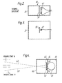
- Figure 1 is a diagrammatic view of a first embodiment of a sorting machine according to the present invention,
- Figures 2 and 3 are respectively a plan view and an elevation of a background unit forming part of the sorting machine of Figure 1,
- Figure 4 illustrates a lighting unit which may be employed in substitution for that illustrated in Figure 1, and
- Figure 5 is a diagrammatic view of a second embodiment of a sorting machine according to the present invention.
- Referring first to Figure 1, a sorting machine according to the present invention comprises a
hopper 10 adapted to containobjects 11 to be sorted. Such objects may, for example, be agricultural products such as peas, beans (e.g. coffee beans), nuts, diced potatoes and rice, or mineral products, such as diamonds and other precious stones and pieces of ore. The term "objects" is used herein in a wide sense so as, for example, to include particulate material.Objects 11 in thehopper 10 may pass to a tray 12 which is, in operation, vibrated by a vibrator 13 so as to cause theobjects 11 to pass, one at a time, to a chute orduct 14 which is disposed at an angle within the range of 100 to 20° (e.g. 150) to the vertical. The chute orduct 14 may be formed of a material having a low coefficient of friction such as anodised aluminium and may be aligned with a chute or duct 15 of similar diameter which is formed of a transparent material such as glass or methyl methacrylate. Alternatively, thesuccessive chutes 14, 15 may be replaced by a single transparent chute, or the chute 15 may be omitted. - The
objects 11, which slide under gravity down thechutes 14, 15 travel sequentially past anupper viewing zone 16 and alower viewing zone 17 so that themoving objects 11 pass to an object separation zone 20 which is disposed beneath theviewing zones lower viewing zones - Lighting of the
upper viewing zone 16 is effected by twolighting units chutes 14, 15 and thus of the moving objects 11. Similarly, lighting of thelower viewing zone 17 is effected by twolighting units chutes 14, 15 and thus on the opposite side of the moving objects 11. Each of the lighting units 21-24 comprise a fluorescent tube or otherlight source 25, anaperture plate 26 having anaperture 27 therein and alens 30. The term "light" is used in this specification in a wide sense to include both visible and non-visible radiation, such as infra-red and ultraviolet radiation. Thelighting units light respective lenses 30 onto an object lla in theupper viewing zone 16. Similarly, thelighting units light respective lenses 30 onto an object llb in thelower viewing zone 17. Thelenses 30 may be constituted by plastics Fresnel lenses. Thebeams beams - The upper and
lower viewing zones lower viewing zones electric detector 37 which views the objects lla, Ilb through a respective lens (or lens tube) 38. The electrical output of eachdetector 37 is amplified in a DC coupledpre-amplifier 39 and passes to aprocessor 40. Theprocessor 40 is programmed so that, under the control of the output from the viewing means 35, 36, it determines whetherobjects 11 which have been viewed by the viewing means 35, 36 are desired or undesired. When anundesired object 11 is detected, e.g. an object which has a discoloured area, theprocessor 40 produces an output signal which is transmitted to effect opening of a valve (not shown) in anair ejector 41, whereby a jet of compressed air is directed onto the undesired object, when the latter reaches the separation zone 20. Thus desired objects pass undeflected to an "accept"container 42 while undesired objects are deflected into a "reject"container 43. - As will be seen from Figure 1, each of the beams 31-34 is out of alignment with any viewing means 35, 36 on either side of the path of the moving objects 11. The angle between each of the beams 31-34 and the optical axis or line of
view optical axis viewing zone light sources 25 which are disposed on opposite sides of the respectiveoptical axis - In the construction described above, which is intended primarily for the sorting of opaque objects such as coffee beans, substantially any light which is reflected by an
object 11 so as to be directed into a viewing means 35, 36 is derived from alight source 25 which is disposed on the same side of the path of the moving objects as the respective viewing means. For example, the "front" of the object lla receives light from thebeams electric detector 37 of the viewing means 35. The disposition of thebeams respective lens 38 onto the respective photo-electric detector 37, whereby the reflected light received by the photo-electric detector is primarily constituted by diffuse reflection from the front of the object lla. Thebeams lighting units beams electric detector 37. Furthermore, thebeams beams light source 25 on one side of the path of theobjects 11 will enter a lens orlens tube 38 on the other side thereof. - The provision of the
apertures 27 andlenses 30 of thelighting units light beams objects 11 passing through the viewing zones. - It will be noted that the beams 31-34 are at "steep" angles so as to effect good top and bottom lighting of the objects being viewed. For example, as previously mentioned, the angle between each of the beams 31-34 and the respective
optical axis - Each of the viewing means 35, 36 views the objects against a
background 46 whose colour or reflectivity is arranged to be as similar as possible to that of the average of the "good" objects. The use of thebackgrounds 46 compensates for variations in the sizes of theobjects 11. As shown in Figures 2 and 3, eachbackground 46 is lit by afilament bulb 47 having abaffle 50 in front of it. Light from the filament bulb is directed onto atranslucent window 51 which is viewed by the respective viewing means 35, 36, thebaffle 50 ensuring that thetranslucent window 51 is diffusely lit. The colour of thetranslucent window 51 is matched to that of the average of the "good" objects. - The brightness of each
background 46 is controlled by theprocessor 40, which adjusts the voltage of the electrical supply to thebackground 46 so that, as described in greater detail in European Patent Specification No. 0 056 513. A2, the brightness of each background is adjusted when necessary by theprocessor 40 so that the background remains appropriate at all times to the objects being viewed. - The lighting of the backgrounds illustrated in Figures 2 and 3 does not produce stray illumination which would be viewed by the viewing means 35, 36 so as to adversely affect the accuracy of the sorting.
- Although one particular method of lighting the background is illustrated in Figures 2 and 3, many other methods are possible which may involve either transmitted or reflected light.
- Although Figure 1 shows one single sorting channel, the sorting machine would in practice have a large number of sorting channels arranged side by side, each channel having its
respective chutes 14, 15, lighting units 21-24, viewing means 35, 36,ejector 41 andbackgrounds 46. However, all the sorting channels would have onecommon processor 40 which, would, inter alia, control theindividual backgrounds 46 so that these would not necessarily all be at the same brightness. Thus such variation in brightness of thebackgrounds 46 may be necessary if thelight sources 25 were constituted by fluorescent tubes extending throughout all the channels, since the light output of such fluorescent tubes is not constant throughout the length of the tubes. - As will be appreciated, in the arrangement described in the previous paragraph, the
objects 11 which move past theviewing zones - By reason of the vertical spacing apart of the
viewing zones processor 40 from the viewing means 35, 36 of each channel will need to be delayed to different extents before being transmitted to therespective ejector 41. However, theprocessor 40 may readily be programmed so that the signal from theupper viewing zone 16 will, after a suitable interval, be combined with that from thelower viewing zone 17 to produce a single accept/reject signal. - As so far described, the sorting machine of Figure 1 is suitable primarily for sorting opaque objects such as coffee beans, in which case the viewing means 35, 36 will merely view light reflected by the opaque objects. In the case of some translucent objects such as rice, however, it may be desirable for the viewing means to view both such reflected light and also light transmitted through the translucent objects. For example, if one is sorting parboiled rice some of whose grains are partially covered by husk,it is difficult to remove the husk-covered grains if use is made only of reflected light since the colour and reflectivity of the husk does not greatly differ from that of the rice itself. However, the husk is opaque so that, if back lighting is employed, light will not be transmitted through the husk and the husk-covered grains can easily be detected and removed.
- In order to be able to effect such back lighting, the construction of Figure 1 described above may be modified so that each of the lighting units 21-24 is modified to produce not only the above-mentioned beams 31-34 but also beams 51-54. Thus each
light source 25 produces a beam 51-54 which is directed to aviewing zone light source 25 of thelighting unit 21 will produce thebeam 31 which is directed to theupper viewing zone 16 and thebeam 51 which is directed to thelower viewing zone 17. The beams 51-54 will illuminate the rear of thetranslucent objects 11 and this illumination will be transmitted through thetranslucent objects 11 so that both this transmitted light and the light which is reflected by the translucent objects will be viewed by the viewing means 35, 36. There may, of course, be some glancing specular reflection produced by the beams 51-54 but, by making the beams 51-54 less powerful than the beams 31-34, it may be arranged that, say, at least 80% of the light which is reflected by an object so as to be directed into a viewing means is derived from a light source disposed on the same side of the said moving objects as the respective viewing means. - Such a modified
lighting unit 55 is shown in Figure 4 and comprises anaperture plate 56 having twoapertures aperture plate 56, i.e. on the side thereof remote from thelight source 25, filters 62, 63 are provided. Filtered beams 64, 65 (corresponding, for example, to thebeams 31, 51) are produced which are substantially focussed by a common Fresnel orother lens 66. By appropriate selection of thefilters beam 65 is less powerful than thebeam 64 so that each viewing means 35, 36 receives a major amount of reflected light which is reflected by an object and is derived from a light source disposed on the same side of the moving objects as the respective viewing means, and a minor amount of transmitted light which is transmitted through the object and is derived from a light source disposed on the opposite side of the moving objects. Thebeam 65 may also be made less powerful than thebeam 64 by appropriate selection of the sizes of theapertures filters - In Figure 5 there is shown a sorting machine which is generally similar to that of Figure 1 and which for this reason will not be described in detail, like reference numerals indicating like parts. In the Figure 5 construction, however, the beams 31-34 from the lighting units 21-24 are directed to the respective viewing zones by way of
mirrors 70, whereby the size of the optical box orsystem 71 may be minimised whilst still providing the best angle of illumination. - Moreover, instead of providing a transparent chute or duct 15, the
objects 11 falling from the lower end of the chute orduct 14 pass through a transparent duct formed by two spaced apart parallel flat sheets orwindows 72, 73 of glass or other transparent material. The optical components may thus be sealed from contamination by the dust entrained with theobjects 11. Thewindows 72, 73 may be easily cleaned. - Parallel glass windows have in the past given rise to the risk that reflection from the surface of the glass may enter the viewing means and so "swamp" the sorting signal and the risk that light scattered from dust on the surface of the glass may affect the sorting signals. However, these problems will not arise in the construction illustrated in Figure 5 since the illumination beams are so positioned that the light reflected from the surface of the glass will not enter the
viewing lenses 38. Similarly, the illumination beams are positioned such that no light falls upon the area of glass which is directly in front of the viewing lens.
Claims (16)
Applications Claiming Priority (2)
| Application Number | Priority Date | Filing Date | Title |
|---|---|---|---|
| GB8317777 | 1983-06-30 | ||
| GB08317777A GB2142426B (en) | 1983-06-30 | 1983-06-30 | Sorting machine and method |
Publications (3)
| Publication Number | Publication Date |
|---|---|
| EP0130715A2 true EP0130715A2 (en) | 1985-01-09 |
| EP0130715A3 EP0130715A3 (en) | 1988-02-03 |
| EP0130715B1 EP0130715B1 (en) | 1989-11-23 |
Family
ID=10545043
Family Applications (1)
| Application Number | Title | Priority Date | Filing Date |
|---|---|---|---|
| EP84303997A Expired EP0130715B1 (en) | 1983-06-30 | 1984-06-13 | Sorting machine |
Country Status (8)
| Country | Link |
|---|---|
| US (1) | US4630736A (en) |
| EP (1) | EP0130715B1 (en) |
| JP (1) | JPS6022977A (en) |
| BR (1) | BR8403268A (en) |
| DE (1) | DE3480530D1 (en) |
| ES (1) | ES8504504A1 (en) |
| GB (1) | GB2142426B (en) |
| IN (1) | IN161155B (en) |
Cited By (12)
| Publication number | Priority date | Publication date | Assignee | Title |
|---|---|---|---|---|
| GB2180062A (en) * | 1985-09-03 | 1987-03-18 | Delta Technology Corp | Sorter for agricultural products |
| EP0238561A1 (en) * | 1985-09-30 | 1987-09-30 | Cra Services | Classifier. |
| WO1993022658A1 (en) * | 1992-04-30 | 1993-11-11 | Simco/Ramic Corporation | Shadowless spherical illumination system for use in an article inspection system |
| DE4340165A1 (en) * | 1993-11-25 | 1995-06-01 | Hergeth Hubert A | Detection and elimination of foreign bodies |
| DE4340173A1 (en) * | 1993-11-25 | 1995-06-01 | Hergeth Hubert A | Detecting and removing alien bodies |
| US5579921A (en) * | 1991-09-30 | 1996-12-03 | Elexso Sortiertechnik Gmbh | Optical sorting system for a color sorting machine and process |
| WO2008020343A2 (en) * | 2006-08-18 | 2008-02-21 | Primus Special Projects (Pty) Ltd | A sorter |
| WO2008134347A2 (en) * | 2007-04-24 | 2008-11-06 | Pioneer Hi-Bred International, Inc. | A method and computer program product for distinguishing and sorting seeds containing a genetic element of interest |
| US8452445B2 (en) | 2007-04-24 | 2013-05-28 | Pioneer Hi-Bred International, Inc. | Method and computer program product for distinguishing and sorting seeds containing a genetic element of interest |
| US8459463B2 (en) | 2007-04-24 | 2013-06-11 | Pioneer Hi-Bred International, Inc. | Method for sorting resistant seed from a mixture with susceptible seed |
| AT15295U1 (en) * | 2015-03-09 | 2017-05-15 | Binder + Co Ag | Sorting out mineral-containing objects or plastic objects |
| EP3681648A4 (en) * | 2017-09-14 | 2021-05-19 | Bomill Ab | Object conveying and/or sorting system |
Families Citing this family (58)
| Publication number | Priority date | Publication date | Assignee | Title |
|---|---|---|---|---|
| US5158181A (en) * | 1985-10-29 | 1992-10-27 | Bailey Roger F | Optical sorter |
| EP0223446B1 (en) * | 1985-10-29 | 1991-03-27 | Roger Frederick Bailey | Optical sorting apparatus |
| US5184732A (en) * | 1985-12-20 | 1993-02-09 | Gersan Establishment | Shape sorting |
| GB8531396D0 (en) * | 1985-12-20 | 1986-02-05 | Gersan Ets | Sorting |
| JPH081368B2 (en) * | 1986-03-25 | 1996-01-10 | 充利 広瀬 | Imaging Method in Shiitake Automatic Sorting System |
| JPH0799326B2 (en) * | 1986-08-30 | 1995-10-25 | 株式会社マキ製作所 | Appearance inspection method and apparatus for spherical articles |
| DE3701335A1 (en) * | 1987-01-19 | 1988-07-28 | Buehler Miag Gmbh | Method and device for optical separation |
| JPS63315179A (en) * | 1987-03-18 | 1988-12-22 | 株式会社 サタケ | Color selector |
| NZ225966A (en) * | 1987-08-28 | 1990-10-26 | Commw Scient Ind Res Org | Colour sorting fibrous material in pneumatic conveyor using light sensor and air jet rejection |
| GB8823570D0 (en) * | 1988-10-07 | 1988-11-16 | Spandrel Etab | Sorting |
| US5056642A (en) * | 1990-09-13 | 1991-10-15 | Unarco Industries, Inc. | Roller track for storage rack, roller conveyor, or similar apparatus |
| US5077477A (en) * | 1990-12-12 | 1991-12-31 | Richard Stroman | Method and apparatus for detecting pits in fruit |
| EP0517950B1 (en) * | 1991-05-21 | 1996-07-10 | Esm International, Inc. | Sorting machine |
| JPH0796253A (en) * | 1993-06-30 | 1995-04-11 | Satake Eng Co Ltd | Bean color classifier |
| US5555984A (en) * | 1993-07-23 | 1996-09-17 | National Recovery Technologies, Inc. | Automated glass and plastic refuse sorter |
| US5339965A (en) * | 1993-08-06 | 1994-08-23 | Allen Fruit Co., Inc. | Granular article sorter having improved fluid nozzle separating system |
| US5954206A (en) * | 1995-07-25 | 1999-09-21 | Oseney Limited | Optical inspection system |
| US6003681A (en) * | 1996-06-03 | 1999-12-21 | Src Vision, Inc. | Off-belt stabilizing system for light-weight articles |
| US6191859B1 (en) | 1996-10-28 | 2001-02-20 | Sortex Limited | Optical systems for use in sorting apparatus |
| US6056127A (en) * | 1996-10-28 | 2000-05-02 | Sortex Limited | Delivery system for sorting apparatus |
| DE19719698A1 (en) * | 1997-05-09 | 1998-11-12 | Wacker Chemie Gmbh | Optoelectronic classifying device |
| JP3654416B2 (en) * | 1998-06-02 | 2005-06-02 | 株式会社サタケ | Granular article level discrimination device |
| JP2000300077A (en) | 1998-09-09 | 2000-10-31 | Satake Eng Co Ltd | Method for determining fertilizing quantity for grain crop, method for estimating quality and yield of grain and apparatus for providing production information on grain |
| US6144004A (en) * | 1998-10-30 | 2000-11-07 | Magnetic Separation Systems, Inc. | Optical glass sorting machine and method |
| KR20000077034A (en) | 1999-04-22 | 2000-12-26 | 사따께 사또루 | Apparatus and method for evaluating quality of granular object |
| ID26384A (en) | 1999-06-17 | 2000-12-21 | Satake Eng Co Ltd | DIAGNOSIS METHOD OF NUTRITIONAL CONDITIONS FROM HARVEST IN FLOOR PLANT |
| ID26882A (en) | 1999-08-10 | 2001-02-15 | Satake Eng Co Ltd | DIAGNOSIS METHOD OF NUTRITION HARVEST RESULT CONDITIONS IN PLANT LADANG |
| US7041926B1 (en) * | 2002-05-22 | 2006-05-09 | Alan Richard Gadberry | Method and system for separating and blending objects |
| MXPA04011737A (en) * | 2002-05-28 | 2005-02-14 | Satake Usa Inc | Illumination source for sorting machine. |
| JP2004012257A (en) * | 2002-06-06 | 2004-01-15 | Yamaha Fine Technologies Co Ltd | Appearance inspection device and appearance inspection method for work |
| US7351929B2 (en) * | 2002-08-12 | 2008-04-01 | Ecullet | Method of and apparatus for high speed, high quality, contaminant removal and color sorting of glass cullet |
| US8436268B1 (en) | 2002-08-12 | 2013-05-07 | Ecullet | Method of and apparatus for type and color sorting of cullet |
| US7355140B1 (en) | 2002-08-12 | 2008-04-08 | Ecullet | Method of and apparatus for multi-stage sorting of glass cullets |
| WO2004045031A2 (en) * | 2002-11-13 | 2004-05-27 | Ackley Machine Corporation | Laser unit, inspection unit, method for inspecting pellet-shaped articles and pharmaceutical article |
| DE102004021689B4 (en) * | 2004-04-30 | 2013-03-21 | Optosort Gmbh | Method and device for sorting refractive particles |
| GB2416533B (en) * | 2004-07-27 | 2008-06-18 | Sortex Ltd | Chutes for sorting and inspection apparatus |
| US7768643B1 (en) * | 2006-03-30 | 2010-08-03 | Key Technology, Inc. | Apparatus and method for classifying and sorting articles |
| US8247724B2 (en) * | 2008-10-20 | 2012-08-21 | Buhler Sortex Ltd. | Chutes for sorting and inspection apparatus |
| US20100230330A1 (en) * | 2009-03-16 | 2010-09-16 | Ecullet | Method of and apparatus for the pre-processing of single stream recyclable material for sorting |
| CN105107758B (en) | 2010-06-01 | 2020-03-03 | 阿克莱机械公司 | Inspection system |
| US8841570B2 (en) * | 2010-10-13 | 2014-09-23 | Paramount Farms International Llc | System and method for aflatoxin detection |
| US8283589B2 (en) * | 2010-12-01 | 2012-10-09 | Key Technology, Inc. | Sorting apparatus |
| CN102553835A (en) * | 2011-01-21 | 2012-07-11 | 安徽捷迅光电技术有限公司 | Light source system for laser color sorting machine |
| GB2492358A (en) | 2011-06-28 | 2013-01-02 | Buhler Sortex Ltd | Optical sorting and inspection apparatus |
| GB2492359A (en) | 2011-06-28 | 2013-01-02 | Buhler Sortex Ltd | Inspection apparatus with alternate side illumination |
| US20130008837A1 (en) * | 2011-07-06 | 2013-01-10 | Key Technology, Inc. | Sorting apparatus |
| DE102011054659A1 (en) * | 2011-10-20 | 2013-04-25 | AeroMegt GmbH | Method and device for measuring aerosols in a large volume flow |
| CN103495566B (en) * | 2013-10-18 | 2015-12-02 | 核工业理化工程研究院华核新技术开发公司 | The online separator of ore of view-based access control model recognition technology |
| UA121201C2 (en) * | 2013-11-01 | 2020-04-27 | Томра Сортінґ Нв | Method and apparatus for detecting matter |
| US9275298B2 (en) | 2014-04-17 | 2016-03-01 | Canon Kabushiki Kaisha | Material classification using specular gloss |
| CN104668204A (en) * | 2014-12-19 | 2015-06-03 | 湖南超牌建材科技有限公司 | Feldspar quarry impurity removal method and device and obtained feldspar quarry |
| FR3048369B1 (en) * | 2016-03-01 | 2018-03-02 | Pellenc Selective Technologies | MACHINE AND METHOD FOR INSPECTING FLOWING OBJECTS |
| DE102016109752A1 (en) * | 2016-05-26 | 2017-11-30 | Sikora Ag | Apparatus and method for inspecting bulk material |
| WO2017212427A1 (en) | 2016-06-07 | 2017-12-14 | Federeación Nacional De Cafeteros De Colombia | Device and method for classifying seeds |
| CN106970056A (en) * | 2017-04-23 | 2017-07-21 | 湖南军芃科技股份有限公司 | A kind of ore machine device for visual identification and its recognition methods based on ultraviolet fluorescent |
| US10293379B2 (en) * | 2017-06-26 | 2019-05-21 | Key Technology, Inc. | Object detection method |
| SG11202000222TA (en) * | 2017-07-10 | 2020-02-27 | Arlanxeo Deutschland Gmbh | Inspection apparatus and method for visual inspecting elastic particles |
| WO2021177173A1 (en) * | 2020-03-05 | 2021-09-10 | 株式会社サタケ | Optical sorting machine |
Citations (5)
| Publication number | Priority date | Publication date | Assignee | Title |
|---|---|---|---|---|
| DE948992C (en) * | 1939-06-22 | 1956-09-13 | Bosch Gmbh Robert | Process for the manufacture of high vacuum pipes |
| GB1516884A (en) * | 1975-04-16 | 1978-07-05 | Xeltron Sa | Optical sorting apparatus |
| US4276983A (en) * | 1978-10-23 | 1981-07-07 | Bickley Manufacturing Company | Sorting apparatus |
| GB2072835A (en) * | 1980-01-21 | 1981-10-07 | Fmc Corp | Apparatus for sorting fruit according to colour |
| EP0065363A1 (en) * | 1981-05-14 | 1982-11-24 | Satake Engineering Co., Ltd. | Photoelectric detection device for color sorting apparatus |
Family Cites Families (8)
| Publication number | Priority date | Publication date | Assignee | Title |
|---|---|---|---|---|
| US2131095A (en) * | 1934-02-15 | 1938-09-27 | Electric Sorting Machine Compa | Means for sorting homogeneous articles |
| US2971646A (en) * | 1959-08-17 | 1961-02-14 | Lilly Co Eli | Article inspection and sorting apparatus |
| GB964432A (en) * | 1961-02-22 | 1964-07-22 | Sciper Sa | Improvements in or relating to machine for sorting articles |
| US3738484A (en) * | 1971-03-15 | 1973-06-12 | Mandrel Industries | Sorting machine |
| US3776381A (en) * | 1972-04-25 | 1973-12-04 | R Wood | Apparatus for sorting products |
| JPS5932729B2 (en) * | 1975-09-16 | 1984-08-10 | 神東エンジニアリング (株) | color sorter |
| US4096949A (en) * | 1976-06-01 | 1978-06-27 | Geosource Inc. | Apparatus for performing a three-way sort |
| JPS5717842A (en) * | 1980-07-07 | 1982-01-29 | Satake Eng Co Ltd | Photoelectric sorting apparatus of color sorter |
-
1983
- 1983-06-30 GB GB08317777A patent/GB2142426B/en not_active Expired
-
1984
- 1984-06-13 EP EP84303997A patent/EP0130715B1/en not_active Expired
- 1984-06-13 DE DE8484303997T patent/DE3480530D1/en not_active Expired
- 1984-06-14 IN IN488/DEL/84A patent/IN161155B/en unknown
- 1984-06-15 US US06/621,253 patent/US4630736A/en not_active Expired - Lifetime
- 1984-06-29 ES ES533862A patent/ES8504504A1/en not_active Expired
- 1984-06-29 JP JP59133464A patent/JPS6022977A/en active Pending
- 1984-07-02 BR BR8403268A patent/BR8403268A/en not_active IP Right Cessation
Patent Citations (5)
| Publication number | Priority date | Publication date | Assignee | Title |
|---|---|---|---|---|
| DE948992C (en) * | 1939-06-22 | 1956-09-13 | Bosch Gmbh Robert | Process for the manufacture of high vacuum pipes |
| GB1516884A (en) * | 1975-04-16 | 1978-07-05 | Xeltron Sa | Optical sorting apparatus |
| US4276983A (en) * | 1978-10-23 | 1981-07-07 | Bickley Manufacturing Company | Sorting apparatus |
| GB2072835A (en) * | 1980-01-21 | 1981-10-07 | Fmc Corp | Apparatus for sorting fruit according to colour |
| EP0065363A1 (en) * | 1981-05-14 | 1982-11-24 | Satake Engineering Co., Ltd. | Photoelectric detection device for color sorting apparatus |
Cited By (22)
| Publication number | Priority date | Publication date | Assignee | Title |
|---|---|---|---|---|
| GB2180062A (en) * | 1985-09-03 | 1987-03-18 | Delta Technology Corp | Sorter for agricultural products |
| GB2180062B (en) * | 1985-09-03 | 1990-05-02 | Delta Technology Corp | Sorter for agricultural products |
| EP0238561A1 (en) * | 1985-09-30 | 1987-09-30 | Cra Services | Classifier. |
| EP0238561A4 (en) * | 1985-09-30 | 1989-03-13 | Cra Services | Classifier. |
| US5579921A (en) * | 1991-09-30 | 1996-12-03 | Elexso Sortiertechnik Gmbh | Optical sorting system for a color sorting machine and process |
| WO1993022658A1 (en) * | 1992-04-30 | 1993-11-11 | Simco/Ramic Corporation | Shadowless spherical illumination system for use in an article inspection system |
| DE4340165A1 (en) * | 1993-11-25 | 1995-06-01 | Hergeth Hubert A | Detection and elimination of foreign bodies |
| DE4340173A1 (en) * | 1993-11-25 | 1995-06-01 | Hergeth Hubert A | Detecting and removing alien bodies |
| WO2008020343A2 (en) * | 2006-08-18 | 2008-02-21 | Primus Special Projects (Pty) Ltd | A sorter |
| WO2008020343A3 (en) * | 2006-08-18 | 2008-04-24 | Primus Special Projects Pty Lt | A sorter |
| WO2008134347A2 (en) * | 2007-04-24 | 2008-11-06 | Pioneer Hi-Bred International, Inc. | A method and computer program product for distinguishing and sorting seeds containing a genetic element of interest |
| WO2008134347A3 (en) * | 2007-04-24 | 2009-02-05 | Pioneer Hi Bred Int | A method and computer program product for distinguishing and sorting seeds containing a genetic element of interest |
| US8452445B2 (en) | 2007-04-24 | 2013-05-28 | Pioneer Hi-Bred International, Inc. | Method and computer program product for distinguishing and sorting seeds containing a genetic element of interest |
| US8459463B2 (en) | 2007-04-24 | 2013-06-11 | Pioneer Hi-Bred International, Inc. | Method for sorting resistant seed from a mixture with susceptible seed |
| US8626337B2 (en) | 2007-04-24 | 2014-01-07 | Pioneer Hi Bred International Inc | Method and computer program product for distinguishing and sorting seeds containing a genetic element of interest |
| US8965564B2 (en) | 2007-04-24 | 2015-02-24 | Pioneer Hi Bred International Inc | Method and computer program product for distinguishing and sorting seeds containing a genetic element of interest |
| US9101964B2 (en) | 2007-04-24 | 2015-08-11 | Pioneer Hi Bred International Inc | Method for sorting resistant seed from a mixture with susceptible seed |
| CN105300935A (en) * | 2007-04-24 | 2016-02-03 | 先锋高级育种国际公司 | A method and computer program product for distinguishing and sorting seeds containing a genetic element of interest |
| AT15295U1 (en) * | 2015-03-09 | 2017-05-15 | Binder + Co Ag | Sorting out mineral-containing objects or plastic objects |
| US10427190B2 (en) | 2015-03-09 | 2019-10-01 | Binder + Co Ag | Sorting out mineral-containing objects or plastic objects |
| EP3681648A4 (en) * | 2017-09-14 | 2021-05-19 | Bomill Ab | Object conveying and/or sorting system |
| US11872596B2 (en) | 2017-09-14 | 2024-01-16 | Bomill Ab | Object conveying and/or sorting system |
Also Published As
| Publication number | Publication date |
|---|---|
| BR8403268A (en) | 1985-06-11 |
| GB2142426A (en) | 1985-01-16 |
| DE3480530D1 (en) | 1989-12-28 |
| IN161155B (en) | 1987-10-10 |
| EP0130715A3 (en) | 1988-02-03 |
| ES533862A0 (en) | 1985-05-01 |
| GB2142426B (en) | 1986-09-17 |
| US4630736A (en) | 1986-12-23 |
| ES8504504A1 (en) | 1985-05-01 |
| EP0130715B1 (en) | 1989-11-23 |
| GB8317777D0 (en) | 1983-08-03 |
| JPS6022977A (en) | 1985-02-05 |
Similar Documents
| Publication | Publication Date | Title |
|---|---|---|
| EP0130715B1 (en) | Sorting machine | |
| EP0719598B1 (en) | Color sorting apparatus for grains | |
| EP0146299B1 (en) | Sorting machine | |
| CA2268109C (en) | High throughput sorting system | |
| EP0238561B1 (en) | Classifier | |
| EP0727260B1 (en) | Cereal grain color sorting apparatus | |
| US5692621A (en) | Sorting apparatus | |
| CA1243752A (en) | Method and apparatus for detecting and removing foreign material from a stream of particulate matter | |
| EP0060493B1 (en) | Apparatus for detecting cracked rice grain | |
| EP0227404B1 (en) | Sorting | |
| US3939983A (en) | Apparatus for sorting tobacco leaves | |
| NL8620285A (en) | ||
| EP0517950B1 (en) | Sorting machine | |
| US3914601A (en) | Compact viewing assembly for light sensitive sorting machine | |
| US5508512A (en) | Sorting machine using dual frequency optical detectors | |
| US5631460A (en) | Sorting machine using dual frequency optical detectors | |
| US5579921A (en) | Optical sorting system for a color sorting machine and process | |
| US5010247A (en) | Method of classifying objects according to shape | |
| EP0968772A2 (en) | A sorting machine | |
| JPS58159882A (en) | Selector for granular material | |
| JPH09304182A (en) | Grain color selector | |
| RU1771826C (en) | Device for member sorter | |
| EP0865833A2 (en) | A reflective background for a sorting machine |
Legal Events
| Date | Code | Title | Description |
|---|---|---|---|
| PUAI | Public reference made under article 153(3) epc to a published international application that has entered the european phase |
Free format text: ORIGINAL CODE: 0009012 |
|
| AK | Designated contracting states |
Designated state(s): BE CH DE FR GB IT LI NL |
|
| RAP1 | Party data changed (applicant data changed or rights of an application transferred) |
Owner name: SORTEX LIMITED |
|
| PUAL | Search report despatched |
Free format text: ORIGINAL CODE: 0009013 |
|
| AK | Designated contracting states |
Kind code of ref document: A3 Designated state(s): BE CH DE FR GB IT LI NL |
|
| 17P | Request for examination filed |
Effective date: 19880505 |
|
| 17Q | First examination report despatched |
Effective date: 19880712 |
|
| ITF | It: translation for a ep patent filed |
Owner name: ING. PIOVESANA PAOLO |
|
| GRAA | (expected) grant |
Free format text: ORIGINAL CODE: 0009210 |
|
| AK | Designated contracting states |
Kind code of ref document: B1 Designated state(s): BE CH DE FR GB IT LI NL |
|
| PG25 | Lapsed in a contracting state [announced via postgrant information from national office to epo] |
Ref country code: NL Effective date: 19891123 Ref country code: LI Effective date: 19891123 Ref country code: CH Effective date: 19891123 Ref country code: BE Effective date: 19891123 |
|
| ET | Fr: translation filed | ||
| REF | Corresponds to: |
Ref document number: 3480530 Country of ref document: DE Date of ref document: 19891228 |
|
| REG | Reference to a national code |
Ref country code: CH Ref legal event code: PL |
|
| NLV1 | Nl: lapsed or annulled due to failure to fulfill the requirements of art. 29p and 29m of the patents act | ||
| PLBE | No opposition filed within time limit |
Free format text: ORIGINAL CODE: 0009261 |
|
| STAA | Information on the status of an ep patent application or granted ep patent |
Free format text: STATUS: NO OPPOSITION FILED WITHIN TIME LIMIT |
|
| 26N | No opposition filed | ||
| ITTA | It: last paid annual fee | ||
| REG | Reference to a national code |
Ref country code: GB Ref legal event code: IF02 |
|
| PGFP | Annual fee paid to national office [announced via postgrant information from national office to epo] |
Ref country code: FR Payment date: 20020423 Year of fee payment: 19 |
|
| PGFP | Annual fee paid to national office [announced via postgrant information from national office to epo] |
Ref country code: GB Payment date: 20020605 Year of fee payment: 19 |
|
| PGFP | Annual fee paid to national office [announced via postgrant information from national office to epo] |
Ref country code: DE Payment date: 20020902 Year of fee payment: 19 |
|
| PG25 | Lapsed in a contracting state [announced via postgrant information from national office to epo] |
Ref country code: GB Free format text: LAPSE BECAUSE OF NON-PAYMENT OF DUE FEES Effective date: 20030613 |
|
| PG25 | Lapsed in a contracting state [announced via postgrant information from national office to epo] |
Ref country code: DE Free format text: LAPSE BECAUSE OF NON-PAYMENT OF DUE FEES Effective date: 20040101 |
|
| GBPC | Gb: european patent ceased through non-payment of renewal fee |
Effective date: 20030613 |
|
| PG25 | Lapsed in a contracting state [announced via postgrant information from national office to epo] |
Ref country code: FR Free format text: LAPSE BECAUSE OF NON-PAYMENT OF DUE FEES Effective date: 20040227 |
|
| REG | Reference to a national code |
Ref country code: FR Ref legal event code: ST |