EP0130542A1 - Grinding wheel and manufacturing method thereof - Google Patents
Grinding wheel and manufacturing method thereof Download PDFInfo
- Publication number
- EP0130542A1 EP0130542A1 EP84107355A EP84107355A EP0130542A1 EP 0130542 A1 EP0130542 A1 EP 0130542A1 EP 84107355 A EP84107355 A EP 84107355A EP 84107355 A EP84107355 A EP 84107355A EP 0130542 A1 EP0130542 A1 EP 0130542A1
- Authority
- EP
- European Patent Office
- Prior art keywords
- grinding wheel
- abrasive grains
- wheel according
- bond
- grinding
- Prior art date
- Legal status (The legal status is an assumption and is not a legal conclusion. Google has not performed a legal analysis and makes no representation as to the accuracy of the status listed.)
- Granted
Links
Images


Classifications
-
- B—PERFORMING OPERATIONS; TRANSPORTING
- B24—GRINDING; POLISHING
- B24D—TOOLS FOR GRINDING, BUFFING OR SHARPENING
- B24D3/00—Physical features of abrasive bodies, or sheets, e.g. abrasive surfaces of special nature; Abrasive bodies or sheets characterised by their constituents
- B24D3/34—Physical features of abrasive bodies, or sheets, e.g. abrasive surfaces of special nature; Abrasive bodies or sheets characterised by their constituents characterised by additives enhancing special physical properties, e.g. wear resistance, electric conductivity, self-cleaning properties
- B24D3/342—Physical features of abrasive bodies, or sheets, e.g. abrasive surfaces of special nature; Abrasive bodies or sheets characterised by their constituents characterised by additives enhancing special physical properties, e.g. wear resistance, electric conductivity, self-cleaning properties incorporated in the bonding agent
-
- B—PERFORMING OPERATIONS; TRANSPORTING
- B24—GRINDING; POLISHING
- B24D—TOOLS FOR GRINDING, BUFFING OR SHARPENING
- B24D3/00—Physical features of abrasive bodies, or sheets, e.g. abrasive surfaces of special nature; Abrasive bodies or sheets characterised by their constituents
-
- B—PERFORMING OPERATIONS; TRANSPORTING
- B24—GRINDING; POLISHING
- B24D—TOOLS FOR GRINDING, BUFFING OR SHARPENING
- B24D3/00—Physical features of abrasive bodies, or sheets, e.g. abrasive surfaces of special nature; Abrasive bodies or sheets characterised by their constituents
- B24D3/34—Physical features of abrasive bodies, or sheets, e.g. abrasive surfaces of special nature; Abrasive bodies or sheets characterised by their constituents characterised by additives enhancing special physical properties, e.g. wear resistance, electric conductivity, self-cleaning properties
-
- C—CHEMISTRY; METALLURGY
- C09—DYES; PAINTS; POLISHES; NATURAL RESINS; ADHESIVES; COMPOSITIONS NOT OTHERWISE PROVIDED FOR; APPLICATIONS OF MATERIALS NOT OTHERWISE PROVIDED FOR
- C09K—MATERIALS FOR MISCELLANEOUS APPLICATIONS, NOT PROVIDED FOR ELSEWHERE
- C09K3/00—Materials not provided for elsewhere
- C09K3/14—Anti-slip materials; Abrasives
- C09K3/1436—Composite particles, e.g. coated particles
- C09K3/1445—Composite particles, e.g. coated particles the coating consisting exclusively of metals
Abstract
Description
- The present invention relates to an improvement in a grinding wheel and, more particularly, to a grinding wheel suitable for heavy or hard grinding and a manufacturing method thereof.
- A grinding wheel using so-called super hard abrasive grains such as diamond, silicon nitride or boron nitride is superior in hardness, durability and wear resistance. Such a grinding wheel is used for various types of workpieces including hard grinding workpieces such as super hard alloys, stone, concrete, glass or ceramics. This type of grinding wheel includes a metal bond grinding wheel, a resinoid bond grinding wheel, or a vitrified bond grinding wheel. This classification is based on the type of bond used for bonding abrasive grains since the performance of the resultant grinding wheel is known to vary significantly in accordance with the type and structure of bond used.
- A metal bond grinding wheel is shown in Fig. 1 wherein
abrasive grains 1 are held using a metal such as Ni as a bond. This grinding wheel has a strong abrasive grain retaining force, and excellent durability and wear resistance. However, this grinding wheel also has poor penetrative ability and cutting properties, and forms only a small number of chip pockets which are easily loaded. In view of this problem, a grinding wheel having a relatively low abrasive grain density of about 75 is generally used. However, this grinding wheel has a low grinding efficiency and cannot provide a satisfactory performance for heavy and hard grinding. - In contrast to this, a resinoid bond grinding wheel using an organic polymeric substance as a bond is superior in the penetrative ability and cutting properties than the metal bond grinding wheel. However, the-resinoid bond grinding wheel has a poor abrasive grain retaining force and is not therefore suitable for . heavy and hard grinding. The same applies to a vitrified bond grinding wheel.
- In view of these problems, a grinding wheel (Fig. 2) has been previously proposed by the present applicant as U.S.P. S.N. 492,826 (filed on May 9, 1983). Referring to Fig. 2, this grinding wheel has a structure wherein
abrasive grains 1 are coated with electricallyconductive coating films 3, and theabrasive grains 1 thus coated with theconductive films 3 are bonded with abond 2 comprising an organic polymeric substance. Due to strong bonding strength between thefilms 3 and thebond 2, the retaining force of theabrasive grains 1 is improved and the abrasive grain density and grinding performance are improved over a conventional resinoid bond grinding wheel or the like. However, this grinding wheel still has a problem of wear of thebond 2, leaving room for further improvements in grinding efficiency, ground surface state and the like. - It is an object of the present invention to provide a grinding wheel having a high abrasive grain density and a manufacturing method thereof, wherein when the grinding wheel is used for high-efficiency grinding or heavy or hard grinding, the grinding ratio is high, wear of the grinding wheel is small, and the grinding efficiency and the surface state (Roughness) after grinding are both improved.
- In order to achieve this object of the present invention, there is provided a grinding wheel, comprising a number of abrasive grains coated with an electrically conductive substance, a nonconductive bond for bonding the super hard abrasive grains, and a diamond filler dispersed in the bond.
- There is also provided according to the present invention a method of manufacturing a grinding wheel, comprising the steps of: coating abrasive grains with conductive films in an amount of 30 to 80 wt% based on a content of the abrasive grains; homogeneously mixing the coated abrasive grains, a nonconductive bond, and a diamond filler; injecting a resultant mixture into a mold; and molding under pressure the injected mixture at a predetermined temperature.
- In a grinding wheel of the present invention, a number of abrasive grains are coated with conductive films and are bonded thereby. The abrasive grains are bonded with a bond through the conductive films. A filler comprising diamond particles is dispersed in the bond so as to reinforce the retaining force of the abrasive grains. Chip pockets can be easily formed by removal of the filler during grinding. Therefore, the grinding wheel of the present invention has an improved grinding efficiency, allows the use of the filler as a cutting edge, and improves the state of the ground surface. The grinding wheel of the present invention can be conveniently used for high-efficiency grinding and heavy or hard grinding.
- This invention can be more fully understood from the following detailed description when taken in conjunction with the accompanying drawings, in which:
- Fig. 1 is an enlarged representation showing the internal structure of a conventional metal bond grinding wheel;
- Fig. 2 is an enlarged representation showing the internal structure of a grinding wheel previously proposed by the present inventors;
- Fig. 3A is a partially cutaway plan view showing an example of a grinding wheel according to the present invention;
- Fig. 3B is a sectional view of the grinding wheel shown in Fig. 3A taken along the line III - III therein;
- Fig. 4 is an enlarged representation showing the internal structure of a grinding wheel according to the present invention;
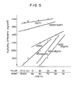
- Fig. 5 is a graph showing the flexural strength as a function of the volume content ratio of filler to bond, using filler of various grain sizes;
- Fig. 6 is a graph showing the flexural strength as a function of the volume mixing ratio of filler, diamond grain and bond, using filler of various grain sizes;
- Fig. 7 is a graph showing the grinding ratio as a function of grinding distance of various grinding wheels;
- Fig. 8 is a graph showing a residual thickness left uncut as a function of grinding distance of various grinding wheels; and
- Fig. 9 is a graph showing depth of wear of the grinding wheel as a function of grinding distance.
- The preferred embodiment of the present invention will now be described with reference to the accompanying drawings.
- Figs. 3A and 3B show an example of a grinding wheel wherein an
abrasive grain portion 11 is formed around the outer periphery of adisc 10. Thedisc 10 consists of a metal such as At and has a through hole 10a for allowing thedisc 10 to be mounted on a rotating shaft of a grinder. Theabrasive grain portion 11 is formed around thedisc 10 through aring 12 of an organic polymeric substance such as a phenolic resin. If theabrasive grain portion 11 is conductive and required to be electrically connected to thedisc 10, a conductive paint is applied across thering 12 to formconductive layers 13, as indicated by broken lines in Fig. 3B. - Fig. 4 is an enlarged representation of the
abrasive grain portion 11. Theabrasive grain portion 11 consists of a number ofabrasive grains 15,conductive coating films 14 covering each of theabrasive grains 15 and being contacted each other, abond 16 filled between theabrasive grains 15 coated with thefilms 14 so as to bond them, and adiamond filler 17 dispersed in thebond 16. Theabrasive grains 15 may be synthetic or natural diamond grains, cubic silicon nitride grains or cubic boron nitride grains having a grain distribution falling within 40 to 1,000 U.S. mesh. The example shown in the drawings uses diamond abrasive grains. The material for forming thecoating films 14 covering theabrasive grains 15 must be one which has good adhesion with theabrasive grains 15, and a satisfactory strength to prevent undesirable removal of theabrasive grains 15 during grinding, and one which can easily deform for attaining good bonding during a hot-pressing step for manufacturing a grinding wheel, to be described later. Examples of such a material include Cu, Ag, Au, Sn, Zn, AQ, Ni and Cr, or alloys thereof. Thecoating film 14 is formed on theabrasive grains 15 as a single layer film of a single metal or metal alloy selected from those enumerated above by a known method such as plating or vacuum deposition. However, in order to reinforce the function of thecoating film 14, thefilm 14 can comprise a two- or multi-layer structure of the same or different metals. - The two-layer structure preferably comprises a first layer which is directly in contact with the
abrasive grains 15 and which consists of a relatively soft metal with good adhesion with the grains, and a second layer which covers the first layer and which consists of a relatively hard metal. When the two-layer structure is to comprise a single material, the first layer can, for example, be formed by electroless nickel plating and the second layer can be formed thereover by electrolytic nickel plating. When the two-layer structure is to comprise different metals, the first layer can, for example, be formed by copper plating and the second layer can be formed by nickel plating. - The
bond 16 must have good adhesion with thecoating films 14. Examples of such a bond include various synthetic polymeric substances such as a phenolic resin, epoxy resin, polyamide, unsaturated polyester, polyimide, polyacetal, or polyacryl; and natural organic polymeric substances such as shellac. Thediamond filler 17 to be dispersed in thebond 16 must have a grain size smaller than that of theabrasive grains 15 and has a mesh size of preferably about 1/2 to 1/20 and more preferably 1/5 to 1/10 of the abrasive grain. In this case, the thickness of thefiller 17 is preferably smaller than that of thecoating films 14 formed on theabrasive grains 15. - In order to provide a satisfactory
abrasive grain portion 11, the amount of thecoating films 14 must be 30 to 80 wt% based on the content of theabrasive grains 15, and theportion 11 must contain the.abrasive grains 15 coated with thefilms 14 in the amount of 33 to 64 vol%. Especially when theabrasive grain portion 11 must have electrical conductivity, the amount of the abrasive grains coated with thefilms 14 must fall within the range of 40 to 64 vol%. The amount of thefiller 17 in thebond 16 preferably falls within the range of 3 to 30 vol%. When the amount of thefiller 17 dispersed in thebond 16 falls within this range, the flexural strength is improved significantly, as will be demonstrated by the results obtained from experiments conducted by the present inventors. Thefiller 17 is mostly dispersed and fixed in thebond 16 during the manufacture of the grinding wheel. However, a portion of thefiller 17 is inserted between the coatingfilms 14 after bonding with the adjacentabrasive grains 15 and is fixed there. - The method of.manufacturing the grinding wheel as described above will now be described. The
disc 10 of a predetermined shape is formed by grinding or the like. Thering 12 of an organic polymeric substance is formed on the outer periphery of thedisk 10. Thedisc 10 with thering 12 mounted thereon is placed in a hot-pressing mold defining an annular groove of a predetermined size between itself and the outer periphery of thering 12. - The
abrasive grain portion 11 is formed in the following procedures.Abrasive grains 15 having a desired grain size distribution are selected. A metal selected from those enumerated hereinabove is coated on the surfaces of theabrasive grains 15 by plating or vacuum deposition so as to form coatingfilms 14 thereon. Abond 16, such as a phenolic resin, and thediamond filler 17 are added in prescribed amounts to theabrasive grains 15 coated with thefilms 14 and the mixture is homogeneously mixed. This mixture is injected into the annular groove formed between thering 12 and the hot-pressing mold. The mixture is hot-pressed while the mixture, the disc .10 and the mold are kept at a predetermined temperature. The heating/pressure conditions for this hot-pressing differ in accordance with the type of a metal used for coating the abrasive grains, the type of bond, the amount of the metal coating on the abrasive grains, and the mixing ratio of theabrasive grains 15 coated with the metal, thebond 16 and thefiller 17. Especially, the temperature for pressing must fall within a range such that thebond 16 is softened or is decreased in viscosity so as to emit gases contained therein. Pressing prevents the expansion of the bond due to gases contained therein and allows plastic deformation of the metal covering theabrasive grains 15, thereby facilitating adhesion between the coating films and the abrasive grains. Pressing at the predetermined temperature can be performed intermittently a plurality of times. This intermittent pressing further facilitates emission of the gases and plastic deformation of the coating metal. In other words, heating and pressing conditions in this hot-pressing process are important factors in improving the abrasive grain density. This hot-pressing substantially eliminates pores in the bond and allows formation of theabrasive grain portion 11 of a dense structure wherein the metal films covering theabrasive grains 15 are securely bonded with each other and theabrasive grains 15 are fixed at a high density. . Upon the plastic deformation of thecoating metal 14, thefiller 17 in thebond 16 is mostly expelled from the bonding portion between thefilms 14 of adjacentabrasive grains 15. However, thefiller 17 is partially left at such bonding portions and is fixed therein. In order to obtain firm adhesion between theabrasive grain portion 11 and thering 12, an adhesive may be applied on the outer periphery of thering 12. - The
abrasive grain portion 11 formed by hot-pressing is forcibly or naturally cooled while still under pressure. Theportion 11 together with thedisc 10 are released from the hot-pressing mold. The grinding wheel is completed after finishing processes of thedisc 10 and thering 12, size correction of theportion 11, and dressing. - Alternatively, an annular
abrasive grain portion 11 is molded with a pair of hot-pressing molds. Theportion 11 is fitted around adisc 10 with aring 12 and is adhered with an adhesive. - A section of the
portion 11 can be observed under a microscope so as to determine if theportion 11 has a satisfactory structure as shown in Fig. 4. However, if thecoating films 14 covering theabrasive grains 15 are bonded to each other, the structure of theportion 11 can be nondestructively tested by conductivity measurement. The conductivity of theportion 11 can be measured in the following manner. A low voltage of about 10 V is applied to ends of a diametrical line of theportion 11, ends of two diametrical lines which are spaced apart by 90°, or any two points on theportion 11 which are spaced apart from each other by a predetermined distance. Application of such a voltage is repeated a plurality of times for different diametrical directions or for different pairs of points. - The performance of the grinding wheel manufactured in this manner will now be described. Fig. 5 shows the flexural strength of members (without abrasive grains '15) which were manufactured by variously changing the mixing ratio of fillers (diamond particles) (f) 17 of various grain size and bond (phenolic resin) (b) 16. The flexural strength of the grinding wheel is associated with the strength of the grinding wheel and with the abrasive grain retaining force thereof. Referring to the graph shown in Fig. 5, a maximum flexural strength is obtained when the abrasive grain of the
filler 17 is minimum (2 pm). The flexural strength is seen to decrease with an increase in the grain size of thefiller 17. For afiller 17 of the same grain size, the flexural strength is increased with an increase in the content of thefiller 17. - Fig. 6 shows the flexural strength of grinding wheels as a function of the contents of a filler and a bond using the grain size of the filler as a parameter. These grinding wheels contained a predetermined amount (47 vol%) of diamond abrasive grains (g) 15 having a grain size distribution of #100/120 (120 µm to 150 µm) and covered with
Ni coating films 14 in the amount of 56 wt%. The contents of the filler comprising diamond particles and the bond comprising a phenolic resin to be mixed with the abrasive grains were varied. The results shown in Fig. 6 reveal the following facts. A grinding wheel which does not contain the filler 17 (other conditions are the same) has a flexural strength of 660 kg/cm2. However, when thefiller 17 is dispersed in thebond 16 of such a grinding wheel, the flexural strength of the resultant grinding wheel changes in accordance with the content of thefiller 17. When the content of thefiller 17 falls within a range between 3 and 30 vol%, the grinding wheel has a higher flexural strength than that of the grinding wheel which does not contain thefiller 17 at all. This fact indicates that the strength and abrasive grain retaining force of the grinding wheel change in accordance with the content of thefiller 17. When the diamond abrasive grains having 'a grain size distribution of #100/120 are used and the grain size of thefiller 17 is #800, a maximum flexural strength is obtained when thefiller 17 is added in the amount of 11 vol%. In this manner, an optimum mixing ratio of thefiller 17 with respect to theabrasive grains 15 is present in accordance with the grain size of thefiller 17. - The grinding performance of the grinding wheel of the present invention will be illustrated below together with the same of other grinding wheels. Table 1 below shows the materials and their amounts for three types of grinding wheels tested. Grinding wheel A is a grinding wheel of the present invention (
abrasive grains 15 have a grain size distribution of #100/120, and afiller 17 has a grain size of 20 um). Grinding wheel B is a grinding wheel according to U.S.P. S.N. 492,826 whereinabrasive grains 15 are covered withcoating films 14 and bonded with a bond 16 (afiller 17 is not dispersed in the bond 16). Grinding wheel C is a commercially available hard grinding wheel. The grinding test was performed with known inorganic hard grinding materials as heat- and wear-resistant materials.
- The grinding ratio G in Fig. 7 represents the relationship between the grinding ratio and the grinding distance. As shown in Fig. 7, the grinding wheel B (previously proposed by the same applicant which has
abrasive grains 15 covered with thecoating films 14 and bonded with the bond 16) has a significantly higher grinding ratio G than the grinding wheel C. However, the grinding wheel A of the present invention has a still higher grinding ratio G than the grinding wheel B not to mention the grinding wheel C. The uncut distance represents the difference between the preset grinding amount and the actual grinding amount. As can be seen from Fig. 8, the grinding wheel B has a smaller uncut distance than that of the grinding wheel C. However, the grinding wheel A of the present invention has a still smaller uncut distance and therefore is capable of high-precision grinding. Fig. 9 shows the depth of wear of the grinding wheel as a function of total grinding distance. It is seen from Fig. 9 that the grinding wheel B has a smaller wear than the grinding wheel C but the grinding wheel A has a still smaller and stabler wear than the grinding wheel B. - In order to clearly demonstrate the good grinding performance of the grinding wheel A of the present invention, Table 2 below shows various properties of the grinding wheels A, B and C for the same grinding distance.

- Table 2 shows as evaluation items the grindability as the ratio of the actual grinding amount to the preset grinding amount in place of the uncut thickness, the grinding efficiency Z', and the roughness of the ground surface in addition to the grinding ratio and the wear depth. The grinding efficiency Z' was tested by wet grinding using a surface grinding machine. The grinding amount was preset to be 60 pm/pass, the grinding wheel velocity was set to be 1800 m/min, and the table moving velocity (workpiece moving velocity) was set to be 20.6 m/min (15 m/min for the grinding wheel C).
- It is seen from Table 2 that the grinding wheel A of the present invention has an excellent grinding ratio, and grindability and wear properties as well as excellent grinding efficiency and smoothness of the ground surface as compared to the grinding wheels B and C. The results shown also indicate that with a
filler 17 having a smaller grain size the ground surface will be smoother. - Such excellent properties of the grinding wheel of the-present invention are attributed to the following reasons. The first reason is a good abrasive grain retaining force. This good abrasive grain retaining force is obtained since the
abrasive grains 15 serving as a cutting edge are completely covered with and securely held by the coatingfilms 14 which are bonded to each other, and theabrasive grains 15 are furthermore held through thecoating films 14 by thebond 16 in which adiamond filler 17 is dispersed. Thediamond filler 17 partially extends into thecoating films 14 covering theabrasive grains 15 to provide a dispersion strengthening phenomenon notably higher than other hard materials. Secondly, the grinding wheel of the present invention containing a diamond filler has a greater number of abrasive grains, that is, a higher abrasive grain density (130 or more) than the conventional grinding wheel. Thirdly, thefiller 17 comprising diamond particles dispersed in thebond 16 allows easy chip pockets to be formed upon removal during grinding so as to prevent frequent loading. Fourthly, thefiller 17 also serves as a secondary cutting edge to allow fine grinding. When the grain size of thefiller 17 is rendered small as compared to theabrasive grains 15, the resultant grinding wheel has an improved strength, a longer life and produces a smoother ground surface in addition to the advantages as described above. - According to the present invention, an indefinite number of abrasive grains coated with conductive films are bonded to each other through a bond, and a hard filler is dispersed in the bond. Thus, the abrasive grain retaining force can be reinforced by the bonding force between the coating films. Removal of the filler during grinding allows easy formation of chip pockets to improve the grinding efficiency. The filler also serves as a cutting edge to improve the smoothness of the ground surface. A highly efficient grinding wheel suitable for heavy or hard grinding is therefore provided.
Claims (22)
Applications Claiming Priority (2)
| Application Number | Priority Date | Filing Date | Title |
|---|---|---|---|
| JP115445/83 | 1983-06-27 | ||
| JP58115445A JPS609660A (en) | 1983-06-27 | 1983-06-27 | Grinding wheel |
Publications (2)
| Publication Number | Publication Date |
|---|---|
| EP0130542A1 true EP0130542A1 (en) | 1985-01-09 |
| EP0130542B1 EP0130542B1 (en) | 1987-01-14 |
Family
ID=14662723
Family Applications (1)
| Application Number | Title | Priority Date | Filing Date |
|---|---|---|---|
| EP84107355A Expired EP0130542B1 (en) | 1983-06-27 | 1984-06-26 | Grinding wheel and manufacturing method thereof |
Country Status (4)
| Country | Link |
|---|---|
| US (1) | US4561863A (en) |
| EP (1) | EP0130542B1 (en) |
| JP (1) | JPS609660A (en) |
| DE (1) | DE3461996D1 (en) |
Cited By (5)
| Publication number | Priority date | Publication date | Assignee | Title |
|---|---|---|---|---|
| EP0179404A2 (en) * | 1984-10-22 | 1986-04-30 | Toyoda Van Moppes Kabushiki Kaisha | Grinding tool |
| EP0482412A2 (en) * | 1990-10-22 | 1992-04-29 | Norton Company | Abrasive product and method of its use |
| EP0520776A2 (en) * | 1991-06-27 | 1992-12-30 | General Electric Company | Method of applying metal coatings on diamond |
| WO1997037815A1 (en) * | 1996-04-10 | 1997-10-16 | Norton Company | Vitreous grinding tool containing metal coated abrasive |
| CN109159035A (en) * | 2018-09-05 | 2019-01-08 | 扬中市飞宇磨具有限公司 | A kind of high-precision auto parts and components processing grinding abrasive disk and its production technology |
Families Citing this family (20)
| Publication number | Priority date | Publication date | Assignee | Title |
|---|---|---|---|---|
| US4681600A (en) * | 1984-09-05 | 1987-07-21 | Extrude Hone Corporation | Cutting tool fabrication process |
| JPS61192480A (en) * | 1985-02-22 | 1986-08-27 | Kanebo Ltd | Synthetic grinding stone for soft metal |
| EP0272531B1 (en) * | 1986-12-08 | 1991-07-31 | Sumitomo Electric Industries Limited | Surface grinding machine |
| US5022895A (en) * | 1988-02-14 | 1991-06-11 | Wiand Ronald C | Multilayer abrading tool and process |
| US4913708A (en) * | 1988-11-18 | 1990-04-03 | Norton Company | Grinding wheel |
| JPH0722895B2 (en) * | 1988-12-29 | 1995-03-15 | ノリタケダイヤ株式会社 | High thermal conductivity grinding wheel |
| JPH02284872A (en) * | 1989-04-24 | 1990-11-22 | Fsk Corp | Superabrasive grain grindstone and grinding paste |
| US5095052A (en) * | 1990-06-28 | 1992-03-10 | The United States Of America As Represented By The Secretary Of The Air Force | Low impulse coatings |
| US5089032A (en) * | 1990-07-05 | 1992-02-18 | Moran Joseph F | Grinding wheel |
| US5052153A (en) * | 1990-09-06 | 1991-10-01 | Wiand Ronald C | Cutting tool with polycrystalline diamond segment and abrasive grit |
| JP4898016B2 (en) * | 2001-04-27 | 2012-03-14 | 株式会社ノリタケカンパニーリミテド | Honing wheel for gears |
| JP4737492B2 (en) * | 2001-09-04 | 2011-08-03 | 独立行政法人理化学研究所 | Metalless bond grindstone and electrolytic dressing grinding method and apparatus using the same |
| JP4721264B2 (en) * | 2005-04-21 | 2011-07-13 | 株式会社吉野工業所 | Combination container |
| EP2177318B1 (en) * | 2009-04-30 | 2014-03-26 | Saint-Gobain Abrasives, Inc. | Abrasive article with improved grain retention and performance |
| US8821606B2 (en) * | 2009-07-21 | 2014-09-02 | Honda Motor Co., Ltd. | Metal bonded grinding stone, and method of manufacturing the same |
| US20130291445A1 (en) * | 2012-05-01 | 2013-11-07 | Sigma Innovation Technology Inc. | Diamond abrasive grain and electroplated tool having the same |
| US9937604B2 (en) * | 2013-06-26 | 2018-04-10 | Saint-Gobain Abrasives, Inc. | Abrasive article and method of making same |
| JP5721877B2 (en) * | 2014-03-04 | 2015-05-20 | 株式会社東京精密 | Thin blade |
| CN109096990A (en) * | 2017-06-21 | 2018-12-28 | 圣戈本陶瓷及塑料股份有限公司 | The modified abrasive grains in surface, abrasive article with and forming method thereof |
| US20230001543A1 (en) * | 2019-12-16 | 2023-01-05 | 3M Innovative Properties Company | Bonded abrasive article and method of making the same |
Citations (3)
| Publication number | Priority date | Publication date | Assignee | Title |
|---|---|---|---|---|
| US3904391A (en) * | 1965-09-22 | 1975-09-09 | Asea Ab | Metal-coated diamonds in synthetic resin bonded grinding wheels |
| GB1428937A (en) * | 1973-07-27 | 1976-03-24 | De Beers Ind Diamond | Metal coated abrasive particles |
| GB1437471A (en) * | 1972-06-30 | 1976-05-26 | Gen Electric | Abrasive composition and grinding wheel |
Family Cites Families (11)
| Publication number | Priority date | Publication date | Assignee | Title |
|---|---|---|---|---|
| US3062633A (en) * | 1958-12-30 | 1962-11-06 | Norton Co | Electrically conductive organic bonded grinding wheel |
| US4021208A (en) * | 1972-08-07 | 1977-05-03 | Tyrolit-Schleifmittelwerk Swarovski K.G. | Abrasive article |
| ZA741474B (en) * | 1974-03-07 | 1975-10-29 | Edenvale Eng Works | Abrasive tools |
| GB1489665A (en) * | 1974-09-04 | 1977-10-26 | Inoue Japax Res | Electrochemical abrasive machining |
| JPS5244478A (en) * | 1975-10-04 | 1977-04-07 | Tsuyoshi Kato | Adjustment device for multi-purpose deformed forming |
| JPS5244673A (en) * | 1975-10-04 | 1977-04-07 | Koji Noma | Loss angle measuring instrument |
| US4099934A (en) * | 1976-07-29 | 1978-07-11 | Toyoda Koki Kabushiki Kaisha | Method for manufacturing resinoid-bonded grinding tools |
| ZA781390B (en) * | 1978-03-09 | 1979-04-25 | De Beers Ind Diamond | The metal coating of abrasive particles |
| JPS5649708A (en) * | 1979-09-29 | 1981-05-06 | Asahi Chem Ind Co Ltd | Catalyst for alpha-olefin polymerization |
| CA1194318A (en) * | 1981-05-18 | 1985-10-01 | Edwin A. Pascoe | Dry grinding cemented carbide workpieces with silver- coated diamond grit |
| US4435189A (en) * | 1982-01-15 | 1984-03-06 | General Electric Company | Method of preparing rough textured metal coated abrasives and product resulting therefrom |
-
1983
- 1983-06-27 JP JP58115445A patent/JPS609660A/en active Granted
-
1984
- 1984-06-26 US US06/624,771 patent/US4561863A/en not_active Expired - Lifetime
- 1984-06-26 DE DE8484107355T patent/DE3461996D1/en not_active Expired
- 1984-06-26 EP EP84107355A patent/EP0130542B1/en not_active Expired
Patent Citations (3)
| Publication number | Priority date | Publication date | Assignee | Title |
|---|---|---|---|---|
| US3904391A (en) * | 1965-09-22 | 1975-09-09 | Asea Ab | Metal-coated diamonds in synthetic resin bonded grinding wheels |
| GB1437471A (en) * | 1972-06-30 | 1976-05-26 | Gen Electric | Abrasive composition and grinding wheel |
| GB1428937A (en) * | 1973-07-27 | 1976-03-24 | De Beers Ind Diamond | Metal coated abrasive particles |
Cited By (10)
| Publication number | Priority date | Publication date | Assignee | Title |
|---|---|---|---|---|
| EP0179404A2 (en) * | 1984-10-22 | 1986-04-30 | Toyoda Van Moppes Kabushiki Kaisha | Grinding tool |
| EP0179404A3 (en) * | 1984-10-22 | 1987-04-29 | Toyoda Van Moppes Ltd | Grinding tool |
| EP0482412A2 (en) * | 1990-10-22 | 1992-04-29 | Norton Company | Abrasive product and method of its use |
| EP0482412A3 (en) * | 1990-10-22 | 1992-07-01 | Norton Company | Abrasive product and method of its use |
| EP0520776A2 (en) * | 1991-06-27 | 1992-12-30 | General Electric Company | Method of applying metal coatings on diamond |
| EP0520776A3 (en) * | 1991-06-27 | 1994-04-06 | Gen Electric | |
| WO1997037815A1 (en) * | 1996-04-10 | 1997-10-16 | Norton Company | Vitreous grinding tool containing metal coated abrasive |
| AU717280B2 (en) * | 1996-04-10 | 2000-03-23 | Norton Company | Vitreous grinding tool containing metal coated abrasive |
| CN1080622C (en) * | 1996-04-10 | 2002-03-13 | 诺顿公司 | Vitreous grinding tool containing metal coated abrasive |
| CN109159035A (en) * | 2018-09-05 | 2019-01-08 | 扬中市飞宇磨具有限公司 | A kind of high-precision auto parts and components processing grinding abrasive disk and its production technology |
Also Published As
| Publication number | Publication date |
|---|---|
| EP0130542B1 (en) | 1987-01-14 |
| US4561863A (en) | 1985-12-31 |
| JPH0543462B2 (en) | 1993-07-01 |
| JPS609660A (en) | 1985-01-18 |
| DE3461996D1 (en) | 1987-02-19 |
Similar Documents
| Publication | Publication Date | Title |
|---|---|---|
| EP0130542B1 (en) | Grinding wheel and manufacturing method thereof | |
| US4618349A (en) | Grinding wheel manufacturing method | |
| US5049165A (en) | Composite material | |
| US5792544A (en) | Flexible abrasive article and method for making the same | |
| US4945686A (en) | Multilayer abrading tool having an irregular abrading surface and process | |
| US3928949A (en) | Hollow body grinding materials | |
| US4042347A (en) | Method of making a resin-metal composite grinding wheel | |
| US3955324A (en) | Agglomerates of metal-coated diamonds in a continuous synthetic resinous phase | |
| JPH0691409A (en) | Insert and method for cutting workpiece | |
| JP2000246542A (en) | Resin bond super abrasive grain wire saw | |
| US6187069B1 (en) | Composite bond wheel and wheel having resin bonding phase | |
| JP4159262B2 (en) | Super abrasive wheel and manufacturing method thereof | |
| JP3791254B2 (en) | Compound bond wheel | |
| EP0770457B1 (en) | Grinding wheel | |
| CN112512749B (en) | Abrasive article and method of forming the same | |
| JPS6257871A (en) | Manufacture for metal bond grinding wheel | |
| JPH05277956A (en) | Resin bond grinding wheel | |
| US2164476A (en) | Method of making abrasive articles by means of precoated grain | |
| JPS59142066A (en) | Resinoid grindstone | |
| US1567071A (en) | Method of making abrasive disks | |
| JP3039118B2 (en) | Resin bond whetstone | |
| JPH0457473B2 (en) | ||
| JPS6085869A (en) | Grindstone | |
| JPH0632299Y2 (en) | Elastic whetstone with carbide particles | |
| US1534861A (en) | Abrasive disk |
Legal Events
| Date | Code | Title | Description |
|---|---|---|---|
| PUAI | Public reference made under article 153(3) epc to a published international application that has entered the european phase |
Free format text: ORIGINAL CODE: 0009012 |
|
| 17P | Request for examination filed |
Effective date: 19840723 |
|
| AK | Designated contracting states |
Designated state(s): DE FR GB |
|
| GRAA | (expected) grant |
Free format text: ORIGINAL CODE: 0009210 |
|
| AK | Designated contracting states |
Kind code of ref document: B1 Designated state(s): DE FR GB |
|
| REF | Corresponds to: |
Ref document number: 3461996 Country of ref document: DE Date of ref document: 19870219 |
|
| ET | Fr: translation filed | ||
| PLBE | No opposition filed within time limit |
Free format text: ORIGINAL CODE: 0009261 |
|
| STAA | Information on the status of an ep patent application or granted ep patent |
Free format text: STATUS: NO OPPOSITION FILED WITHIN TIME LIMIT |
|
| 26N | No opposition filed | ||
| PGFP | Annual fee paid to national office [announced via postgrant information from national office to epo] |
Ref country code: FR Payment date: 20000510 Year of fee payment: 17 |
|
| PGFP | Annual fee paid to national office [announced via postgrant information from national office to epo] |
Ref country code: GB Payment date: 20000621 Year of fee payment: 17 |
|
| PGFP | Annual fee paid to national office [announced via postgrant information from national office to epo] |
Ref country code: DE Payment date: 20000828 Year of fee payment: 17 |
|
| PG25 | Lapsed in a contracting state [announced via postgrant information from national office to epo] |
Ref country code: GB Free format text: LAPSE BECAUSE OF NON-PAYMENT OF DUE FEES Effective date: 20010626 |
|
| GBPC | Gb: european patent ceased through non-payment of renewal fee |
Effective date: 20010626 |
|
| PG25 | Lapsed in a contracting state [announced via postgrant information from national office to epo] |
Ref country code: FR Free format text: LAPSE BECAUSE OF NON-PAYMENT OF DUE FEES Effective date: 20020228 |
|
| PG25 | Lapsed in a contracting state [announced via postgrant information from national office to epo] |
Ref country code: DE Free format text: LAPSE BECAUSE OF NON-PAYMENT OF DUE FEES Effective date: 20020403 |